Article

Mechanical Property Comparison of Ni–Cr–Mo Alloys Fabricated via One Conventional and Two New Digital Manufacturing Techniques

1
Department of Dentistry, Graduate School, Kyungpook National University, 2177 Dalgubeol-daero, Jung-gu, Daegu 41940, Korea
2
Department of Metallic Biomaterials, Institute of Biomaterials and Bioengineering, Tokyo Medical and Dental University, 2-3-10 Kanda-Surugadai, Chiyoda-ku, Tokyo 101-0062, Japan
3
Center for Advanced Medical Engineering Research and Development, 1-5-1 Minatojimaminamimachi, Chuo-ku, Kobe 650-0047, Japan
4
Department of Dental Biomaterials, School of Dentistry and Institute for Biomaterials Research & Development, Kyungpook National University, 2177 Dalgubeol-daero, Jung-gu, Daegu 41940, Korea
5
Center for Research Facilities, Yeungnam University, 280 Daehak-ro, Gyeongsan 38541, Korea
6
Department of Dental Laboratory Science, College of Health Sciences, Catholic University of Pusan, 57 Oryundae-ro, Geumjeong-gu, Busan 46252, Korea
*
Authors to whom correspondence should be addressed.
Appl. Sci. 2021, 11(19), 9308; https://doi.org/10.3390/app11199308
Submission received: 5 September 2021 / Revised: 2 October 2021 / Accepted: 5 October 2021 / Published: 7 October 2021
(This article belongs to the Special Issue Application of CAD/CAM and 3D Printing Technologies in Dentistry II)

Abstract

:
This study compared the microstructures and mechanical properties of nickel–chromium–molybdenum (Ni–Cr–Mo) alloys prepared from a single alloy with an identical composition using two new digital processes (selective laser melting (SLM) and soft metal milling (SMM)) and conventional lost-wax casting (LWC). Disc specimens were used to study the microstructures via various analytical methods, while dumbbell-shaped specimens were subjected to tension to determine the mechanical properties (n = 6). The SLM and SMM alloys showed a higher number of large and small pores, respectively, than the LWC alloy. A face-centered cubic (γ)-phased matrix was indexed for all three resultant alloys. The SLM and SMM alloys also showed more homogeneously distributed elements and finer grains (in particular, ultrafine grains in the SLM alloy) when compared to the LWC alloy. Meanwhile, the LWC alloy showed a statistically higher yield strength than the other two alloys (p < 0.001). Notwithstanding, all three resultant Ni–Cr–Mo alloys satisfied the ISO 22674 standard criteria for type 5 materials (yield strength: >500 MPa; percentage elongation: >2%; and elastic modulus: >150 GPa).

1. Introduction

In the dental field, metal-ceramic prostheses are still broadly used in fixed prosthodontics, mainly due to their favorable aesthetic and mechanical properties [1]. The metallic frameworks fabricated by dental laboratories are conventionally prepared using the lost-wax casting (LWC) method [2]. The dental alloys used for casting are generally divided into noble- and base-metal alloys, where cobalt–chromium (Co–Cr) and nickel–chromium (Ni–Cr) alloys are the most commonly used base-metal alloys [2]. In clinical dental practice, cobalt–chromium (Co–Cr) alloys tend to be preferred over Ni–Cr alloys, especially for Ni-allergic patients [3]. However, their high melting ranges make manipulation difficult; the dark oxide layer poses an esthetic issue, and their thermal expansion coefficients make them less compatible than Ni–Cr alloys with the veneering porcelain [3,4]. Moreover, Co is known to be the second most common metal allergen [3].
Ni–Cr alloys are still widely used to fabricate the framework of metal-ceramic prostheses due to their low cost, high mechanical strength, favorable corrosion resistance, and relatively favorable biocompatibility [5,6]. Traditionally, Ni–Cr metallic substrates have been prepared by the LWC technique. However, this process requires complex, multistep procedures and highly skilled dental technicians [7,8]. Due to the recent development of new manufacturing techniques, Ni–Cr dental alloys can also be prepared using computer-aided design and manufacturing (CAD/CAM) systems. In general, these technologies can be classified as subtractive or additive manufacturing (SM or AM) approaches.
AM processes have grown in popularity over the last decade, mainly due to their ability to produce complex shapes and reduce material waste. According to ISO/ASTM 52900 [9], AM technologies include seven process categories. In the case of metallic materials, the two available AM technologies are directed energy deposition and powder bed fusion (PBF) [10]. PBF methods include electron beam melting (EBM) and selective laser melting (SLM) for building three-dimensional (3D) structures [10,11]. Parts fabricated by SLM are known to show improved mechanical and corrosion properties over their cast counterparts [12]. Moreover, the high cooling rates with SLM can produce much finer microstructures, and the materials are generally stronger and less ductile when compared to EBM [10,12], whereas among the metallic SM processes, milling a hard and solid blank can minimize the occurrence of casting defects [13]. However, the milling performance can be significantly impaired due to the high rigidity of the solid metallic blanks and increased tool and machine wear [14]. Another recent SM technique, extensively applied in the biomedical and dental fields, is soft metal milling (SMM), where a pre-sintered metallic blank is soft-milled and subsequently sintered to the final full density [13]. However, comprehensive data on the properties of Ni–Cr alloys produced via the SLM or SMM manufacturing techniques remain limited.
Accordingly, the present study evaluated the mechanical properties of nickel–chromium–molybdenum (Ni–Cr–Mo) alloys prepared via two new digital manufacturing methods (SLM and SMM) and with the conventional LWC technique. A single Ni–Cr–Mo alloy, with the same composition, was subjected to the three different fabrication methods to avoid the potential effect of minor alloying elements on the resultant alloy properties and to focus on evaluating the effect of the manufacturing techniques [15].

2. Materials and Methods

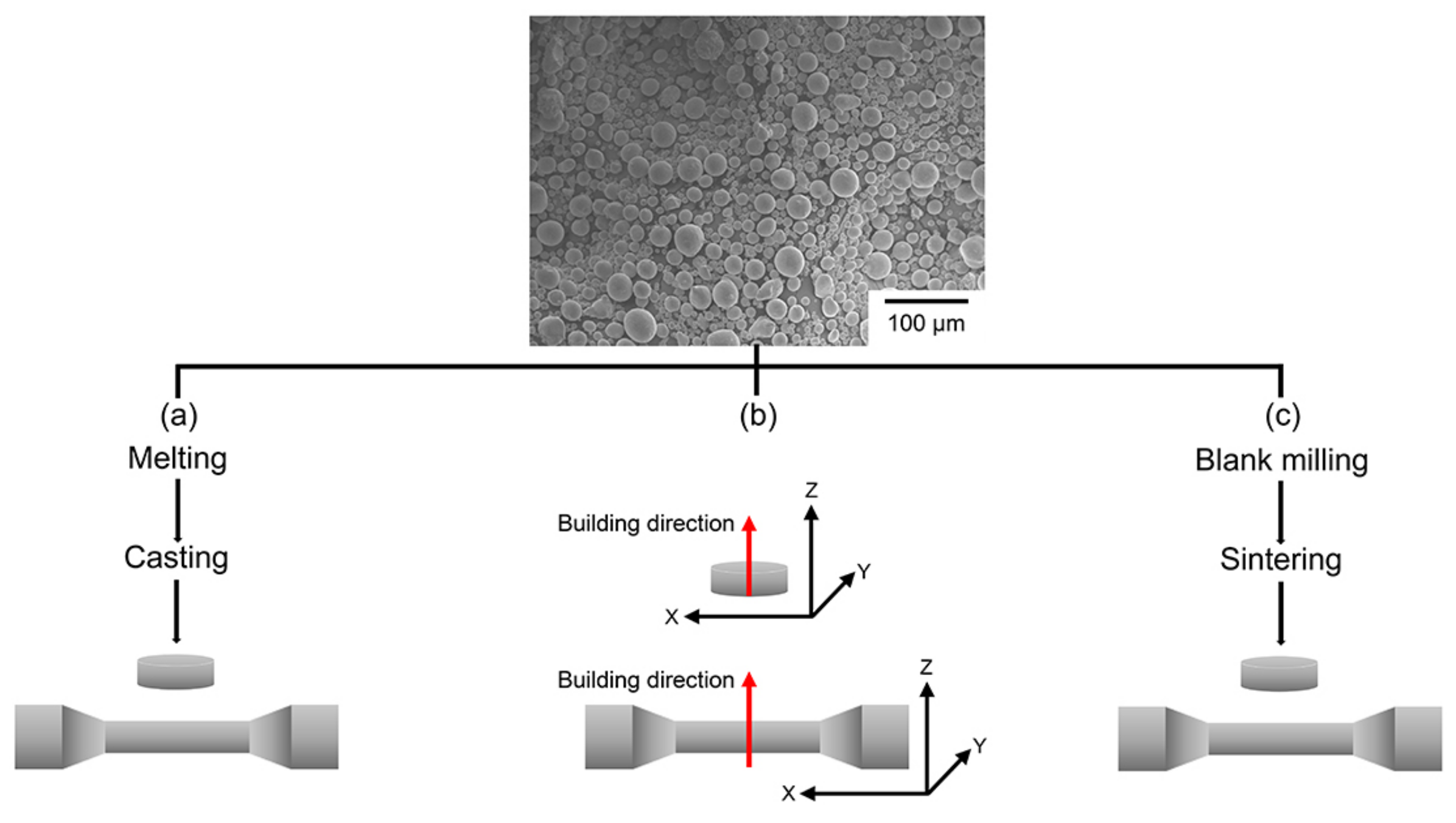
2.1. Specimen Preparation

Disc- (10 mm diameter and 3 mm height) and dumbbell-shaped (according to the ISO 22674 standard [16]) specimens were produced from a single spherical Ni–Cr–Mo alloy (Metalplayer Co., Ltd., Korea; Ni 68 wt%, Cr 22 wt%, and Mo 9 wt%) with an average particle size of less than 40 μm, using three different techniques (LWC, SLM, and SMM) (Figure 1). The 3D models were designed using CAD software (AutoDesk Inventor, Autodesk, USA). For the LWC specimens, the wax patterns were invested, evaporated in a furnace (Mihm-Vogt, Germany), and cast in a vacuum casting device (Neutrodyn Easyti, Manfredi, Italy) [4]. The horizontal SLM specimens were produced using an SLM machine (MetalSys150, Winforsys Co., Ltd., Korea) with an ytterbium fiber laser beam (spot size 0.08 mm and maximum power 200 W) in an atmosphere of nitrogen gas (flow rate of 5 L/min) [17,18]. The laser power was 175 W, the layer thickness was 35 μm, the hatch spacing was 60 μm, and the scan speed was 1800 mm/s. For the SMM specimens, the Ni–Cr–Mo powders were pressed into a disc-shaped mold using a uniaxial press at 200 MPa. The pre-sintered block was then soft-milled by a machine (Zenotec T1, Wieland Dental + Technik GmbH & Co. KG, Germany) and the specimens sintered at 1350 °C for 1 h under a purge of argon gas (flow rate of 0.6 L/mm) using a furnace (SinTagon, Denstar, Korea) [13].

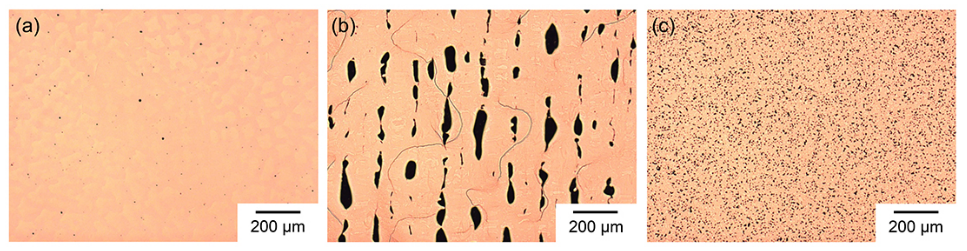
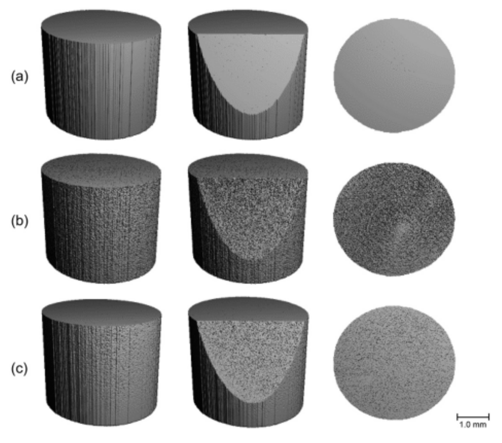
2.2. Micro-Computed Tomography (µCT)

The disc specimens were scanned using a µCT system (μCT 45, Scanco Medical AG, Switzerland) with 1500 projections/180°. The accelerating voltage was 90 kV, and the current was 88 μA. A 0.1 mm Cu filter was used. The integration time was 2000 ms, and the voxel size was 7.4 μm. The cross-sectional images were contoured, binarized, and finally reconstructed into 3D images using Scanco’s software (version 6.1). Three images for each alloy were saved as TIFF-type files.

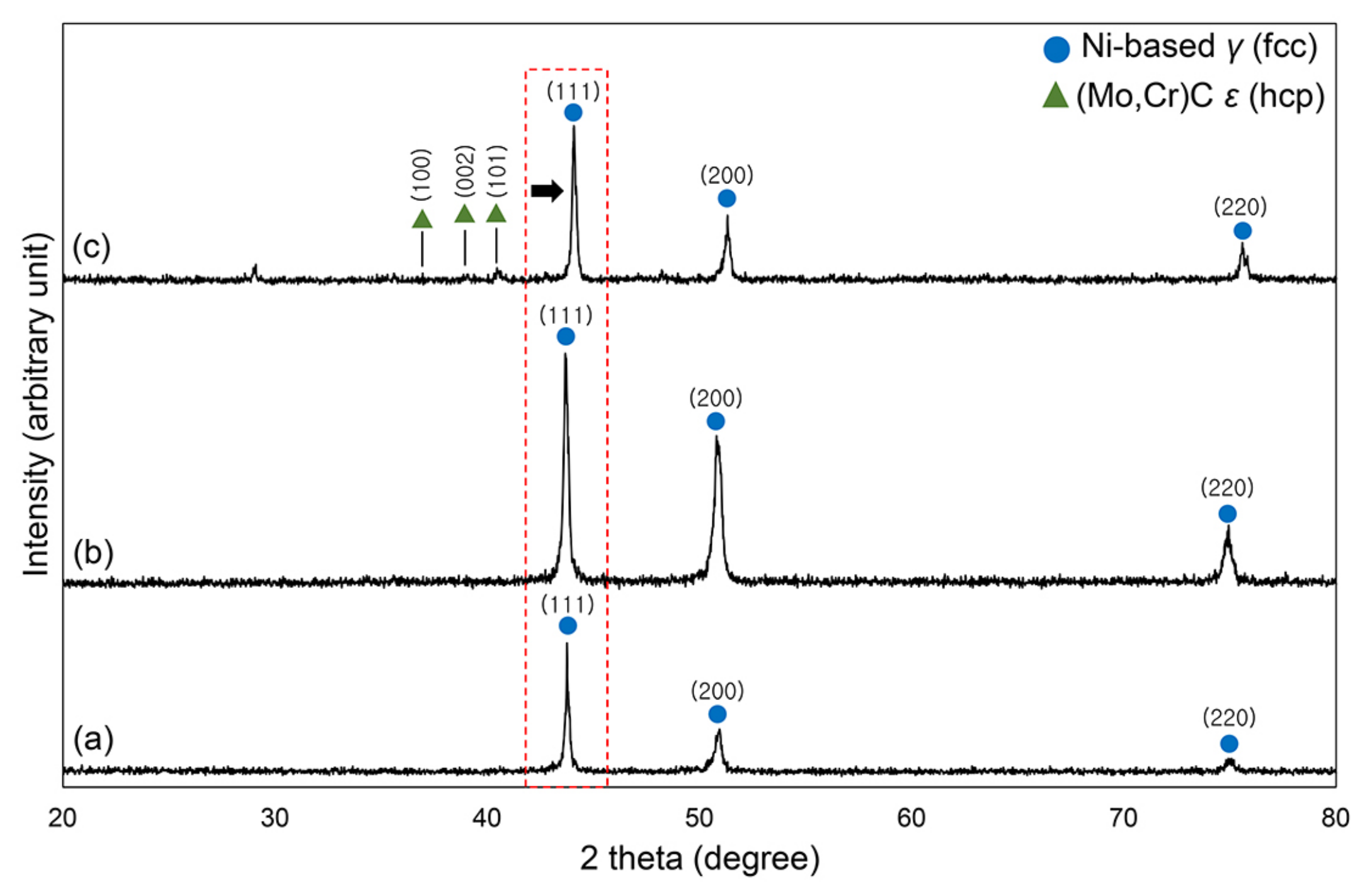
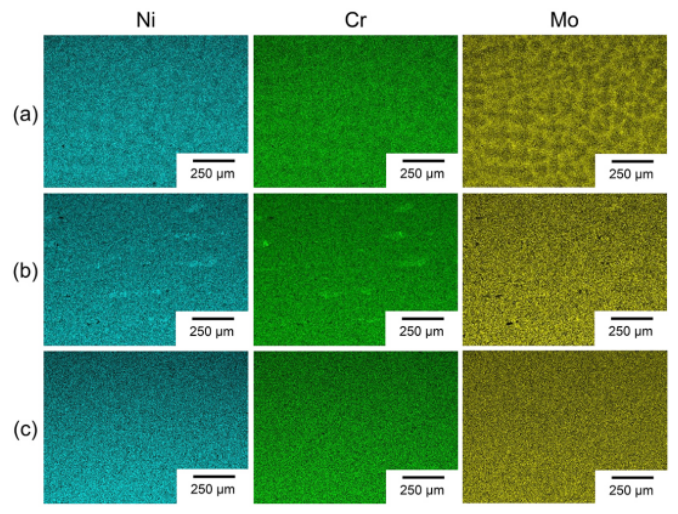
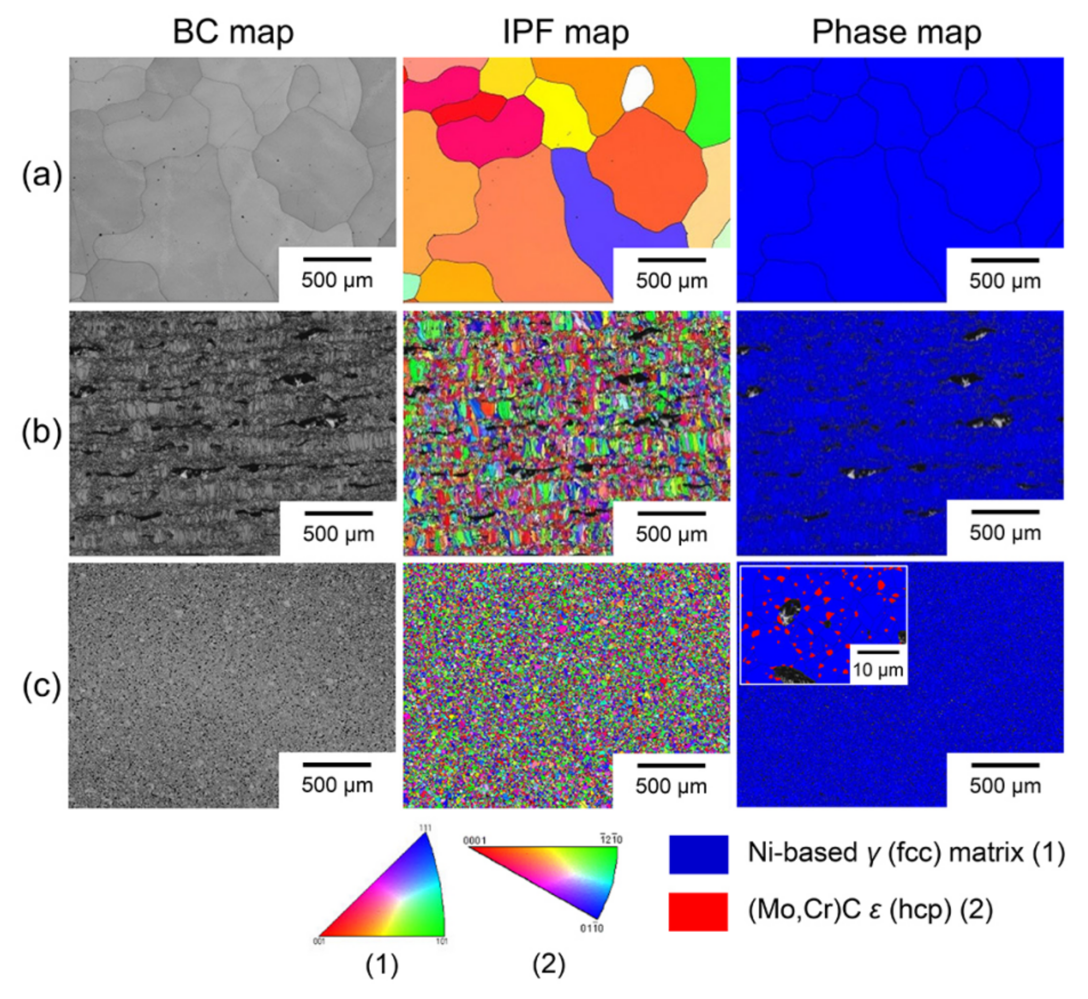
2.3. Microstructures

For the microstructural observations, the disc-shaped specimens were subjected to a polishing process using silicon carbide papers and a 0.05 μm colloidal silica suspension. This was followed by ultrasonic cleaning to remove any residual polishing particles remaining on the specimen surfaces. Thereafter, the microstructures were observed by optical microscopy (OM, MM-40/2U, Nikon Corp., Japan). The densities of the alloys were also measured using the Archimedes method. The phases of the alloys were observed by X-ray diffractometry (XRD) (MAXima_X XRD-7000, Shimadzu Corp., Japan) using Cu Kα radiation (λ = 0.1541 nm) at a 2𝜃 angle scan range of 20–80 degrees and voltage of 30 kV. The composition of the Ni–Cr–Mo alloys was analyzed by scanning electron microscopy (SEM, Merlin, Carl Zeiss AG, Germany) equipped with energy-dispersive X-ray spectroscopy (EDS, Oxford Instruments, UK) at 20 kV. SEM equipped with a detector (Nordlys Nano, Oxford Instruments) was also used to obtain electron backscattered diffraction (EBSD) scans and ascertain the crystallographic orientation. The band contrast (BC), inverse pole figure (IPF), and phase maps were all obtained for each alloy. Additionally, SEM images were taken of the single Ni–Cr–Mo alloy.

2.4. Mechanical Properties

A universal testing machine (3366, Instron Inc., USA) was used to subject the dumbbell-shaped Ni–Cr–Mo specimens to tensile force at a crosshead speed of 1.5 mm/min, according to ISO 22674 (n = 6 for each manufacturing technique) [16]. The tensile test allowed the calculation of four mechanical properties (tensile strength, yield strength at a 0.2% offset, percentage elongation, and Young’s modulus). As the data were normally distributed (Shapiro–Wilk test) and exhibited equal variances (Levene test), they were statistically analyzed using a one-way analysis of variance and Tukey’s post hoc test (α = 0.05).

3. Results and Discussion

Figure 2 presents the µCT images of the Ni–Cr–Mo alloys produced by the three different approaches. The LWC alloy, produced by the vacuum casting technique [4], showed a relatively pore-free image. Meanwhile, a high number of large and small pores were evenly distributed inside the SLM and SMM alloys, respectively.
The OM images of the Ni–Cr–Mo alloys are shown in Figure 3, where the results are comparable to the µCT results (Figure 2). The LWC alloy exhibited only a small number of pores, while the SLM alloy showed a lack-of-fusion porosity caused by insufficient penetration of the melt pool into the previous layer [19,20]. To minimize this lack-of-fusion porosity, the SLM process conditions, including the beam speed, layer thickness, and hatch spacing, should be further optimized [19]. The SMM alloy showed the formation of a high number of small and round-shaped pores, due to plastic deformation from the powder metallurgy process [21]. The density analysis also showed a higher density for the LWC alloy (8.42 g/cm3) when compared to the SLM (6.87 g/cm3) and SMM (7.62 g/cm3) alloys.
Figure 4 presents the XRD spectra for the Ni–Cr–Mo alloys. The XRD pattern revealed that all of the alloys were composed of a γ (face-centered cubic, FCC)-phased matrix, suggesting a solid solution of Ni [22]. The higher peaks exhibited by the SLM alloy may be explained by the higher crystallinity of the SLM specimens when compared to the LWC specimens. A slight shift of the (111) plane was observed in the SMM alloy, indicating a decreased cell size due to the low Mo concentration in the alloy [23]. Only the SMM alloy showed the formation of (Mo,Cr)C carbide with an ε (hexagonal close-packed, HCP) phase. It is already known that carbide precipitation increases the strength parameters of an alloy [24].
The EDS maps for the Ni–Cr–Mo alloys are presented in Figure 5. The maps for the LWC alloy showed segregation of the Cr and Mo elements along the grain boundaries during solidification [25]. The Ni, Cr, and Mo elements were also more homogeneously distributed in the SLM and SMM alloys than in the LWC alloy.
Figure 6 shows the EBSD images of the Ni–Cr–Mo alloys produced by the three different methods. The BC and IPF maps showed finer grains for the SLM and SMM alloys when compared to the LWC alloy, due to the different heating and cooling conditions of the SLM and SMM alloys. In particular, the IPF map for the SLM alloy showed ultrafine grains, which were caused by the high-temperature gradients involved in the SLM process [22]. Moreover, the phase map for the SMM alloy revealed the precipitation of carbide, confirming the XRD results (Figure 4).
Table 1 summarizes the mechanical property results for the Ni–Cr–Mo alloys. The porosity has a crucial impact on the final material properties and performance [18]. Therefore, since the SLM specimens were prepared in a horizontal direction, the tension load was applied perpendicular to the building direction (Figure 1) [18]. The LWC alloy showed a statistically higher yield strength value than the other two alloys (p < 0.001), which were statistically similar in value (p = 0.509), mainly due to its relatively pore-free microstructure (Figure 2a and Figure 3a). In addition, the Mo precipitate, which is seen in the EDS maps for the LWC alloy (Figure 5a), provides a high dislocation density [25], which may have enhanced the yield and tensile strength values for the LWC alloy [26]. While the SLM and SMM alloys showed homogeneous and fine grains (Figure 6), it would seem that the formation of a high number of pores (Figure 2 and Figure 3) decreased the properties of the alloys [27]. The percentage elongations in the SMM specimens were significantly greater than those in both the SLM and LWC specimens (p < 0.001), due to the greater precipitation of intragrain carbide and porous structures within the grains. All three alloys satisfied the ISO 22674 criteria for type 5 materials used in appliances, where the parts require a combination of high stiffness and proof stress (0.2% offset yield strength: >500 MPa; percentage elongation: >2%; and elastic modulus: >150 GPa) [16].
The main limitation of this study was that, to compare the different fabrication methods, a single Ni–Cr–Mo alloy, normally used to produce SLM alloys, was also used for the production of the LWC and SMM alloys (Figure 1). Nonetheless, the LWC and SMM alloys both showed favorable microstructures and mechanical properties. Despite the existence of numerous pores within the microstructure of the SLM alloy (Figure 3b), it still met the criteria for type 5 materials. Its ultrafine grain structure, due to its rapid solidification at a very high cooling rate [28], is known to produce desirable mechanical properties (in particular, yield strength and ductility) based on the Hall–Petch relationship [29], which explains that the mechanical properties of polycrystalline metals generally increase with a decrease in the average grain size. Furthermore, controlling the processing conditions of the SLM and SMM processes can significantly affect the mechanical properties of the resultant alloys [30]. In particular, the mechanical properties of SLM alloys can be notably altered according to the building direction [31]. In the current study, the dumbbell-shaped SLM specimens were prepared only in a horizontal direction (Figure 1) before testing (i.e., tension load perpendicular to the building direction). The SLM and SMM alloys (in particular, SLM) showed more porosity than the LWC alloy (Figure 2 and Figure 3). Notably, such pore formation can increase corrosion susceptibility, such as crevice and pitting corrosion [22]. However, the corrosion resistance and biocompatibility of the three resultant alloys were not investigated in the present study. Thus, caution is needed when generalizing the results of this study.
When compared to conventional casting, digital technologies such as SLM and SMM offer several advantages, including the cost-effective production of dental restorations, reducing the need for technical expertise, and minimizing environmentally harmful waste in the dental laboratory [32]. Notwithstanding, the SLM process still depends upon the technique used, and the required technical equipment remains very expensive [14]. The findings of this study also indicate the need to standardize and optimize the process parameters for SLM Ni–Cr–Mo alloys in order to reduce the formation of pores and thereby enhance the microstructure and mechanical properties of the resultant alloys [32]. Furthermore, when fabricating Ni–Cr–Mo frameworks, SMM would seem to be a viable and inexpensive alternative to conventional cast frameworks [14]. Although the current findings imply that SLM and SMM Ni–Cr–Mo alloys both have potential as new dental base-metal alloys, comprehensive in vitro and in vivo studies are still needed to verify their clinical performance and potential health risks [13]. In addition, commercial Ni–Cr–Mo alloy systems (materials and equipment) produced by digital manufacturing (AM and SM) need to be further developed for clinical use.

4. Conclusions

A single Ni–Cr–Mo alloy, with an identical elemental composition, was subjected to one conventional (LWC) and two new CAD/CAM-based digital manufacturing (SLM and SMM) techniques for the purpose of comparing the microstructures and mechanical properties of the three resultant alloys. The LWC alloy exhibited a small number of pores, while the SLM and SMM alloys showed a lack-of-fusion porosity, as well as small and round-shaped pores, respectively. Notwithstanding, the SLM and SMM alloys displayed more homogeneously distributed elements and finer grains (in particular, ultrafine grains in the SLM alloy) when compared to the LWC alloy. Furthermore, all three alloys satisfied the ISO 22674 mechanical properties criteria for type 5 materials.

Author Contributions

Conceptualization, K.-R.Y., T.H., T.-Y.K. and M.-H.H.; methodology, T.H., B.-K.M. and M.-H.H.; formal analysis, K.-R.Y., T.H., B.-K.M. and M.-H.H.; investigation, K.-R.Y. and T.-Y.K.; resources, T.-Y.K.; writing—original draft preparation, K.-R.Y. and T.-Y.K.; writing—review and editing, T.H. and M.-H.H.; visualization, K.-R.Y. and B.-K.M.; funding acquisition, T.-Y.K. All authors have read and agreed to the published version of the manuscript.

Funding

This research was supported by the National Research Foundation of Korea (NRF) grant funded by the Korea government (MSIT), grant number 2017R1A5A2015391. The APC was also funded by the National Research Foundation of Korea.

Institutional Review Board Statement

Not applicable.

Informed Consent Statement

Not applicable.

Data Availability Statement

Not applicable.

Acknowledgments

The authors also appreciate the Core Research Support Center for Natural Products and Medical Materials (CRCNM) for microscopy support.

Conflicts of Interest

The authors declare no conflict of interest. The funders had no role in the design of the study; in the collection, analyses, or interpretation of data; in the writing of the manuscript, or in the decision to publish the results.

References

  1. Xin, X.Z.; Chen, J.; Xiang, N.; Gong, Y.; Wei, B. Surface characteristics and corrosion properties of selective laser melted Co-Cr dental alloy after porcelain firing. Dent. Mater. 2014, 30, 263–270. [Google Scholar] [CrossRef] [PubMed]
  2. Kim, E.H.; Lee, D.H.; Kwon, S.M.; Kwon, T.Y. A microcomputed tomography evaluation of the marginal fit of cobalt-chromium alloy copings fabricated by new manufacturing techniques and alloy systems. J. Prosthet. Dent. 2017, 117, 393–399. [Google Scholar] [CrossRef]
  3. Wataha, J.C.; Messer, R.L. Casting alloys. Dent. Clin. N. Am. 2004, 48, 499–512. [Google Scholar] [CrossRef] [PubMed]
  4. Hong, M.H.; Hanawa, T.; Song, S.H.; Min, B.K.; Kwon, T.Y. Enhanced biocompatibility of a Ni–Cr alloy prepared by selective laser melting: A preliminary in vitro study. J. Mater. Res. Technol. 2019, 8, 1587–1592. [Google Scholar] [CrossRef]
  5. Roberts, H.W.; Berzins, D.W.; Moore, B.K.; Charlton, D.G. Metal-ceramic alloys in dentistry: A review. J. Prosthodont. 2009, 18, 188–194. [Google Scholar] [CrossRef]
  6. Kim, D.Y.; Kim, J.H.; Kim, H.Y.; Kim, W.C. Comparison and evaluation of marginal and internal gaps in cobalt-chromium alloy copings fabricated using subtractive and additive manufacturing. J. Prosthodont. Res. 2018, 62, 56–64. [Google Scholar] [CrossRef]
  7. Antanasova, M.; Kocjan, A.; Kovac, J.; Zuzek, B.; Jevnikar, P. Influence of thermo-mechanical cycling on porcelain bonding to cobalt-chromium and titanium dental alloys fabricated by casting, milling, and selective laser melting. J. Prosthodont. Res. 2018, 62, 184–194. [Google Scholar] [CrossRef]
  8. Li, J.; Chen, C.; Liao, J.; Liu, L.; Ye, X.; Lin, S.; Ye, J. Bond strengths of porcelain to cobalt-chromium alloys made by casting, milling, and selective laser melting. J. Prosthet. Dent. 2017, 118, 69–75. [Google Scholar] [CrossRef]
  9. ISO/ASTM 52900:2015. Additive Manufacturing-General Principles-Terminology; International Organization for Standardization/American Society for Testing and Materials (ISO/ASTM): Geneva, Switzerland; West Conshohocken, PA, USA, 2015. [Google Scholar]
  10. Pasang, T.; Tavlovich, B.; Yannay, O.; Jackson, B.; Fry, M.; Tao, Y.; Turangi, C.; Wang, J.C.; Jiang, C.P.; Sato, Y.; et al. Directionally-dependent mechanical properties of Ti6Al4V manufactured by electron beam melting (EBM) and selective laser melting (SLM). Materials 2021, 14, 3603. [Google Scholar] [CrossRef]
  11. Van Noort, R. The future of dental devices is digital. Dent. Mater. 2012, 28, 3–12. [Google Scholar] [CrossRef]
  12. Gokuldoss, P.K.; Kolla, S.; Eckert, J. Additive manufacturing processes: Selective laser melting, electron beam melting and binder jetting—Selection guidelines. Materials 2017, 10, 672. [Google Scholar] [CrossRef] [Green Version]
  13. Kim, H.R.; Kim, Y.K.; Son, J.S.; Min, B.K.; Kim, K.H.; Kwon, T.Y. Comparison of in vitro biocompatibility of a Co–Cr dental alloy produced by new milling/post-sintering or traditional casting technique. Mater. Lett. 2016, 178, 300–303. [Google Scholar] [CrossRef]
  14. Krug, K.P.; Knauber, A.W.; Nothdurft, F.P. Fracture behavior of metal-ceramic fixed dental prostheses with frameworks from cast or a newly developed sintered cobalt-chromium alloy. Clin. Oral Investig. 2015, 19, 401–411. [Google Scholar] [CrossRef]
  15. Kim, H.R.; Jang, S.H.; Kim, Y.K.; Son, J.S.; Min, B.K.; Kim, K.H.; Kwon, T.Y. Microstructures and mechanical properties of Co-Cr dental alloys fabricated by three CAD/CAM-based processing techniques. Materials 2016, 9, 596. [Google Scholar] [CrossRef]
  16. ISO 22674:2016. Dentistry-Metallic Materials for Fixed and Removable Restorations and Appliances; International Organization for Standardization (ISO): Geneva, Switzerland, 2016. [Google Scholar]
  17. Hong, M.H.; Min, B.K.; Kwon, T.Y. The influence of process parameters on the surface roughness of a 3D-printed Co–Cr dental alloy produced via selective laser melting. Appl. Sci. 2016, 6, 401. [Google Scholar] [CrossRef] [Green Version]
  18. Krakhmalev, P.; Fredriksson, G.; Yadroitsava, I.; Kazantseva, N.; du Plessis, A.; Yadroitsev, I. Deformation behavior and microstructure of Ti6Al4V manufactured by SLM. Phys. Procedia 2016, 83, 778–788. [Google Scholar] [CrossRef] [Green Version]
  19. Tang, M.; Pistorius, P.C.; Beuth, J.L. Prediction of lack-of-fusion porosity for powder bed fusion. Addit. Manuf. 2017, 14, 39–48. [Google Scholar] [CrossRef]
  20. Sabzi, H.E.; Rivera-Diaz-del-Castillo, P.E.J. Defect prevention in selective laser melting components: Compositional and process effects. Materials 2019, 12, 3791. [Google Scholar] [CrossRef] [PubMed] [Green Version]
  21. Bidulská, J.; Bidulský, R.; Actis Grande, M.; Kvačkaj, T. Different formation routes of pore structure in aluminum powder metallurgy alloy. Materials 2019, 12, 3724. [Google Scholar] [CrossRef] [Green Version]
  22. Yun, C.S.; Hanawa, T.; Hong, M.H.; Min, B.K.; Kwon, T.Y. Biocompatibility of Ni–Cr alloys, with the same composition, prepared by two new digital manufacturing techniques. Mater. Lett. 2021, 305, 130761. [Google Scholar] [CrossRef]
  23. Powers, J.M.; Wataha, J.C. Dental Materials: Properties and Manipulation, 10th ed.; Elsevier Mosby: St. Louis, MO, USA, 2013; pp. 133–149. [Google Scholar]
  24. Augustyn-Pieniążek, J.; Lukaszczyk, A.; Zapala, R. Microstructure and corrosion resistance characteristics of Cr-Co-Mo alloys designed for prosthetic materials. Arch. Metall. Mater. 2013, 58, 1281–1285. [Google Scholar] [CrossRef] [Green Version]
  25. Uranga, P.; Shang, C.J.; Senuma, T.; Yang, J.R.; Guo, A.M.; Mohrbacher, H. Molybdenum alloying in high-performance flat-rolled steel grades. Adv. Manuf. 2020, 8, 15–34. [Google Scholar] [CrossRef] [Green Version]
  26. Yang, H.L.; Abe, H.; Kano, S.; Matsukawa, Y.; Satoh, Y. Effects of molybdenum on microstructural evolution and mechanical properties in Zr–Nb alloys as nuclear fuel cladding materials. J. Nucl. Sci. Technol. 2015, 52, 1265–1273. [Google Scholar] [CrossRef]
  27. Schwarz, B.; Göhring, H.; Meka, S.R.; Schacherl, R.E.; Mittemeijer, E.J. Pore formation upon nitriding iron and iron-based alloys: The role of alloying elements and grain boundaries. Metall. Mater. Trans. A 2014, 45, 6173–6186. [Google Scholar] [CrossRef] [Green Version]
  28. Roach, M. Base metal alloys used for dental restorations and implants. Dent. Clin. N. Am. 2007, 51, 603–627. [Google Scholar] [CrossRef]
  29. Obayi, C.S.; Tolouei, R.; Mostavan, A.; Paternoster, C.; Turgeon, S.; Okorie, B.A.; Obikwelu, D.O.; Mantovani, D. Effect of grain sizes on mechanical properties and biodegradation behavior of pure iron for cardiovascular stent application. Biomatter 2016, 6, e959874. [Google Scholar] [CrossRef] [PubMed] [Green Version]
  30. Patel, B.; Favaro, G.; Inam, F.; Reece, M.J.; Angadji, A.; Bonfield, W.; Huang, J.; Edirisinghe, M. Cobalt-based orthopaedic alloys: Relationship between forming route, microstructure and tribological performance. Mater. Sci. Eng. C 2012, 32, 1222–1229. [Google Scholar] [CrossRef]
  31. Yu, J.M.; Kang, S.Y.; Lee, J.S.; Jeong, H.S.; Lee, S.Y. Mechanical properties of dental alloys according to manufacturing process. Materials 2021, 14, 3367. [Google Scholar] [CrossRef]
  32. Çömlekoğlu, M.D.; Çömlekoğlu, E.M. Digital dental era. Mater. Sci. Eng. J. 2017, 1, 1004. [Google Scholar]
Figure 1. Schematic diagram of three manufacturing processes (lower) using single spherical Ni–Cr–Mo alloy (upper, SEM image, magnification = 250×) for specimen preparation: LWC (a), SLM (b), and SMM (c).
Applsci 11 09308 g001
Figure 2. µCT images of Ni–Cr–Mo alloys: LWC (a), SLM (b), and SMM (c). Cylindrical-shaped 3D images (left), cylindrical-shaped images with cut planes (middle), and top images of cylinders (right).
Applsci 11 09308 g002
Figure 3. Optical microscopy images (magnification = 50×) of Ni–Cr–Mo alloys: LWC (a), SLM (b), and SMM (c). Red arrow in (b) indicates SLM building direction.
Applsci 11 09308 g003
Figure 4. XRD spectra of Ni–Cr–Mo alloys: LWC (a), SLM (b), and SMM (c). Peaks corresponding to γ matrix and ε carbide phases were identified by ICDD card no. 03-065-6291 and 00-001-1188, respectively. Black arrow in SMM alloy (c) indicates shift of (111) plane.
Applsci 11 09308 g004
Figure 5. EDS images of Ni–Cr–Mo alloys (magnification = 100×): LWC (a), SLM (b), and SMM (c).
Applsci 11 09308 g005
Figure 6. EBSD images of Ni–Cr–Mo alloys (magnification = 100×): LWC (a), SLM (b), and SMM (c). Rectangular image within phase map (c) shows higher magnification, clearly revealing two different phases (magnification = 3000×).
Applsci 11 09308 g006
Table 1. Mechanical properties of three Ni–Cr–Mo alloys produced using three different manufacturing techniques (n = 6).
GroupTensile Strength (MPa)0.2% Offset Yield Strength (MPa)Elongation (%)Elastic Modulus (GPa)
LWC862 ± 49 a1753 ± 44 a4.4 ± 0.9 a355 ± 37 a
SLM566 ± 25 b532 ± 23 b5.6 ± 1.3 a440 ± 35 b
SMM746 ± 34 c554 ± 31 b21.5 ± 1.8 b287 ± 16 c
1 Within the same parameter, the same lowercase superscripted letters (a, b, and c) indicate no significant differences among three alloys (p > 0.05).
Publisher’s Note: MDPI stays neutral with regard to jurisdictional claims in published maps and institutional affiliations.

