Article

Design Options to Improve the Dynamic Behavior and the Control of Small H-Darrieus VAWTs

DICAM—Department of Civil, Environmental and Mechanical Engineering, University of Trento, via Mesiano 77, 38123 Trento, Italy
Appl. Sci. 2021, 11(19), 9222; https://doi.org/10.3390/app11199222
Submission received: 2 September 2021 / Revised: 22 September 2021 / Accepted: 26 September 2021 / Published: 3 October 2021
(This article belongs to the Collection Wind Energy: Current Challenges and Future Perspectives)

Abstract

:
H-VAWTs or straight blades VAWTs are the most common turbine architecture employed for small VAWTs. The manufacture of straight, constant chord blades, coupled with the transport advantages, make this choice technologically simpler, compared to curved (eggbeater) type or curved-bent (Gorlov) type, allowing a large selection of materials, and design solutions. Recently, the strategies to accomplish the task of zero-emission buildings identified wind energy exploitation in the urban environment as one of the most promising. Micro and mini wind turbines installed on buildings (BAWT—building-augmented wind turbines) are considered the candidate technology after that of photovoltaic panels; under certain conditions, these technologies can be combined to obtain the maximum natural resources exploitation in the urban environment. VAWT, compared to HAWT, would ideally perform better in the fast-changing, turbulent winds, typical of the built environment. Additionally, its 3D shape favors a better architectonic integration with the volumes of the building. Nevertheless, despite these claimed advantages, this architecture did still not come to the expected fruition and experience, which revealed that the stochastic nature of the wind resource in the built environment determines a quite challenging context, reflecting not only the structural endurance, but also the operations and the annual energy production. These site characteristics stress the detrimental effect of the high polar inertia of this architecture hampering, be it a reduction in the acceleration and deceleration capability of the rotor, the required adaptation of the rotational speed to the varying wind conditions, or compromising any form of robust control. This leads to poor aerodynamic performance and potential structural damages. This paper contributes to mitigating the issue of the high rotor polar inertia of the H-VAWT without affecting other essential design requirements (strength, performances, needs of smooth control). The work identifies the design parameters governing the rotor acceleration and deceleration and develops a rational design procedure aimed at improving the H-VAWT control and performance.

1. Introduction

According to the rational classification of the rotor architectures introduced by G. Darrieus in 1930 [1], VAWTs’ concept of base torque generation on the aerodynamic lift principle was subjected to intense theoretical and experimental development during the 1970s and 1980s [2,3,4]. The concept was initially intended for inland installation of small to medium size units, up to 500 kW [5]. While in the U.S.A., the preferred rotor adopted the troposkein blade shape (also popularly named eggbeater rotors), many prototypes, especially in the U.K. and Europe, moved to H-type [6]. According to this design, the straight blades offered the possibility to adopt various control mechanisms, such as pitch control or blade reefing systems. After a period of latency, only recently VAWTs gained a renewed interest toward two completely different turbine scales and application fields: the very small sizes (up to about 10 kW), driven at the beginning of the 2000s from the potential applications in urban environments [7,8,9], and the giant offshore turbines concepts of the 2010s (up to 30 MW) by several feasibility studies [10,11,12,13,14,15], and UE granted projects [16]. In the urban field, fluid-dynamic limitation due to the wake interaction between the turbine and the building [7] restricts the size to the order of about 10 kW, limiting rotors to a maximum diameter of about 5–6 m [8]. Concerning distributed wind applications in suburban or rural areas, the adoption of rotors on the top of towers to intercept higher winds poses, again, a limitation on the maximum size of the H-Darrieus turbine caused by the complex structural issues of the rotor-arms-tower connection, and thus, the consequent development remained in the area of very small size turbines. An H-VAWT 200 kW wooden tower prototype has been running discontinuously since 2010 at the University of Uppsala [17], hampered by rotor-tower resonance. This area of application inherited a lack of suitable theoretical and numerical design tools for the design, and a considerable number of projects have a very long commercial latency period, proving the complex design path, and many problems of unreliability and underperformance have been reported for commercial models. All this is to say that H-VAWTs, despite some attractive features, still suffer from some shortcomings, which partly can be handled with a better knowledge of fluid dynamics and structural dynamics. Small straight blades VAWTs are characterized by intrinsically high polar inertia, due to the peripheral arrangements of the blades concerning the rotating shaft. This feature determines a beneficial flywheel effect on the drive train, smoothing down torque oscillations induced by the complex aerodynamics of the rotor. On the other side, high inertia rotors suffer from huge response times, and the acceleration/deceleration rate is far from the required one under the presence of wind unsteadiness, wind gusts, and wind drops. This behavior results in a large idling time, which is felt to be one of the leading causes of the poor performance claimed for these wind energy conversion systems in gusty environments, as urban sites are. It was proved [18] that the power reduction caused by the inertia of wind turbines changed proportionally with their natural time constants. Additionally, the frequency of the wind speed variation and the average of the absolute value of the rate of wind speed change demonstrated to play an important role about the output power: in fact, when the wind speed varies rapidly, the above two factors of the wind speed increase as well, determining a greater reduction in wind turbines power output.
Many works have been devoted to understanding the factors that influence such behavior and the mitigation effects, although the papers analyzed the partial design characteristics, such as blade chord, number of blades, rotor solidity, and rotor aspect ratio, as well as the parametric effect of these single variables on turbine inertia [19,20,21,22,23,24,25,26].
More comprehensive work was undertaken by Hara et al. [27], who investigated the response of a straight-bladed VAWT to pulsating winds. The phase delay between the rotational speed and the wind variation was experimentally and numerically analyzed. The results show a constant value by changing the moment of inertia, the wind cycle, and the wind amplitude. The phase delay resulted to be approximately π / 2 when the wind amplitude was large. The experimental evidence of the rate of change in the rotational speed suggested a relation between the rotational speed width and the pulsating wind amplitude. The efficiency of the H-VAWT in a pulsating wind with unvarying amplitude stayed almost constant under both changes in the moment of inertia and the wind cycle, but a decrease was recorded when the wind amplitude was large.
Nguyen and Metzger [28] combining measured wind data and blade element momentum (BEM) simulations, investigating an H-VAWT response capability in turbulent winds. Even though the energy production adopting an ideal tip speed ratio controller resulted in being much higher than that obtained with a fixed angular speed, a marked efficiency drop was registered when the rotor was no longer capable of closely tracking the gusts. The same authors [29] also investigated different VAWT architectures (acting on height-to-diameter aspect ratio, blade airfoil shape, rotor solidity, and moment of inertia) to determine the best configuration to maximize the energy harvest from urban gusty winds, showing that the optimal power coefficient versus tip speed ratio curve is not necessarily the one exhibiting the highest peak, but rather the broadest shape. Such works indicate that not all of the parameters are of identical importance for a successful final product. Some of them (such as the choice of airfoils, supporting strut configuration, shape, solidity, and the material) are more sensitive and critical than others.
As is evident from the preceding review, most of the works pointed to the effect of a single or a few design parameters, without linking them in a unique and rational design path.
The long in-field experience collected by the author over about 15 years of tests in open areas and wind tunnels [30] recognized the high polar inertia of the rotor as the most detrimental characteristic of small VAWTs, leading to a severe drop in output energy expectation and structural failure. This issue can only partially be alleviated by the control strategy. Based on these studies, this paper proposes a design procedure aimed to improve the control of small H-VAWTs without affecting essential design requirements (strength, performances, needs of smooth control). The procedure can be easily extended to other VAWT architectures. This approach considers all principal parameters involved in the turbine design. Section 2 provides the background to analyze the factors influencing the dynamic behavior of the H-VAWT. Due to the relevance of polar inertia in the present discussion, Section 2 introduces an analytical model to evaluate and compare the inertial properties of H-VAWT and HAWT rotors. The effect of polar inertia on rotor dynamics is then explained as a response to unsteadiness. The relative gust tracking capability, through the introduction of the wind tracking index, is commented on. Section 3 discusses how to maximize the dynamic characteristics of the turbine by separating the effect of single groups of variables, according to a well-known general approach introduced by Ashby [31], here applied to wind turbine design. Section 4 discusses the results of the procedure, and Section 5 concludes the work with some design indications and recommendations.

2. Background

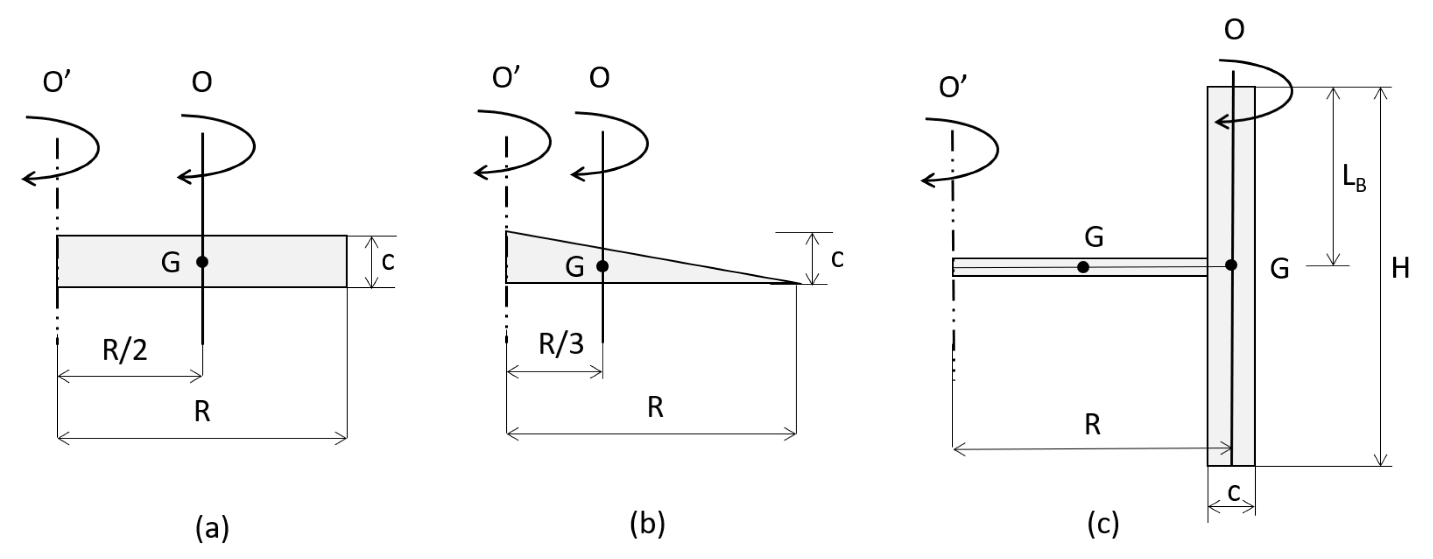
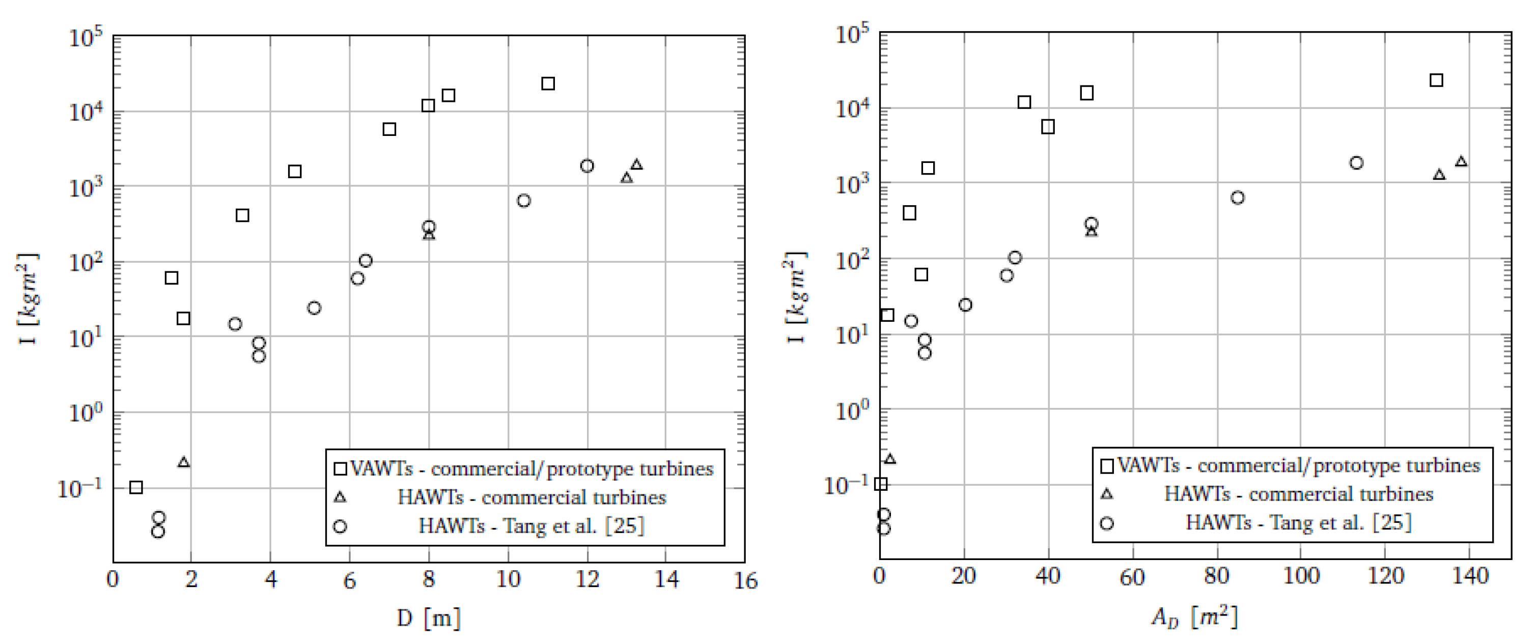
2.1. Inertial Properties of the Rotors

Generally speaking, the momentum of inertia of wind turbines rotors is much larger than that of the other components of the power train, so the contribution of the latter can be neglected for a first step dynamic analysis approach. The moment of inertia of the rotor consists essentially of the sum of that of the blades and that due to the hub (or to the spokes, in the case of a VAWT). A schematic and general representation of the geometric configuration of the blades of horizontal and vertical axis turbines, useful for an approximate but sufficiently accurate calculation of the moment of inertia, is given in Figure 1. Note that, in general, L B = k b · H , where 0 k b 1 , depending on the arm to the blade connection point.
The moment of inertia with respect to the O’ axis is given by the following:
I = I + m d 2
where I is the moment of inertia concerning the generic axis O’, I is the moment of inertia concerning the O axis (parallel to O’) that crosses the blade center of gravity, and m is the mass of the body. Typically, the blade of a HAWT has a morphology falling in between a tip tapered and constant chord that can be assimilated to a rectangle and a triangle, respectively (Figure 1a,b).
The moment of inertia of a rectangular shaped blade I R of mass m R is is equal to the following:
I R = I R + m R R 2 2 = 1 12 m R R 2 + m R R 2 2 = 1 3 m R R 2
On the other hand, the moment of inertia of a triangular shaped blade I T with mass m T is equal to the following:
I T = I T + m T R 3 2 = 1 18 m T R 2 + m T R 3 2 = 1 6 m T R 2
Assuming that the density of the blade material is the same, the moment of inertia of a constant-chord blade is double that of a variable-tapered, triangle-shaped one. Commercial blades with a length less than 10 m, where the width of the spar-cap box and the skin do not vary along the blade, show the following main relationships for the inertia, mass, and blade length [32]:
I = k I m B R 2
where k I ranges from 0.21 to 0.22 [33] ( 1 / 5 to 2 / 9 ), figures that well agree with the outcome of the above analytical model.
Focusing on H-Darrieus VAWTs, the moment of inertia is equal to the sum of that of the blades support arms I S (spokes) and one of the blades I B in the following formula (see Figure 1c):
I H = I S + I B
Assuming both blades and support arms have a constant chord c, they can be assimilated to rectangular bodies, and the moment of inertia results in the following:
I H = 1 3 m S R 2 + 1 12 m B c 2 + m B R 2
Introducing the definition of rotor solidity σ [34],
σ = N B c H 2 R H = N B c 2 R
and substituting the value of c from the previous relation (assuming m S = m B ), the following holds:
I H = 4 3 + 1 3 σ 2 N B 2 m B R 2
The term 1 3 σ 2 N B 2 is much smaller than 1, and thus, we have the following:
I H 4 3 m B R 2
It should be noted that the mass of a VAWT blade is, for structural reasons, equal to 5 ÷ 10 times that of a HAWT of the same radius. This means that, at least when smaller sizes are considered, the inertia of an H-VAWT (with the same number of blades and swept area, and considering rotors having different aspect ratios) is from ten (for relatively large swept areas) to hundred times (for small swept areas) higher than the HAWTs counterparts. Such a result is confirmed by the plotted data of some commercial VAWTs in Figure 2, and compared to HAWTs of a similar diameter (left) and rotor swept area (right).
It has to be pointed out that the former data are nevertheless hard to be retrieved from published literature, as can be seen from the scarcity of data listed in Table A1.

2.2. Response to Aerodynamic Unsteadiness

The capability of the turbine to react promptly to rapidly changing incoming wind conditions depends on both the time scale of the air velocity fluctuations and the response characteristics of the turbine itself. VAWTs generate a highly unsteady aerodynamic environment. The incident air velocity is not constant in both intensity and direction, resulting in varying chordwise and normal blade velocity components [34,35]. Besides this intrinsic unsteadiness induced from VAWT kinematics, even in steady-state flow, another source is given by the vortexes generated by the blade-to-tower and blade-to-blade interaction. An additional unsteadiness is provided by the wind shear, the natural turbulence, and the gusts. This complex flow field reflects the periodic and random variation of driving and normal blade forces and pitching moments. With concern for instance to the typical operational context of a small wind turbine within the urban environment, both flow distortions and turbulence are created by natural and anthropic elements, such as trees, buildings, etc. [7,35]. Even though just a few works have investigated the impact of turbulence on small wind energy conversion systems [36,37], it is recognized that the turbulence spectrum in the urban roughness sub-layer is characterized by a peak between 10 1 Hz and 1 Hz, thereby determining a characteristic time scale on the order of seconds [38]. Several characteristic times can be identified for a small wind turbine, governing the transient process between two steady-state operating conditions. They can be related to the relaxation of the boundary layer around the blades (leading to a time constant on the order of 10 2 to 10 3 s [39]), as well as the one of the rotor wake (where a time constant on the order of 0.1 to 1 s can be inferred, see again [39]). The inertial response of the turbine appears to be one (or even two) orders of magnitude higher than those related to the aerodynamic phenomena described above (being on the order of tens of seconds, or even a minute; see [18]), especially in the case of VAWTs.

2.3. Gusts Tracking

The theme of VAWTs rotor gust tracking capability was approached analytically in a previous work by the author [39], where the relationships between inertia and rotor radius, inferred from datasheets of commercial and prototype turbines, were investigated. As shown in Figure 2, H-VAWTs inertia is, at least for small sizes, more than one order of magnitude higher than that of HAWTs for the very same diameter or swept area: as a consequence, VAWTs response times are much greater than those of their horizontal-axis counterparts, especially at low wind speeds, prompting a severe limitation to the efficient adoption of vertical axis rotor architectures within urban sites, which are generally characterized by a low wind potential, as well as rapidly varying wind conditions. Being that the present study is a natural continuation of the above-discussed work, its main features and results are here summarized; the complete model is fully detailed in [39].
To test the capability of a turbine to effectively adapt its rotational speed to satisfy a prescribed control strategy, two parameters were introduced and compared: the required rotor acceleration (RRA, defined as the acceleration required by the rotor to track a given gust) and the available rotor acceleration (ARA, defined as the maximum angular acceleration achieved when the rotor is free to accelerate under that gust). The required rotor acceleration (RRA) derives from the differentiation of the equation expressing the optimum tip speed ratio.
λ o p t = Ω R V
Therefore, for a given rotor radius, we have the following:
R R A = Ω ˙ = λ o p t R V t = λ o p t R V ˙
where Ω ˙ is the rotor acceleration/deceleration, λ o p t is the design tip speed ratio that should be kept constant during normal operation to operate at maximum power coefficient, and V ˙ is the gust acceleration.
The available rotor acceleration (ARA) is defined on the basis of the rotor’s allowable angular acceleration given by the mechanical balance of the power train as follows:
N B I Ω ˙ Q a e r o Q g e n
Under the (conservative) hypothesis that the resistant torque Q g e n = 0 , the acceleration of the rotor is equal to the following:
A R A = Ω ˙ = Q a e r o N B I
where N B is the number of rotor blades, I is the single blade inertia according to Equation (1), and the aerodynamic torque is Q a e r o defined as follows [33]:
Q a e r o = ρ a A D V 3 C P , M A X ( λ ) 2 Ω .
Moving from the definition of the latter parameters, a further synthetic index, the wind tracking index ( W T I , defined as the ratio between the A R A and the R R A ) was introduced to assess the capability of the system to effectively track wind fluctuations:
W T I = A R A R R A .
The condition that the available rotor acceleration is higher than the required one, or A R A > R R A , implies that the condition W T I > 1 has to be satisfied. It can be easily drawn that the W T I , even if not capable of quantifying the exact amount of annual energy lost, due to the retarded response of the turbine, can be used to obtain an indication about the suitability of a given turbine architecture to adapt to given site characteristics. In the following, the maximization of this parameter is used to propose an H-VAWT design criterion.
Figure 3a shows the record of gust cumulative probability occurrence sampled at the experimental test field of the University of Trento [9,40,41]. The curve derives from the interpolation experimental data. About 90% of the gusts presents an acceleration rate less than 2.5 m/s 2 . From this evidence, three typical wind accelerations—0.6 m/s2 (Figure 3b), 0.9 m/s 2 (Figure 3c), and 1.2 m/s 2 (Figure 3d)—are selected to evaluate representative W T I s of a collection of commercial wind turbines having different rotor diameters, computed for different unperturbed wind speeds. It can be easily drawn that small H-type Darrieus VAWTs are dramatically penalized, compared to their horizontal-axis counterparts, at least for low wind speeds, not actually exceeding a maximum W T I of about 0.6 for average-high gustiness. The larger the wind gust, the lower the WTI, indicating an increased difficulty of the turbine to accelerate/decelerate.

2.4. Acceleration/Deceleration Capability

The above-described difference in inertial properties between HAWT and VAWT, combined with the different adopted tip speed ratios, allow to draw some consideration about the different acceleration/deceleration capacity of the VAWTs, compared to HAWTs.
The ratio between the angular accelerations of the two architectures, considering the relative rotor inertias (assuming the same number of blades), and the ranges of the design tip speed ratios ( λ H A W T = 6 ÷ 9 , λ H V A W T = 2 ÷ 3 ), is therefore equal to the following for slow running, small size turbines ( I H V A W T I H A W T = 300 ):
Ω ˙ H V A W T Ω ˙ H A W T = λ H A W T λ H V A W T I H A W T I H V A W T 1 100
and equal to the following for fast running, medium size turbines ( I H V A W T I H A W T = 30 ):
Ω ˙ H V A W T Ω ˙ H A W T = λ H A W T λ H V A W T I H A W T I H V A W T 1 10
clearly showing an intrinsic poor accelerating/decelerating capability of the H-type vertical-axis architecture, compared to the case of HAWTs.

3. Wind Tracking Index Maximization Procedure

Moving from the definition of the wind tracking index introduced in Section 2.3, a discussion can be promoted to draw some indications about the potential improvement of the design philosophy of VAWTs, aimed to operate in a gusty, typically low wind speed environment, such as, for instance, the urban one. This discussion deals with the issue of turbine acceleration/deceleration and disregards the analysis of the self-aligning capability of the machine. In fact, unlike their horizontal-axis counterparts, VAWTs do not need rotor orientation systems, as they are inherently panemone, which theoretically implies a better ability to gather energy in gusty environments with frequent changes in wind directions. The goal of the proposed analysis is to discuss a design procedure aimed to obtain better reaction capability in the operational range between cut-in and cut-out wind speeds, without entering in the discussion of self-starting behavior.
The model is based on the well-known approach introduced by Ashby [31], which guides the designer throughout an educated process to the general purpose of an optimized project. Such an approach identifies both the performance to be maximized (or minimized) and equations for the variables set as design constraints (i.e., maximum allowable deflection, and limit mechanical resistance). The performance and constraints form a set of equations that, through substitutions and analytical manipulations, lead to a single performance equation of the following form:
P = f 1 ( F 1 ) · f 2 ( F 2 ) · . . . . f n ( F n )
or
Δ P P = Δ f 1 f 1 + Δ f 2 f 2 . . . . . . + Δ f n f n
where f i are separate functions of groups of parameters F i , called performance metrics, describing functional requirements, geometric data, material properties and so on. When the groups are separable and independent, maximization (or minimization) of the performance can be obtained by maximizing (or minimizing) singularly any group F i appearing in the equation.
For the present case, the maximization of the W T I performance starts from a suitable expression of such a parameter:
W T I = Q a e r o R N B I λ o p t V ˙
= 1 2 N B ρ a c H C T V 2 R 2 N B I λ o p t V ˙
= 3 4 ρ a V 2 V ˙ C T λ o p t c H m B
Introducing the rotor solidity for an H-VAWT ( σ = N B c H 2 R H ), Equation (8) can be rewritten as follows:
W T I = 3 4 A D ρ a V 2 V ˙ C T λ o p t 1 m B σ N B
being A D = 2 R H . The solidity and the tip speed ratio are related to a general equation of the form σ = α λ o p t β , with α and β constants. Figure 4 shows a collection of σ λ o p t data for current and past commercial H-VAWTs, from which the constants α and β can be deduced as best fit of an exponential low.
Therefore, Equation (9) becomes the following:
W T I = 3 4 A D ρ a V 2 V ˙ α C T N B λ o p t β + 1 1 m B
To include the blade material properties in Equation (10), the blade mass equation can be written as follows:
m B = ρ B A B H
To maximize W T I , the mass cannot be as small as desired without compromising the blade structural integrity. It is seen clearly from Figure 1 that the H-VAWT blade is loaded mainly along the radial direction [42]. Therefore, a constraint has to be set on maximum blade bending induced stresses [43]: the maximum mechanical stress σ m occurs at that point y m of the surface of the blade section placed at the maximum distance from the neutral axis (see Figure 5). The following constraint can, therefore, be set as the following:
σ m = M b y m J = M b W < σ a d m σ f
where M b is the bending moment, J is the surface momentum of inertia of the blade section, W is the modulus of resistance σ a d m is the failure strength of the material, and σ f is the suitable safety factor. Failure occurs if the local stress exceeds σ a d m (which is chosen according to the main failure option of the turbine, i.e., ultimate, fatigue, or buckling).
According to Ashby [31], the blade section has a strength efficiency that depends on its shape, and can be measured by the parameter Φ f as follows:
Φ f = W W 0
where W 0 is the section modulus of a reference square section having the same sectional area A B :
W 0 = b 3 6 = A B 3 / 2 6
Thus the strength efficiency becomes the following:
Φ f = 6 W A B 3 / 2
This parameter is independent of the scale and other parameters and, according to Ashby, can range from 1 to about 10 depending on the shape of the resisting spar of the blade (see Figure 6). By incorporating the parameter Φ f , Equation (12) becomes the following:
6 F f 2 3 L B A B 3 / 2 Φ f < σ a d m σ f
The ratio 2 3 appearing in Equation (13) is the point of application of the equivalent pressure center on the blade considered a beam of length L B (see Figure 1), subjected to a bending force F f [44].
For the present analysis, a reasonable approximation can be made by using the expression of the aerodynamic load as a formal bending force:
F f = 1 2 ρ a c L B C N V 2
With specific concern to H-VAWTs, depending on both turbine size and tip speed ratio, the magnitude of the centrifugal forces can be higher than the aerodynamic actions. The centrifugal loads are caused by the rotation, and the bending loads are generated by the distance from the blade to the arm connecting point. Therefore, in the designing of H-VAWT, the bending strength is mainly considered [45]. This occurrence can be taken into consideration by setting the blade normal coefficient as being magnified by a further coefficient k C , higher than one, accounting for the additional forces caused by the centrifugal load, that is, for the zero pitch angle as follows:
C N = k C C N
The representation of the normal and tangential force coefficients is shown in Figure 7. By the introduction of the constraint given by the relationship of Equation (13), the maximum allowable blade mass is given by the following:
m B = K 1 1 H 1 / 3 F f Φ f 2 / 3 ρ B σ a d m 2 / 3 σ f 2 / 3
Finally, by substitution of the latter set of equation, the WTI becomes the following:
W T I = K 2 ρ a 1 / 3 V 2 / 3 V ˙ D H c 2 / 3 H 7 / 3 Φ f 2 / 3 1 N B 1 λ o p t β + 1 C T C N 2 / 3 σ a d m 2 / 3 ρ B 1 σ f 2 / 3
where K 1 and K 2 are numerical constants collecting all figures. It is convenient now to group the variables into homogeneous indexes. Rearranging the latter equation, with the help of the relationship between solidity and tip speed ratio, one obtains the following:
W T I = K 3 ρ a 1 / 3 V 2 / 3 V ˙ E Φ f 2 / 3 1 D 1 N B 1 A R 4 / 3 G C T C N 2 / 3 1 λ o p t ( 1 + β ) / 3 F σ a d m 2 / 3 ρ B 1 σ f 2 / 3 M
where K 3 is a numerical constant resembling all previous constants. WTI is thus split by convenience into 4 groups, named E (environment), G (geometry), F (functional) and M (material). σ f is grouped within index M because any given material and manufacturing technology determines a specified safety factor.
It should here be emphasized that the previous equation is one of the possible arrangements of the relationship between the variables. Other formulations can be inferred by proper manipulation of the auxiliary equations.

4. Discussion

The inspection of Equation (17) enables some observations. First of all, from the physical point of view, the equations appear consistent: the environment index E shows that higher air density and stronger wind speeds increase the accelerating capability of the turbine, such a result also being achieved if the average gustiness of the site is low. Of course, as the definition of WTI is pseudo-static, the effect of the turbulence intensity cannot be considered in this analysis.
As far as the geometric index G is concerned (Equation (17)), small diameters determine a dramatic reduction in the inertia, with a beneficial effect on the rotor acceleration capability. The same goal is obtained by reducing the blade number, which is responsible for a linear reduction in the rotor inertia (for instance, by a factor of 1 / 3 if, from the initial 3 blades design choice, one blade is suppressed). Additionally, the adoption of a structurally efficient blade section, implying a substantial reduction of the blade mass required to perform the goal, has the consequence of increasing, by an order of magnitude, the factor Φ f (see Figure 6).
The functional design parameter index F shows that an increase in the ratio of the tangent to normal coefficients produces higher torque, thus boosting the acceleration of the rotor. An analogous result is achieved through the reduction of the design tip speed ratio, which implies a higher design solidity and therefore, a higher aerodynamic torque. This outcome aligns with the conclusions of Milborrow [44], stating that, assuming a wind intensity and a given number of blades, the rotor torque is inversely proportional to the tip speed ratio, and thus, a lower tip speed ratio enables a better acceleration capability. Furthermore, lower tip speed ratios produce a decrease in the rotational speed and thus, alleviate the structural stress (which is principally due to centrifugal forces).
Finally, the material index M shows that, if the constraint of blade strength has to be satisfied, the parameter of reference is σ a d m 2 / 3 ρ B . A typical strength-density chart of most materials is given in Figure 8, where also different σ to ρ relationships are superimposed. Therefore, the selection of high resistance to low-density materials is recommended. Additionally, a proper material property testing campaign is essential to reduce the safety factors.
The Ashby approach requires all functional groups to be independent for a rigorous analysis. When the groups are separable, as they frequently are, the optimal choice of material becomes independent of the details of the design. This statement has to be discussed in Equation (17) to assess the strength of the assumption of the reciprocal independence of the indexes. The procedure is summarized in the matrix of Table 1. Trivially, the geometrical, functional, and material indices cannot impact the environmental one, so they are mutually independent. The material selection does not impact the functional parameter; under the hypothesis that any geometry can be manufactured with any material or material technology, the dependence of G on M can be neglected. The discussion involves the interdependency of the functional and geometrical parameters and should answer the question of whether a maximization of G (or F) can be pursued by a contemporary maximization of F (or G).
To discuss the design dependence of G and F, let us analyze the function G = f ( F ) for a collection of VAWT data retrieved in the open literature and from personal communication of single manufactures, plotted in Figure 9, with the full tabled data listed in Table A1. The data refer to either prototypes and commercials VAWTs operated or produced from the 1970s to today.
As shown in Figure 9 left, it is apparent that there is no correlation between the two parameters G and F. In addition, the designers’ choice of F appears to be independent of D (see Figure 9 right), at least for small sizes. The G and F indexes can be, therefore, chosen independently of each other, or maximized contemporarily by the designer to obtain a specific goal to improve the acceleration of the rotor in gusty conditions.
The goal of improving the acceleration/deceleration capabilities of VAWTs, i.e., possibly achieving or even exceeding the threshold W T I = 1 (see Figure 3), implies the need to increase the current values of WTI by 2 to 20 times when turbines operating in low wind sites are concerned. This goal can be partially pursued by a combination of design options, as discussed in the following.

4.1. Variation of the E (Environment) Index

Since this index is formed by climatic parameters, the E (environment) index suggests that H-VAWT siting should avoid high elevation (low air density), low velocity, and high gusty locations. These last requirements discard urban sites [9]; such parameters are, however, not negotiable design variables.

4.2. Variation of the G (Geometry) Index

The index G collects several parameters as the rotor diameter D and its aspect ratio A R . These are typical input parameters derived from early design considerations. The diameter can be deduced from the choice of a given swept area A D = D H , which is a direct consequence of the target AEP of the turbine; once A D and A R are defined, the diameter can be deduced as follows:
D 2 = A D A R
It is evident from the analysis of this index that low diameter VAWTs determine a drastic decrease in the inertia, but of course, the AEP is also correspondingly limited by adopting a reduced rotor aspect ratio [5]). Therefore, the target design considerations set this index as fixed and not negotiable.
The number of the blade could be reduced, in principle, from the standard numbers (four or five) to three, or two, or even one, but this could lead to an increase in the torque ripple that may be unacceptable, both from the mechanical and the electrical point of view. Additionally, the noise emission can be affected by the blade reduction. Moreover, a reduction in the blade number can determine a reduction in the solidity: only if the chord length is increased by the corresponding ratio of blades reduction, there is no alteration. It follows, for instance, that by reducing from three to two blades, the WTI will increase by a factor of 1.5.
The adoption of a well-designed internal spar can allow maximum increments from 1 2 / 3 = 1 of full square sections to 10 2 / 3 4.64 , or even 100 2 / 3 21.64 of well-designed, structurally optimized open sections, indicating the need for an advanced structural design, possibly carried out with FEM tools. Squared or circular full sections are adopted only in very simple low technology projects and, typically, good designs already start from spar caps and shear web. In composite blades, the inner shear web connection is manufactured either with the spar caps built as part of the shell (and a separate shear web bonded between them) or by building the shear webs and spar caps together as a box spar (and thus glued into the shell). Alternatively, the shear web is directly extruded (in aluminum blades) or pultruded (in reinforced plastic blades). As a consequence, the room for improvement of WTI by operating on a spar and shell-type can in the order of about 4 to 5 times. Good knowledge of the material properties and the fabrication process is essential to reduce the safety factors, with a beneficial effect on WTI. This goal can be pursued by specific tests to characterize the safety factors to reduce the general guidelines given by the IEC norms [46], which can be reduced by a factor of about two, determining an increase in WTI of about 1.6 times.

4.3. Variation of the F (Functional) Index

Such an index would suggest some freedom of operation. The quest for high-performing aerodynamic profiles is beneficial behind the specific scope of obtaining a high WTI. A larger blade chord operates at a higher Reynolds numbers, providing a higher averaged lift-to-drag coefficient and C T / C N coefficient. The resulting lower blade aspect ratio A R could, however, partially (or totally) offset this gain, this condition being dependent on the original rotor aspect ratio. Alteration of the original value of the tip speed ratio λ is a far more complex parameter to be discussed, due to its global impact on the design. Such discussion can be made with the help of Figure 10, where a typical outcome of a double disk, multiple stream tubes BEM run is shown: if the original solidity is maintained, the effect of the reduction of the tip speed ratio from the optimal one λ o p t (providing the maximum power coefficient) will depend on the original rotor solidity σ . If the latter is low, the efficiency changes only slightly, as the C P λ curve tends to be rather flat around its maximum. At a higher design solidity, the curve becomes more edged, and small reductions in λ determine a larger drop in C P . If a contextual variation of the solidity is decided, by reducing the number of blades, a larger drop of C P is expected. Nevertheless, as the exponent of λ in Equation (17) is given by k = ( 1 + β ) / 3 with β 2 , a reduction of 50% in λ (for instance from 4 to 2) will lead to a maximum increase in WIT by a factor of about 2 times.

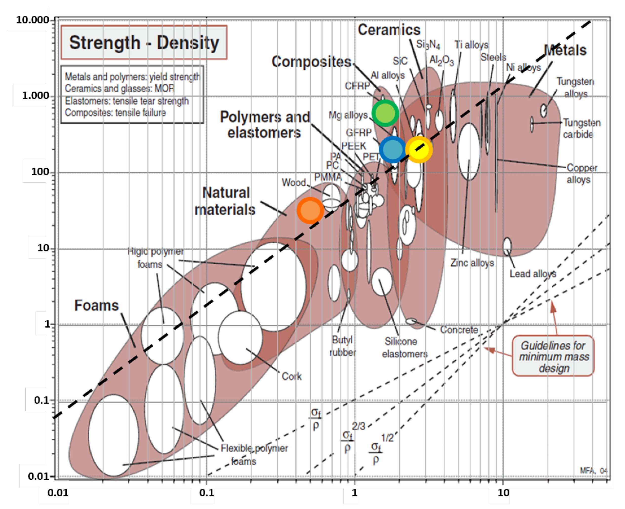
4.4. Variation of the M (Material) Index

Limiting the present analysis to the materials currently adopted in commercial wind turbines, Table 2 collects the M index for glass fiber reinforced polymer (GFRP, blue dot in Figure 8), carbon fiber reinforced polymer (CFRP, green dot), aluminum alloy (yellow dot) and micro-laminar wood. As can be seen from Figure 8, CFRP is the lightest material for a resistant and stiff blade. The here proposed analysis shows, however, that changing the blade material from an aluminum alloy to GFRP will lead to an increase in the WTI by a factor of fewer than 2 times, while the adoption of CFRP will determine an increase of about 3 times.

5. Conclusions

Experimental and analytical evidence show that the inertia of small H-VAWTs is orders of magnitude higher than HAWTs counterparts of comparable size. The consequence is that the acceleration/deceleration capability of an H-Darrieus VAWTs away from cut-in and cut-out wind speeds is partially hampered since the characteristics time of the rotor is much higher than the characteristic time of the gusts. This issue inhibits and makes partially ineffective any turbine control strategy, leading to an insufficient energy harvest and potential structural issues. It was demonstrated that the wind tracking index (WTI) is a highly informative parameter to understand the dynamic behavior of a wind turbine rotor. Its maximization improves the gust tracking capability of the turbine. To be more specific with concern to H-VAWT, a rise of a factor of about 2 to 5 times for the low gusting site and of about 10 to 20 times for a moderate-high gusting site is necessary to provide an acceptable acceleration/deceleration capability. This goal is accomplished by adopting a multi-front design tool. A rational approach is given by the well-known Ashby method, which was demonstrated and adopted in the paper. Its application limits designers’ subjective judgments and the adoption of irrelevant alternatives. This approach consists of expressing the design objective, in the present case, the WTI, by independent performance indexes, namely the E (environment), the G (geometry), the F (functional) and the M (material) indexes, with respect to some constraints (dimensions, stiffness, strength, etc.). The WTI maximization can be pursued by the maximization of one or more of such indexes. The analysis allowed us to conclude that, generally speaking, the H-VAWT accelerating capability results in being penalized under the condition of rotors of relatively large diameters installed in moderate to high gusty urban environments. Mitigation of this setback can be achieved by a specific design approach providing a well-designed blade spar, leading to a WTI improvement of about 5 times. The accurate characterization of blade materials and fabrication can further add a gain of about 1.6 times. Besides high-performing aerodynamics, which is always beneficial, halving the tip speed ratio leads to a gain of about 2 times. This latter choice should be analyzed under the light of considerations on turbine control and other aerodynamic issues. Finally, moving from simple materials, such as wood or aluminum, to composite materials (GFRP or CFRP) will increase the wind tracking capability from 2 times to 3 times, depending on the original material adopted. The combination of such design choices is strongly suggested to improve the performance of small H-VAWTs.
The adoption of variable geometry (blade pitch, and variable diameter) could, in principle, be beneficial to alleviate the long idling times of such rotors, but more investigation is needed in this area in view also of the mechanical complexity and endurance of the blade pitching mechanism as well as the extensible/collapsible arms or blades.
As a general statement, it is clear that, besides the beneficial effect during the starting phase (not addressed in the paper), control systems adopting the variable rotational speed become partly (or totally) ineffective concerning the goal of tracking the optimum power if the WTI parameter remains below one. This means that the actual rotational speed history experienced from a VAWT could differ substantially from the one computed in the design phase. As the fatigue damage depends on the duty cycles accumulated, this could be eventually considered an explanation of the premature and unexpected failure of several VAWTs.

Funding

This research received no external funding.

Institutional Review Board Statement

Not applicable.

Informed Consent Statement

Not applicable.

Acknowledgments

I thank the technicians of the Turbomachinery Laboratory of the University of Trento, Dipl. Eng. Sergio dell’Anna and Filippo Degasperi for the support in the data acquisition and processing, and Alessandra Brighenti for the precious correction support of the text and the drafting of some figures.

Conflicts of Interest

The authors declare no conflict of interest.

Abbreviations

The following abbreviations are used in this manuscript:
A B    blade section area [m 2 ]
A D    rotor swept area [m 2 ]
AEP   Annual Energy Production
AR   rotor aspect ratio H/D
ARA   available rotor acceleration [m/s 2 ]
b   blade section dimension [m]
cblade chord length [m]
C N blade normal force coefficient [-]
C P power coefficient [-]
C T blade tangent force coefficient [-]
Drotor diameter [m]
Eenvironmental index or parameter
Ffunctional index or parameter
F f blade aerodynamic bending force [N]
Ggeometrical index or parameter
Hrotor height [m]
HAWTHorizontal Axis Wind Turbine
H-VAWTStraight-blades Vertical Axis Wind Turbine
I’single blade inertia respect to the axis of rotation [kgm 2 ]
L B blade length [m]
N B number of blades [-]
Mmaterial index or parameter
m b blade mass [kg]
M b blade bending moment [Nm]
k c normal force coefficient magnification factor [-]
K 1 , K 2 , K 3 numerical constants [-]
Q a e r o aerodynamic torque [Nm]
Q g e n electric generator torque [Nm]
Rradius [m]
RRArequired rotor acceleration [m/s 2 ]
Pperformance
ttime [s]
V 0 initial wind speed [m/s]
V free stream wind speed [m/s]
V ˙ free stream wind acceleration [m/s 2 ]
VAWTVertical Axis Wind Turbine
Wblade section modulus [ m 3 ]
WTIwind tracking index [-]
α constant
β constant
Φ f section strength efficiency
λ tip speed ratio [-] Ω R / V
λ o p t optimum tip speed ratio [-]
Ω angular rotor speed [rad/s]
Ω ˙ angular rotor acceleration [rad/s 2 ]
ρ a air density [kg/m 3 ]
ρ B blade density [kg/m 3 ]
σ rotor solidity [-]
σ a d m allowable mechanical stress [Pa]
σ f material safety factor [-]

Appendix A. Collection of Data of Commercial and Prototype H-VAWTs

Table A1. VAWT database.
ParameterUnit[27][47][48][48][48][48][48][48][49][50][51][6][52][53][54][16][55]
Diameter Dm0.61.783.304.607.008.008.5011.002.0017.701.03252.501.038.00266
Radius Rm0.30.891.652.303.504.004.255.5018.850.51512.51.250.5154133
Blade length L B m0.472.492.202.505.704.305.8012.003.4612.81.45618314.8245
Rotor height Hm0.473.742.202.505.704.305.812312.81.45618312.4245
Swept area A D m 2 0.284.447.2611.5039.9034.4049.3132.0062271.504507.51.0319.262430
Rated powerkW-0.73.006.0010.0020.0020.0030-450.20130--1020012
Rated wind speedm/s9.7511.4014.0014.0014.0014.0012.3611.21391011812121212
Rated rot. speed Ω rpm620.5320144.00100.0087.8560.0050.0047.6437233.520027183-8633127
Rotor inertia N B I kg m 2 0.1184041600563012,00015,80023,000--1.5------
Blades number N B -43333333333233333
Cp max--0.320.320.310.3380.3380.34-0.3850.3-0.3-0.475--0.40
Solidity σ -0.50.250.7450.4570.3000.2630.2470.2730.1730.1170.250.1000.480-0.3000.0960.374
Rated λ -22.621.781.722.301.801.802.453.003.452.83.211.62.333.013.743
Chord cm0.0750.150.820.700.700.700.701.000.10.690.0851.250.400.090.400.830.25
I/R 2 ^ kg--49101153250292253--8------

References

  1. Darrieus, G.J.M. Turbine Having Its Rotating Shaft Transverse to the Flow of Current. U.S. Patent US1835018, 8 December 1931. [Google Scholar]
  2. Blackwell, B.F.; Sullivan, W.N.; Reuter, R.C.; Banas, J.F. Engineering development status of the Darrieus wind turbine. J. Energy 1977, 1, 50–64. [Google Scholar] [CrossRef]
  3. Sutherland, H.J.; Berg, D.E.; Ashwill, T.D. A Retrospective of VAWT Technology SANDIA Report; SAND2012-0304, Unlimited Release; U.S. Department of Energy Office of Scientific and Technical Information Albuquerque: New Mexico, CA, USA, 2012. [Google Scholar]
  4. Templin, R.; Rangi, R. Vertical-axis wind turbine development in Canada. IEEE Proc. A Phys. Sci. Meas. Instrum. Manag. Educ. Rev. 1983, 130, 555–661. [Google Scholar] [CrossRef]
  5. FloWind Corporation. Final Project Report: High Energy Rotor Development, Test and Evaluation; SAND96-2205; FloWind Corporation: San Rafael, CA, USA, 1996. [Google Scholar]
  6. Musgrove, P.J. Wind energy conversion: Recent progress and future prospects. Sol. Wind Technol. 1987, 4, 37–49. [Google Scholar] [CrossRef]
  7. Mertens, S. Wind Energy in the Built Environment: Concentrator Effects of Buildings; Multi-Science: Essex, UK, 2006; 169p. [Google Scholar]
  8. Micallef, D.; Bussel, G.V. A Review of Urban Wind Energy Research: Aerodynamics and Other Challenges. Energies 2018, 11, 2204. [Google Scholar] [CrossRef] [Green Version]
  9. Battisti, L.; Dell’Anna, S.; Castelli, M.R.; Brighenti, A. Effectiveness of Wind Turbines in Urban Environment. In Colloquium on Research and Innovation on Wind Energy on Exploitation in Urban Environment Colloquium; Springer: Berlin/Heidelberg, Germany, 2018; Volume 8. [Google Scholar]
  10. Hand, B.; Cashman, A. A review on the historical development of the lift-type vertical axis wind turbine: From onshore to offshore floating application. Sustain. Energy Technol. Assess. 2020, 38, 100646. [Google Scholar] [CrossRef]
  11. Battisti, L.; Benini, E.; Brighenti, A.; Raciti Castelli, M.; Dell’Anna, S.; Dossena, V.; Persico, G.; Schmidt Paulsen, U.; Pedersen, T. Wind tunnel testing of the DeepWind demonstrator in design and tilted operating conditions. Energy 2016, 111, 484–497. [Google Scholar] [CrossRef]
  12. Vita, L.; Paulsen, U.S.; Madsen, H.A.; Nielsen, P.H.; Berthelsen, P.A.; Cartsensen, S. Design and aero-elastic simulation of a 5 MW floating vertical axis wind turbine. In Proceedings of the ASME 2012 31st International Conference on Ocean, Offshore and Arctic Engineering (OMAE2012), ASME, Rio de Janeiro, Brazil, 1–6 July 2012; pp. 1–10. [Google Scholar]
  13. Carstensen, S. Future Deep Sea Wind Turbine Technologies; Technical Report on the Physical Model Experiments [Techn. rep.]; FP7-ENERGY-Specific Programme “Cooperation”: Energy, ENERGY.2010.10.2-1—Future Emerging Technologies for Energy Applications (FET); Available online: https://cordis.europa.eu/project/id/256769/reporting (accessed on 29 August 2021).
  14. INFLOW, Industrialization Setup of a Floating Offshore Wind Turbine. Available online: https://www.inflow-fp7.eu/ (accessed on 25 January 2015).
  15. Tjiu, W.; Marnoto, T.; Mat, S.; Ruslan, M.H.; Sopian, K. Darrieus vertical axis wind turbine for power generation II: Challenges in HAWT and the opportunity of multi-megawatt Darrieus VAWT development. Renew. Energy 2015, 75, 560–571. [Google Scholar] [CrossRef]
  16. Ottermo, F.; Bernhoff, H. An upper size of vertical axis wind turbines. Wind Energy 2014, 17, 1623–1629. [Google Scholar] [CrossRef] [Green Version]
  17. Kjellin, J.; Eriksson, S.; Bernhoff, H. Electric control substituting pitch control for large wind turbines. J. Wind Energy 2013, 2013, 1–4. [Google Scholar] [CrossRef] [Green Version]
  18. Tang, C.; Pathmanathan, M.; Soong, W.; Ertugrul, N. Effects of inertia on dynamic performance of wind turbines. In Proceedings of the Power Engineering Conference (AUPEC’08), Sydney, Australia, 14–17 December 2008; pp. P087.1–P087.6. [Google Scholar]
  19. Islam, M.; Fartaj, A.; Carriveau, R. Analysis of the Design Parameters related to a Fixed-pitch Straight-Bladed Vertical Axis Wind Turbine. Wing Eng. 2008, 32, 491–507. [Google Scholar] [CrossRef]
  20. Brusca, S.; Lanzafame, R.; Messina, M. Design of a vertical-axis wind turbine: How the aspect ratio affects the turbine’s performance. Int. J. Energy Environ. Eng. 2014, 5, 129. [Google Scholar] [CrossRef] [Green Version]
  21. Raciti Castelli, M.; Benini, E. Effect of blade number on a straight-bladed Vertical-Axis Darreius wind turbine. World Acad. Sci. Eng. Technol. 2012, 61, 305e11. [Google Scholar]
  22. Tangler, J.L. The Evolution of Rotor and Blade Design; National Renewable Energy Laboratory: Golden, CO, USA, 2000. [Google Scholar]
  23. Li, S.; Li, Y. Numerical study on the performance effect of solidity on the straight-bladed vertical axis wind turbine. In Proceedings of the Power and Energy Engineering Conference (APPEEC), 2010 Asia-Pacific, Chengdu China, 28–31 March 2010; IEEE: Manhattan, NY, USA, 2010; pp. 1–4. [Google Scholar]
  24. Li, Q.; Maeda, T.; Kamada, Y.; Murata, J.; Furukawa, K.; Yamamoto, M. Effect of number of blades on aerodynamic forces on a straight-bladed Vertical Axis Wind Turbine. Energy 2015, 90, 784–795. [Google Scholar] [CrossRef]
  25. Subramanian, A.; Yogesh, S.A.; Sivan, H.; Giri, A.; Vasudevan, M.; Mugundhan, V.; Velamat, R.K. Effect of airfoil and solidity on performance of small scale vertical axis wind turbine using three dimensional CFD model. Energy 2017, 133, 179–190. [Google Scholar] [CrossRef]
  26. Carrigan, T.J.; Dennis, B.H.; Han, Z.X.; Wang, B.P. Aerodynamic Shape Optimization of a Vertical-Axis Wind Turbine Using Differential Evolution. Int. Sch. Res. Netw. ISRN Renew. Energy 2012, 2012, 528418. [Google Scholar] [CrossRef] [Green Version]
  27. Hara, Y.; Hara, K.; Hayashi, T. Moment of Inertia Dependence of Vertical Axis Wind Turbines in Pulsating Winds. Int. J. Rotating Mach. 2012, 2012, 910940. [Google Scholar] [CrossRef] [Green Version]
  28. Nguyen, L.; Metzger, M. Enhanced energy capture by a vertical axis wind turbine during gusty winds in an urban/suburban environment. J. Renew. Sustain. Energy 2015, 7, 053118. [Google Scholar] [CrossRef]
  29. Nguyen, L.; Metzger, M. Optimization of a vertical axis wind turbine for application in an urban/suburban area. J. Renew. Sustain. Energy 2017, 9, 043302. [Google Scholar] [CrossRef]
  30. Battisti, L.; Benini, E.; Brighenti, A.; Persico, G.; Paradiso, B. A review based on evaluation experiences with ten-years activity in VAWT experimental wind tunnel testing. Green Energy Technol. 2018, 1, 139–154. [Google Scholar]
  31. Ashby, M.F. Materials Selection in Mechanical Design, 3rd ed.; Elsevier Butterworth-Heinemann: Oxford, UK, 2005. [Google Scholar]
  32. Rodriguez, G.A.G.; Rodriguez, A.G.; Payan, M.B. Estimating Wind Turbines Mechanical Constants. In Proceedings of the International Conference Renewable Energies and Power Quality (ICREPQ’07), Sevilla, Spain, 28–30 March 2007; Volume 1, pp. 697–704. [Google Scholar]
  33. Burton, T.; Sharpe, D.; Jenkins, N.; Bossanyi, E. Wind Energy Handbook; John Wiley and Sons, Ltd.: Hoboken, NJ, USA, 2001. [Google Scholar]
  34. Paraschivoiu, I. Wind Turbine Design: With Emphasis on Darrieus Concept; Presses inter Polytechnique: Montréal, QC, Canada, 2002. [Google Scholar]
  35. Homicz, G.F. VAWT stochastic loads produced by atmospheric turbulence. J. Sol. Energy Eng. 1989, 111, 358–367. [Google Scholar] [CrossRef]
  36. Kooiman, S.; Tullis, S. Response of a vertical axis wind turbine to time varying wind conditions found within the urban environment. Wind. Eng. 2010, 34, 389401. [Google Scholar] [CrossRef]
  37. Dutton, A.; Halliday, J.; Blanch, M. The Feasibility of Building-mounted/integrated Wind Turbines (BUWTs): Achieving Their Potential for Carbon Emission Reductions; Tech. Rep., Energy Research Unit Final Report of Carbon Trust Contract 2002-07-028-1-6; Energy Research Unit CCLRC: London, UK, 2005. [Google Scholar]
  38. Cook, N. Designers Guide to Wind Loading of Building Structures; Part 1, Building Research Establishment Report; 1986. Available online: https://www.osti.gov/biblio/5854920 (accessed on 29 August 2021).
  39. Battisti, L.; Benini, E.; Brighenti, A.; Dell’Anna, S.; Castelli, M.R. Small wind turbine effectiveness in the urban environment. Renew. Energy 2018, 129, 102–113. [Google Scholar] [CrossRef]
  40. Campo Eolico Sperimentale di Trento (Experimental Wind Turbine Test Field of Trento), 2006–2018. DICAM (University of Trento, Italy). Available online: http://www.eolicotrento.ing.unitn.it (accessed on 29 August 2021).
  41. Ionescu, R.D.; Ragazzi, M.; Battisti, L.; Rada, E.C.; Ionescu, G. Potential of electricity generation from renewable energy sources in standard domestic houses. Wit Trans. Ecol. Environ. 2013, 176, 245–253. [Google Scholar]
  42. Balduzzi, F.; Bianchini, A.; Carnevale, E.A.; Ferrari, L.; Magnani, S. Feasibility analysis of a Darrieus vertical-axis wind turbine installation in the rooftop of a building. Appl. Energy 2012, 97, 921–929. [Google Scholar] [CrossRef]
  43. Menet, J.L.; Valdes, L.C.; Menart, B. A comparative calculation of the wind turbines capacities on the basis of the Lσ criterion. Renew. Energy 2001, 22, 491–506. [Google Scholar] [CrossRef]
  44. Milborrow, D.J. Performance, blade loads and size limits for horizontal axis wind turbines. In Proceedings of the 4th BWEA Wind Energy Conversion (Cranfield: BHRA), Cranfield, UK, 24–26 March 1982. [Google Scholar]
  45. Siddiqui, M.S.; Durrani, N.; Akhtar, I. Quantification of the effects of geometric approximations on the performance of a vertical axis wind turbine. Renew. Energy 2015, 74, 661–670. [Google Scholar] [CrossRef]
  46. IEC 61400-2:2013. Wind Turbines—Part 2: Small Wind Turbines; IEC: Geneva, Switzerland, 2013. [Google Scholar]
  47. Wind Tunnel Test on Gorlov-Type H-VAWT, DICAM Internal Report. Not published. 2005.
  48. Personal Communication from International Manufacturer (name without disclosure permission), 2015.
  49. Van Bussel, G.J.W.; Mertens, S.; Polinder, H.; Sidler, H.F.A. The development of Turby, a small VAWT for the built environment. In Proceedings of the Global Wind Energy Conference 2004 Session Advanced Small Turbine Technology, Chicago, IL, USA, 30 March 2004. [Google Scholar]
  50. Anderson, J.W.; Brulle, R.V.; Birchfield, E.B.; Duwe, W.D. McDonnell 40-kW Giromill Wind System: Phase I—Design and Analysis; Technical report; Rockwell International Corp.: Golden, CO, USA; Rocky Flats Plant; McDonnell Aircraft Co.: St. Louis, MO, USA, 1979; Volume II. [Google Scholar]
  51. Wang, Y.; Shen, S.; Li, G.; Huang, D.; Zheng, Z. Investigation on aerodynamic performance of vertical axis wind turbine with different series airfoil shapes. Renew. Energy 2018, 126, 801–818. [Google Scholar] [CrossRef]
  52. Bravo, R.; Tullis, S.; Ziada, S. Performance testing of a small vertical-axis wind turbine. In Proceedings of the 43rd AIAA Aerospace Sciences Meeting and Exhibit, Reno, NV, USA, 10–13 January 2005. [Google Scholar]
  53. Castelli, M.R.; Ardizzon, G.; Battisti, L.; Benini, E.; Pavesi, G. Modeling strategy and numerical validation for a darrieus vertical axis micro-wind turbine. In ASME 2010 International Mechanical Engineering Congress and Exposition; Citeseer: Princeton, NJ, USA, 2010; pp. 409–418. [Google Scholar]
  54. Naseema, A.; Uddina, E.; Alia, Z.; Aslama, J.; Shaha, S.R.; Sajida, M.; Zaidia, A.A.; Javedb, A.; Younisc, M.Y. Effect of vortices on power output of vertical axis wind turbine (VAWT). Sustain. Energy Technol. Assess. 2020, 37, 100586. [Google Scholar] [CrossRef]
  55. Solum, A.; Deglaire, P.; Eriksson, S.; Stålberg, M.; Leijon, M.; Bernhoff, H. Design of a 12 kW Vertical Axis Wind Turbine Equipped with a Direct Driven PM Synchronous Generator. In Proceedings of the EWEC 2006-European wind energy conference & exhibition, Athens, Greece, 27 February–2 March 2006. [Google Scholar]
Figure 1. Simplified schemes of wind turbine rotors for HAWT with rectangular (a) and triangular (b) blade planform, as well as for H-VAWT (c).
Applsci 11 09222 g001
Figure 2. Moments of inertia of (H-type) commercial/prototype VAWTs and HAWT, according to diameter (left) and rotor swept area (right).
Applsci 11 09222 g002
Figure 3. Cumulative gust probability of urban sites (a) and W T I as a function of the rotor radius, and three typical wind acceleration rates for some commercial HAWTs and H-type Darrieus VAWTs (b) V ˙ = 0.6 [m/s 2 ], (c) V ˙ = 0.9 [m/s 2 ], (d) V ˙ = 1.20 [m/s 2 ]), for different initial wind speeds V 0 = 5 [m/s], V 0 = 8 [m/s], V 0 = 9 [m/s].
Applsci 11 09222 g003
Figure 4. Solidity vs. tip speed ratio for a collection of VAWTs.
Applsci 11 09222 g004
Figure 5. Blade structural representation.
Applsci 11 09222 g005
Figure 6. The second moment of area I, plotted against section area A (according to Ashby [31]).
Applsci 11 09222 g006
Figure 7. Representation of the blade normal C N and tangential C T coefficients.
Applsci 11 09222 g007
Figure 8. Materials strength [MPa] versus density [kg/m 3 ], elaboration from Ashby [31].
Applsci 11 09222 g008
Figure 9. (left): G = f ( F ) , k = ( 1 + β ) / 3 , C T C N 2 / 3 assumed constant for any turbine model, (right): F = f(D).
Applsci 11 09222 g009
Figure 10. Effect of the tip speed ratio on the power coefficient at different solidities (AR = 5, D = 2 m, c = 0.1 m).
Applsci 11 09222 g010
Table 1. Matrix of reciprocal independence of the performance indexes. o—no dependence, x—possible dependence.
EGFM
E →-ooo
G →o-xo
F →ox-o
M →ooo-
Table 2. Material and shape selection for a light and resistant beam.
Material œ adm ӕ B Index M
[MPa][Mg/m 3 ][Pa 2 / 3 /g/m 3 ]
GFRP2001.819.0
CFRP6001.644.5
Aluminum alloy2002.712.7
Microlaminar wood320.520.2
Publisher’s Note: MDPI stays neutral with regard to jurisdictional claims in published maps and institutional affiliations.

