Article

Design Study of Multi-Rotor and Multi-Generator Wind Turbine with Lattice Tower—A Mechatronic Approach

1
GGS GmbH, Gotthardstrasse 37, 6490 Andermatt, Switzerland
2
Aero Dynamik Consult, Ingenieurgesellschaft mbH, 73765 Neuhausen auf den Fildern, Germany
3
Control Engineering Group, Faculty 1: School of Engineering—Energy and Information, University of Applied Sciences (HTW) Berlin, Wilhelminenhofstraße 75A, 12459 Berlin, Germany
*
Author to whom correspondence should be addressed.
Appl. Sci. 2021, 11(22), 11043; https://doi.org/10.3390/app112211043
Submission received: 10 October 2021 / Revised: 9 November 2021 / Accepted: 15 November 2021 / Published: 22 November 2021
(This article belongs to the Collection Wind Energy: Current Challenges and Future Perspectives)

Abstract

:
New locations for onshore technology, which have not been considered so far, must be developed to increase the total installed capacity of renewable energies, especially wind energy. For this purpose, cost-effective wind turbines, even in difficult-to-access locations, such as mountainous and high-mountainous areas, must be designed. This paper presents a novel wind turbine with a related control system that meets these requirements. The proposed turbine uses a multi-rotor configuration with five rotors arranged in a star shape configuration. Each rotor drive train combines up to 12 generators in a maintenance-friendly multi-generator concept. A suitable observer-based control for load mitigation in the full-load region is proposed for the multi-rotor and multi-generator design. Simulations are used to demonstrate the applicability and practical benefits of this concept.

1. Introduction

Achieving the ambitious goal of reducing CO2 production, the share of renewable energy sources in power generation must be significantly increased in all countries worldwide. In terms of wind power generation, this means re-powering of existing older turbines and installing new high-power turbines with longer blades (larger rotor areas). The extreme increase to up to 15MW is primarily intended for offshore wind turbines [1]. However, it has limitations in terms of logistics, i.e., transport, installation, and maintenance when expanding onshore wind energy. The limits listed are even more apparent when turbines are to be installed in mountainous areas [2]. Therefore, a concept study of multi-rotor and multi-generator wind turbine with a lattice structure for difficult-to-access wind locations is presented (Figure 1).
The concept of multi-rotors, i.e., the substitution of a single rotor by an area equivalent number of three up to seven rotors, is not a new idea [3]. In the 1980s and 1990s, the Dutch manufacturer Lagerwey Wind developed several multi-rotor systems. These find promising solutions to major technical problems such as yaw and rotor integration. Satisfactory performance was claimed for one particular six-rotor system, but customers preferred a conventional system. However, this concept is undergoing a renaissance due to increasing cost pressure. The results in [3] show that four 5-MW rotors cost 80% of a single 20 MW rotor. The need to reduce energy costs also means that wind turbines should produce more power per turbine, which leads to very high loads on single-rotor wind turbines because the rotor blades must also be suitably long. For this reason, new research and development activities have been taking place since the beginning of the millennium. In the year 2010, a multi-rotor wind turbine consisting of seven rotors was tested in a NASA laboratory and delivered encouraging results for future work [4]. Furthermore, a prototype multi-rotor system with four rotors was designed by the manufacturer Vestas. It consists of four commercial V29 units, which are mounted on one support structure. The developments so far have been driven by the advantage of the scaling law [5,6], according to which the total sum of rotors and drive trains of the multi-rotor system can have significantly less weight and cost compared to an equivalent single-rotor turbine.
However, the success of a new design must also take into account other aspects [7]. The concept presented in this paper rather focuses on simplified installation, maintenance and the related load mitigation automatic control scheme. In addition to the multi-rotor design, the support structure (lattice mast and support arms) and the drive train as a multi-generator system are designed to allow installation and maintenance in difficult terrain. In addition to the scaling law effect of multi-rotors, three other advantages of the concept presented here are important to consider:
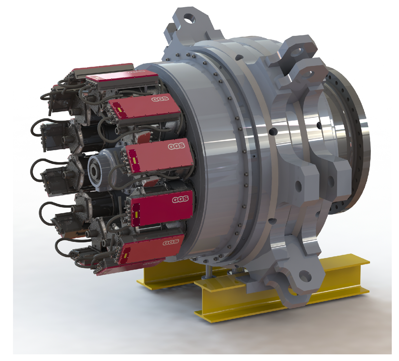
  • Standardization of the multi-generator drive train: Components such as the single high-speed generators of the multi-generator drive-train in the power range of car/truck drive motors (200–220 kW) will allow for stable serial production at a size comfortably within industry experience. It will lead to very substantial cost reductions and improvements in reliability.
  • Fault tolerance/Resilience: Faults on an individual rotor, generators, or power electronics do not affect the operation of the entire plant. The wind turbine system can continue to produce power in the occurrence of individual faults. In [8], a fault-tolerant control concept for the multirotor system was presented for achieving this.
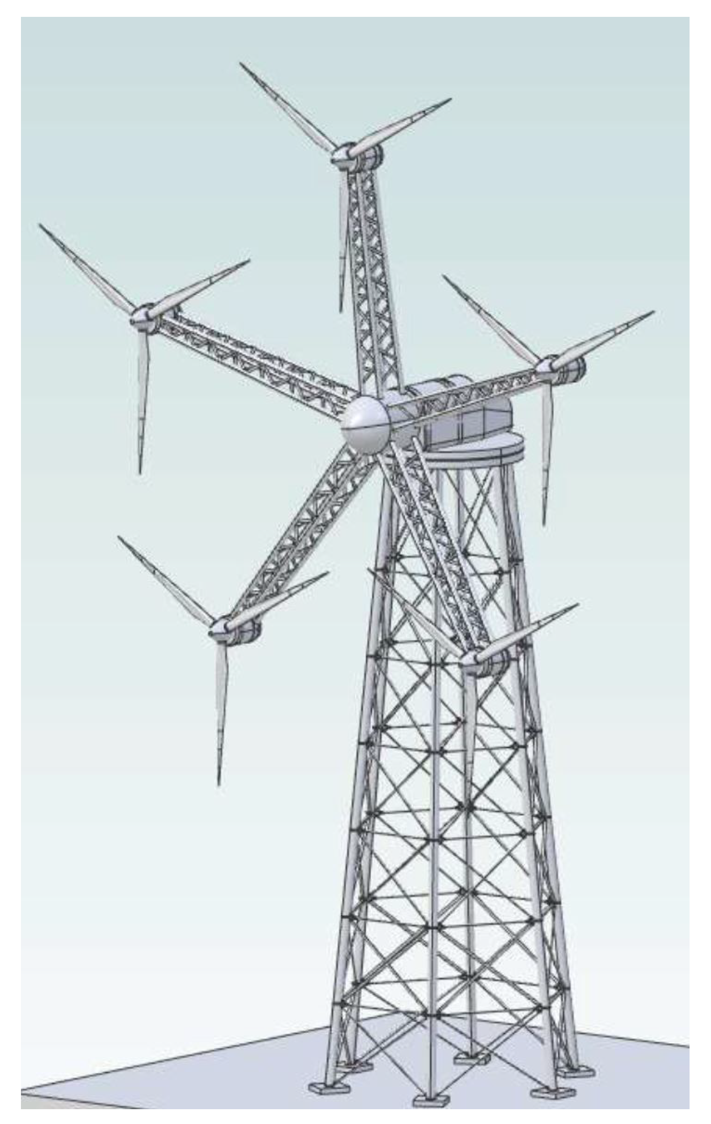
  • Maintenance: The simplified maintainability results from the ability to disassemble the components of the drive train and the option to use an on-board crane and on-board elevator. The star of the five rotors could be turned so that the nacelle to be maintained remains on the six o’clock position (see Figure 1).
As it is seen in Figure 1, the wind power plant is entirely built from a lattice structure. The whole turbine, such as the main tower and support arm of each nacelle/rotor unit, is constructed by a lattice steel structure. It should be noted that for the design, manufacturing, and assembly of the mechanical structure, one can draw on the long experience of steel transmission and telecommunication towers. The choice of the presented lattice structure is based on the comparison of the various bracing systems from [9]. Calculation details and engineering design studies are presented in Section 2.1. Another essential aspect mentioned before is the model-based automatic control concept for mechanical load mitigation of multi-rotor turbines. Due to the non-uniform wind speed distribution over the entire rotor surfaces, observers are designed to estimate each rotor’s effective wind speed. Based on the results of wind speed estimation proposed in [10] and a load mitigation controller for single rotor turbines in [11], in this study, a model-based controller for a multi-rotor wind turbine is presented.
Only a few research studies deal with multi-rotor systems, especially with the holistic mechatronic aspect: a review of the research and industrial multi-rotor research projects was given in [5]. Comparison of the electrical topology (generator–converter interconnection) of multi-rotor wind turbines was presented in [12]. In this regard, eight electrical topologies were proposed and analyzed in terms of mass, cost efficiency, number of components and reliability. These differ in the combination of DC-DC and DC-AC components. A promising approach is to combine the DC links of each rotor–generator–converter unit in one bus system. However, cost advantages only arise when the DC/DC is produced in large quantities. A similar aspect was studied in [13], where different options for multi-rotor wind turbine grid connection were considered. Analogous to the interconnection of wind turbines in a wind farm, star-shaped, and ring-shaped interconnections were investigated. However, a final evaluation is still missing.
Even in terms of aerodynamic design, the multi-rotor concept offers advantages. In [14], a combined numerical (using Large Eddy Simulation) and analytical modeling study of a 4-rotor wind turbine configuration was carried out. It was shown that the 4-rotor wind turbine leads to faster wake recovery compared to the conventional 1-rotor configuration. This adds the potential for multi-rotors to be arranged more compactly in a wind farm. Furthermore, it offers the possibility to reduce wake-induced fatigue loads. Scaling aspects concerning manufacturing, installation, and operation were addressed in [3,7]. A cost model comparing multi and single rotor configurations was proposed in [7]. It was shown that the installation costs for multi-rotors are 83.47% of single rotors. Furthermore, the costs for multi- and single rotor systems with respect to power production and rotor mass were investigated in [3]. It was shown that the results are sensitive to many assumptions and that the multi-rotor is more cost-effective under this reasonable hypothesis. Therefore, the authors suggested that the multi-rotor concept needs more intensive research to analyze the performance in terms of their suitability to replace the single rotor wind turbine. The same conclusion was reached by the authors of [5]. However, they also claimed that standardization in manufacturing and installation can lead to cost reductions for multi-rotors. In summary, in all areas of wind energy technology, research and development activities for multi-rotor have again increased in the recent years. The complexity seems to be controllable by new calculation methods and manufacturing technologies. Studies with cost models show that wind turbines’ energy cost is reduced by up to 80%.
This paper is organized as follows: Section 2 presents the control objectives and describes the multi-rotor wind turbine under investigation. In particular, all subsystems such as the mechanical structure of the main tower and support arms, the aerodynamic models of the rotor torque and thrust force, and the multi-generator drive train are addressed. The methods, including the wind speed observer design, the derivation of the control-oriented model, and the scheme of load mitigation and power controller, are proposed in Section 3. Section 4 presents the results of the design such as observers and controller gains and simulation runs for different scenarios. Finally, in Section 4, the results are evaluated for the upcoming technical implementation of the new proof-of-concept.

2. Plant Description and Control Objectives

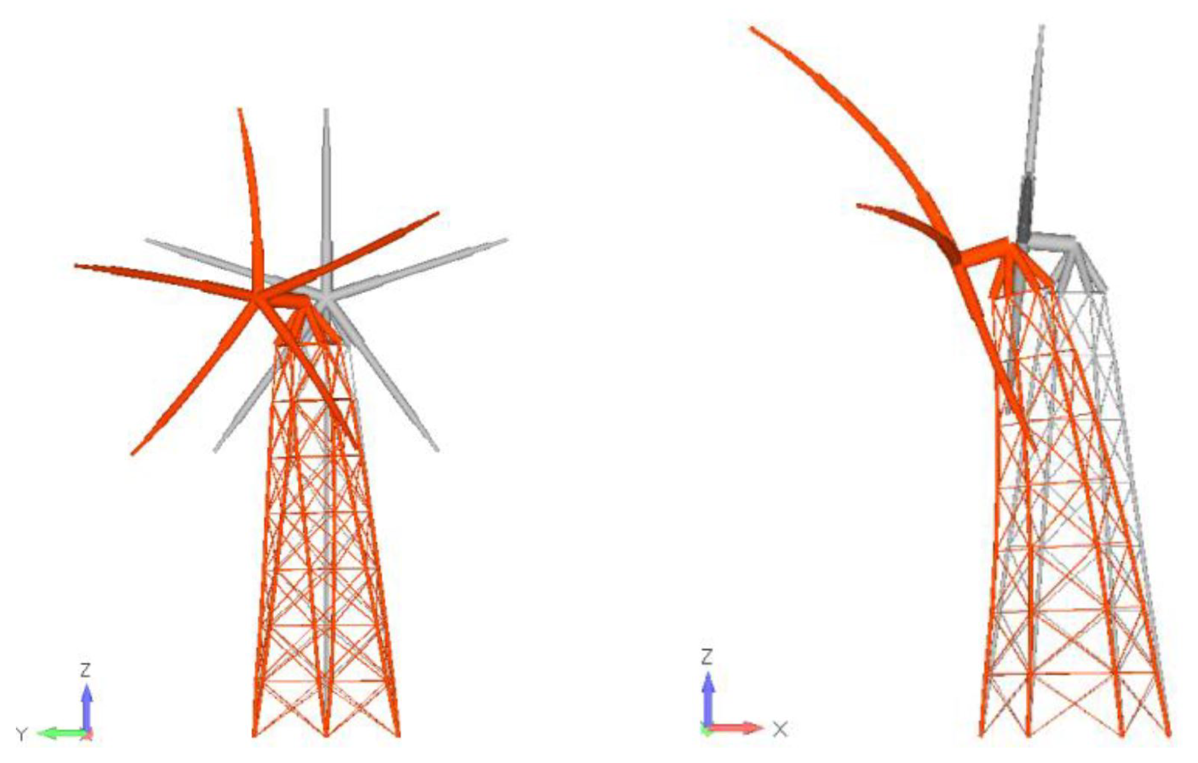
2.1. Structure of Lattice Main Tower and Support Arms

The proposed design study consists of five 100-m diameter rotors attached to a central tower in a star shape via arms (see Figure 1). The hub heights of the individual rotors are between 150–300 m. The advantages of this wind turbine concept are the high rated power with minimal space requirements and reduced transport costs due to standard sizes of components. For example, all components, including the generators and rotor blades, can be transported by cable cars to difficult-to-reach mountain regions.
In the first variant, the rotor arms are designed as cantilevers. Since this led to very high bending moments at the central hub, bracing between the arms was investigated in a second variant. In the third and fourth variant, the arms are designed as a lattice structure. The variants differ in the connection of the arms to the central hub. The mechanical design of the structure is based on the FEM method, where the tower (Variant 1–4) and lattice structure of the arms (Variant 3, 4) can be designed with a selection of beam elements with diameters between 50–8000 mm and wall thickness up to 100 mm. The actual choice of beam elements is made with an iterative FEM algorithm, where the calculated stresses in each beam element are a selection criterion. In case the stress exceeds a threshold value, the beam is strengthened. In case it falls below, the cross-sectional area of the beam is reduced. Another design criterion is the natural frequencies of the structure. The tower is reinforced until the lowest natural frequency exceeds a threshold value. After a few iterations, this results in an optimized tower geometry. For the first variant with lattice tower and arms of steel towers (cantilevers), two eigenmodes are shown in Figure 2. The left picture shows the torsional eigenmode with a frequency of f 0 , t = 0.1965 Hz and the right one, the nodding eigenmode of f 0 , n = 0.2703 Hz. For active mitigation of the nodding eigenmode, a model-based control is presented in Section 2.5, in which the motion of each arm tip (position of the nacelles) is described by means of an equivalent mass-spring-damper model.

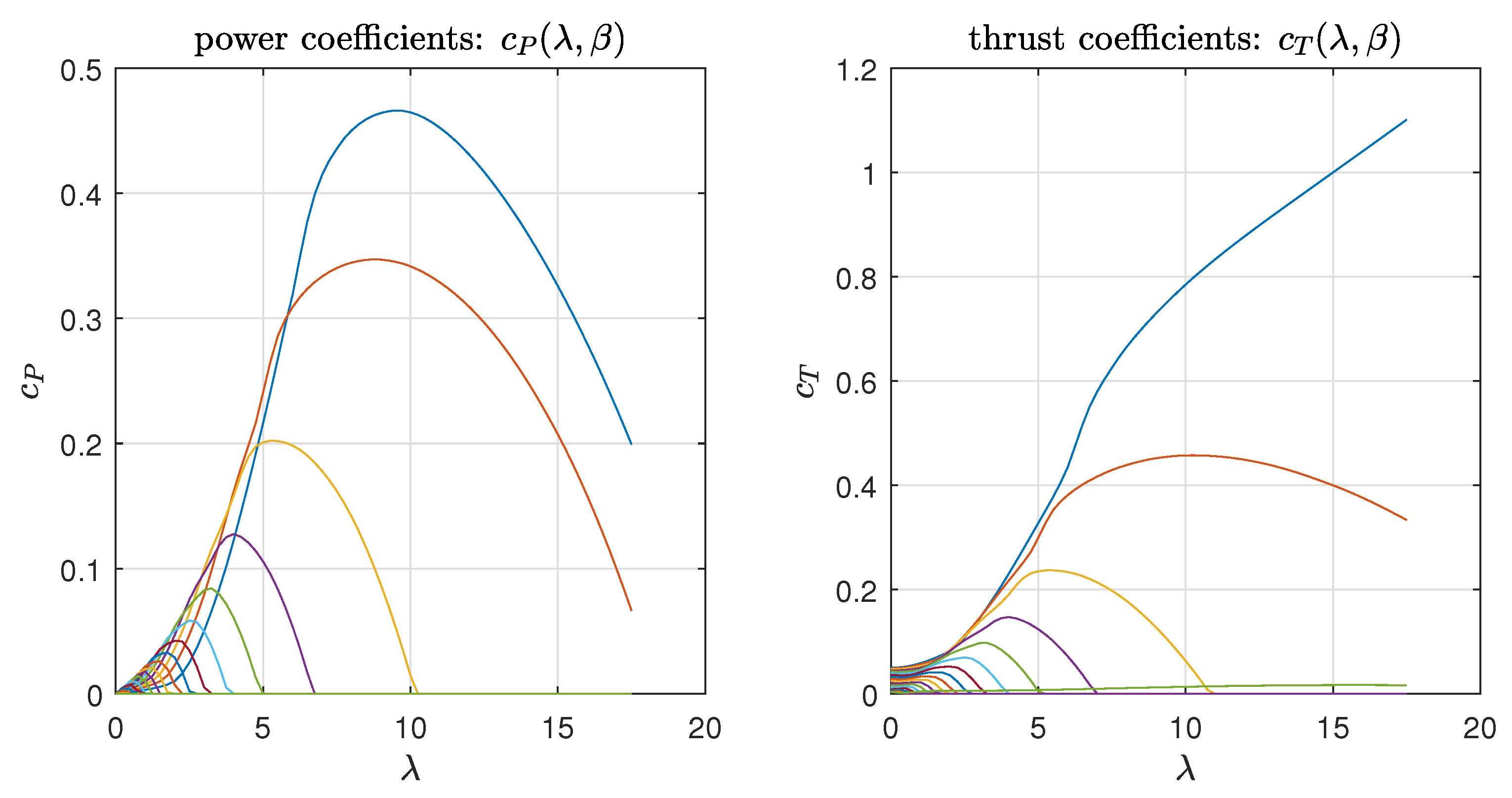
2.2. Aerodynamics of Single Wind Turbine Rotor

The power characteristics of multi-rotor wind turbines result from the same underlying physics as single-rotor turbines. Following the flow tube theory, the wind power P w of a free airflow along an assumed flow tube of radius R and flow velocity v is given by
P w = 1 2   ρ   v 3   π   R 2   ,
where R denotes the rotor radius and ρ is the air density. A rotor inside the flow tube generates a power P r from the wind power P w which depends on the so-called power coefficient c P :
P r = P w   c P λ , β = 1 2   ρ   v 3   π   R 2   c P λ , β   ,
where β denotes the collective blade-pitch angle of each rotor, v is the wind speed far in front of the rotor, and λ is denoted as the tip speed ratio defined by
λ = ω r   R v   .
Based on the rotor power P r = T r   ω r , the rotor torque T r can be obtained as well
T r = 1 2   ρ   v 2   π   R 3   c P ( λ , β ) λ = 1 2   ρ   v 2   π   R 3   c Q ( λ , β )   ,
where c Q denotes the torque coefficient and the c P coefficient curve, also called c P - λ curve. For the wind turbine under study, Figure 3 represents the c P - λ curve. This shows the characteristic non-monotonic profile with a maximum in in the middle and c P -values approaching zero for small and large λ . In accordance to Betz [15], the theoretically achievable maximum value of the power coefficient is c P , m a x = 16 27 . It should be noted that c P , m a x is only reachable for an ideal rotor, without:
  • Airfoil losses at the rotor blade sections due to drag forces;
  • Tip losses due to flow around the blade tip;
  • Wake vortex losses due to the downward wake vortex rotation.
The thrust force on the structure in wind direction for each rotor is quantified by
F T = 1 2   ρ   π   R 2   v 2   c T ( λ , β )   ,
where c T denotes the thrust force coefficient as a function of the tip-speed ratio and blade-pitch angle, which is illustrated in the right diagram of Figure 3. Note the very strong influence of the pitch angle change from 0 to 5 degree. This allows the thrust force to be controlled in order to actively mitigate loads.

2.3. Multi-Generator Drive Train

The multi-generator drive train of each rotor illustrated in Figure 4 consists of a two-stage epicyclical split gear, a spur gear for power distribution, and epicyclic split gears directly connected to each of the twelve generators. Each generator feeds its AC-DC converter (see the rectangular devices in Figure 4). All converters are connected via DC bus to a common grid-side DC-AC converter (not shown in Figure 4).
For the control scheme presented, the generator torques of the individual generators are aggregated to a total torque T g . The reference torque is divided equally between all 12 generators. In this study, the reference torque is divided equally among all 12 generators. However, over-actuation could also be used to switch off individual generators at partial load or in the event of a fault. A concept that is fault-tolerant in case of a generator fault was presented in [8]. This will not be discussed further here, but is an important approach to consider in a future study along with the multi-rotor system.

2.4. Control Objectives

Wind turbines are operated at the partial-load and full-load operating region. Below the design or rated wind speed v r a t e d , the rotor speed ω r is lower than the rated speed ω r , r a t e d . This operating region is called the partial-load region because the turbine power produced is less than the rated power P r , r a t e d . The main control objective in this operating region is power optimization. If the wind speed exceeds the design wind speed, the power is actively limited to P r , r a t e d . Therefore, this region is referred to as the full load region.
To achieve the optimal power in partial load, the rotor speed ω r must be adjusted by the generator torque so that λ corresponds to the value at which the maximum c P value is reached (see the c P - λ curve of Figure 3). Formally, the control objective can be formulated as follows
max λ   c P ( λ , β = 0 ) = c P ( λ o p t , β = 0 ) = c P , m a x   , λ o p t = R   ω r v   .
This means that the optimum must be set dynamically by varying the rotor speed due to the generator torque. It should be noted that the wind speed in front of the rotor is not known. Therefore, an observer concept is presented in Section 3.2. For a further detailed study, let us consider the simplified equation of motion of the multi-generator WT drive train:
ω ˙ r = 1 J T r ( ω r , v , β = 0 ) n g   T g   ,
with
T g = i = 1 N e = 12 T g , i
as the sum of all generator torques, where N e = 12 denotes the number of generators for each rotor and T g , i denotes the torque of each generator (see Figure 4). Furthermore, in Equation (7), the parameter J denotes the total inertia of the drive train and n g the entire gearbox transmission from the low-speed rotor axis to the high-speed individual generator shafts. Note that the inertia J summarizes the mass inertia of the shaft, hub, generator, the effective mass inertia of the gear box and the mass inertia of the rotor blades around the rotor axis. Based on the reasonable assumption of a stiff shaft, the rotor speed is proportional to the generator speed and results from the relation
ω r =   ω g n g   ,
where n g (also in Equation (7)) denotes the whole ratio between the high-speed shaft of each machine of the multi-generator design (see Figure 4) and the low-speed shaft of the rotor.

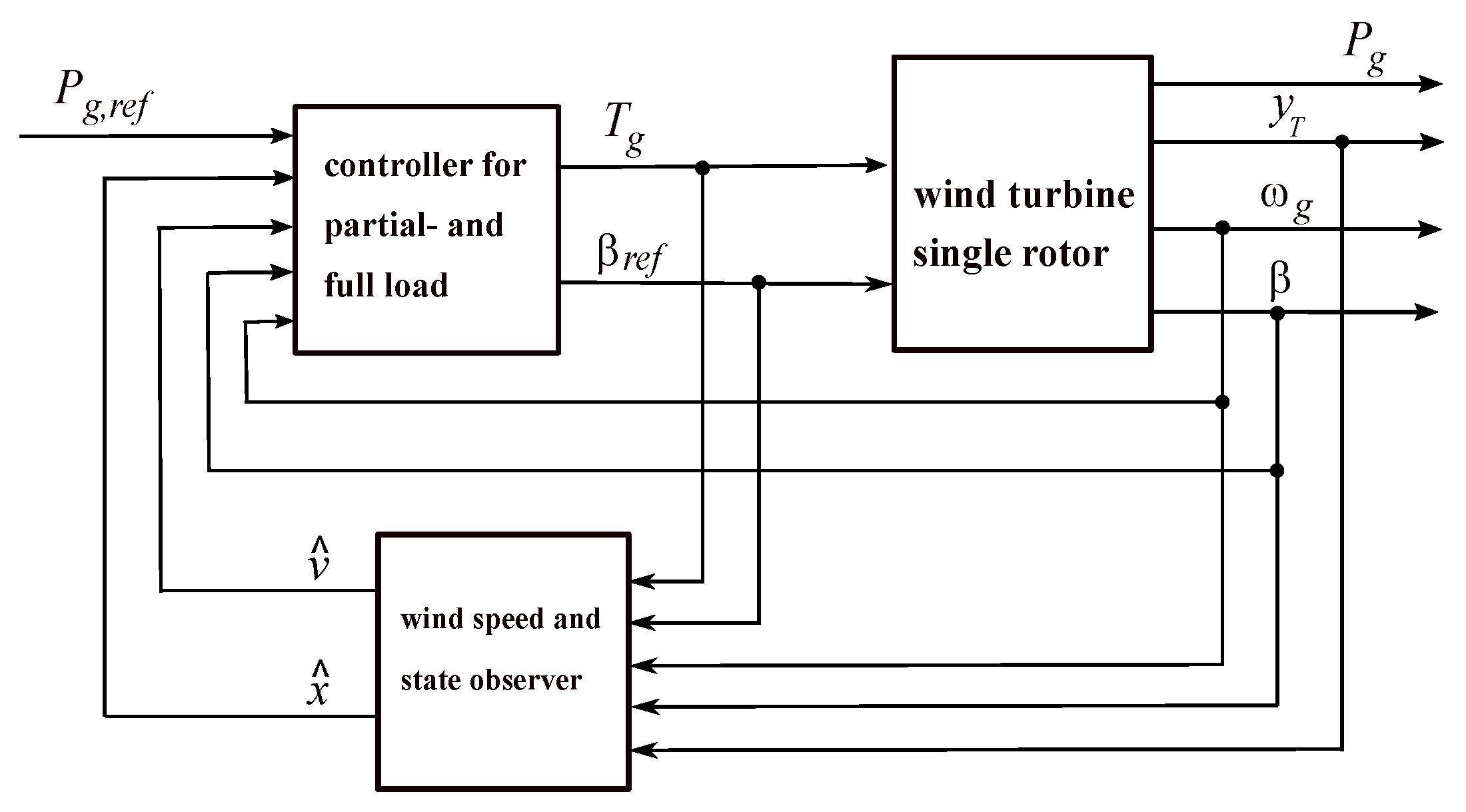
2.5. Control Scheme for Power Control and Load Mitigation

The proposed control system for multi-rotor wind turbines consists of an observer-based nonlinear controller with state feedback. An overview of the complete system consisting of the controller, observer and the plant with all process variables is shown in Figure 5.
A key component of the concept is the observer, which is used to estimate the effective wind speed denoted as v ^ in front of each rotor separately. The controller can specifically affect the forces and torques acting on each rotor and support arm with the rotor-specific estimation of the wind speed. Manipulated variables corresponding to the controller outputs are the collective reference blade-pitch angle per rotor β r e f and aggregated reference generator torque T g for the multi-generator system. It should be noted that no distinction is made between a reference and actual generator torque because the fast internal dynamics of the generator control can be neglected. Measured for control and observation is the aggregated generator speed ω g , the relative deflection of the support arm denoted by y T and the collective pitch angle β (see the output of the wind turbine block). In addition, for higher-level primary frequency control of the grid, the output generator power P g is measured, and a reference power P g , r e f is sent to the controller. This allows the wind turbine to be operated at reduced power (so-called deloading or active power control) if the required power is less than the current power fed into the grid.

3. Methods

3.1. Reduced Dynamic Model for Observer and Controller Design

The reduced dynamic model describes two rotor degrees of freedom, the rotor rotation and relative cantilever deflection in addition with the pitch system dynamics. The rotor rotation is already modeled with the motion equation in Equation (7) and the aerodynamic torque (Equation (4)). Second degree of freedom is described by the equivalent model of cantilever deflection with a spring-mass-damper system and the external thrust force F T (Equation (5))
m T   y ¨ T = d T   y ˙ T k T   y T + F T   ,
where m T denotes the effective mass of nacelle-cantilever motion, d T is the effective fore-aft cantilever damping constant, and k T denotes the effective cantilever fore-aft stiffness parameter. The pitch system model describes the dynamics of controlled electric blade-pitch systems as a a first-order model
β ˙ = 1 τ β β + 1 τ β β r e f   ,
where β r e f denotes the demanded pitch angle, τ β the time constant of the pitch model. Additionally, for controller validation, a rate limitation is still taken into account. The rate is typically limited to 8 / s to avoid excessive loads in the pitch bearing and blade root. With the introduction of the state vector
x = (   y T   ,   y ˙ T   ,   ω r   ,   β   ) T = (   x 1   ,   x 2   ,   x 3   ,   x 4   ) T
the input vector
u = (   T g   ,   β r e f   ) T = (   u 1   ,   u 2   ) T   ,
and output vector
y = (   y T   ,   ω g   ,   β   ) T = (   y 1   ,   y 2   ,   y 3   ) T   ,
we obtain from Equations (4), (5), (10), and (11) the wind turbine model for observer and controller design with the state differential equations
x ˙ 1 = x 2   , x ˙ 2 = k T m T   x 1 d T m T   x 2 + 1 2   m T   ρ   π   R 2   v 2   c T ( λ ( v , x 3 ) , x 4 ) )   , x ˙ 3 = 1 2 J ρ   π   R 3   v 2   c Q ( λ ( v , x 3 ) , x 4 ) ) n g J   u 1   , x ˙ 4 = 1 τ β x 4 + 1 τ β u 2   ,
and output equation
y 1 = y T = x 1   , y 2 = ω g = n g   x 3   , y 3 = β = x 4   .
Based on this state space model, a Takagi–Sugeno (TS) formulation [16] is formed for the controller and observer design with convex-optimization techniques using linear matrix inequalities. Details on the detailed derivation are given, for example, in [11]. The proposed TS model, equivalent to Equations (15) and (16) in a predefined operating region, is specified separately for the partial-load, and the full-load operating region is given as
x ˙ = i = 1 N r = 8 h i ( z )   A i   x + B i   u , x 0 = x ( t 0 )   , y = C   x
where h i ( z ) is the i = 1 , , N r scalar-valued membership function that represents the contribution of each linear sub-system with { A i , B i , C } to the total nonlinear model in TS form. The nonlinear behavior in Equation (17) is determined by the weighting of the linear systems via the so-called premise variable z which in this case is defined by
z = (   ω r   ,   β   ,   v   ) T   .
The A i , B i matrices, and h i functions are obtained by applying the Sector-Nonlinearity (SN) approach. The model derivation for single rotor turbines using the SL approach was published first in [17]. We apply this concept to multi-rotor turbines, where each rotor is first controlled in a decentralized way. In a second design step, the mechanical stiffening of the cantilevers is taken into account in the controller design via connected spring–mass couplings.

3.2. Effective Wind Speed and State Observer

The presented observer structure is based on the previously introduced wind turbine model which is extended by a disturbance model of the effective wind speed to be estimated. In control theory, this is a recognized method in which unknown inputs (such as wind speed in this case) are combined with a model and measurements to form a disturbance observer [10]. To do this, we start with the disturbance model
v ˙ = 1 τ v v + 1 τ v   v 0
proposed in [18], where τ v denotes the time constant of disturbance model and v Σ represents the mean wind speed. With the assumption that the mean values as reference wind speed change slowly, it can be calculated over an appropriate time period T p (e.g., 10 min) from the anemometer sampled wind measurement
v Σ = i = 1 N s v ( t i   T s )   , T b = N s   T s   ,
where T s denotes the sampling time and N s the number of samples in T b . Furthermore, the mean wind speed can be obtained by additional prior knowledge by means of static maps which contain relations of the equilibrium points
v 0 = v 0 ( β , ω g ) | { β i e , v i e }   .
where v Σ = v 0 . The actual model for the wind speed and state estimator is then obtained by expanding the state vector (12) by
x ˜ = (   x T   ,   v   ) T   .
Hence, from Equations (17), (19) and (22), the augmented state space observer model results in
x ˙ = i = 1 N r = 8 h i ( z )   A ˜ i   x + B ˜ i   u , x ˜ 0 = x ˜ ( t 0 )   , y = C ˜   x
with
A ˜ i = A i 0 4 × 1 0 1 × 4 1 τ v   , B ˜ i = B i 0 1 × 2   , C ˜ = C 0 3 × 1   .
Based on this model, an observer can now be specified in TS form also known as TS Luenberg observer
x ˜ ^ ˙ = i = 1 N r = 8 h i ( z ^ )   A ˜ i   x ˜ ^ + B ˜ i   u ˜ + L i ( y y ^ )   , y ^ = C ˜   x ˜ ^   ,
with z ^ = (   ω ^ r   ,   β   ,   v ^   ) T . The observer provides the required estimate of the effective wind speed in front of the rotor and the estimated states of the wind turbine divided into five individual rotors
x ˜ ^ = (   x ^   ,   v ^   ) T   ,
which are directly fed into the two control laws for the partial-load and full-load operating region, see the block diagram in Figure 5.

4. Results

The numerical results are presented below based on the implementation in Matlab/Simulink (R2020a). For a realistic calculation of aerodynamics, the aeroelastic code FAST v8.16 from NREL is used [19].

4.1. Control Laws for Partial-Load and Full-Load Operating Region

Before we come to the simulation results, the control laws are briefly presented. Details of the design approach are proposed in [11], for example. The control law in a parallel distributed compensation (PDC) scheme consists of a state and integral error feedback:
u = i = 1 N r h i ( z )   K x , i   Δ x + i = 1 N r h i ( z )   k I , i   x I   ,
where
x I = 0 t ω r , r e f ω r d τ = 0 t e   d τ
with the control error e = ω r , r e f ω r and the premise variables summarized in z = (   x T   ,   v ^   ) T . The state feedback of the full-load region controller is given as
Δ x = ω r ω r , r e f β = x 1 x 1 , r e f x 2   ,
For the partial-load region, since the pitch angle is zero, only the rotor speed is fed back as a state.
Δ x = ω r ω r , r e f = x 1 x 1 , r e f   .
The control law for power optimization (partial-load region) and limitation (full-load region) differ in the control variable u = { T g , β r e f } and in generation of the reference value ω r , r e f to be tracked. Thus, let us take a look at this in detail:
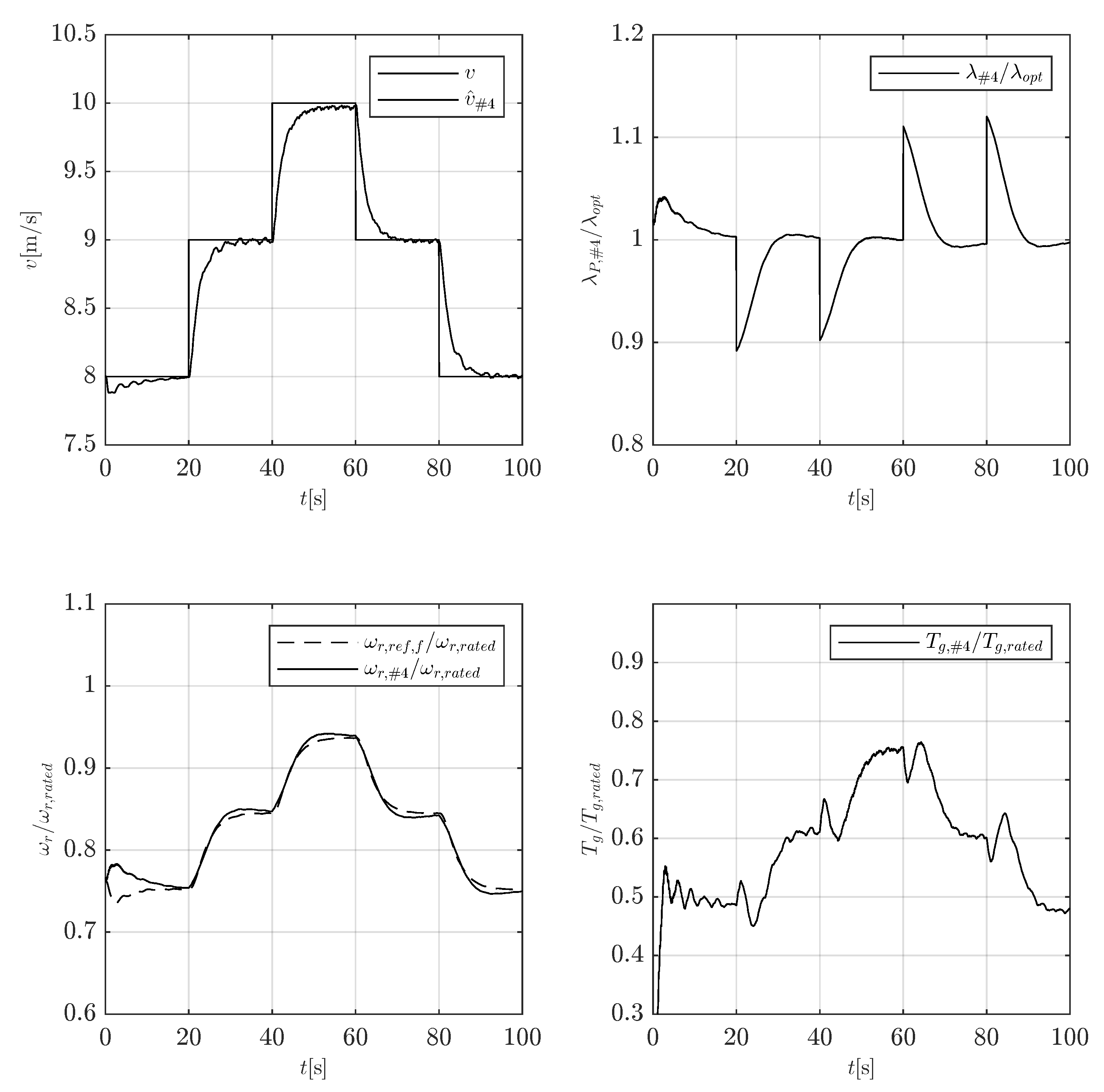
  • The partial-load controller adjusts the generator torque u = T g to track the rotor speed following ω r , r e f = λ r a t e d R   v with λ r a t e d = λ o p t , cf. Equation (3) where the pitch angle is set constantly to zero β r e f = 0 . According to Equation (2), this results directly from the control objective of maximizing the rotor power P r by tracking the rotor speed so that an optimum value c p , m a x = c P ( λ o p t ) is reached. Here, the dynamics is limited by the achievable actuating variable effort (generator torque).
  • On the other hand, the controller of the full-load region adjusts the pitch angle set point β r e f 0 so that the rotor speed is kept to its rated value, i.e., ω r , r e f = ω r , r a t e d . To obtain rated power P g , r a t e d if v > v r a t e d , the generator torque is simultaneously kept to its rated value T g = T g , r a t e d .
Note that the synthesis of control law (27) for both operating regions can be converted separately into a convex programming problem written in terms of linear matrix inequality (LMI) conditions proposed in [11].

4.2. Simulation Results in the Partial-Load Region

An artificial profile of the wind speed in front of the rotor is used to validate the control law in the partial-load region. This consists of discrete wind steps to evaluate the convergence rate of the power optimization for each rotor with Equation (27).
The simulation results are shown in Figure 6. The true effective wind speed v ( t ) and related estimation v ^ ( t ) are given in the left-upper sub-figure. Note that the v ( t ) -curve describes the entire homogeneous wind field in the rotor plane, which means that the wind speed is constant over the whole rotor area. It can be clearly seen in Figure 6 that the estimated wind speed converges relatively slowly to the true speed. However, this is not a disadvantage in terms of controller performance. Since the reference rotor speed ω r , r e f to be followed is calculated with the estimated wind speed (which is therefore also adjusted relatively slowly, see the left-lower sub-figure)
ω r , r e f = λ o p t R   v ^
using the observer (25), the reference trajectory can therefore be followed with the limited manipulated variable action (generator torque T g T g , r a t e d ). This is clearly shown in the right-lower sub-figure, where the constraint of T g / T g , r a t e d = 1 is not reached. How well the control objective of power optimization is met can be seen from the normalized λ / λ o p t curve. After each wind speed jump (t = 20 s, 40 s, 60 s, 80 s), the rotor speed is adjusted in such a way that after approx. 10 s the optimum λ value, thus, the maximum c p value and, therefore, the maximum possible power is produced again.

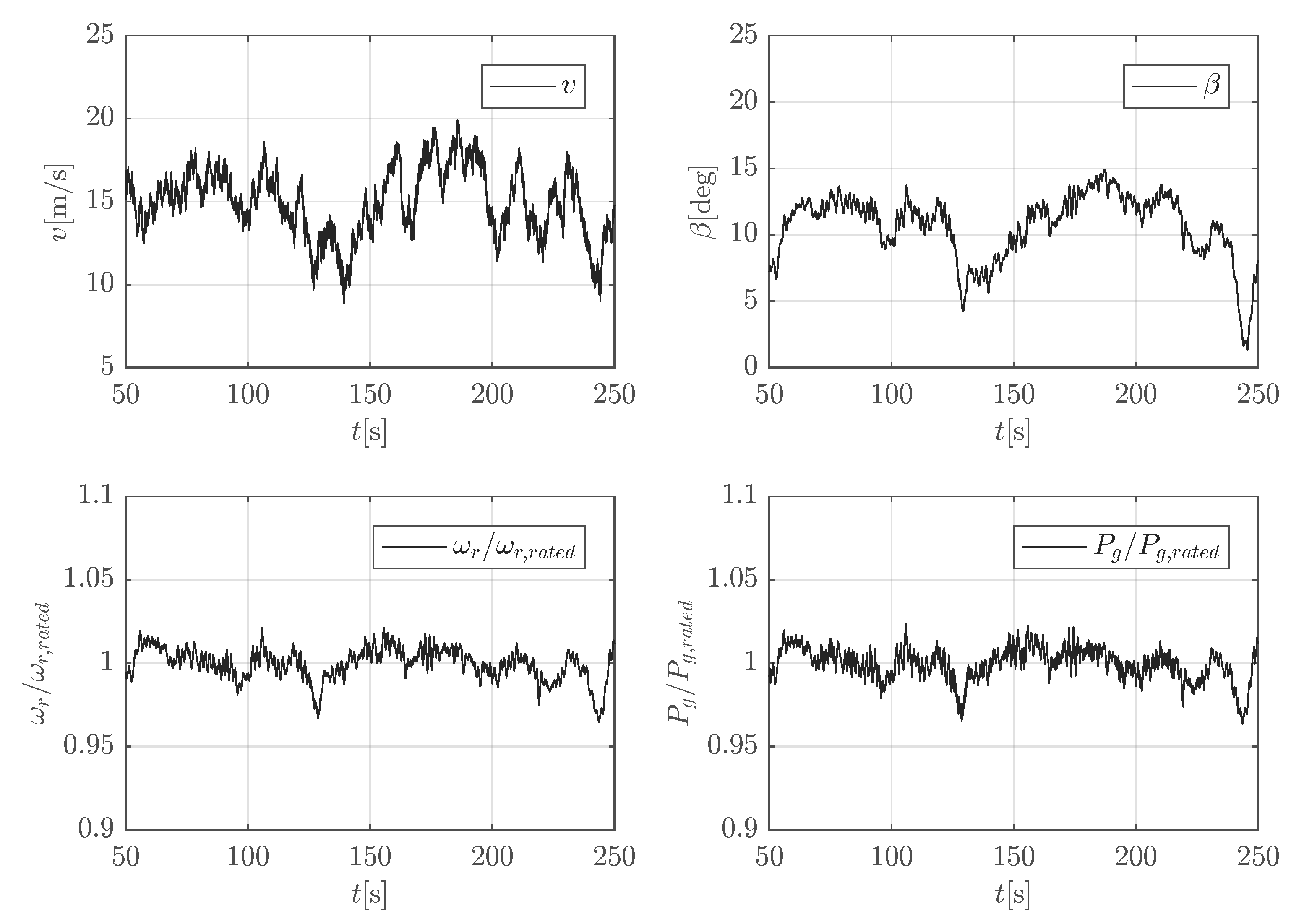
4.3. Simulation Results in the Full-Load Region

Simulations results in the full-load region using a realistic turbulent wind speed in front of the rotor are shown in Figure 7. However, as with the partial load-region, we initially assume a homogeneous wind field. One can clearly see that due to the turbulent wind speed above, the rated wind speed, the collective blade-pitch angle is constantly adjusted (output of the controller) in order to limit the generator power to the rated value. The rotor speed and generator power are shown in relations to the nominal values.
It is worth mentioning that the reaction of the control to the wind speed drops at t = 140   s . This sudden wind drop causes a rotor speed decrease, which is compensated by the fast pitch angle correction due to the controller action following Equation (27).

5. Conclusions

A multi-rotor wind turbine with multi-generator drive trains was presented. Both the mechanical structure with the calculation of eigenmodes and a control scheme with simulation results were proposed. The control system uses a wind speed observer-based state feedback scheme for each rotor to consider wind speeds, which vary significantly over the entire altitude. The wind speed observer model and control law was presented, and more detailed controller design references were given.
The results of a purely mechanical structural analysis and mechanical FEM design were presented in the first part. Then, in the second part, a control structure was proposed that mitigates the loads on the tower structure. This approach is based on the mechatronic idea using the synergy of information processing, electronics (software and hardware of the controller), mechanical/aerodynamic modeling, and numerical calculation (FEM and ODE solver). A controller structure was proposed, which acts both in the partial-load operating region by adjusting the generator torque and in the full-load by changing the pitch angle. In both regions, estimating the non-measurable effective wind speed in front of the rotor is utilized. For the partial-load region, the reference speed of the control is calculated, which is necessary to achieve the optimum tip speed ratio, respectively, the maximum power coefficient. In contrast, the full-load controller uses the wind speed estimate to calculate the current scheduling vector and to adapt the controller coefficients via the weighted sum of the controller gains K x , i and k I , i . Simulation results with artificial speed curves in the partial-load region (for a better assessment of the optimum power operation) and realistic turbulence curves in the full-load region have shown the applicability of the approach.
Note that the couplings between the rotors via the support arm couplings have not yet been taken into account in the control design. In a recent paper, this is addressed by an extended design model and thus also in the controller design. With the extension of the controller, the calculation of the fatigue strength is then carried out with realistic loads.

Author Contributions

Conceptualization, literature survey, review and editing, U.G.; Investigation, formal analysis, methodology, S.K., H.S.; writing original draft, preparation, H.S.; supervision, project administration, U.G. and H.S.; All authors have read and agreed to the published version of the manuscript.

Funding

This research was self funded.

Conflicts of Interest

The authors declare no conflict of interest. The funders had no role in the design of the study; in the collection, analyses, or interpretation of data; in the writing of the manuscript, or in the decision to publish the results.

Abbreviations

The following abbreviations are used in this manuscript:
LMILinear Matrix Inequality
PDCParallel Distributed Compensation
TSTakagi–Sugeno
WTWind turbine

References

  1. Weber, T. Zehn-Megawatt-Prototypen für die Weltmeere; Erneuerbare Energien: Stuttgart, Germany, 2021. [Google Scholar]
  2. Barber, S.; Boller, S.; Nordborg, H. Feasibility study for 100% renewable energy microgrids in Switzerland. Wind Energy Sci. 2019, 1–16. [Google Scholar] [CrossRef] [Green Version]
  3. Jamieson, P.; Branney, M. Multi-Rotors; A Solution to 20 MW and Beyond? Energy Procedia 2012, 24, 52–59. [Google Scholar] [CrossRef] [Green Version]
  4. Jamieson, P.; Branney, M. Structural Considerations of a 20 MW Multi-Rotor Wind Energy System. IOP Conf. Ser. J. Phys. 2014, 555, 012013. [Google Scholar] [CrossRef]
  5. Kale, S.A.; Sapali, S.N. A Review of Multi-Rotor Wind Turbine Systems. J. Sustain. Manuf. Renew. Energy 2013, 2, 60–68. [Google Scholar]
  6. Jamieson, P. Innovation in Wind Turbine Design, 2nd ed.; John Wiley & Sons: Hoboken, NJ, USA, 2018. [Google Scholar]
  7. Sandhu, N.S.; Chanana, S. Performance and Economic Analysis of Multi-Rotor Wind Turbine. Int. J. Eng. Technol. 2018, 6, 289–316. [Google Scholar] [CrossRef]
  8. Giger, U.; Kühne, P.; Schulte, H. Fault Tolerant and Optimal Control of Wind Turbines with Distributed High-Speed Generators. Energies 2017, 10, 149. [Google Scholar] [CrossRef]
  9. Tah, A.M.; Alsilevanai, K.M.; Özakca, M. Comparison of Various Bracing System for Self-Supporting Steel Lattice Structure Towers. Nonlinear model predictive control of wind turbines using LIDAR. Am. J. Civ. Eng. 2017, 5, 60–68. [Google Scholar] [CrossRef] [Green Version]
  10. Gauterin, E.; Kammerer, P.; Kühn, M.; Schulte, H. Effective wind speed estimation: Comparison between Kalman Filter and Takagi–Sugeno observer. ISA Trans. 2016, 62, 60–72. [Google Scholar] [CrossRef]
  11. Pöschke, F.; Gauterin, E.; Kühn, M.; Fortmann, J.; Schulte, H. Load mitigation and power tracking capability for wind turbines using linear matrix inequality-based control design. Wind Energy 2020, 23, 1792–1809. [Google Scholar] [CrossRef]
  12. Pirrie, P.; Campos-Gaona, D.; Ana, O. Comparison of electrical collection topologies for multi-rotor wind turbines. Wind Energy Sci. 2020, Preprint. [Google Scholar] [CrossRef]
  13. Givaki, K. Different options for multi-rotor wind turbine grid connection. In Proceedings of the 9th International Conference on Power Electronics, Machines and Drives (PEMD 2018), Liverpool, UK, 17–19 April 2018. [Google Scholar]
  14. Ghaisas, N.S.; Ghate, A.S.; Lele, S.K. Large-eddy simulation study of multi-rotor wind turbines. J. Phys. Conf. Ser. 2018, 1037, 7. [Google Scholar] [CrossRef]
  15. Betz, A. Das Maximum der theoretisch möglichen Ausnützung des Windes durch Windmotoren. Zeitschrift Gesamte Turbinenwesen 1920, 26, 307–309. [Google Scholar]
  16. Lendek, Z.; Guerra, T.M.; Babuska, R.; Schutter, B.D. Stability Analysis and Nonlinear Observer Design Using Takagi-Sugeno Fuzzy Models; Springer: Berlin/Heidelberg, Germany, 2010. [Google Scholar]
  17. Georg, S.; Müller, M.; Schulte, H. Wind Turbine Model and Observer in Takagi-Sugeno Model Structure. In Proceedings of the EAWE Conference ’The Science of Making Torque from Wind’, European Academy of Wind Energy, Oldenburg, Germany, 9–11 October 2012. [Google Scholar]
  18. Ekelund, T. Modeling and Linear Quadratic Optimal Control of Wind Turbines. Ph.D. Thesis, Chalmers University of Technology, Göteborg, Sweden, 1997. [Google Scholar]
  19. Jonkman, J.; Butterfield, S.; Musial, W.; Scott, G. Definition of a 5-MW Reference Wind Turbine for Offshore System Development; Technical Report; NREL/TP-500-38060; National Renewable Energy Laboratory: Golden, CO, USA, 2009.
Figure 1. Lattice-type multi-rotor 12-MW turbine.
Applsci 11 11043 g001
Figure 2. Visualization of eigenmodes for torsional and nodding motion of the mechanical structure (without rotors).
Applsci 11 11043 g002
Figure 3. c P - λ curve and c T - λ curve of a single wind turbine rotor parameterized via pitch angle (blue line β = 0 , red line β = 5 , yellow line β = 10 , purple line β = 15 , ⋯).
Applsci 11 11043 g003
Figure 4. Multi-generator drive train with 12 single generators of every single rotor of the whole Multi-rotor turbine shown in Figure 1.
Applsci 11 11043 g004
Figure 5. Overview of single rotor control scheme of a multi-rotor turbine.
Applsci 11 11043 g005
Figure 6. Controller validation in the partial-load region: Simulation results.
Applsci 11 11043 g006
Figure 7. Controller validation in the full-load region: Simulation results.
Applsci 11 11043 g007
Publisher’s Note: MDPI stays neutral with regard to jurisdictional claims in published maps and institutional affiliations.

