1. Introduction
Magnetron sputtering (MS) technology is now a well-known technique, which has found many different applications in various industrial sectors, where the deposition of a new, special layer is needed [
1]. The MS techniques have been developing significantly over the past few decades, aimed at meeting the requirements of rapid industry growth. Due to its intrinsic advantages, such as the high-purity layer deposition and thickness control, it has become a technique of interest in many advanced scientific areas, such as the microelectronics field [
2]. MS indeed allows the creation of a precise control on reactive processes with high repeatability, starting from a pure metal. It also allows better film densification compared to other techniques, such as evaporation [
3,
4].
One of the main problems arising from the sputtering technique is the high losses level created during the deposition process, which still represents a “red light” that prevents it from wide usage. Despite that, in many industrial areas, where MS is commonly used, the losses in the vacuum chamber are not considered a technology flaw. The economical and practical benefits derived from the MS technique can easily recover the capital losses due to the material waste inside the chamber. Moreover, for many industrial applications, materials are usually inexpensive and are not required to be extremely pure, as in the case of wear resistive coatings [
5].
The situation is quite different in high-technology areas, such as electronics, medicine, fuel cells, solar panels, etc. In such cases, materials of interest are required to be extra pure and their cost increases significantly depending upon their purity and complexity [
6,
7,
8]. The profit of the MS utilization as a surface coating technique markedly drops down.
Radiopharmaceutical production is, in particular, a complex chain of different processes, including CST manufacturing, irradiation, chemical treatments and purification processes, quality control and labelling [
9]. In the standard protocols, the CST are thin metal foils, or thick disks of the required (usually isotopically enriched) material [
10]. Other different manufacturing means may be adopted, such as electroplating, plasma spray, electrophoretic, sedimentation, etc. [
9,
10,
11,
12,
13,
14]. On the other hand, other techniques may be applied to produce such CST, by using the material under powder form and exploiting the spark plasma sintering (SPS) technique [
15].
The magnetron sputtering (MS) technique is a relatively new approach for CST manufacturing. In a recent work carried out at Legnaro National Laboratories [
13], the process of
natMo//
100Mo deposition on a backing material by the MS technique was deeply investigated for cyclotron-based production of
99mTc radionuclide. The potential of the MS usage for production of different CSTs was thus proved again with the
natY solid target by different research groups [
14,
16]. The deposited layer made by this method has been shown to provide a great adhesion with backing, which led to better heat dissipation, and a lesser oxidation level, which was crucial in the case of the highly reactive Y material [
10].
Resource-saving approaches have thus become a common practice in the optimization of many industrial processes. Furthermore, in case of scaling issues from a laboratory system to the real industrial machine, the cost efficiency begins to play an increasing role. In the case of the MS process, improving the target lifetime has an impact in the increase of the working time of the vacuum system, thus reducing the operating time needed for achieving the proper vacuum level. The well-adjusted way for the target material recovery, especially in the case of high-cost materials, may also add additional economical benefits.
This study has been developed and funded in the framework of the INFN-CSN5 funded METRICS project, whose goal is the production of pure batches of Mn positron-emitting radioisotopes
52Mn and
51Mn, whose main properties may allow the implementation of a real multimodal imaging (MMI) approach by exploiting both MRI (magnetic resonance imaging) and PET (positron emission tomography) diagnostic procedures. This project is part of numerous activities presented by the LARAMED [
17] group of INFN-LNL, aimed at the deep evaluation of the MS technique applied to the CST manufacturing for radioisotope production, although focused on the material-saving approach.
To assess the possible use of the sputtering technique for radiopharmaceutical application, it was decided to compare a diode and a magnetron sputtering process in terms both of material losses and of material dissipation inside the vacuum chamber.
In this work, a new recovery shield configuration was designed and proposed as a replacement of the standard one. The advantages of the magnetron sputtering technique, from the material-saving point of view, are shown in this work. Moreover, the ultra-thick deposition (around 1 mm) was achieved as a secondary effect of the new shield utilization. Thus, the new design has shown an improvement not only for the material recovering or reutilization, but also for the deposition rate and thickness.
2. Materials and Methods
To find a solution for the main MS process issues, a new recovering shield was designed and proposed in this work. The idea behind such a new shield design was to confine in a controlled volume the plasma generated.
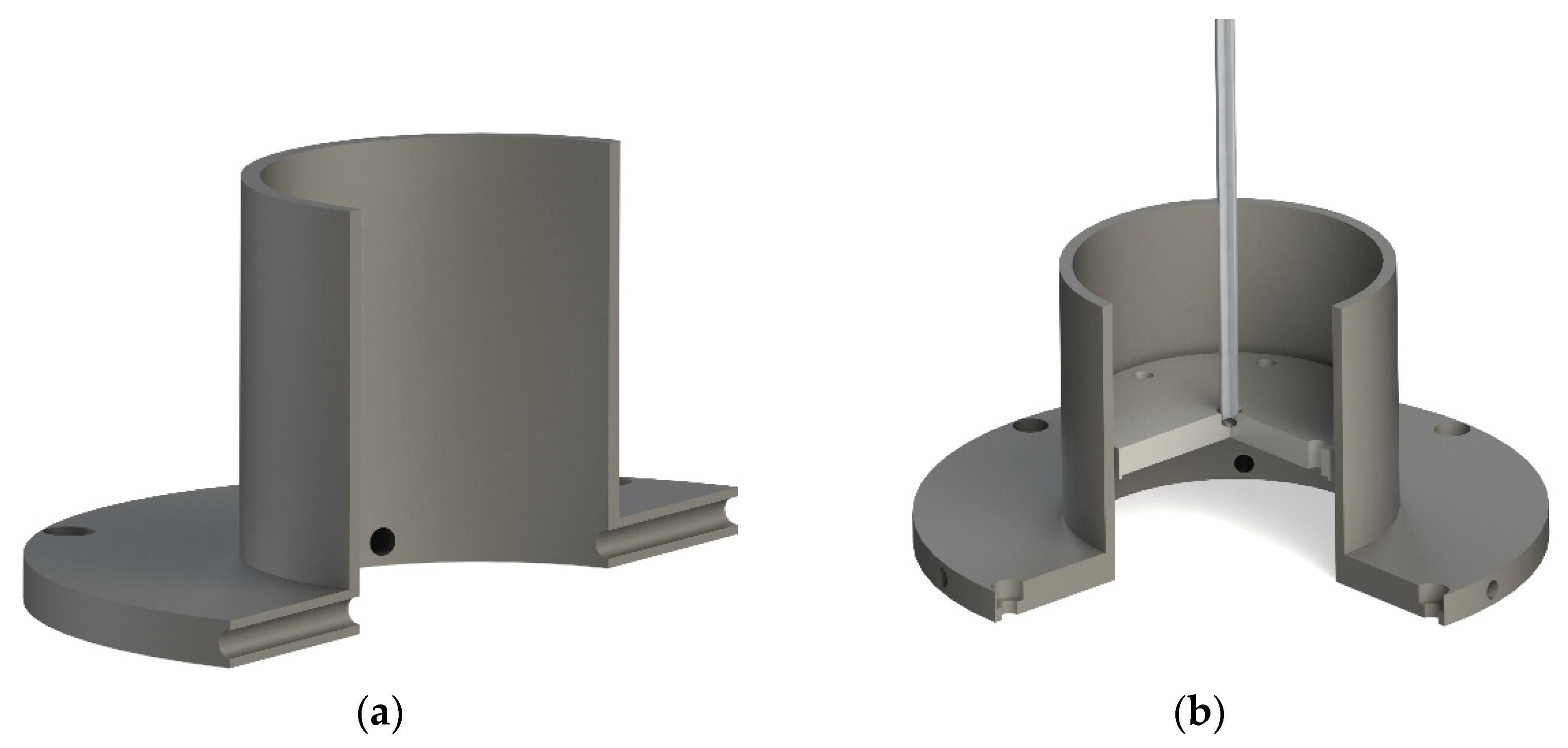
To achieve the goal of a replacement of the standard ground shield, the intended design of the new configuration must meet the requirements of the sputtering process: (1) provide a low outgassing rate, which will lead to the proper vacuum level and (2) give the access for free gas circulation to sustain the working pressure inside the close volume. To reach such requirements, it was planned to create an additional six tunnels (Ø 4 mm), indicated in
Figure 1a, in the base plate of the recovering shield, perpendicularly to the shield wall. The diameter of the cylinder was chosen according to the target size, which was, in our case, 2 inches. The length of the cylinder was chosen based upon the requirement that the deposition must occur as close as possible to the sputtering target, as presented in
Figure 1b. Possibly, such a decision would lead to some known difficulties with mechanical stresses induced on the film, thus reducing the possible sample holder size. However, from the material-saving point of view, it may help to prove a better target material utilization, thus improving the material recovery stage.
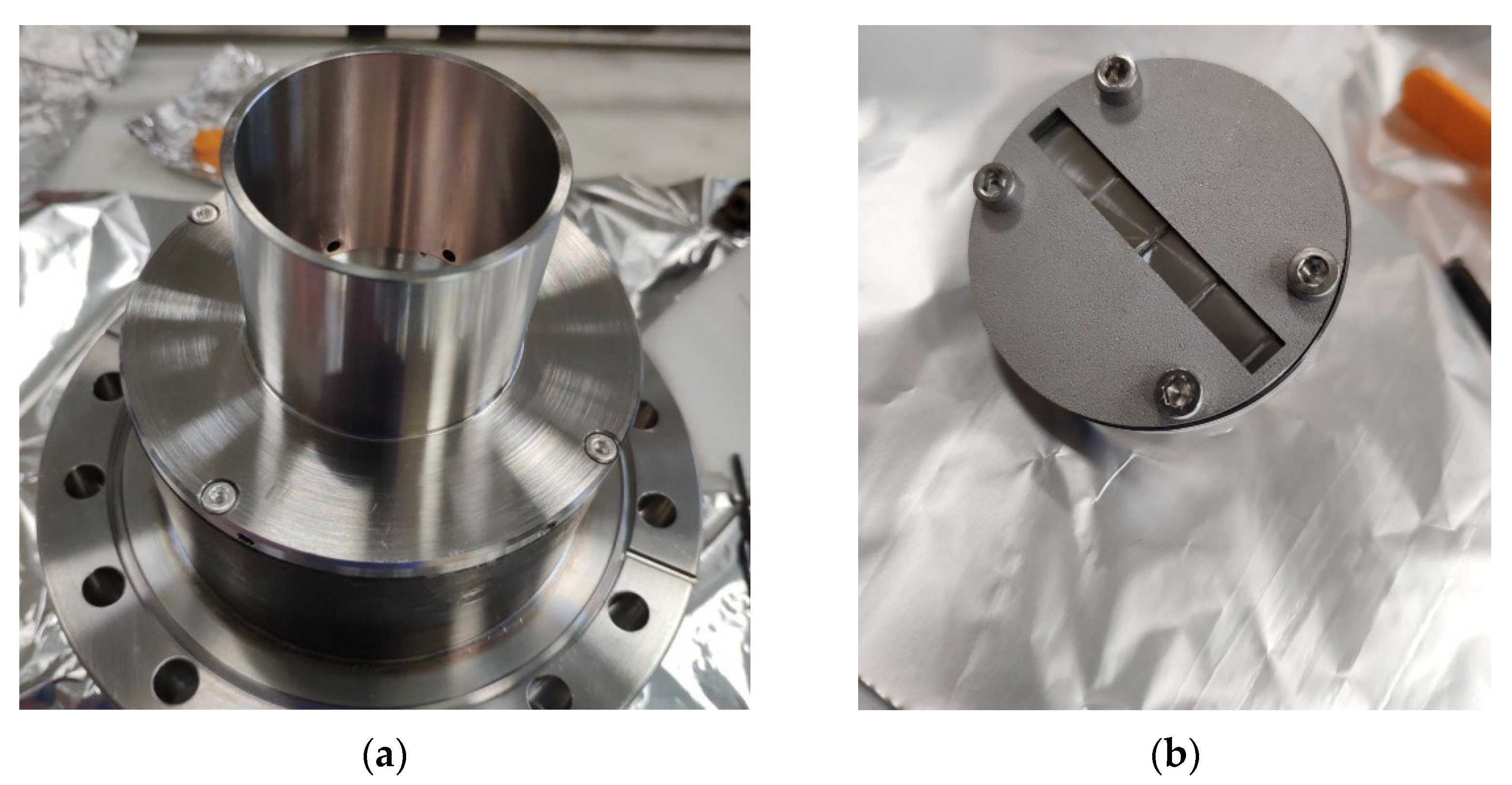
The recovering shield, shown in
Figure 2a, is made of stainless steel (AISI 316). The shield construction is a combination of a flat plate (repeating the function of a standard ground shield) and a cylinder (now made of SS but with the possibility to realize it in insulating material, such as SiO
2 or Al
2O
3 for special applications), as a collector for the sputtered material, usually deposited on the vacuum chamber walls.
The sample holder (SH) was designed for the assembling of four quartz samples (10 × 10 mm). The SH assembly, shown in
Figure 2b, consists of a stainless steel (AISI 316) base and top discs, four screws, nuts and rod with a proper length, all designed in SS. The effective surface left free for the SH is just 5%.
All mechanical parts were properly cleaned by applying the following procedures: ultrasound bath (1) with deionized water, with the addition of 5 mL of Rodaclean® (NGL Cleaning Technology SA, Nyon, Switzerland) soap for 20 min at 40 °C; (2) ultrasound bath with deionized water during 20 min at 40 °C; (3) rinsing with ethanol 96%; and (4) packaging in aluminum foil before assembling into the system. The cleaning process of the quartz samples follows the same protocol, except for the storage in ethanol in a plastic box. Just before the assembling of quartz samples to the SH, they were dried with N2 gas (oil-free system).
As for the target material, Cu (99.99% purity) was used. Such targets were prepared by the LNL mechanical workshop. The cleaning procedure followed for Cu targets has been the same used for the standard cleaning protocol adopted, although with a different detergent agent, the GP 17.40 SUP soap (NGL Cleaning Technology SA, Nyon, Switzerland).
The sputtering process was held in the stainless steel cylindrical vacuum chamber with the volume 12.3 dm3. Depositions were carried out by both DC magnetron and diode sputtering (DS) techniques. The base vacuum level was created by a primary and turbo molecular pump (the Edwards nXDS6i of 100 L/min and Pfeiffer turbo molecular pump of 60 L/s, respectively) with a base pressure always lower than 5 × 10⁻⁴ Pa without any additional baking procedure.
The duration of the MS process deposition was set at 390 min, with a sputtering current of 1 A. For the DS deposition, the time of the process was 630 min with the constant current of 0.1 A. The working pressure of the processes was kept at 0.78 and 34 Pa, respectively, while the distance between the sample holder and the target was fixed at 2 cm. As the sputtering process gas, standard ultrapure Ar (99.9999% purity) was used.
After the MS treatment, weight measurements were performed with electronic precision balances (Mettler Toledo group, EL303, accuracy 0.001 g). The growing behavior and thickness of the films achieved by both depositions were accurately investigated by scanning electron microscopy (FEI-formerly Philips, OR, USA Scanning Electron Microscope SEM XL-30).
3. Results
3.1. Material Distribution and Recovering
The first two depositions were carried out at the distance of 4.5 cm between the target and the SH in the top-down [
13] position. In such a configuration, some amount of Cu material was able to escape and was deposited on the walls of the vacuum chamber. In order to overcome such an issue, in the next experiments performed, the working distance was reduced to 2 cm. As a result, no visible Cu deposits were discovered on the chamber walls. All calculations were carried out on the basis of the result of the deposition made with the distance of 2 cm.
To continue with the weight-loss analysis, it was decided to weigh two main elements of magnetron: the central ring with its four screws and the recovering shield with its four screws. In each experiment, a new Cu target was used and weighted just before the assembling in the magnetron. In the calculation, the weight of the SH was considered as total weight of stick, base of the SH, cap of the SH, four screws with the nuts and four quartz samples.
The choice of the sputtering deposition parameters was based upon the past research experience with copper deposition. Since the deposit quality was not a priority for this study, there were no additional stress tests to carry out. In the case of the DS process, the working pressure was chosen with the aim to work below 1 kV voltage. To achieve a desirable working pressure, the vacuum pumping frequency of the turbomolecular pump was decreased manually to 375 Hz, compared to 700 Hz for the stand-by regime in the MS deposition. The parameters of both deposition processes are shown in
Table 1. All depositions were done in steps of 2–2.5 h.
After the MS deposition, the target erosion depth was measured by a height measuring device (Digimar 816 CL) to evaluate the residual thickness. In the thinner part of the target, it was reduced from 5 to 0.78 mm.
The weight of the sputtering target was evaluated before and after the deposition. The results shown in
Table 2 point out that, in the case of the MS process, only 23,882 g out of 88,811 g of the target source mass, which corresponds to 26.9%, was used during the deposition process. The rest of the target material requires future recovering. According to calculation, only 9280 g was deposited on the sample holder, while 13,441 g was collected on the recovering shield.
The target erosion depth after the DS process was not evaluated. In the ideal case, with the continued erosion for more than 20 days, the estimated usage of the target of the DS process would be 68.7%. Practically, only 1299 g of the target material was sputtered from the target, and only 21.6% has been trapped at the sample holder.
According to the calculation, the MS seems more efficient than the DS, except for the target mass usage. In the case of the recovering shield utilization, the obtained losses were less than 5%.
3.2. Evaluation of Deposited Layer
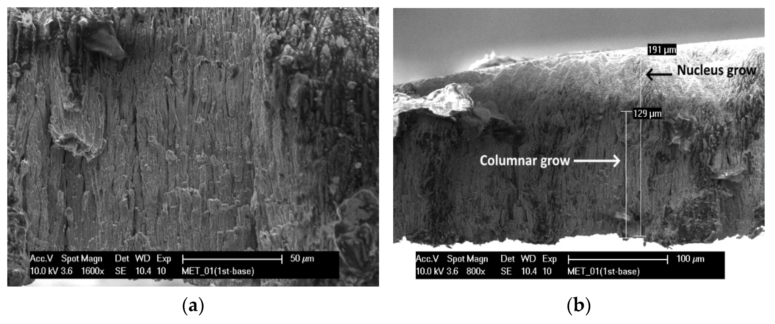
The deposition performed by the MS technique at the working distance of 4.5 cm, reached 200 µm of thickness. Without any additional heating and optimization of the parameters, the layer deposited turned out dense and without any visible defects. The low adherence of the coating with the quartz substrate gave us the possibility for a complete delamination of the relatively thick layer of Cu. Thus, it was possible to conduct a cross-section analysis of the first MS deposition, which showed a difference in the layer deposition growth. As can be seen in
Figure 3, the structure of the deposition changes from the columnar to nucleation type of growth after 100–120 µm.
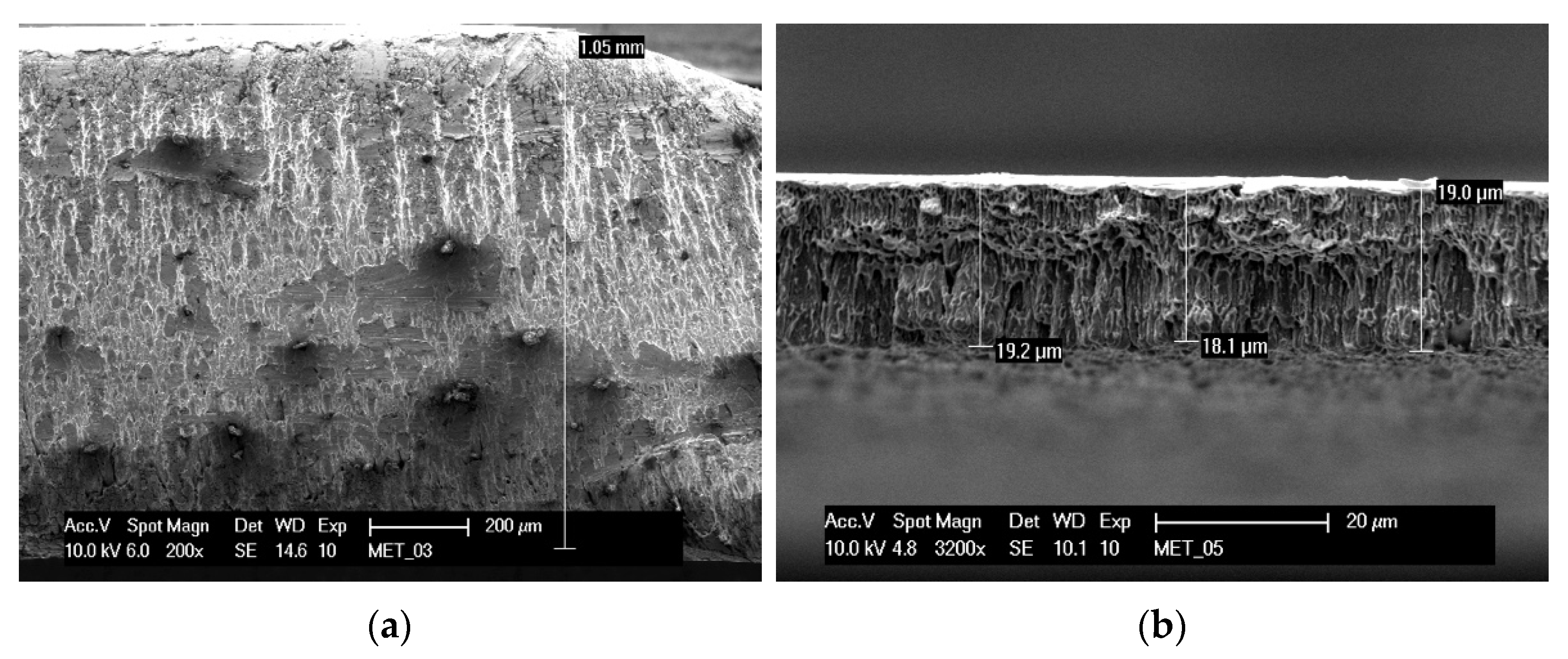
However, the selection of a closer distance between the source and the SH improved the deposition rate by a factor of 5. The thickness of the deposition achieved during the second magnetron sputtering process (see
Figure 4a) was ultra-thick, around 960 µm–1 mm.
The SEM micrographs of DS deposition, shown in
Figure 4b, let us see a more defined columnar structure through the thickness. The deposition rate in this case was 0.3 µm/min.
4. Discussion
The recovering shield was primarily designed just as a ground shield, able to reproduce the vacuum chamber’s wall and give a possibility for a proper material dissipation evaluation. During the R&D work, it was also proposed that the material collected on the recovering shield may be dissolved chemically or electrochemically, depending on its type. A possible upgrade of the shield may include the introduction of a glass cylinder to help with the deposit pilling or dissolution. The removed coating can be used to study the growing behavior and evaluate the contamination present in the film; meanwhile, the produced CSTs are stored in the vacuum protection bags. Any destroying analysis can be applied for such deposits. Theoretically, in case of a proper adjustment of the construction, such deposits can be reused in the cylindrical shape as a magnetron target for the cylindrical magnetron [
18]. Further experiments will involve the work with other metals and investigation of their recovering from the shield.
Evaluating the two applied techniques, the MS deposition process has shown to be more energetic and efficient both from the material dissipation and deposition rate criteria. It could be explained by the nature of diode and magnetron discharge processes. The DC diode sputtering can be realized only in high gas pressure (more than 1 Pa), which creates a great number of collisions where the electrons lose their energy. In the case of the MS, the closed magnetic path near the target leads to the creation of a high flux of electrons, giving as a result, a high-density plasma. Together with lower operating pressure, this gives the possibility to ions to be accelerated from plasma to the cathode without the loss of energy due to collision processes [
19].
On the other hand, the main drawback of the MS, the target usage limitation, remains. Due to the specific erosion shape, only 27% of the target material mass may indeed be used from one target and even less will be deposited on the dedicated substrate. The remaining 73% of it could be used to produce a new target and it requires additional operating time.
In the case of the DS deposition, this problem is completely avoided. The target material is uniformly eroded over the whole target surface, thus allowing for a longer target material usage. From this point of view, the DS appears to be quite a favorable technique. Moreover, the situation changes if we compare other parameters, such as the material losses, the amount of material deposited on the sample and the significant deposition rate drops. To deposit comparable thickness of the MS process (~900 µm in our case), more than a 20-day-long deposition time would be required. In such a way, the production line and the related cost behind each CST manufacturing aimed at radioisotope production may thus be unaffordable. Moreover, the material losses in the DS process are higher compared to the MS. The protective shield collects more than 70% of the material sputtered in the vacuum chamber. Such a result clearly points out that the DS technique, without the usage of a recovering shield, may not be used for the expensive isotopically enriched material depositions, which, moreover, occur in almost all the cases.
However, it may provide us a clear idea about benefits of both sputtering methods, prospects of designed shield utilization and its possible optimization.
The deposition rate in the MS and DS processes is not influenced by the recovering shield utilization, which is confirmed by the deposition rate measurement in similar operating conditions.
Currently, it is not feasible to carry out studies about the possible influence of temperature against the process deposition rate. However, the analysis of the films so far produced and their comparison with the structure zone model [
20,
21] can give an idea about the process temperature during the deposition.
Studying the growing behavior presented in
Figure 3a, it is possible to see the well-defined columnar dense structure of the Cu crystals, which then changes to the larger and wider structure present in
Figure 3b. It may suggest that the deposition started to grow up inside the transition zone [
21] T/T
m = 0.2–0.4 (where T
m is a material’s melting temperature) and then reached Zone 2 with T/T
m > 0.4. It may be thus assumed that the deposition temperature during the MS process with the use of the recovering shield and a distance of 2 cm, started near 200 °C and rose to 400–600 °C. Changes in the working pressure, which are assumed to have occurred during the deposition in the limited volume of the recovering shield, do not play a significant role in the case of the high T/T
m [
20].
Evaluation of the growing structure of the Cu coating in the case of the DS deposition (see
Figure 4b) shows a homogeneous behavior. The crystal’s structure is like that presented in
Figure 3a and probably also corresponds to the transition zone with the T/T
m close to 0.2 and a temperature range of 200–300 °C.
To prove the assumption, future experiments with the proper temperature measuring system will be necessary, along with the evaluation of other kinds of metal depositions.
5. Conclusions
The material dissipation in the MS and DS deposition processes was evaluated by using a weight-loss analysis. The new protective shield designed and tested for this study has shown a possibility for a significant recovery of the target material during the sputtering processes, both in the MS and DS options. Utilization of a recovering shield can decrease the losses of the material from 70% down to 10%.
The MS was identified as a method of choice for radiopharmaceutical applications, despite its drawback concerning a special target erosion.
The possibility of a thick film (more than 100 µm) deposition devoted to a radiopharmaceutical application, specifically for CST production, was demonstrated in the work.
Author Contributions
Conceptualization, O.A., G.K. and C.P.; methodology and investigation, A.K. and O.A.; formal analysis, data curation, visualization and writing original draft, A.K.; validation, supervision, O.A., G.K., C.P. and J.E.; project administration, O.A., G.K. and J.E.; resources, G.K., C.P. and J.E.; funding acquisition, J.E.; writing—review and editing, O.A., G.K., J.E. and A.K. All authors have read and agreed to the published version of the manuscript.
Funding
This research was funded by CSN5 of the Istituto Nazionale di Fisica Nucleare, Italy for 2018–2022, in the framework of METRICS project. National responsible: J. Esposito.
Institutional Review Board Statement
Not applicable.
Informed Consent Statement
Not applicable.
Acknowledgments
Special thanks should be given to Oscar Azzolini, for his continued support during the experimental part and ideas-sharing sessions. We want to also acknowledge Juan Esposito for his work as a head of the research project.
Conflicts of Interest
The authors declare no conflict of interest.
References
- Baptista, A.; Silva, F.; Porteiro, J.; Míguez, J.; Pinto, G.; Fernandes, L. On the Physical Vapour Deposition (PVD): Evolution of Magnetron Sputtering Processes for Industrial Applications. Procedia Manuf. 2018, 17, 746–757. [Google Scholar] [CrossRef]
- Dallaeva, D.; Bilalov, B.; Gitikchiev, M.; Kardashova, G.; Safaraliev, G.; Tománek, P.; Škarvada, P.; Smith, S. Structural properties of Al2O3/AlN thin film prepared by magnetron sputtering of Al in HF-activated nitrogen plasma. Thin Solid Films 2012, 526, 92–96. [Google Scholar] [CrossRef]
- Baptista, A.; Silva, F.; Porteiro, J.; Míguez, J.; Pinto, G. Sputtering Physical Vapour Deposition (PVD) Coatings: A Critical Review on Process Improvement and Market Trend Demands. Coatings 2018, 8, 402. [Google Scholar] [CrossRef] [Green Version]
- Bräuer, G.; Szyszka, B.; Vergöhl, M.; Bandorf, R. Magnetron sputtering—Milestones of 30 years. Vacuum 2010, 84, 1354–1359. [Google Scholar] [CrossRef]
- PalDey, S.; Deevi, S. Single layer and multilayer wear resistant coatings of (Ti,Al)N: A review. Mater. Sci. Eng. A 2003, 342, 58–79. [Google Scholar] [CrossRef]
- Pederson, L.; Singh, P.; Zhou, X.-D. Application of vacuum deposition methods to solid oxide fuel cells. Vacuum 2006, 80, 1066–1083. [Google Scholar] [CrossRef]
- Szyszka, B.; Dewald, W.; Gurram, S.K.; Pflug, A.; Schulz, C.; Siemers, M.; Sittinger, V.; Ulrich, S. Recent developments in the field of transparent conductive oxide films for spectral selective coatings, electronics and photovoltaics. Curr. Appl. Phys. 2012, 12, S2–S11. [Google Scholar] [CrossRef]
- Yang, Y.; Wang, T.; Yao, T.; Li, G.; Sun, Y.; Cao, X.; Ma, L.; Peng, S. Preparation of a novel TiN/TiNxOy/SiO2 composite ceramic films on aluminum substrate as a solar selective absorber by magnetron sputtering. J. Alloys Compd. 2020, 815, 152209. [Google Scholar] [CrossRef]
- Braccini, S.; Belver-Aguilar, C.; Carzaniga, T.; Dellepiane, G.; Haeffner, P.; Scampoli, P. Novel Irradiation Methods for Theranostic Radioisotope Production With Solid Targets at the Bern Medical Cyclotron. In Proceedings of the 22nd International Conference on Cyclotrons and their Applications, Cape Town, South Africa, 23–27 September 2019; p. 5. [Google Scholar]
- Kasbollah, A.; Eu, P.; Cowell, S.; Deb, P. Review on Production of 89Zr in a Medical Cyclotron for PET Radiopharmaceuticals. J. Nucl. Med. Technol. 2013, 41, 35–41. [Google Scholar] [CrossRef] [PubMed]
- Rajec, P.; Csiba, V.; Leporis, M.; Stefecka, M.; Pataky, E.L.; Reich, M.; Ometáková, J. Preparation and characterization of nickel targets for cyclotron production of 64Cu. J. Radioanal. Nucl. Chem. 2010, 286, 665–670. [Google Scholar] [CrossRef]
- Nelson, B.J.; Wilson, J.; Richter, S.; Duke, M.J.M.; Wuest, M.; Wuest, F. Taking cyclotron 68Ga production to the next level: Expeditious solid target production of 68Ga for preparation of radiotracers. Nucl. Med. Biol. 2020, 80–81, 24–31. [Google Scholar] [CrossRef] [PubMed]
- Skliarova, H.; Cisternino, S.; Cicoria, G.; Marengo, M.; Palmieri, V. Innovative Target for Production of Technetium-99m by Biomedical Cyclotron. Molecules 2018, 24, 25. [Google Scholar] [CrossRef] [PubMed] [Green Version]
- Skliarova, H.; Cisternino, S.; Cicoria, G.; Marengo, M.; Cazzola, E.; Gorgoni, G.; Palmieri, V. Medical Cyclotron Solid Target Preparation by Ultrathick Film Magnetron Sputtering Deposition. Instruments 2019, 3, 21. [Google Scholar] [CrossRef] [Green Version]
- Skliarova, H.; Cisternino, S.; Cicoria, G.; Cazzola, E.; Gorgoni, G.; Marengo, M.; Esposito, J. Cyclotron solid targets preparation for medical radionuclides production in the framework of LARAMED project. J. Phys. Conf. Ser. 2020, 1548, 012022. [Google Scholar] [CrossRef]
- Queern, S.L.; Aweda, T.A.; Massicano, A.V.F.; Clanton, N.A.; El Sayed, R.; Sader, J.A.; Zyuzin, A.; Lapi, S.E. Production of Zr-89 using sputtered yttrium coin targets. Nucl. Med. Biol. 2017, 50, 11–16. [Google Scholar] [CrossRef] [PubMed]
- Esposito, J.; Bettoni, D.; Boschi, A.; Calderolla, M.; Cisternino, S.; Fiorentini, G.; Keppel, G.; Martini, P.; Maggiore, M.; Mou, L.; et al. LARAMED: A Laboratory for Radioisotopes of Medical Interest. Molecules 2018, 24, 20. [Google Scholar] [CrossRef] [PubMed] [Green Version]
- Thornton, J.A. Magnetron sputtering: Basic physics and application to cylindrical magnetrons. J. Vac. Sci. Technol. 1978, 15, 171–177. [Google Scholar] [CrossRef]
- Mattox, D.M. Handbook of Physical Vapor Deposition (PVD) Processing; Elsevier: Amsterdam, The Netherlands, 2010. [Google Scholar]
- Thornton, J.A. Influence of apparatus geometry and deposition conditions on the structure and topography of thick sputtered coatings. J. Vac. Sci. Technol. 1974, 11, 666–670. [Google Scholar] [CrossRef]
- Thornton, J.A. High Rate Thick Film Growth. Annu. Rev. Mater. Res. 1977, 7, 239–260. [Google Scholar] [CrossRef]
| Publisher’s Note: MDPI stays neutral with regard to jurisdictional claims in published maps and institutional affiliations. |
© 2021 by the authors. Licensee MDPI, Basel, Switzerland. This article is an open access article distributed under the terms and conditions of the Creative Commons Attribution (CC BY) license (https://creativecommons.org/licenses/by/4.0/).


