Article

Numerical Study on the Effect of Enhanced Buffer Materials in a High-Level Radioactive Waste Repository

1
Deep Subsurface Research Center, Korea Institute of Geoscience and Mineral Resources (KIGAM), Daejeon 34132, Korea
2
Radioactive Waste Disposal Research Division, Korea Atomic Energy Research Institute (KAERI), Daejeon 34057, Korea
*
Author to whom correspondence should be addressed.
Appl. Sci. 2021, 11(18), 8733; https://doi.org/10.3390/app11188733
Submission received: 1 September 2021 / Revised: 16 September 2021 / Accepted: 16 September 2021 / Published: 18 September 2021
(This article belongs to the Special Issue Investigation of Thermal Properties in Soil and Rock)

Abstract

:
In deep geological disposal system designs, it is important to minimize the installation area for cost effectiveness while satisfying the thermal requirements of the systems. An effective method to reduce the installation area for the systems is to employ an enhanced buffer material, as this can decrease the spacing between the disposal tunnels and deposition holes. Therefore, this study aims to evaluate the effect of an enhanced buffer material on the thermal behavior of the systems and their spacing. First, the discrete element method (DEM) was adopted to validate the thermal conductivity of the enhanced buffer material used, which was a mixture of bentonite and graphite. Then, a 3D finite element method (FEM) was conducted to analyze the proper disposal tunnel and hole spacing considering three cases with thermal conductivities values of the buffer as 0.8 W/(m K), 1.0 W/(m K), and 1.2 W/(m K). The results showed that the disposal tunnel and hole spacing could be reduced to 30 m and 6 m, respectively, when the temperature of the buffer surface facing the canister was 100 °C with a thermal conductivity value of approximately 1.2 W/(m K) or if more than 3% of graphite is added.

1. Introduction

It is crucial to dispose of high-level radioactive waste (HLW) safely to sustain nuclear power generation and protect the environment. One of the most reliable methods for permanently isolating HLWs from human society is to reposit them in a deep geological disposal system combined with the concept of an engineered barrier system (EBS), which is composed of canisters containing the used fuels, buffers wrapping the canisters and filling the repository holes, backfills for disposal tunnels, and near-field rocks.
In the design of the EBS, it is critical to consider the thermal behavior of the system because the peak temperature of the buffer should remain below 100 °C during the system’s operation. This is to prevent the deterioration of the safety performance of the buffer and corrosion in the disposal container [1,2,3,4]. To ensure the advantageous conditions of the system for the thermal requirement at the design stage, an enhanced buffer with high thermal conductivity, compared to the conventional buffer, is utilized to decrease the peak temperature during the operation. Thus, many studies have been conducted to improve the thermal conductivity of the buffer for the development of enhanced buffers [5,6,7]. Bentonite has been considered the primary material for the buffer because it swells by absorbing water and has a low hydraulic conductivity; therefore, it maintains the position of the canister and prohibits water from contacting the nuclide in the canister. The thermal conductivity of pure bentonite is in the range of 0.2–1.5 W/(m∙K) with respect to the dry density, degree of saturation, and temperature [8,9].
A simple technique to develop an enhanced buffer is to change the composition of the material by increasing the sand content in the components. The thermal conductivity of the buffer increases with the addition of silica sand because of its relatively large particle size and high thermal conductivity compared to bentonite [10,11,12,13,14]. As the sand content of the buffer increases, the thermal conductivity increases until it reaches the limitation value. Then, it shows a tendency to decrease as the sand content also increases [15,16]. Graphite can be added to the buffer material as another method to enhance the buffer. Unlike sand, only 3% graphite in bentonite can increase its thermal conductivity by more than 1 W/(m∙K), which is 20% higher than the thermal conductivity of unmixed bentonite [17].
Furthermore, the spacing of disposal tunnels and deposition holes within the system has a significant effect on the peak temperature of the buffer (Figure 1). If the spacing is not sufficient, the peak temperature of the buffer increases owing to the thermal interference effect of the canister, which has a negative effect on satisfying the thermal requirement of the buffer. Therefore, the spacing should be designed to meet the thermal requirements. This has a significant correlation with the thermal conductivity of the buffer. Therefore, the most important advantage of using an enhanced buffer material is the improvement in cost efficiency. If an enhanced buffer material is used, the peak temperature of the buffer is lowered. Thus, the spacing can be reduced to fit the range that satisfies the thermal requirement, leading to a reduction in the construction cost of the entire HLW repository. Thus, it is important to investigate the effect of the enhanced buffer on the installation spacing regarding the disposal tunnels and deposition holes in the design process of an HLW repository. Nevertheless, there has been a lack of research on the methods to reduce the spacing between the disposal tunnels and deposition holes by adopting an enhanced buffer. In addition, investigation is required to determine whether the thermal requirement is satisfied when the spacing is reduced.
Therefore, a numerical study was conducted based on the 3D finite element method (FEM) with regard to the enhanced buffer material and the spacing between the disposal tunnels and deposition holes. For porous solids and especially powdery systems, it is very difficult to obtain a reliable value. However, various authors within the field of composite materials have developed procedures to efficiently determine effective thermal conductivity from the intrinsic conductivity data of the different components, volume fraction, etc. Thus, for this numerical study, the experimental thermal conductivity value of the bentonite mixture with 3% graphite was verified through a discrete element method (DEM). Although there is a method to use the model to calculate a thermal conductivity of complex material including a conductor such as metal [18,19,20], the DEM numerical analysis method was used consider the 3D condition and the soil structure.

2. Preparation for the Numerical Analysis

For the enhanced buffer material, the experimental results obtained by Lee et al. (2013) [17] with regard to the thermal conductivity of bentonite mixed with 3% graphite were applied to the HLW disposal repository. The specific heat capacities of bentonite and graphite for the numerical analysis were obtained from the studies of Yoon et al. (2019) [21] and Picard et al. (2007) [22], respectively. The thermal conductivity of bentonite mixed with 3% graphite was analyzed through a discrete element method (DEM) numerical analysis using the specific heat capacities of bentonite and graphite from the references [21,22]. This procedure was to check whether the specific heat capacity values from the references could be used as the material properties of bentonite and graphite used in the experiment of the reference [17] for the FEM numerical simulation.

2.1. Input Parameters for DEM

The particles of bentonite and graphite were assumed to be spherical. Both the particles were in a powdered form; therefore, when viewed with the naked eye, they were both determined to be 1 mm in diameter. The thermal conductivities of bentonite and graphite were 0.5 W/(m∙K) under dry conditions when their dry densities were 1.67 g/cm3 and 130 W/(m∙K), respectively [17]. The specific heat capacities of bentonite and graphite were 696 J/(kg·K) (considering the specific heat capacity model and its determination coefficient in Yoon et al. (2019) [21]) and 700 J/(kg·K) [22], respectively.
The bentonite and graphite particles were randomly filled in a ratio of 97:3 in a cuboid geometry with 5 mm width, 5 mm length, and 10 mm height. The total number of particles was 244 (237 bentonite particles and 7 graphite particles). Accumulated particles in the cuboid geometry were pressed downward by lowering the lid plate geometry ≈1.5 mm so that the dry density of the particles was 1.67 g/cm3 (Figure 2). The porosity of the packed particles was 39.88%. Then, a temperature of 373.15 K was applied to the lid plate geometry. The heat of the lid plate geometry was transferred to the particles touching the plate, which resulted in heat conduction through the particles. The thermal conductivity of mixed particles was calculated based on the temperature difference between the particles heated directly because of contact with the lid plate and the particles at the bottom heated because of the heat flux during the heat conduction, according to the following equation:
λ = q × L T 2 T 1
where λ is the thermal conductivity, q is the heat flux, L is the distance between the particles under the hot particles touching the hot plate directly and the particles on the bottom, T2 is the temperature of the particles under the particles touching the hot plate, and T1 is the temperature of the particles on the bottom plate.

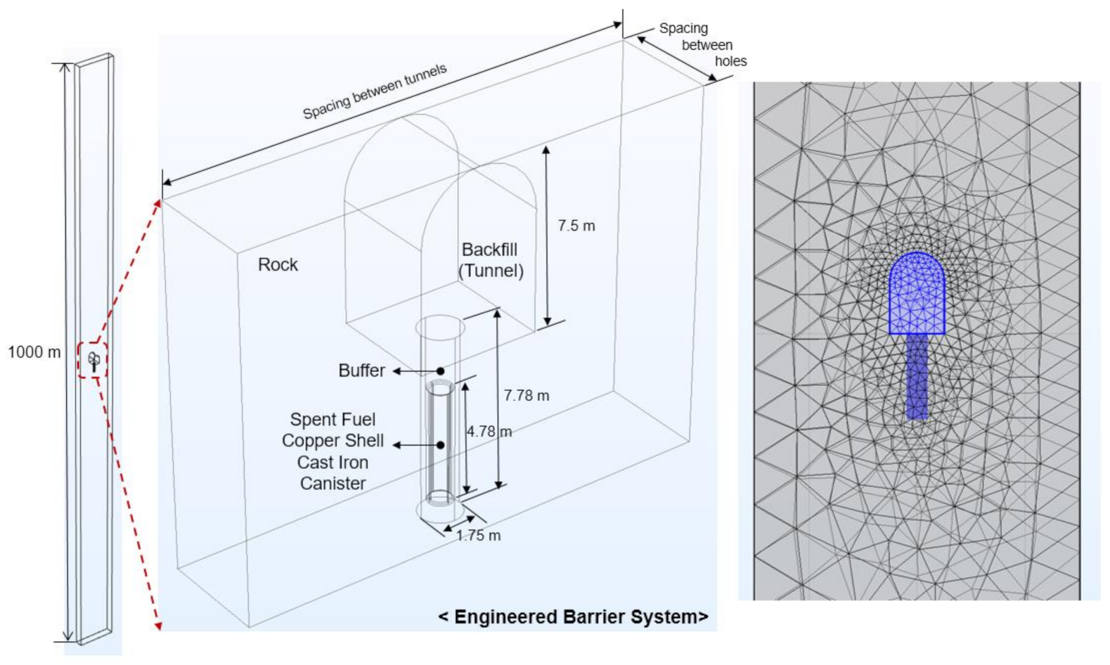
2.2. Construction of the Numerical Model

A numerical study was conducted to evaluate the effect of enhanced buffer materials on the arrangement of disposal tunnels and deposition holes. This study employed COMSOL Multiphysics 5.5 [23], which is a commercial program based on the theory of continuum mechanics and FEM, to investigate the thermal behavior of a deep geological system. The program has a built-in module for solving the heat transfer mechanisms, which occur during the operation of the disposal system.
In thermal analysis, heat conduction in the entire disposal system component was considered while implementing the heat transfer module in COMSOL Multiphysics. The governing equation for the module is expressed as follows [24]:
λ i ( 2 T x 2 + 2 T y 2 + 2 T z 2 ) + ρ i c i T t + q i = 0 ( i = x , y , z )
where T is the temperature of the porous medium as a dependent variable, λ is the thermal conductivity of the medium, ρ is the density, c is the specific heat capacity, and qi denotes the internal heat generation.
The numerical model was established based on the design concept of the improved Korean Reference Disposal System (KRS+) proposed to dispose of the PWR spent nuclear fuel generated in Korea. This is also called the Regular-Spent Nuclear Fuel (R-SNF) disposal system, which has a 40 m distance between the disposal tunnels and a distance of 7.5 m between the deposition holes to satisfy the upper temperature limit of 100 °C at the buffer surface facing a canister [25]. A 3D finite element model, including the components of the disposal system (backfill, buffer, canister, and rock), was constructed assuming that the disposal system was located at a depth of 500 m. Figure 3 shows the geometry and domain size of the numerical model, and Table 1 presents the input data for the properties of each component of the system. The concept of a DEM described in Section 2.1 was used to validate the input data for the buffer.
In the R-SNF disposal system, the used fuel is stored in a canister after a temporary storage period of 45 years in a temporary storage tank [25]. The decay heat from the spent nuclear fuel is used as the heat source for the canister in the simulation. The heat output from a canister of the Korean reference used fuels can be calculated using the following equation [25,26]:
Y = y 0 + A 1 × exp t × x 0 t 1 + A 2 × exp t x 0 t 2 + A 3 × exp t x 0 t 3
where Y is the decay heat (W) varying with the elapsed time from the reactor per unit weight (1 tU) of the reference PWR used fuels, and t is the time released from the reactor. Other coefficients, including x0, y0, A1, A2, A3, t1, t2, and t3, are constants, and their values are listed in Table 2.
A symmetry condition was chosen for the side surfaces as the boundary condition for the model. For the entire domain, a thermal gradient of 3 °C/100 m and a ground surface temperature of 10 °C were applied to the initial conditions to consider the temperature variations with respect to the underground depth. To consider the accuracy and efficiency of the analysis simultaneously, a fine mesh was formed in the canister and buffer near the heat source. The host rock far from the heat source was formed coarsely using a built-in function in COMSOL. Free tetrahedral-type 101,831 elements were formed with 10 nodes. The average mesh element quality, defined as the ratio of the element width and height, was 0.6403 for better convergence of the numerical analysis (Figure 3). The analysis time was 55 years, which is sufficient to investigate the peak temperature of the buffer, as the heat generated from the used fuel continuously decreases with time.
Nine cases were set up with respect to the thermal conductivity of the buffer and spacing between the disposal tunnels and deposition holes to investigate the effect of the enhanced buffer material on the arrangement of the system (Table 3). In Table 3, although the thermal conductivity value of 0.8 W/(m∙K) indicates the reference case, the thermal conductivity values of 1.0 W/(m∙K) and 1.2 W/(m∙K) represent the cases for enhanced thermal conductivity of the buffer.

3. Results: Numerical Analysis
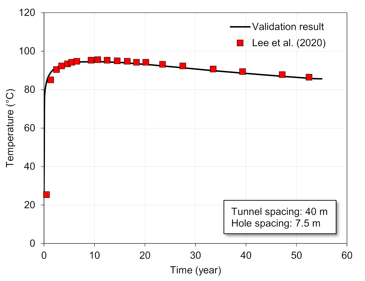
3.1. Validation

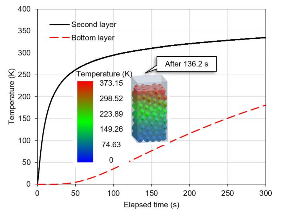
3.1.1. Input Parameters for DEM

The heat from the lid plate diffused through the particles (Figure 4). The thermal conductivity of the particles was 0.73 W/(m∙K), which agrees well with the experimental thermal conductivity value of 0.7 W/(m∙K) obtained using dry bentonite mixed with 3% graphite, following Lee et al. (2013) [17].

3.1.2. Thermal Analysis Using FEM

Prior to conducting a parametric study, the constructed numerical model was validated with the reference case with respect to the KRS+ disposal system presented by [27]. A numerical simulation employing the same boundary conditions and material properties as Lee et al. (2020) [27] resulted in a peak temperature value of the buffer surface facing the canister as 94.53 °C after 11.3 years. This result approximately corresponded to the analysis result of 95.3 °C after 11.0 years obtained by Lee et al. (2020) [27] (Figure 5).
Comparing the difference between these two models, the temperature of the buffer shows an average relative error of 1.04% during the entire period, and there is a relative error of 0.81% when the buffer reaches a peak temperature. In addition, the significance probability (p-value) between the two models was 0.648, which implies that there was no statistical significance [28]. Thus, it can be concluded that the constructed numerical model can accurately estimate the peak temperature of the buffer, and its results match well with the reference case.

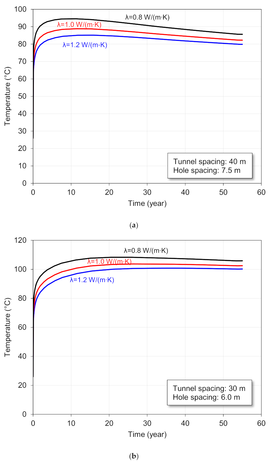
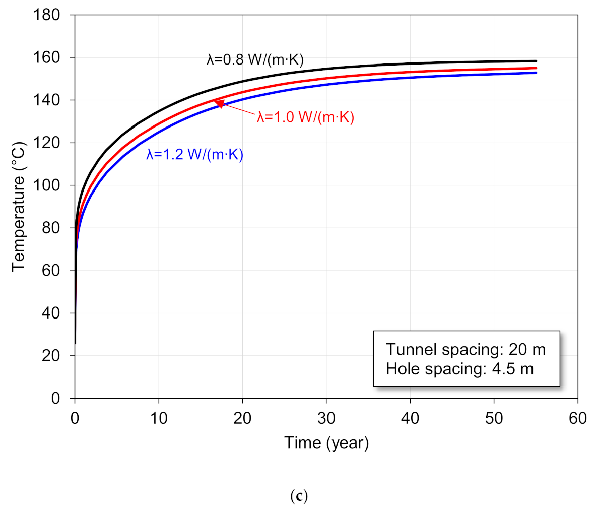
3.2. Parametric Study

Table 4 shows the numerical results for all the cases, and Figure 6 presents the temperature distributions of the EBS for the representative cases.
In case 1, the peak temperatures of the buffer at thermal conductivity values of 1.0 W/(m∙K) and 1.2 W/(m∙K) were 88.85 °C at 11.5 years and 85.15 °C at 15.7 years, respectively (Figure 7a). While there was no significant difference in the peak temperature values with respect to the thermal conductivity values, the peak temperature of the buffer when the thermal conductivity was 1.0 W/(m∙K) decreased by 6% compared to that when the thermal conductivity was 0.8 W/(m∙K). In contrast, the time required to reach the peak temperature of the buffer at the thermal conductivity of 1.2 W/(m∙K) was at least 4 years longer than that when the thermal conductivity was 1.0 W/(m∙K).
For the different spacing case 2, the peak temperatures of the buffer at thermal conductivity values of 0.8 W/(m∙K), 1.0 W/(m∙K), and 1.2 W/(m∙K) were 108.28 °C after 20.4 years, 103.66 °C after 26.1 years, and 100.76 °C after 34.9 years, respectively (Figure 7b). In this case, because the peak temperature of the buffer exceeds 100 °C for all the three thermal conductivity values, the thermal conductivity of the buffer should be higher than 1.2 W/(m∙K) to satisfy the thermal requirements of the disposal system.
In case 3 (Figure 7c), the temperature of the buffer increased continuously without attaining peak temperature within 55 years for all the thermal conductivities, and the temperature of the buffer exceeded 100 °C within 2.7 years for all the three thermal conductivity values because of insufficient spacing to emit the generated heat.

4. Discussion

The thermal conductivity of the buffer should be at least 0.8 W/(m∙K) to maintain the peak temperature of the buffer at 100 °C in the R-SNF condition. To maintain the peak temperature of the buffer below 90 °C, the thermal conductivity of the buffer should be 1.0 W/(m∙K) or higher in the R-SNF condition. In addition, to delay the time to reach the peak temperature of the buffer compared to when the thermal conductivity of the buffer is 0.8 W/(m∙K) while keeping the buffer peak temperature below 90 °C, the time required to reach the peak temperature of the buffer can be delayed by at least one year when the thermal conductivity of the buffer is 1.2 W/(m∙K) or higher. If graphite is used as an additive to the buffer, the thermal conductivity can be increased up to 1 W/(m∙K) even if only 3% graphite is added to the buffer. Furthermore, when 3% graphite is added to the buffer and its dry unit weight is 1.75 g/cm3, the thermal conductivity of the buffer is in the range of 1.2–1.3 W/(m∙K) [17]. In addition, the thermal conductivity of bentonite increases with respect to increasing temperature until reaching the criteria temperature of the buffer, 100 °C [9,29,30]. Especially, the thermal conductivity of bentonite increases by ≈20% at the temperature from 80 to 90 °C compared to that at room temperature [30]. Initially, the buffer facing a canister can be in a dry state by the heat from the canister, so that the water content of the buffer facing the canister is reduced. Thus, a buffer made of pure bentonite makes it difficult to reduce the disposal tunnel and hole spacings because pure bentonite is dependent on the water content, and the thermal conductivity of the pure bentonite is not larger than 1.2 W/(m∙K) if its water content is less than 15% [30]. Therefore, the distance of the disposal tunnels can be reduced to at least 30 m but less than 40 m, whereas that of the disposal holes can be reduced to at least 6 m but less than 7.5 m based on the temperature of the buffer (100 °C) by adding 3% graphite to the bentonite for the buffer when considering a conservative design. The spacings between disposal tunnels and between disposal holes can be further reduced by using the enhanced buffer material comparing the spacings between disposal tunnels and between disposal holes in the reference of Lee et al. (2020) [27]. Thus, the addition of 3% graphite in the R-SNF condition is effective in heat conduction from the canister. If the spacings of the disposal tunnels and the holes are reduced, the number of candidate sites for an HLW repository can be increased by a broadened range of site selections. In addition, the construction cost and period of an HLW repository can be also reduced.

5. Conclusions

This study evaluated the effect of spacing of the disposal hole and tunnel on the thermal conductivity of the buffer material through FEM analysis. The main focuses and findings of this paper are as follows:
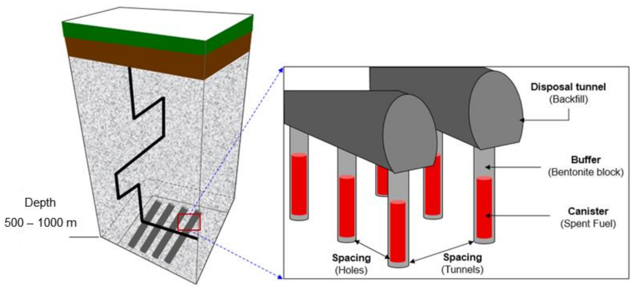
  • A high-performance buffer material with improved thermal conductivity was used in the study. We analyzed the reduction in the distance between the disposal tunnels and disposal holes from the R-SNF of KRS+ conditions in 3D using the FEM model.
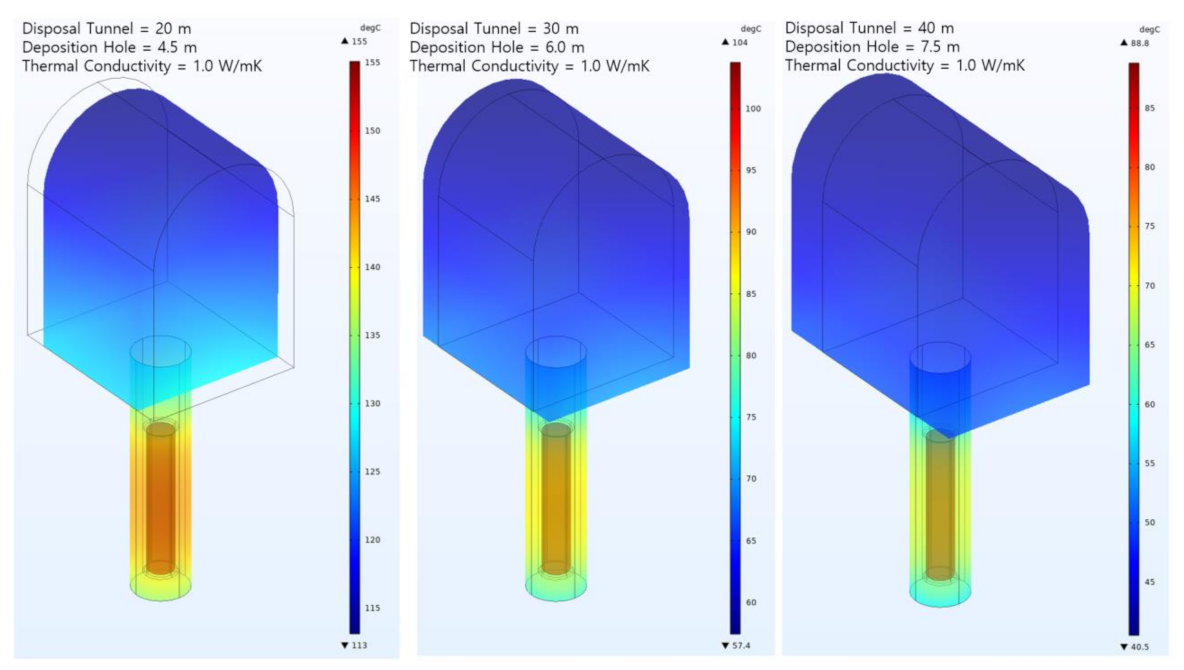
  • When a buffer material with a thermal conductivity of approximately 1.2 W/(m∙K) added with graphite was used, the R-SNF condition of 40 m distance between the disposal tunnels and 7.5 m distance between the disposal holes could be reduced to 30 m and 6 m between the disposal tunnels and between the disposal holes, respectively.
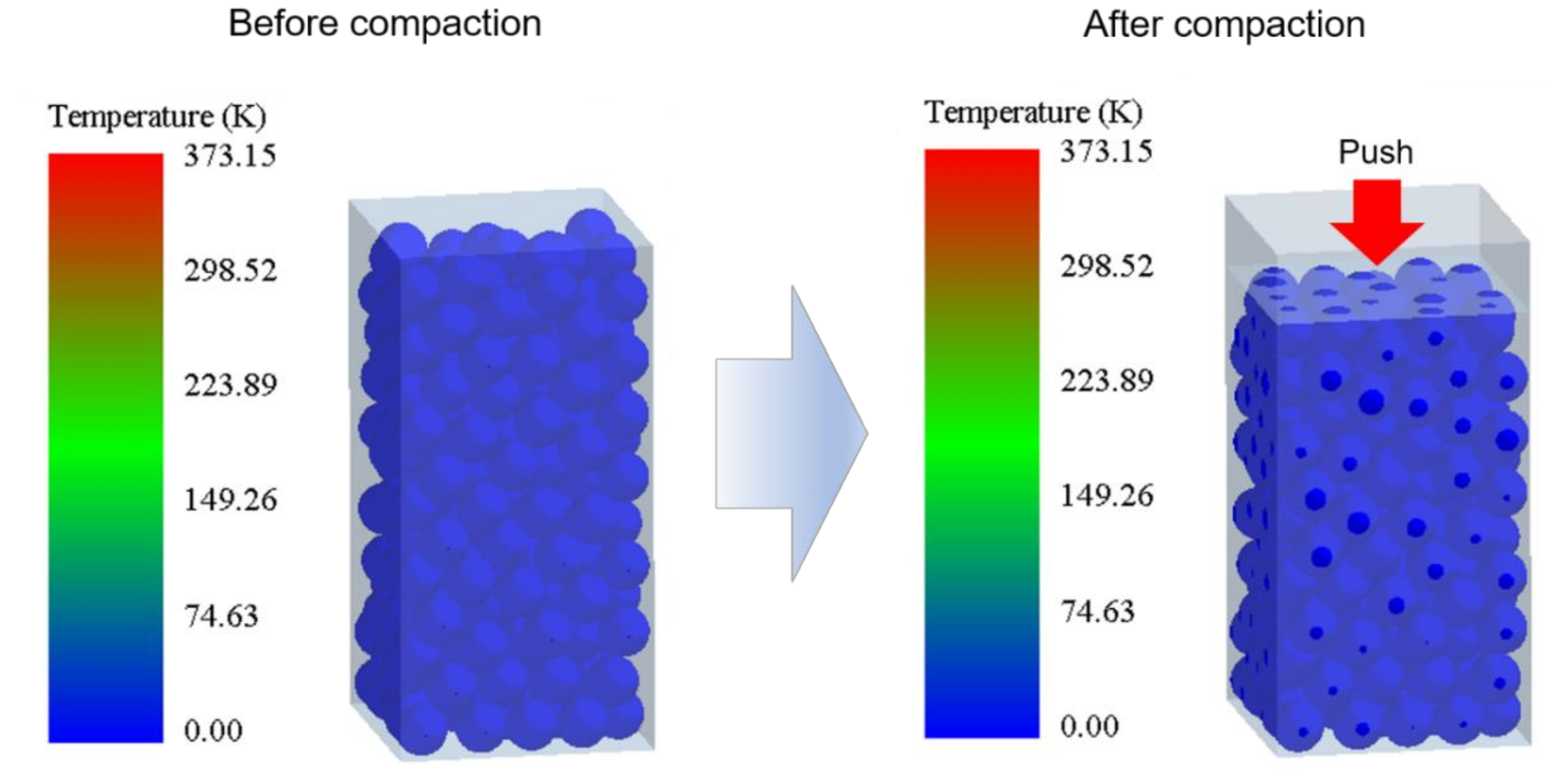
  • Additionally, the thermal conductivity test results conducted by Lee et al. (2013) [17] for bentonite mixed with graphite matched well with the results obtained from the DEM numerical analysis verification.
Although a validated 3D numerical model was applied in this study, it only considered the thermal analysis, indicating that the numerical results are likely to be affected by the fully coupled hydraulic–mechanical conditions in a deep geological repository. These coupled effects will be considered in future studies. In addition, in the future, enhanced buffer materials could meet all the requirements for high thermal–hydraulic–mechanical–chemical performance. Thus, considerations of all the processes must be developed. Nevertheless, this paper shows how much the spacings between disposal tunnels and between disposal holes can be narrowed when using enhanced buffer material with improved thermal conductivity well, and the results of this paper can be very useful when designing a high-level radioactive waste repository.

Author Contributions

Conceptualization, S.Y.; numerical analysis, M.-J.K., G.-J.L.; writing-original draft, G.-J.L.; writing-review and editing: M.-J.K., S.Y.; revision, G.-J.L. All authors have read and agreed to the published version of the manuscript.

Funding

This research was supported by the Nuclear Research and Development Program of the National Research Foundation of Korea (2021M2E3A2041351), and Basic Research Projects of the Korea Institute of Geoscience and Mineral Resources (KIGAM) funded by the Ministry of Science and ICT of Korea (GP 2020-010).

Institutional Review Board Statement

Not applicable.

Informed Consent Statement

Not applicable.

Conflicts of Interest

The authors declare no conflict of interest.

References

  1. Juvankoski, M.; Ikonen, K. Buffer Production Line 2012-Design, Production and Initial State of the Buffer; POSIVA Oy: Olkiluoto, Finland, 2012; pp. 73–74. [Google Scholar]
  2. Svensk Karnbranslehantering AB (SKB). Buffer and Backfill Process Report for the Safety Assessment SR-Can. In SKB Technical Report; SKB: Solna, Sweden, 2006; pp. 27–33. [Google Scholar]
  3. Simmons, G.R.; Baumgartner, P. The Disposal of Canada’s Nuclear Fuel Waste: Engineering for a Disposal Facility; Atomic Energy of Canada Ltd.: Chalk River, ON, Canada, 1994. [Google Scholar]
  4. Kim, M.J.; Lee, S.R.; Yoon, S.; Jeon, J.S.; Kim, M.S. Optimal Initial Condition of a Bentonite Buffer with Regard to Thermal Behavior in a High-Level Radioactive Waste Repository. Comput. Geotech. 2018, 104, 109–117. [Google Scholar] [CrossRef]
  5. Wang, Y.; Hadgu, T. Enhancement of Thermal Conductivity of Bentonite Buffer Materials with Copper Wires/Meshes for High-Level Radioactive Waste Disposal. Nucl. Technol. 2020, 206, 1584–1592. [Google Scholar] [CrossRef]
  6. Jobmann, M.; Buntebarth, G. Influence of Graphite and Quartz Addition on the Thermo-Physical Properties of Bentonite for Sealing Heating-Generating Radioactive Waste. Appl. Clay Sci. 2009, 44, 206–210. [Google Scholar] [CrossRef]
  7. Colin, L.; David, H.; Roger, T. Review of the Current Status of Work on Enhanced Bentonite Buffer Material; AMEC: London, UK, 2014. [Google Scholar]
  8. Knutsson, S. On the Thermal Conductivity and Thermal Diffusivity of Highly Compacted Bentonite. In SKB Technical Report; SKB: Solna, Sweden, 1983; pp. 72–83. [Google Scholar]
  9. Xu, Y.; Zeng, Z.; Lv, H. Temperature Dependence of Apparent Thermal Conductivity of Compacted Bentonites as Buffer Material for High-Level Radioactive Waste Repository. Appl. Clay Sci. 2019, 174, 10–14. [Google Scholar] [CrossRef]
  10. Japan Nuclear Cycle Development Institute. H12 Project to Establish the Scientific and Technical Basis for HLW Disposal in Japan, Supporting Report 2: Repository Design and Engineering Technology; Japan Nuclear Cycle Development Institute: Ibaraki, Japan, 2000. [Google Scholar]
  11. Sun, D.A.; Cui, H.; Sun, W. Swelling of Compacted Sand-Bentonite Mixtures. Appl. Clay Sci. 2009, 43, 485–492. [Google Scholar] [CrossRef]
  12. Sun, W.; Fang, L. Swelling Characteristics of Gaomiaozi Bentonite and Its Prediction. J. Rock Mech. Geotech. Eng. 2014, 6, 113–118. [Google Scholar] [CrossRef] [Green Version]
  13. Cui, S.L.; Zhang, H.Y.; Zhang, M. Swelling Characteristics of Compacted GMZ Bentonite-Sand Mixtures as a Buffer/Backfill Material in China. Eng. Geol. 2012, 141, 65–73. [Google Scholar] [CrossRef]
  14. Zhang, M.; Zhang, H.; Cui, S.; Jia, L.; Zhou, L.; Chen, H. Engineering Properties of GMZ Bentonite-Sand as Buffer/Backfilling Material for High-Level Waste Disposal. Eur. J. Environ. Civ. Eng. 2012, 16, 1216–1237. [Google Scholar] [CrossRef]
  15. Xu, L.; Ye, W.M.; Chen, B.; Chen, Y.G.; Cui, Y.J. Experimental Investigations on Thermo-Hydro-Mechanical Properties of Compacted GMZ01 Bentonite-Sand Mixture Using as Buffer Materials. Eng. Geol. 2016, 213, 46–54. [Google Scholar] [CrossRef]
  16. Zhuang, Y.C.; Xie, K.H.; Sun, Y.H. Experimental Study on Thermal Conductivity of Mixed Materials of Sand and Bentonite. Rock Soil Mech. 2005, 26, 261–264. [Google Scholar]
  17. Lee, M.; Choi, H.J.; Lee, J.W.; Lee, J.P. Improvement of the Thermal Conductivity of a Compact Bentonite Buffer; Korea Atomic Energy Research Institute: Daejeon, Korea, 2013. [Google Scholar]
  18. Molina, J.M.; Prieto, R.; Narciso, J.; Louis, E. The Effect of Porosity on the Thermal Conductivity of Al-12 wt.% Si/SiC Composites. Scr. Mater. 2009, 60, 582–585. [Google Scholar] [CrossRef]
  19. Prieto, R.; Molina, J.M.; Narciso, J.; Louis, E. Thermal Conductivity of Graphite Flakes-SiC Particles/Metal Composites. Compos. Part A Appl. Sci. Manuf. 2011, 42, 1970–1977. [Google Scholar] [CrossRef]
  20. Molina, J.M.; Rodríguez-Guerrero, A.; Louis, E.; Rodríguez-Reinoso, F.; Narciso, J. Porosity Effect on Thermal Properties of Al-12 Wt% Si/Graphite Composites. Materials 2017, 10, 177. [Google Scholar] [CrossRef] [PubMed] [Green Version]
  21. Yoon, S.; Jeon, J.S.; Kim, G.Y.; Seong, J.H.; Baik, M.H. Specific Heat Capacity Model for Compacted Bentonite Buffer Materials. Ann. Nucl. Energy 2019, 125, 18–25. [Google Scholar] [CrossRef]
  22. Picard, S.; Burns, D.T.; Roger, P. Determination of the Specific Heat Capacity of a Graphite Sample Using Absolute and Differential Methods. Metrologia 2007, 44, 294. [Google Scholar] [CrossRef]
  23. Comsol Inc. Comsol Multiphysics User’s Manual; Comsol Inc.: Burlington, MA, USA, 2019. [Google Scholar]
  24. Incropera, F.P.; Dewitt, D.P.; Bergman, T.L.; Lavine, A.S. Fundamentals of Heat and Mass Transfer, 6th ed.; John Willey Sons Inc.: New Jersey, NJ, USA, 2007. [Google Scholar]
  25. Lee, J.; Kim, I.; Choi, H.; Cho, D. An Improved Concept of Deep Geological Disposal System Considering Arising Characteristics of Spent Fuels from Domestic Nuclear Power Plants. J. Nucl. Fuel Cycle Waste Technol. 2019, 17, 405–418. [Google Scholar] [CrossRef]
  26. Choi, H.J.; Lee, J.Y.; Choi, J. Development of Geological Disposal Systems for Spent Fuels and High-Level Radioactive Wastes in Korea. Nucl. Eng. Technol. 2013, 45, 29–40. [Google Scholar] [CrossRef] [Green Version]
  27. Lee, J.; Kim, I.; Ju, H.; Choi, H.; Cho, D. Proposal of an Improved Concept Design for the Deep Geological Disposal System of Spent Nuclear Fuel in Korea. J. Nucl. Fuel Cycle Waste Technol. 2020, 18, 1–19. [Google Scholar] [CrossRef]
  28. Anthony, J. Probability and Statistics for Engineers and Scientists, 4th ed.; Thomson Brooks/Cole: Pacific Grove, CA, USA, 2012. [Google Scholar]
  29. Lee, J.O.; Choi, H.; Lee, J.Y. Thermal Conductivity of Compacted Bentonite as a Buffer Material for a High-Level Radioactive Waste Repository. Ann. Nucl. Energy 2016, 94, 848–855. [Google Scholar] [CrossRef]
  30. Yoon, S.; Kim, M.J.; Park, S.; Kim, G.Y. Thermal Conductivity Prediction Model for Compacted Bentonites Considering Temperature Variations. Nucl. Eng. Technol. 2021, 53, 3359–3366. [Google Scholar] [CrossRef]
Figure 1. Schematics of deep geological repository and spacing of disposal tunnels and deposition holes.
Applsci 11 08733 g001
Figure 2. Discrete element method (DEM) modelling for bentonite and graphite mixed particles with bulk dry density of 1.67 g/cm3.
Applsci 11 08733 g002
Figure 3. Geometry of 3D finite element model and generated mesh.
Applsci 11 08733 g003
Figure 4. Heat diffusion through the particles.
Applsci 11 08733 g004
Figure 5. Validation result compared to the reference result for temperature of the buffer based on the R-SNF condition.
Applsci 11 08733 g005
Figure 6. Representative numerical results for temperature distribution of the engineered barrier system according to the spacing.
Applsci 11 08733 g006
Figure 7. Temperature of buffer surface facing the canister with time according to the tunnel and hole spacing and thermal conductivity of the buffer: (a) tunnel and hole spacing are 40 and 7.5 m, respectively, (b) tunnel and hole spacing are 30 and 6.0 m, respectively, (c) tunnel and hole spacing are 20 and 4.5 m, respectively.
Applsci 11 08733 g007aApplsci 11 08733 g007b
Table 1. Thermal properties for the numerical model.
Density (kg/m3)Thermal Conductivity (W/(m∙K))Specific Heat Capacity (J/kgK)
Copper Shell8900386383
Cast Insert720052504
Backfill19700.81380
Rock227021190
Bentonite BufferParametric study
Table 2. Coefficient of regression equation for decay heat of PWR used fuels [27].
Itemsy0x0A1t1
Value297.95260.78053218.38282.9441
ItempsA2t2A3t3
Value10394.93851.09662036.430942.7499
Table 3. Case set up for parametric study.
CaseTunnel Spacing (m)Hole Spacing (m)Thermal Conductivity of Buffer (W/(m∙K))
1407.50.8
21.0
31.2
4306.00.8
51.0
61.2
7204.50.8
81.0
91.2
Table 4. Maximum temperature of the buffer surface facing the canister with conditions.
CasesThermal Conductivities (λ, W/(m∙K))
0.81.01.2
Tunnel spacing: 40 m Hole spacing: 7.5 mMax.temperature (T, °C)94.5388.8585.15
Time to reach max.T (years)11.311.515.7
Tunnel spacing: 30 m Hole spacing: 6.0 mMax.temperature (T, °C)108.28103.66100.76
Time to reach max.T (years)20.426.134.9
Tunnel spacing: 20 m Hole spacing: 4.5 mMax.temperature (T, °C)Divergence within 55 years
Time to reach max.T (years)
Publisher’s Note: MDPI stays neutral with regard to jurisdictional claims in published maps and institutional affiliations.

