Article

Investigation of 2DOF PID Controller for Physio-Therapeutic Application for Elbow Rehabilitation

1
Mechatronics Engineering, International Islamic University Malaysia, Kula Lumpur 43200, Malaysia
2
School of Engineering, RMIT University, Melbourne, VIC 3000, Australia
3
School of Industrial & System Engineering, University of Oklahoma, Norman, OK 73019, USA
4
School of Aerospace & Mechanical Engineering, University of Oklahoma, Norman, OK 73019, USA
5
School of Engineering, Deakin University, Geelong, VIC 3216, Australia
*
Authors to whom correspondence should be addressed.
Appl. Sci. 2021, 11(18), 8617; https://doi.org/10.3390/app11188617
Submission received: 25 August 2021 / Revised: 9 September 2021 / Accepted: 13 September 2021 / Published: 16 September 2021
(This article belongs to the Section Robotics and Automation)

Abstract

:
The aim of this work is to evaluate the output of a two-degree of freedom (DOF) proportional integral derivative (PID) controller for controlling elbow flexion and extension on an upper limb rehabilitation robot of an existing model. Since the usage of upper limb rehabilitation is increasing dramatically because of human impairment, 2DOF has been proposed in this work as a suitable controller. The 2DOF PID controller offers set-point-weight features and, hence, is fast in removing disturbance from the system and ensuring system stability. Importantly, as the system parameters are unknown in this work, the black-box model approach has been taken into consideration, using the MATLAB System identification toolbox to estimate a model. The best-fitted estimated model is then coupled with the proposed controller in the MATLAB/Simulink environment that, upon successful simulation works, leads, finally, to the hardware implementation. Three different amplitudes of sinusoidal current signals, such as 0.3 amps, 0.2 amps, and 0.1 amps, are applied for hardware measurements. Considering patients’ physical conditions. In this work, the 2DOF controller offers a fast transient response, settling time, negligible tracking error and 0% overshoot and undershoot.

1. Introduction

Research on exoskeleton robots is emerging as significant, as these systems offer versatile human-robot interaction applications. Primarily intended to perform demanding jobs that require an extensive amount of energy for an individual, exoskeleton robots were designed to assist individuals in performing such jobs. Simplistically, this system can be represented in a mechanical form that is externally combined with the human body in order to extensively enhance the wearer’s muscle power [1]. The feature of exoskeleton robots prompts their use in four different types of applications [2]: medical [3,4,5], military [6,7], industrial [8,9,10] and consumer [11,12] applications.
Interestingly, exoskeleton robots can be categorized based on the muscle supporting body-part into four types [13], as lower limb (incorporates hips, thigh, knee, and ankle muscles) [14,15,16], upper limb (includes shoulder and elbow muscles) [17,18,19,20], upper and lower integrated [21,22], and any specific body organ supportive part (i.e., finger muscles) [23,24]. As the upper limb system includes both elbow and shoulder movement, some of the literature shows interest in only the elbow and shoulder exoskeleton separately. In contrast, some other studies focus on both exoskeletons together. Meanwhile, in order to control the exoskeletons, a suitable controller is an inevitable component of the system which ensures a fast and perfect response for the wearer.
The literatures exhibit several types of controllers, such as linear, nonlinear, learning based controllers, motion based bilateral rehabilitation and EMG signal-based models [25,26,27]. M H Rahman et al. introduces a physio-therapeutic robot, ETS-MARSE, in order to overcome the impairment of the upper extremity that a nonlinear controller controls, such as the sliding mode control [28]. Wen Yu et al. consider a linear, model-free PID-based impedance controller intended to operate another exoskeleton robot, EXO-UL7, where the parameters are chosen based on human impedance properties [29]. Hang Su et al. propose a learning-based controller, electromyogram (EMG) based neural network control approach to control, with high accuracy in the motion of the upper limb exoskeleton in response to the wearer’s motion intention [30]. Kim et al. [31] present an analysis of machine learning-based assessments for elbow spasticity. Nguyen et al. [32] investigate an adaptive fast terminal sliding mode controller for an exercise-assisted robotic arm intended to assist in elbow joint rehabilitation. Additionally, in previous research, it has been established that higher control levels, such as learning motion primitives (behaviors) and optimizing them, may need to be achieved in order to acquire human-like movements in mechanical limbs operated by patients [33,34].
While there are many advanced methods available, are some limitations of the PID controller remain, such as a long settling time, steady state error, amplifying high frequency noise and narrower range of stability. Keeping this in mind, the 2DOF PID controller is investigated in this study in order to examine the performance of the system for its flexion and extension movements with the controller.
This work exhibits a 2DOF PID controller to control an upper limb exoskeleton system that can offer physiotherapy to patients who suffer from elbow impairment. This controller is different from regular PID controllers because it introduces a set point weighting into the algorithm. As a result, this controller is able to reject disturbance from the system at a significantly fast rate [35]. This, in particular, is one of the most important objectives of a controller, other than ensuring stability in the exoskeleton during such an application. In addition, this controller is simple to design, easy to implement, and fast in ensuring the stability of a system. In contrast, nonlinear controllers are sophisticated in design but are sometimes difficult to apply in hardware. Hence, PID controllers are used in more than 90% of industrial applications nowadays [36].
This study is the continuation of earlier research, [37] which investigated a system controlled by a LQG controller. In that work, the black box model approach was taken into consideration in order to generate the system’s transfer function. Since this prototype has already been investigated, the 2DOF PID controller is considered here in order to examine the performance of the system in terms of its flexion and extension movements with the controller.
Currently, the majority of research in this field is devoted to neurorehabilitation and neuropsychological rehabilitation. While neurorehabilitation focuses on manipulating the joint and training the patient’s central nervous system, orthopedic rehabilitation focuses on the total body’s rehabilitation. The posttraumatic elbow joint, for example, is only capable of small-angle flexion/extension movements during the early stages of therapy. These movements must be permitted and, to a limited extent, promoted in order to counteract muscular stiffening.
Patients face difficulties during upper limb arm rehabilitation, including the inability to perform daily activities, such as using phones and tablets, picking up and organizing objects, and so on. The wounded hand’s brain is connected to the brain, which provides noteworthy traits, such as speed and precision. For patients undergoing physical therapy, a variety of practical and effective treatments and rehabilitation technologies are used to support the injured hands and to improve therapeutic outcomes. However, the most critical role that a rehabilitation robot can accomplish is to preserve the health of the muscles and joints. As a result, the recommended physiotherapy aims to attain a fully functional hand throughout the recovery process. Our technological contributions are summarized below:
  • Develop a robotic system for rehabilitation of elbow flexion.
  • Create a two-degree-of-freedom PID torque controller for the elbow robotic rehabilitation system.

2. Mechanical Design of Exoskeleton

The prototype, which is primarily developed in order to provide therapy to upper limb impaired patients, has two active joints and offers functionalities of 5-degress of freedom (DOF) as shown in Figure 1. It provides support for both shoulder and elbow movements. Hence, it offers patients therapeutic movements, including abduction and adduction for the shoulder and flexion and extension for the elbow. In this work, in particular, elbow movements, flexion and extension, have been taken into consideration to explain the performance of the 2DOF PID controller.

2.1. The Revolute Joints

In order to describe the dynamics of the elbow movement of the prototype, the mechanism of the revolute joint should first be explained, as shown in Figure 2. Here, the revolute joint is directly connected with a brushless DC motor through a shaft and, hence, the motor makes a flexion and extension movement. Therefore, controlling the revolute joint using 2DOF PID is the main objective of this work, where revolute joint is considered as the system.

2.2. Mathematical Model

Since the motor is considered as the system, the mathematical design for the motor should first be considered. In the prototype, the brushless DC motor is internally geared down by a ratio of 20 that is sufficient for rehabilitation tasks, and, hence, no external gear reduction along the link is required. The actuation motor is a back-drivable brushless DC motor (Maxon RE50, 370955, 200 W, 36 V) with a gear ratio of 1:113 inside. This motor is chosen primarily because it reduces system friction, noise, and backlash, while still being compact [35].
The Equation (1) has been used to calculate the transfer function based on previous work on brushless DC motors [39].
G ( s ) = ω m V = K m ( J m L ) s 2 + ( B m L + J m ) s + ( K b K m + B m R )
This equation can also be represented as follows as presented Equation (2) in many other literature [35].
G ( s ) = 1 K b ( τ m τ e ) s 2 + ( τ m ) s + 1
Substituting for τ e , τ m and K b the open loop transfer function for the BLDC motor system can be written as:
G ( s ) = 862.06 0.00544 s 2 + 0.666 s + 1
where, τ e = 0.666 HΩ−1, τ m = 0.00818 WΩ−1, K b = 0.0035 NmA−1.

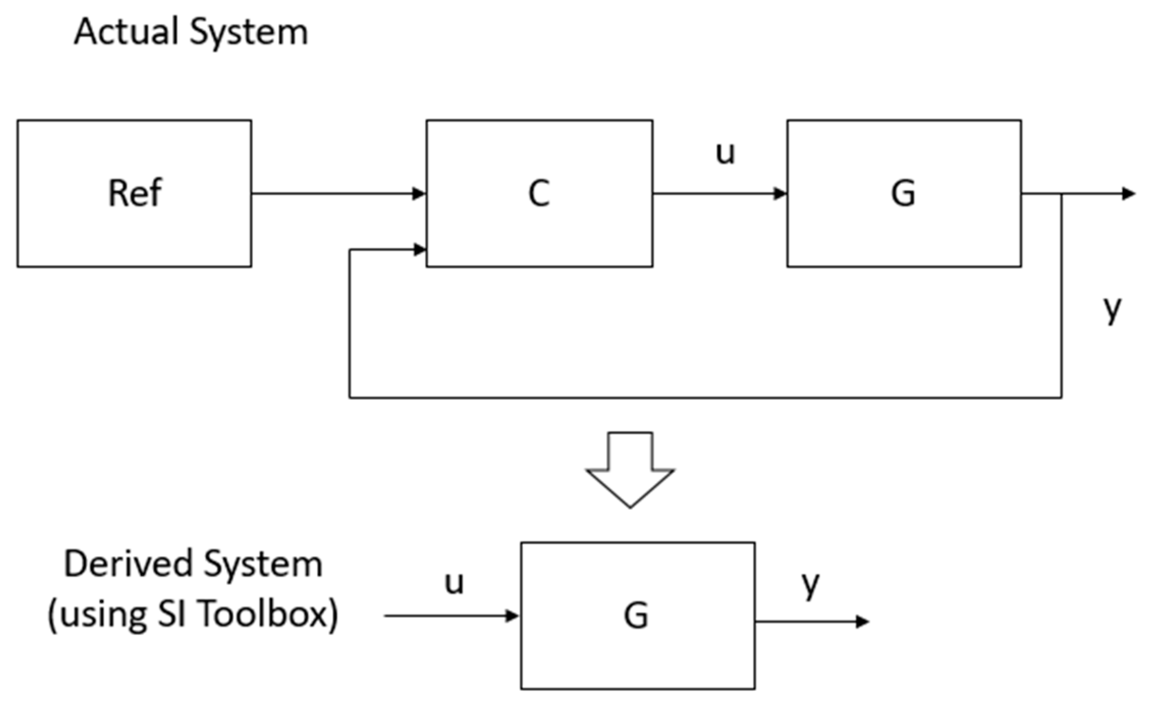
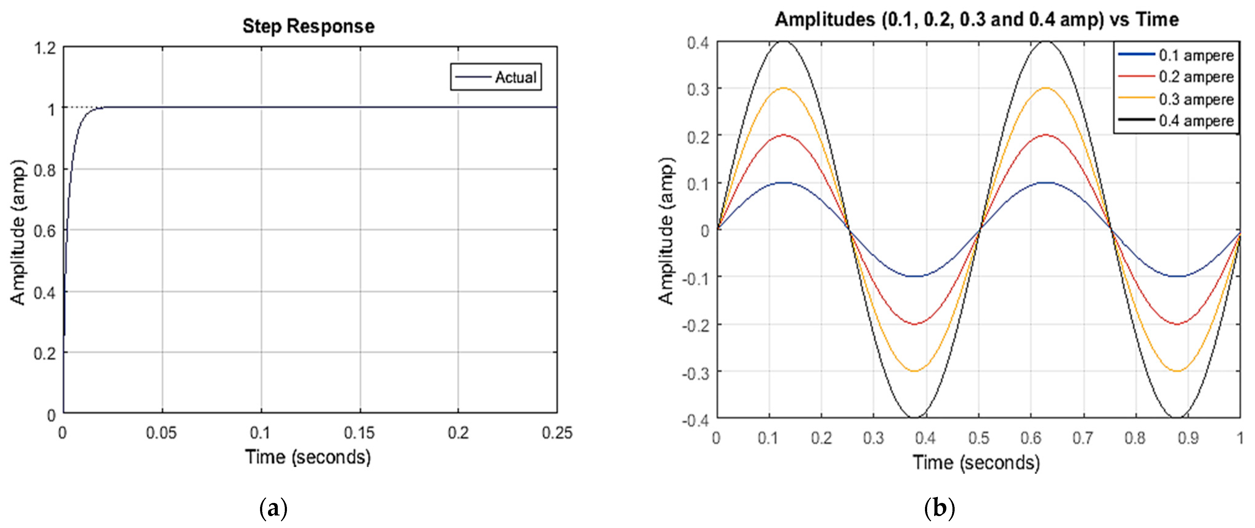
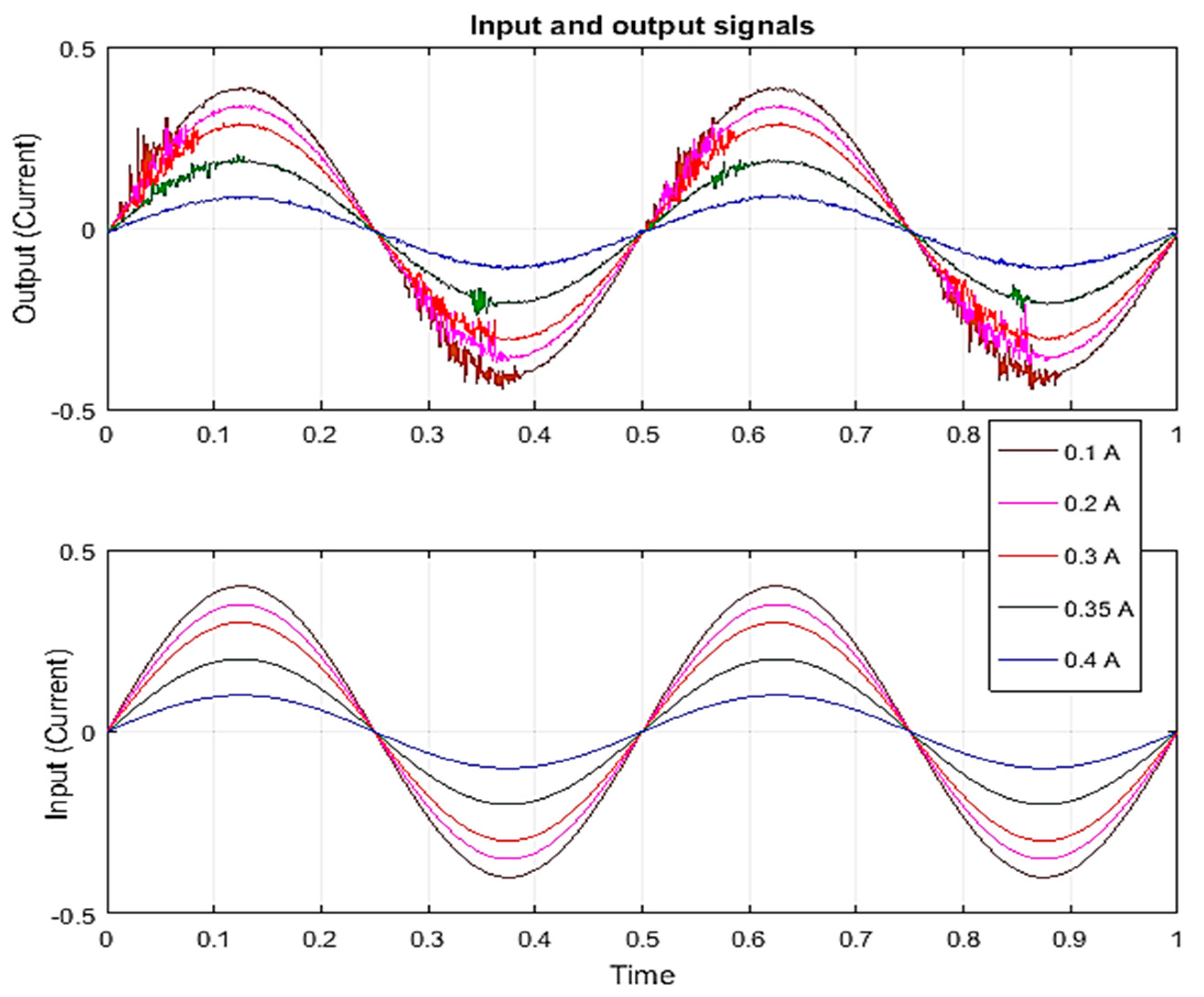
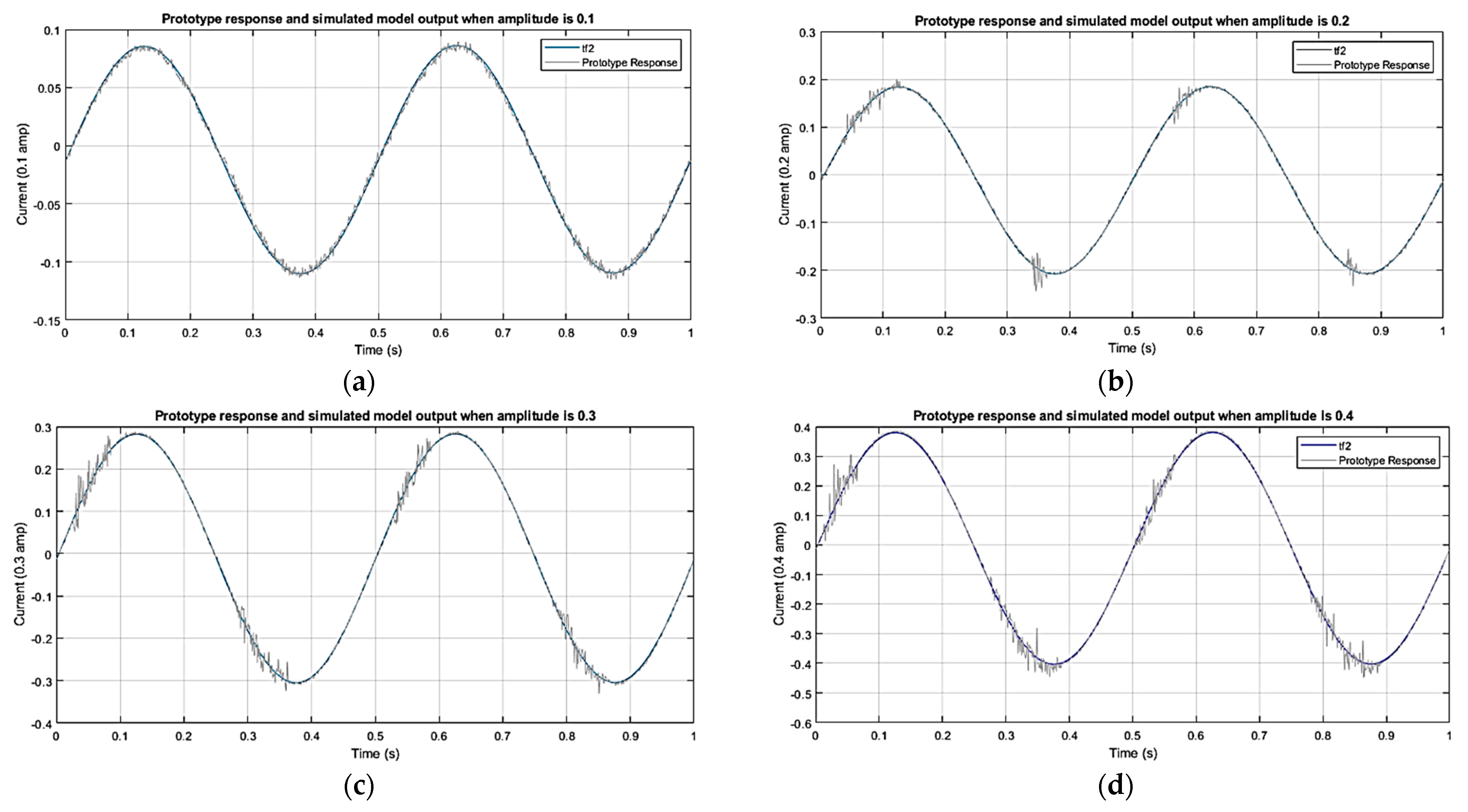
2.3. System Identification

System identification is a simple and convenient method of representing a linear or nonlinear model. This approach is commonly used in control engineering to design a system where the parameters of a system are unknown and required to be controlled effectively. Both the system’s inputs and outputs are considered in this procedure, and their characteristics are estimated using the variances in the inputs and outputs. In this work, a sine-by-sine method with a periodic band limit has been considered to derive the transfer function, as shown in Equation (4). In this process, time and frequency domains have been considered.
I ( t ) = I 0 sin ( ω f t )
where, I , I 0 and ω f are the motor current, signal amplitude with the range of [−0.4–0.4] and frequency (that is 4π) respectively at sampling time t .
Figure 3 depicts some amplitude-varying inputs to the system as well as the system’s output. To accomplish the system responses of different sine waves with different amplitudes, the MATLAB System Identification Toolbox was considered. In addition, several transfer functions have been computed from these responses in order to find the curve that best fits the system responses as shown in Table 1.
Now based on the comparison, this table shows that the performance of Model 2 is satisfactory in all four different amplitudes, such as 0.1, 0.2, 0.3 and 0.4 ampere, where its best fittings are 95.47%, 95.33%, 94.56% and 93.86% respective to the amplitudes. Figure 4 demonstrates the prototype’s responses and the Model 2 responses in the amplitudes for a period of time, 1 s.
However, it is important to highlight that the model is quite different from the motor transfer function, since it has several unknown parameters, includes a controller and is an open loop system. Whenever a controller is considered with a system, it turns into a closed loop system. Hence, the derived system is required to be designed with the proposed controller so that it can offer the same performance as the system shows. It should be noted that the prototype has its own in-built controller and, hence, this study is considering the proposed controller with motor’s transfer function to achieve the prototype’s performance. Figure 5 shows a block diagram that represents the actual system and derived system (using system identification toolbox), where the actual system comprises both the controller and plant in a closed loop system, whereas the derived model (using SI toolbox) includes only the plant.

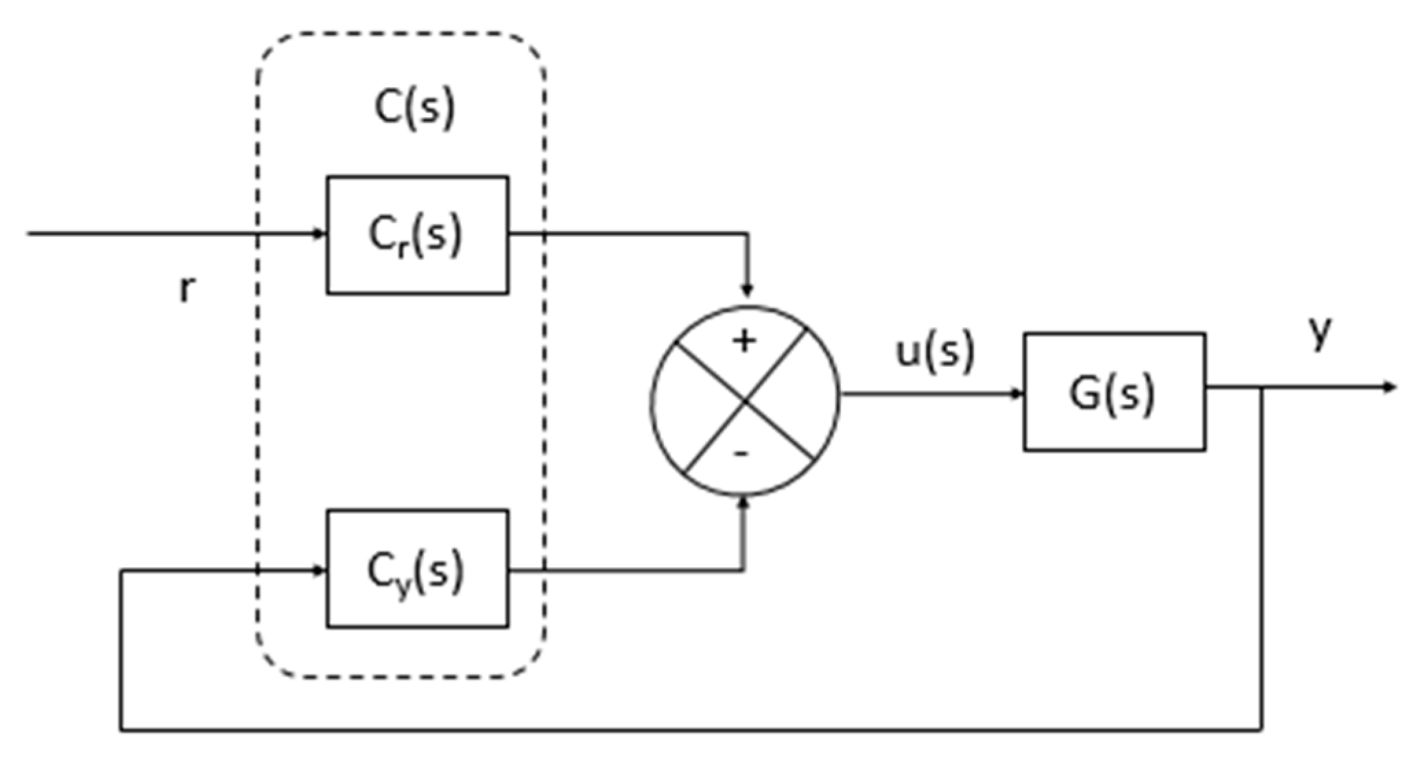
3. Controller Design

3.1. 2DOF PID Controller Design

This study adopts a 2DOF PID controller in order to control the flexion and extension movements of the prototype. Here, the 2DOF PID controller receives a current of different amplitudes as control inputs and the system provides the angular displacement and, hence, the higher the magnitude that is given to the system, the higher the angular displacement that will be generated by the system. Therefore, if the system does not perform well, the system may bring harm to a patient’s impairment. The 2DOF PID controller primarily includes two controllers, where one controller, Cr(s), is responsible for the reference input and another controller, Cy(s), is responsible for system output of the system, as shown in Figure 6.
Here, the algorithms for both Cr(s) and Cy(s) can be shown as follows in Equations (5) and (6).
C r = a K P + K I s + b K D N + 1 s
C y = K P + K I s + K D N + 1 s
In its algorithm, the set-point weight is considered with the reference because it can reduce overshoot at the set-pint response and, thus, smooth the response [35].
The final control law of the controller can be mentioned as Equation (7).
u = K P ( a . r y ) + K I 1 s ( r y ) + K D N 1 + N 1 s ( b . r y )
Figure 4 represents the revolution of the inertia tensor using a homogeneity transformation and the elbow joint angle in Simulink. The function of the elbow joint model is shown in the figure: the segment and corresponding arm increase gradually.

3.2. Control and Actuation

The controller is programmed on a PC equipped with a PID real-time controller, using MATLAB /Simulink software with a sampling time of 0.001 s. Incremental encoders are used to measure the angular positions.

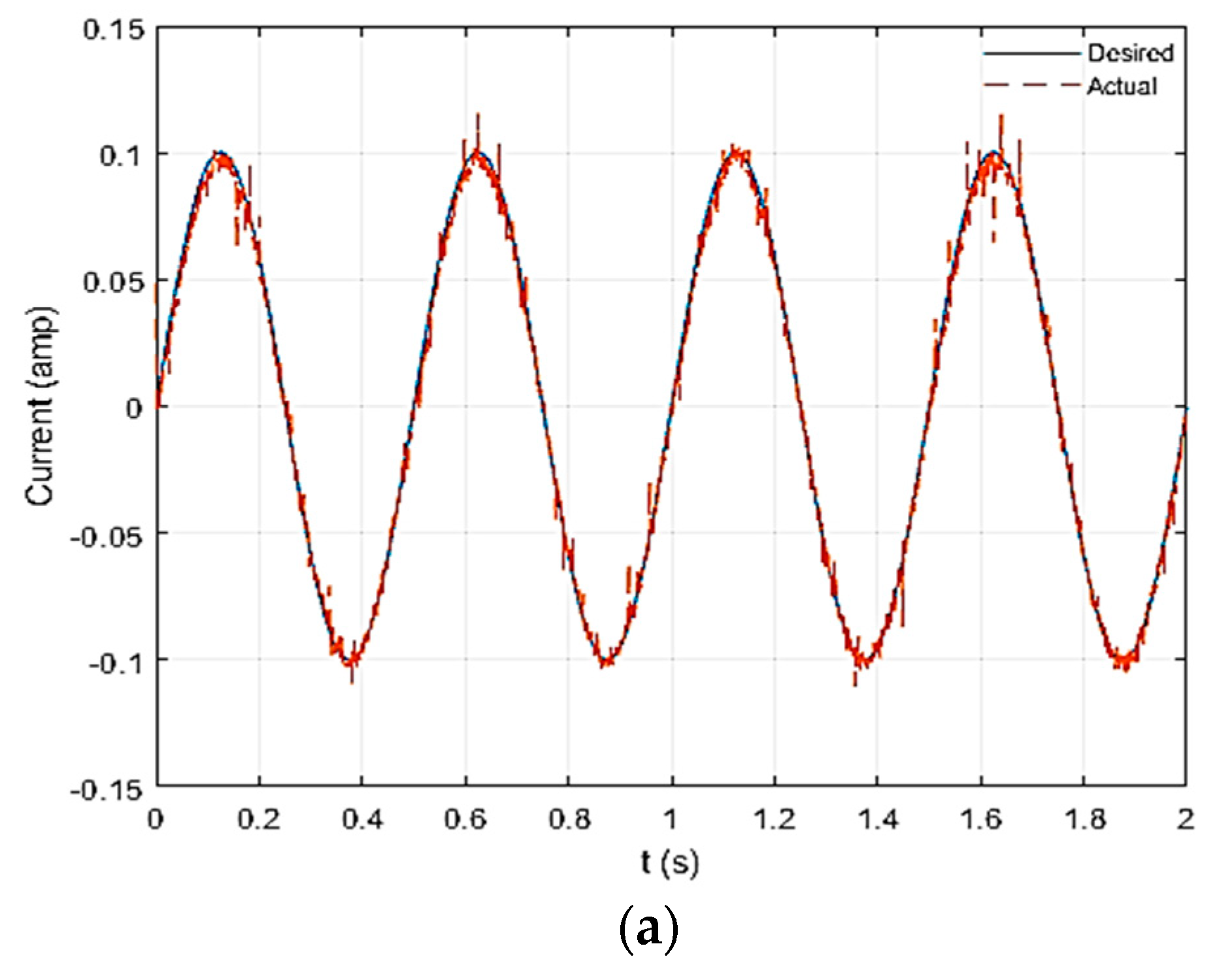
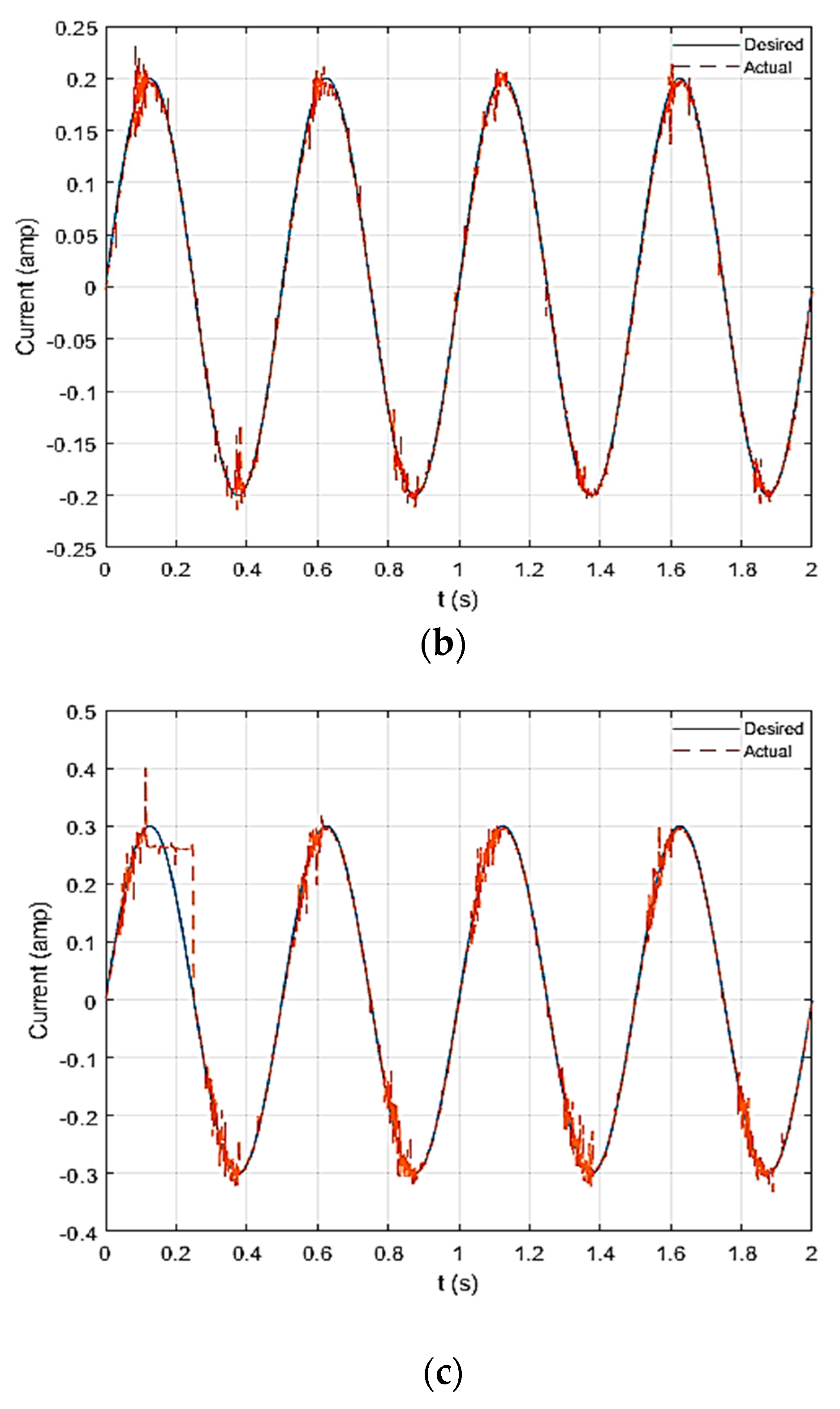
3.3. Controller Performance

Choosing a suitable gain or weight is difficult to do manually, which is why the Simulink Tuning environment has been adopted to choose suitable gains and weights in order to design the controller properly. The controller parameters have been mentioned, as follows, in Table 2.
Table 3 demonstrated the performance of the controller that is quite satisfactory. Here, the rise time and settling time is less than one second and the overshoot is 0%, making the system considerably adjustable for a patient without any jerk or delay.
The performance of the controller on the estimated system with the step response and different amplitudes that have been carried out is shown in Figure 7a and Figure 7b, respectively.

4. Hardware Test

To design the proposed controller, sinusoidal signals of different amplitudes have been considered as references. The sinusoidal signals are designed accordingly, with three amplitudes, such as 0.1, 0.2 and 0.3 amp, and a frequency of 4π Hz. In this system, torque is considered to be the system input and the current is considered to be an output, since the current and voltage are responsible for the motor rotation with certain amount of torques.
From the experiment, it is noticed that the amplitudes of 0.1 and 0.2 amp do not yield much effort to the patient, while the hardware moves very smoothly at 0.3 amp and this amplitude provides enough effort to the patient for elbow flexion and extension, as shown in Figure 8.
In order to evaluate the tracking performance of the controller, the root mean square error (RMSE) method has been considered. RMSE can be expressed by the following Equation [40].
R M S E = | ( i = 1 N ( y a i y e i ) 2 N y ) |
where, y a i = Actual values of y, y e i = Desired values of y and N y = Total number of y.
From Table 4, it can be seen that the controller offers RMSE less than 5%. Hence, for tracking, this controller is suitable for this system.

5. Discussions

The proposed 2DOF controller shows that it is fast in response and in reaching stability. In addition, it does not show any undershoot and overshoot. This is a significant feature for this controller, since the prototype is designed to offer therapy to elbow-impaired patients. In addition, its set-point weight feature helps it to overcome the disturbances to the system rapidly, which is also another important feature of the proposed controller.
The successful development of the controller leads the work towards the hardware implementation. For both the simulation and hardware implementation, different amplitudes of current, such as 0.1 amperes, 0.2 amperes, and 0.3 amperes, have been considered, since the system may deal with patients with different physical conditions. Some patients are frail and feeble in their elbow movements, whereas some patients are capable of moving their elbows, but they need basic mechanical assistance and, hence, they need assistance accordingly of different amplitudes. In general, 0.3 amp is typically reserved for those who are unable to stretch or flex on their own, while 0.1 amp is reserved for those who can move but sometimes need a small amount of assistance from the machine. The proposed controller also performs surprisingly well with negligible tracking errors. However, the experimental work has been carried out only considering the periodic movement of the machine elbow, although this work would benefit from including the responses from the patients. We provide the following limitations of our study, which will be addressed in future works that take our tool and method selection into account:
  • Our study did not examine the proposed model’s compatibility with the existing 2DOF PID controller. From a translational standpoint, future research should prioritize examining the possibility of bridging that gap.
  • At the time of writing, the global pandemic (SARS-CoV-2) caused a challenge in assessing the clinical experiment designed to evaluate the suggested PID controller’s performance.
  • We considered only single-degree elbow movement, although performance can differ when multiple-degree elbow movement is included.

6. Conclusions

In this study, a 2DOF PID controller is designed for a revolute joint of an existing upper limb rehabilitation prototype. Since the system parameters are unknown, the black box system identification technique is considered to estimate the open loop system. Interestingly, the open loop transfer function of the system includes a controller with the plant. Therefore, a transfer function for the motor of revolute joint is derived mathematically that can play as the role of the system. In order to make the motor transfer function behave similarly to the estimated open loop transfer function, the proposed 2DOF controller is implemented with the motor transfer function through a closed loop architecture.
From the simulation and experimental work, the proposed 2DOF PID controller appears to be a suitable controller for single-degree elbow movement. In the future, the controller’s performance in the presence of disturbance and noise will be tested and adjusted appropriately, considering patients’ physical ability.

Author Contributions

Conceptualization, R.R., M.R., M.I.; methodology, R.R., M.I., M.R., S.M.; software, R.R., M.R., M.I.; validation, R.R., S.M.; writing—original draft preparation, R.R., M.R., M.I.; writing—review and editing, M.M.A., M.T.A., M.A.P.M., A.Z.K., Z.S.; visualization, M.M.A., M.T.A., M.A.P.M., A.Z.K., Z.S.; supervision, S.M. All authors have read and agreed to the published version of the manuscript.

Funding

This research received no external funding.

Institutional Review Board Statement

Not applicable.

Informed Consent Statement

Not applicable.

Data Availability Statement

Not applicable.

Acknowledgments

Not applicable.

Conflicts of Interest

The authors declare no conflict of interest.

Nomenclature

T 1 load torque
T m Generated torque
V b back emf
i a armature current
k b back emf constant
k m Torque Constant
ω m amplitude of mass
aSet point weight for proportional part
bSet point weight for derivative part
DDerivative
IIntegral
Larmature inductance
NFilter coefficient
PProportional gain
Rarmature resistance
Varmature voltage

References

  1. Yang, C.; Zhang, J.; Chen, Y.; Dong, Y.; Zhang, Y. A review of exoskeleton-type systems and their key technologies. Proc. Inst. Mech. Eng. Part C J. Mech. Eng. Sci. 2008, 222, 1599–1612. [Google Scholar] [CrossRef]
  2. Jayaraman, A.; Marinov, B.; Singh, Y.; Burt, S.; Rymer, W.Z. Current Evidence for Use of Robotic Exoskeletons in Rehabilitation. In Wearable Robotics; Elsevier: Amsterdam, The Netherlands, 2020; pp. 301–310. [Google Scholar]
  3. Bao, G.; Pan, L.; Fang, H.; Wu, X.; Yu, H.; Cai, S.; Yu, B.; Wan, Y. Academic review and perspectives on robotic exoskeletons. IEEE Trans. Neural Syst. Rehabil. Eng. 2019, 27, 2294–2304. [Google Scholar] [CrossRef] [PubMed]
  4. Kazerooni, H.; Errico, N.J.; Fearing, K.M.; Tung, W.Y.-W. Exoskeleton Support Mechanism for a Medical Exoskeleton. U.S. Patents 10,709,633, 14 July 2020. [Google Scholar]
  5. Almeida, H.A.; Costa, A.F.; Ramos, C.; Torres, C.; Minondo, M.; Bártolo, P.J.; Nunes, A.; Kemmoku, D.; da Silva, J.V.L. Additive manufacturing systems for medical applications: Case studies. In Additive Manufacturing–Developments in Training and Education; Springer: Berlin/Heidelberg, Germany, 2019; pp. 187–209. [Google Scholar]
  6. Crowell, H.P.; Park, J.-H.; Haynes, C.A.; Neugebauer, J.M.; Boynton, A.C. Design, evaluation, and research challenges relevant to exoskeletons and exosuits: A 26-year perspective from the US Army Research Laboratory. IISE Trans. Occup. Ergon. Hum. Factors 2019, 7, 199–212. [Google Scholar] [CrossRef]
  7. Knapik, J.J.; Reynolds, K.L.; Harman, E. Soldier load carriage: Historical, physiological, biomechanical, and medical aspects. Mil. Med. 2004, 169, 45–56. [Google Scholar] [CrossRef] [PubMed] [Green Version]
  8. Näf, M.B.; Koopman, A.S.; Baltrusch, S.; Rodriguez-Guerrero, C.; Vanderborght, B.; Lefeber, D. Passive back support exoskeleton improves range of motion using flexible beams. Front. Robot. AI 2018, 5, 72. [Google Scholar] [CrossRef] [PubMed] [Green Version]
  9. Walsh, C.J.; Endo, K.; Herr, H. A quasi-passive leg exoskeleton for load-carrying augmentation. Int. J. Hum. Robot. 2007, 4, 487–506. [Google Scholar] [CrossRef]
  10. Fontana, M.; Vertechy, R.; Marcheschi, S.; Salsedo, F.; Bergamasco, M. The body extender: A full-body exoskeleton for the transport and handling of heavy loads. IEEE Robot. Autom. Mag. 2014, 21, 34–44. [Google Scholar] [CrossRef]
  11. Adarraga, J.M. Safety and Control Exoskeleton for Snow Skiing. U.S. Patents 8,060,945, 22 November 2011. [Google Scholar]
  12. Li, Z.; Xie, H.; Li, W.; Yao, Z. Proceeding of human exoskeleton technology and discussions on future research. Chin. J. Mech. Eng. 2014, 27, 437–447. [Google Scholar] [CrossRef]
  13. Lee, H.; Kim, W.; Han, J.; Han, C. The technical trend of the exoskeleton robot system for human power assistance. Int. J. Precis. Eng. Manuf. 2012, 13, 1491–1497. [Google Scholar] [CrossRef]
  14. Young, A.J.; Ferris, D.P. State of the art and future directions for lower limb robotic exoskeletons. IEEE Trans. Neural Syst. Rehabil. Eng. 2016, 25, 171–182. [Google Scholar] [CrossRef] [PubMed]
  15. Cheng, X.; Mei, X.; Hu, Y.; Fang, Y.; Wu, S.; You, F.; Kuang, S. Development of an E-Health App for Lower Limb Postoperative Rehabilitation Based on Plantar Pressure Analysis. Appl. Sci. 2018, 8, 766. [Google Scholar] [CrossRef] [Green Version]
  16. Russo, M.; Ceccarelli, M. Analysis of a Wearable Robotic System for Ankle Rehabilitation. Machines 2020, 8, 48. [Google Scholar] [CrossRef]
  17. Fazekas, G.; Horvath, M.; Troznai, T.; Toth, A. Robot-mediated upper limb physiotherapy for patients with spastic hemiparesis: A preliminary study. J. Rehabil. Med. 2007, 39, 580–582. [Google Scholar] [CrossRef] [Green Version]
  18. Gull, M.A.; Bai, S.; Bak, T. A review on design of upper limb exoskeletons. Robotics 2020, 9, 16. [Google Scholar] [CrossRef] [Green Version]
  19. Tucan, P.; Gherman, B.; Major, K.; Vaida, C.; Major, Z.; Plitea, N.; Carbone, G.; Pisla, D. Fuzzy logic-based risk assessment of a parallel robot for elbow and wrist rehabilitation. Int. J. Environ. Res. Public Health 2020, 17, 654. [Google Scholar] [CrossRef] [PubMed] [Green Version]
  20. Chen, C.-T.; Lien, W.-Y.; Chen, C.-T.; Wu, Y.-C. Implementation of an upper-limb exoskeleton robot driven by pneumatic muscle actuators for rehabilitation. Actuators 2020, 9, 106. [Google Scholar] [CrossRef]
  21. Takubo, T.; Arai, T.; Inoue, K.; Ochi, H.; Konishi, T.; Tsurutani, T.; Hayashibara, Y.; Koyanagi, E. Integrated limb mechanism robot ASTERISK. J. Robot. Mechatron. 2006, 18, 203–214. [Google Scholar] [CrossRef]
  22. Tang, Z.; Zhang, K.; Sun, S.; Gao, Z.; Zhang, L.; Yang, Z. An upper-limb power-assist exoskeleton using proportional myoelectric control. Sensors 2014, 14, 6677–6694. [Google Scholar] [CrossRef] [PubMed] [Green Version]
  23. Agarwal, P.; Fox, J.; Yun, Y.; O’Malley, M.K.; Deshpande, A.D. An index finger exoskeleton with series elastic actuation for rehabilitation: Design, control and performance characterization. Int. J. Robot. Res. 2015, 34, 1747–1772. [Google Scholar] [CrossRef]
  24. Vikartovska, Z.; Kuricova, M.; Farbakova, J.; Liptak, T.; Mudronova, D.; Humenik, F.; Madari, A.; Maloveska, M.; Sykova, E.; Cizkova, D. Stem Cell Conditioned Medium Treatment for Canine Spinal Cord Injury: Pilot Feasibility Study. Int. J. Mol. Sci. 2020, 21, 5129. [Google Scholar] [CrossRef] [PubMed]
  25. Song, Z.; Zhang, S. Preliminary study on continuous recognition of elbow flexion/extension using sEMG signals for bilateral rehabilitation. Sensors 2016, 16, 1739. [Google Scholar] [CrossRef] [Green Version]
  26. Zhang, S.; Fu, Q.; Guo, S.; Fu, Y. Coordinative motion-based bilateral rehabilitation training system with exoskeleton and haptic devices for biomedical application. Micromachines 2019, 10, 8. [Google Scholar] [CrossRef] [Green Version]
  27. Copaci, D.; Serrano, D.; Moreno, L.; Blanco, D. A high-level control algorithm based on sEMG signalling for an elbow joint SMA exoskeleton. Sensors 2018, 18, 2522. [Google Scholar] [CrossRef] [Green Version]
  28. Rahman, M.H.; Saad, M.; Kenné, J.P.; Archambault, P.S. Nonlinear sliding mode control implementation of an upper limb exoskeleton robot to provide passive rehabilitation therapy. In Proceedings of the International Conference on Intelligent Robotics and Applications, Yantai, China, 22–25 October 2021; pp. 52–62. [Google Scholar]
  29. Yu, W.; Rosen, J.; Li, X. PID admittance control for an upper limb exoskeleton. In Proceedings of 2011 American Control Conference; IEEE: San Francisco, CA, USA, 2011; pp. 1124–1129. [Google Scholar]
  30. Su, H.; Li, Z.; Li, G.; Yang, C. EMG-Based neural network control of an upper-limb power-assist exoskeleton robot. In International Symposium on Neural Networks; Springer: Berlin/Heidelberg, Germany, 2013; pp. 204–211. [Google Scholar]
  31. Kim, J.-Y.; Park, G.; Lee, S.-A.; Nam, Y. Analysis of machine learning-based assessment for elbow spasticity using inertial sensors. Sensors 2020, 20, 1622. [Google Scholar] [CrossRef] [Green Version]
  32. Nguyen, H.T.; Trinh, V.C.; Le, T.D. An adaptive fast terminal sliding mode controller of exercise-assisted robotic arm for elbow joint rehabilitation featuring pneumatic artificial muscle actuator. Actuators 2020, 9, 118. [Google Scholar] [CrossRef]
  33. Palm, R.; Iliev, B. Learning of grasp behaviors for an artificial hand by time clustering and Takagi-Sugeno modeling. In Proceedings of the 2006 IEEE International Conference on Fuzzy Systems; IEEE: Vancouver, BC, Canada, 2006; pp. 291–298. [Google Scholar]
  34. Gulletta, G.; Erlhagen, W.; Bicho, E. Human-like arm motion generation: A Review. Robotics 2020, 9, 102. [Google Scholar] [CrossRef]
  35. Visioli, A. Practical PID Control; Springer Science & Business Media: Berlin/Heidelberg, Germany, 2006. [Google Scholar]
  36. Kafuko, M.; Wanyama, T. Integrated hands-on and remote PID tuning laboratory. In Proceedings of the Canadian Engineering Education Association (CEEA), Hamilton, ON, Canada, 31 May–3 June 2015; McMaster University. [Google Scholar]
  37. Mounis, S.Y.A.; Azlan, N.Z.; Fatai, S. Optimal Linear Quadratic Gaussian Torque Controller (LQG) for Upper Limb Rehabilitation. In Proceedings of 2019 7th International Conference on Mechatronics Engineering (ICOM); IEEE: Putrajaya, Malaysia, 2019; pp. 1–6. [Google Scholar]
  38. Mounis, S.Y.; Azlan, N.Z.; Sado, F. Assist-as-needed robotic rehabilitation strategy based on Z-spline estimated functional ability. IEEE Access 2020, 8, 157557–157571. [Google Scholar] [CrossRef]
  39. Sado, F.; Na’im Sidek, S.; Yusuf, H.M. Independent Joint Control of a 3-DOF Robotic System Using PI Controller. In Proceedings of the 2014 International Conference on Computer and Communication Engineering; IEEE: Kuala Lumpur, Malaysia, 2014; pp. 115–118. [Google Scholar]
  40. Islam, M.; Okasha, M.; Sulaeman, E. A model predictive control (MPC) approach on unit quaternion orientation based quadrotor for trajectory tracking. Int. J. Control Autom. Syst. 2019, 17, 2819–2832. [Google Scholar] [CrossRef]
Figure 1. The upper limb exoskeleton prototype [38].
Applsci 11 08617 g001
Figure 2. Block diagram of revolute joint of the prototype and its movement range.
Applsci 11 08617 g002
Figure 3. Current vs. time.
Applsci 11 08617 g003
Figure 4. Prototype response and Model 2 response in amplitudes (a) 0.1 amp, (b) 0.2 amp, (c) 0.3 amp and (d) 0.4 amp.
Applsci 11 08617 g004
Figure 5. A block diagram of actual and derived (using SI toolbox) elbow revolute joint system.
Applsci 11 08617 g005
Figure 6. A block diagram of 2DOF PID controller.
Applsci 11 08617 g006
Figure 7. The performance of the controller on the estimated system (a) step response (b) sine wave.
Applsci 11 08617 g007
Figure 8. Current vs. time when amplitudes are considered as (a) 0.1amp (b) 0.2 amp and (c) 0.3 amp.
Applsci 11 08617 g008aApplsci 11 08617 g008b
Table 1. Performance comparison of different systems with 0.4 amp current.
ModelTransfer FunctionBest Fit (%) in Different Amplitudes
Amplitude 0.1Amplitude 0.2Amplitude 0.3Amplitude 0.4
1 76.48 s 140.3 s 2 + 79.65 s + 4.509 95.9194.9294.0593.22
2 358.2 s 97.59 s 2 + 365.9 s + 41.73 95.4795.3394.5693.86
3 372.7 s 112.7 s 2 + 378.9 s + 12.13 95.1895.2894.5993.94
4 492.2 s 120.8 s 2 + 500.9 s + 10.5 95.2295.1894.5993.93
5 476.5 s 100.3 s 2 + 481.2 s + 20.2 94.895.1794.5593.98
6 1087 s + 15.11 s 2 + 1091 s + 8.623 94.2994.8894.493.91
7 1.57 × 10 4 s 2 + 3.044 × 10 5 s 5.9 × 10 4 s 4 + 49.42 s 3 + 1.75 × 10 4 s 2 + 3.13 × 10 5 s + 1.46 × 10 5 94.8395.1894.5494.04
8 41.18 s 2 + 1.94 × 10 4 s 7931 s 3 + 28.19 s 2 + 1.98 × 10 4 + 1482 94.8295.1894.5794.02
9 1.89 × 10 4 s 7200 s 3 + 53.95 s 2 + 1.93 × 10 4 s + 0.00015 94.7695.1894.5694.02
10 41.18 s 2 + 1.95 × 10 4 s 7931 s 3 + 28.19 s 2 + 1.98 × 10 4 + 1482 94.8295.1894.5794.02
Table 2. Controller parameters.
Controller ParametersDescriptionValue
P Proportional gain0.5
I Integral gain400
D Derivative gain9.5494 × 10−5
N Filter coefficient23.3961
b Set point weight for proportional part1
c Set point weight for derivative part1
Table 3. Controller performance.
PropertiesPerformance
Rise Time0.0065 s
Settling Time0.9 s
Overshoot0%
Undershoot0%
Table 4. RMSE.
Table 4. RMSE.
Current (amp)0.10.20.3
RMSE (%)2.5%1.4%0.65%
Publisher’s Note: MDPI stays neutral with regard to jurisdictional claims in published maps and institutional affiliations.

