
Property Analysis of Photo-Polymerization-Type 3D-Printed Structures Based on Multi-Composite Materials


Abstract
:1. Introduction
2. Experimental Details
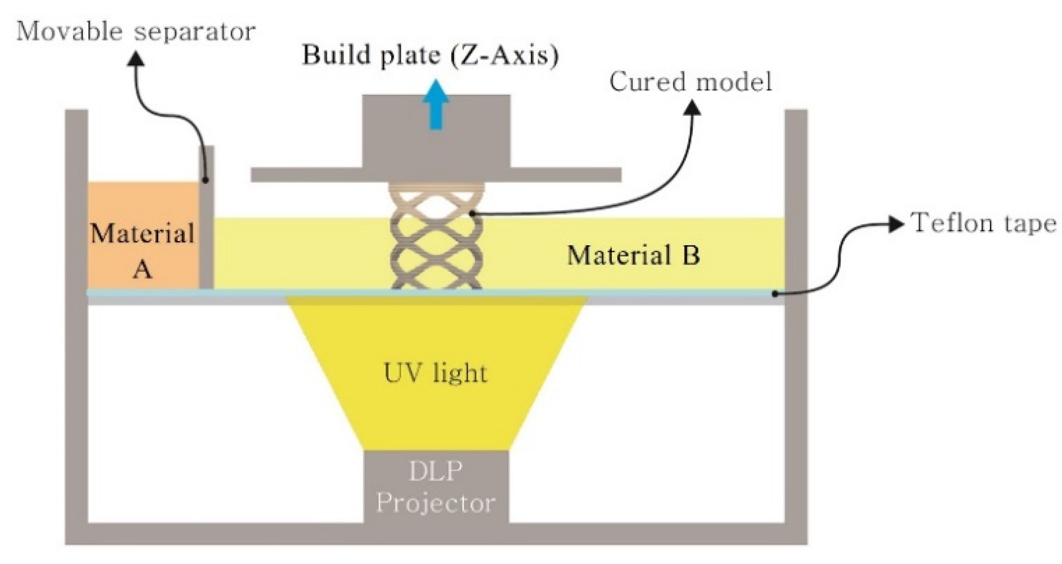
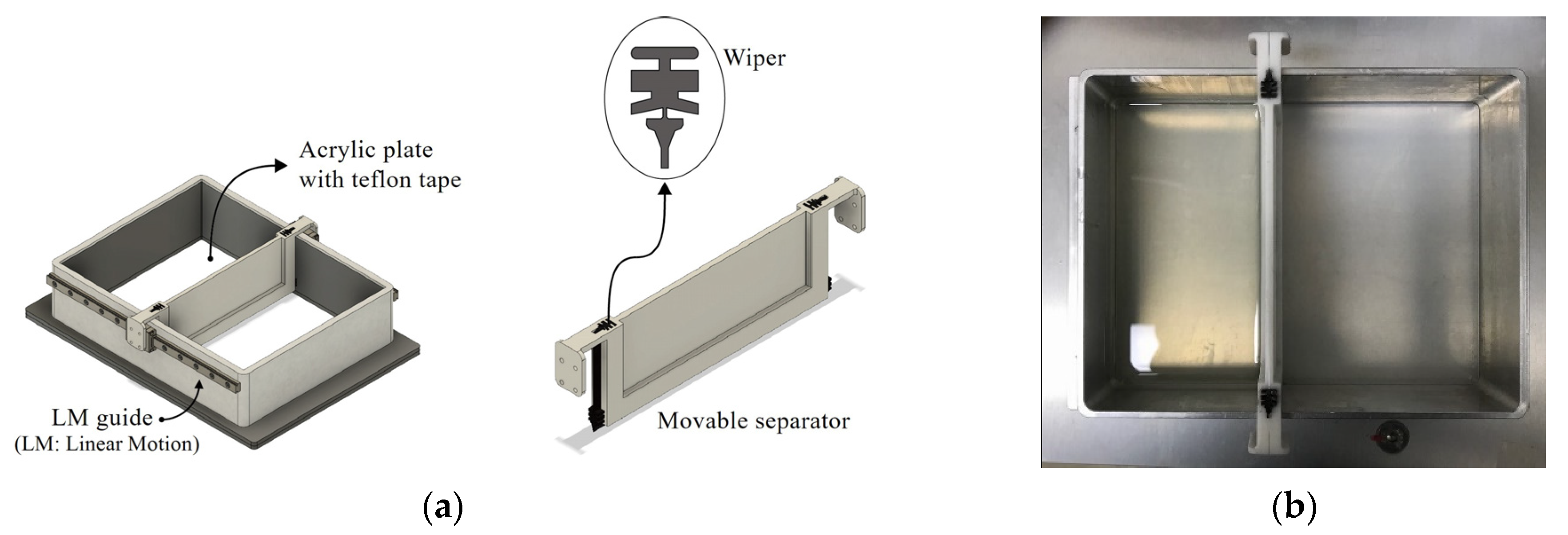
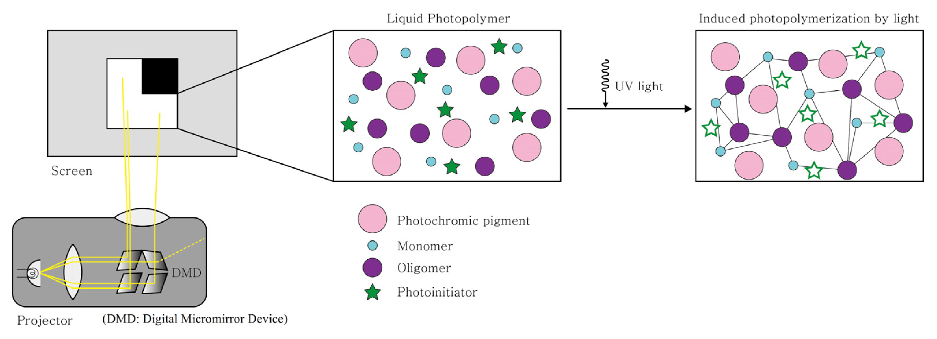
2.1. Experimental Device
2.2. Materials
2.3. Test Methods
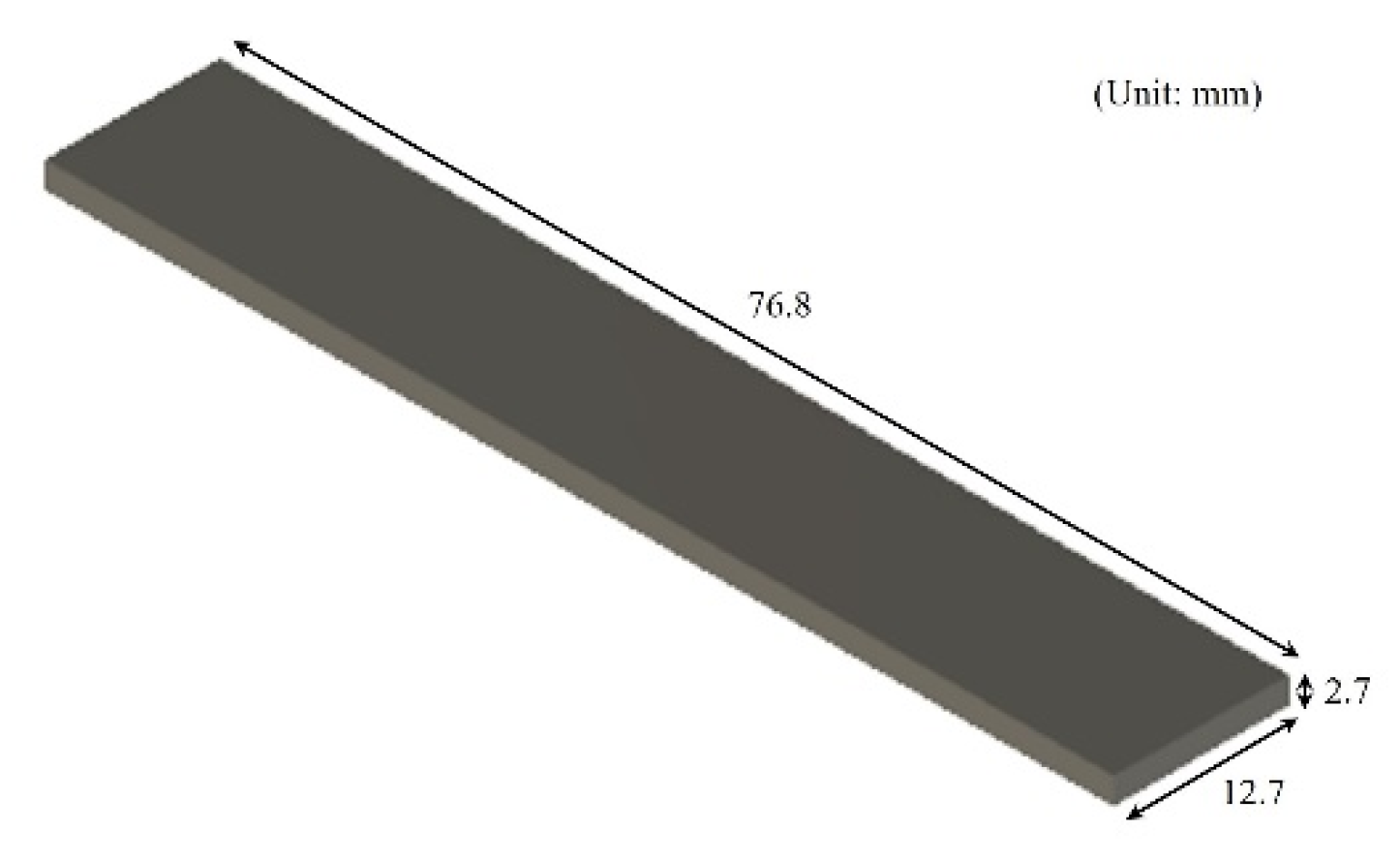
2.3.1. Three-Point Bending Test
2.3.2. Ball Rebound Test
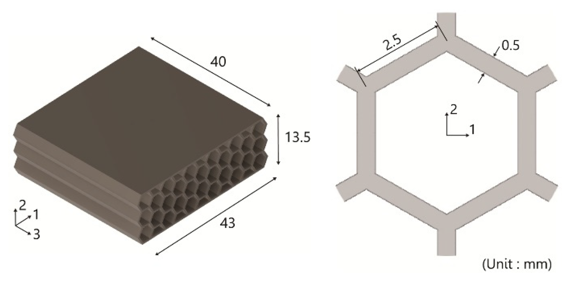
2.3.3. Anisotropic Structure Test
2.3.4. Soft Grippers Test
3. Results and Discussion
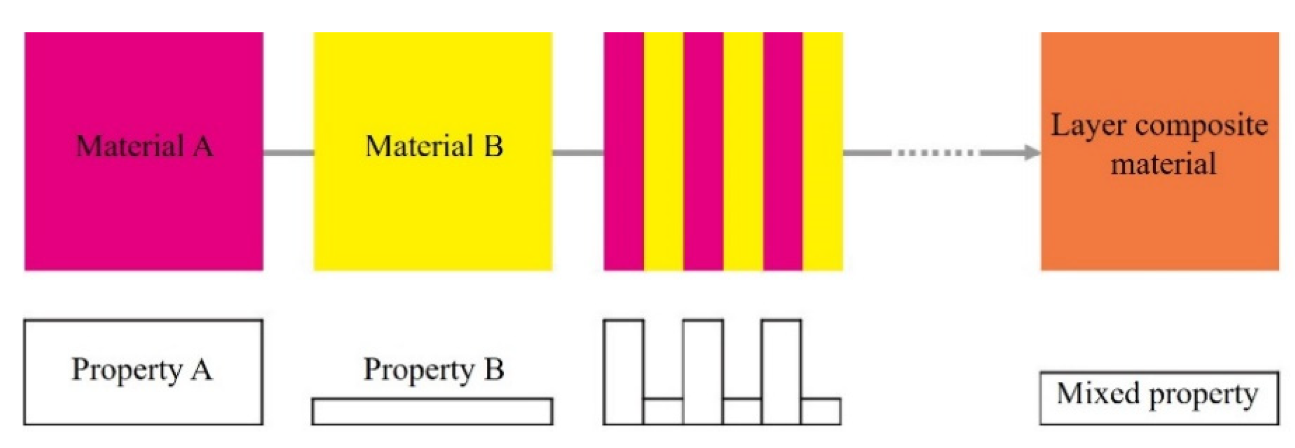
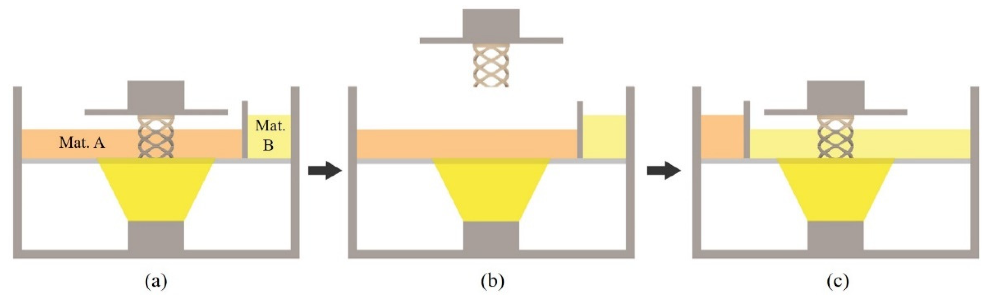
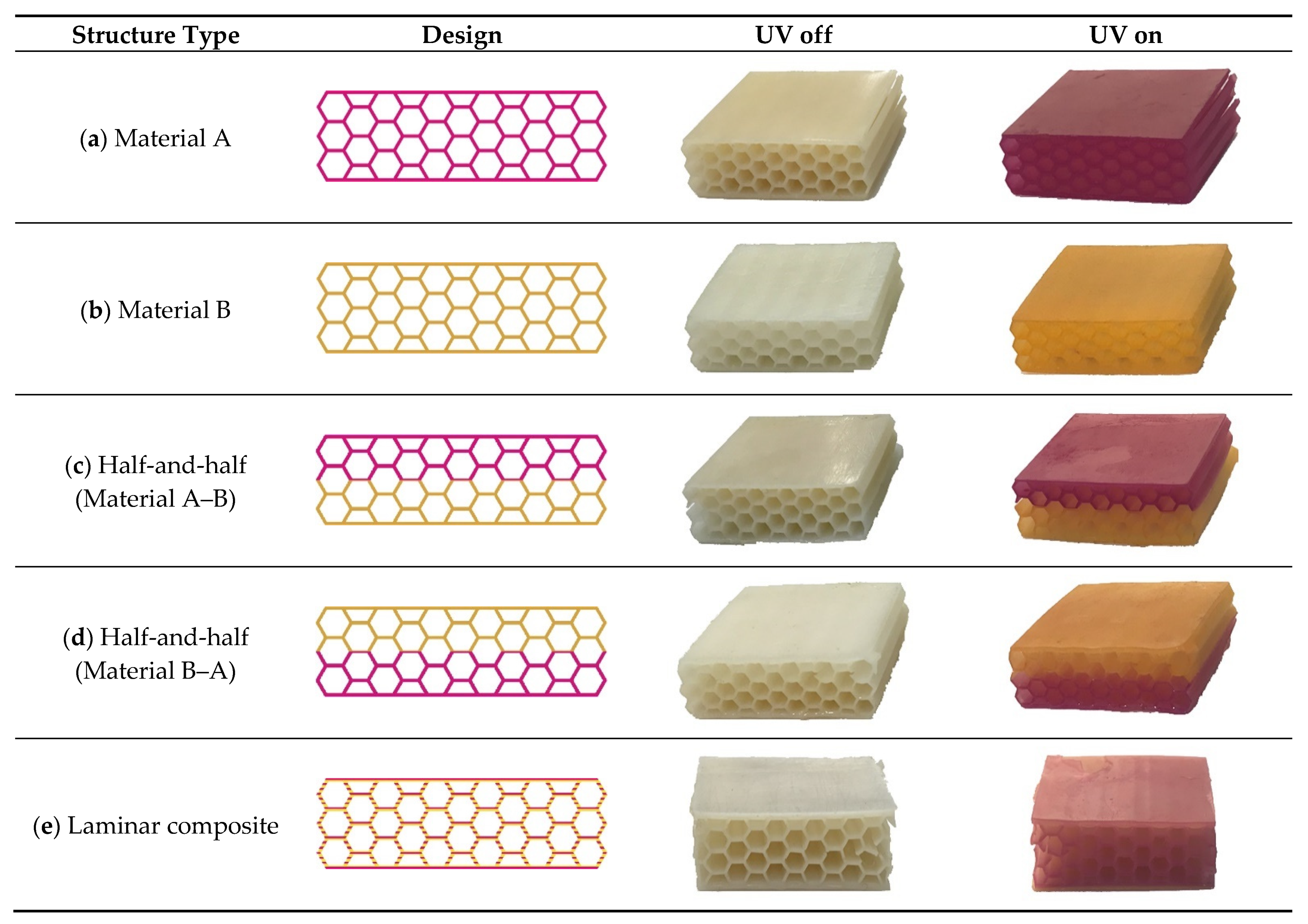
3.1. Laminar Composite Structure
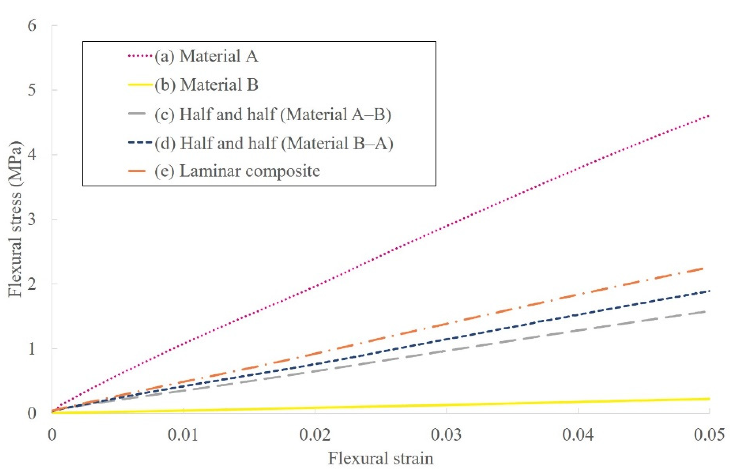
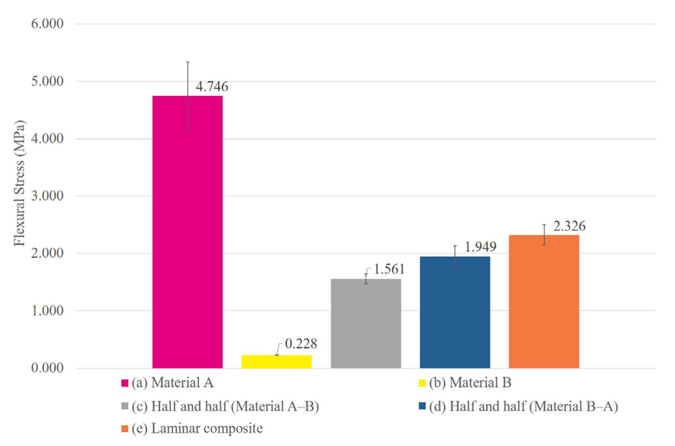
3.2. Three-Point Bending Test
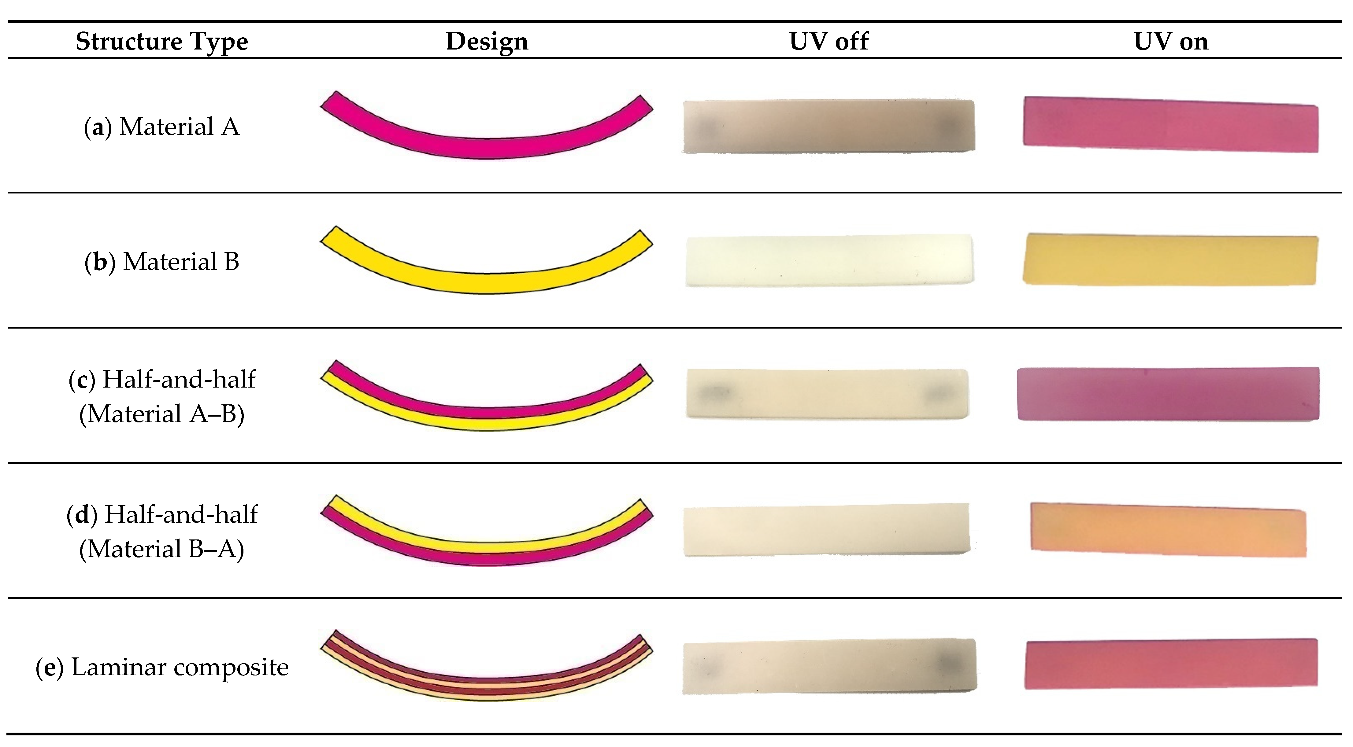
3.2.1. Fabricated Specimens
3.2.2. Test Results
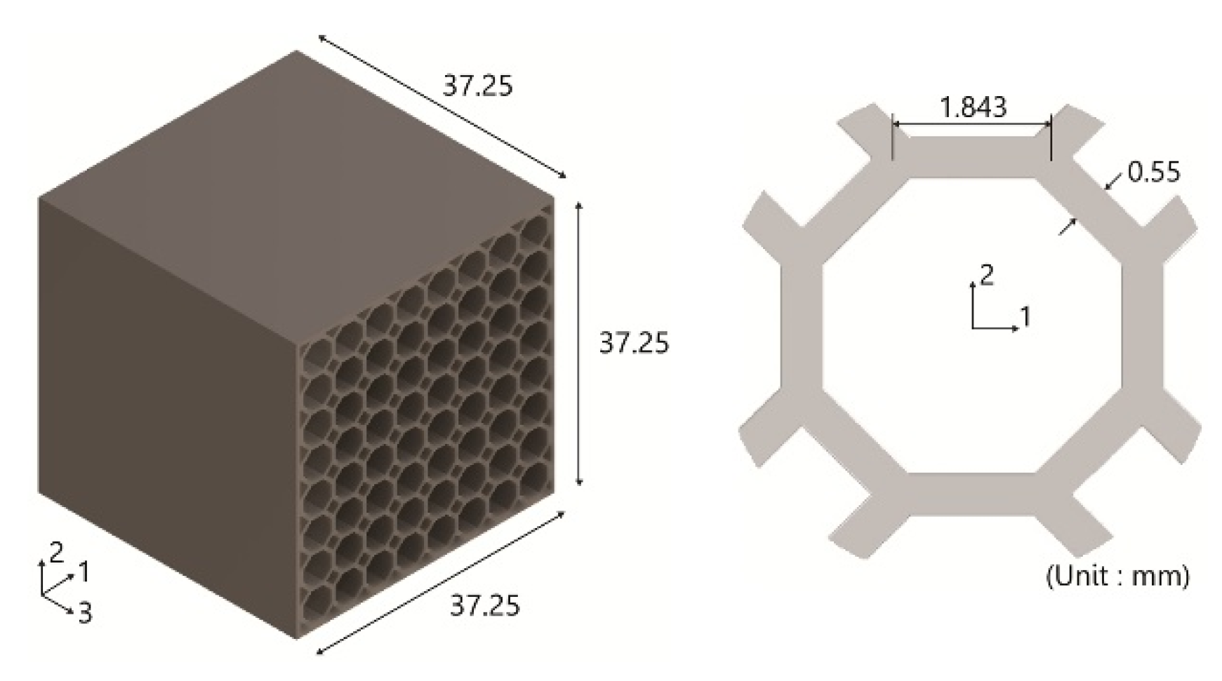
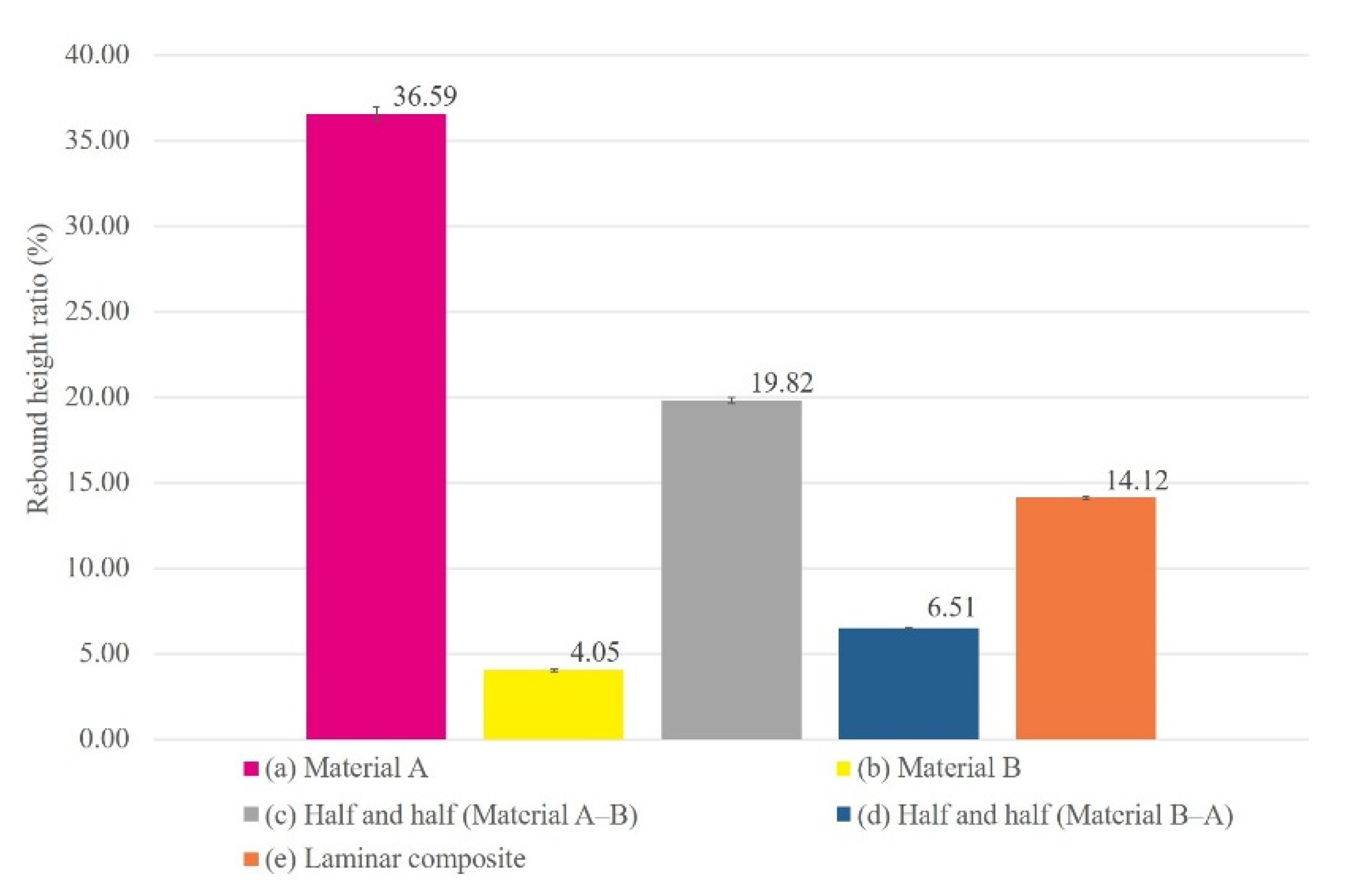
3.3. Ball Rebound Test
3.3.1. Fabricated Specimens
3.3.2. Test Results
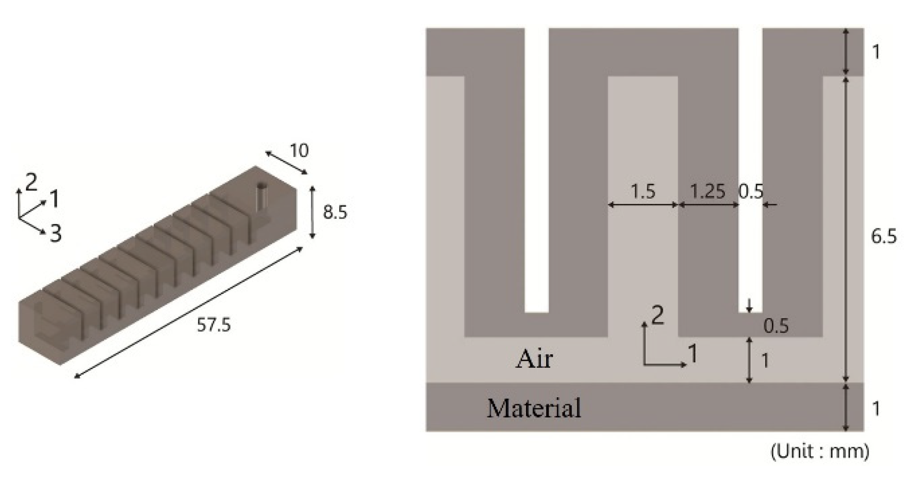
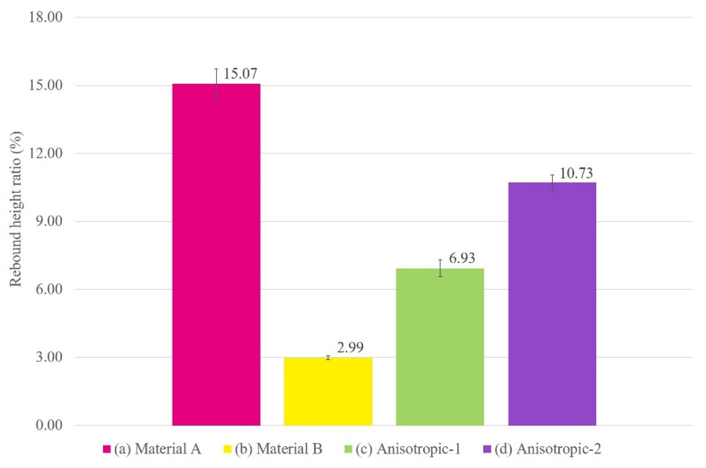
3.4. Anisotropic Structures
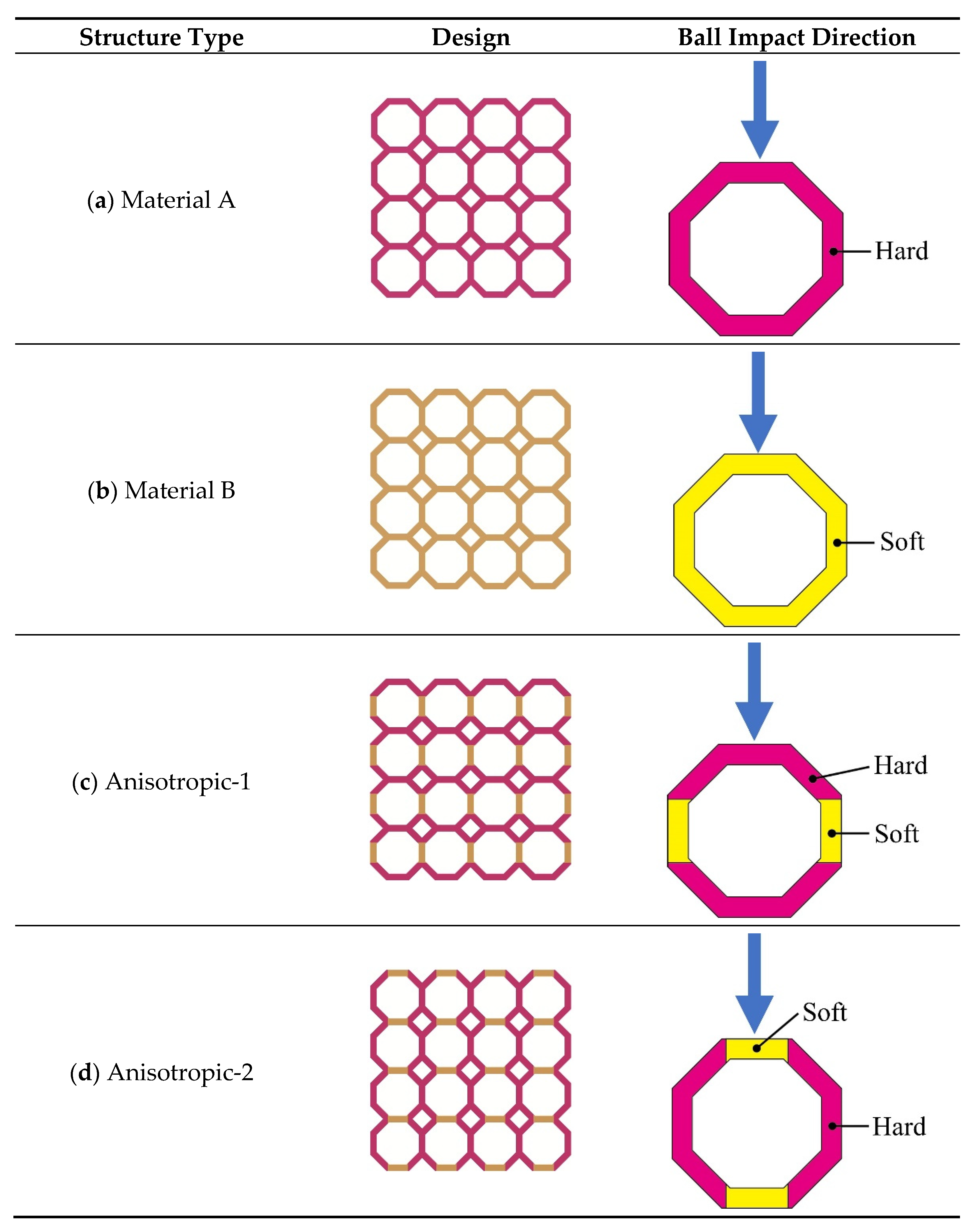
3.4.1. Fabricated Specimens
3.4.2. Test Results
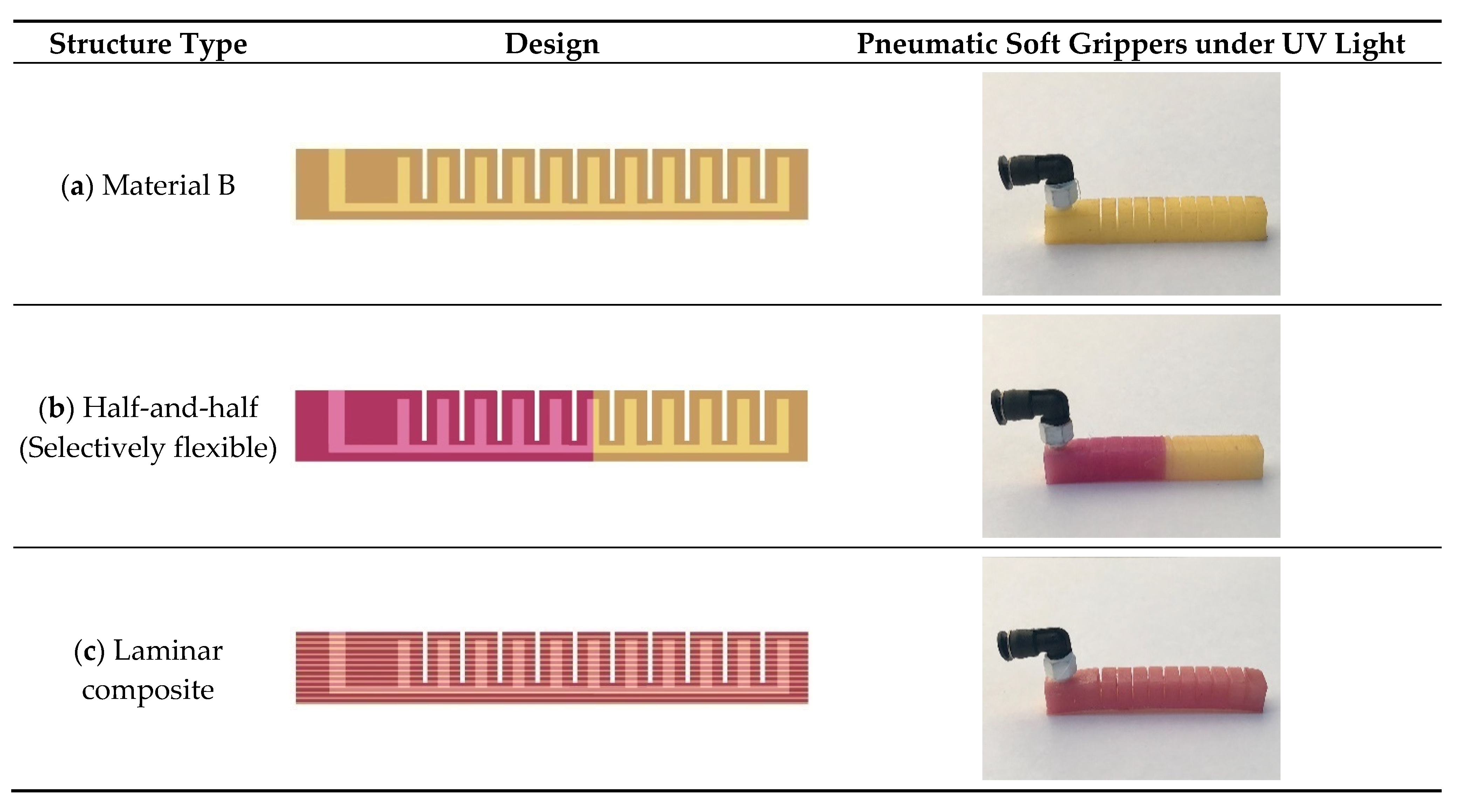
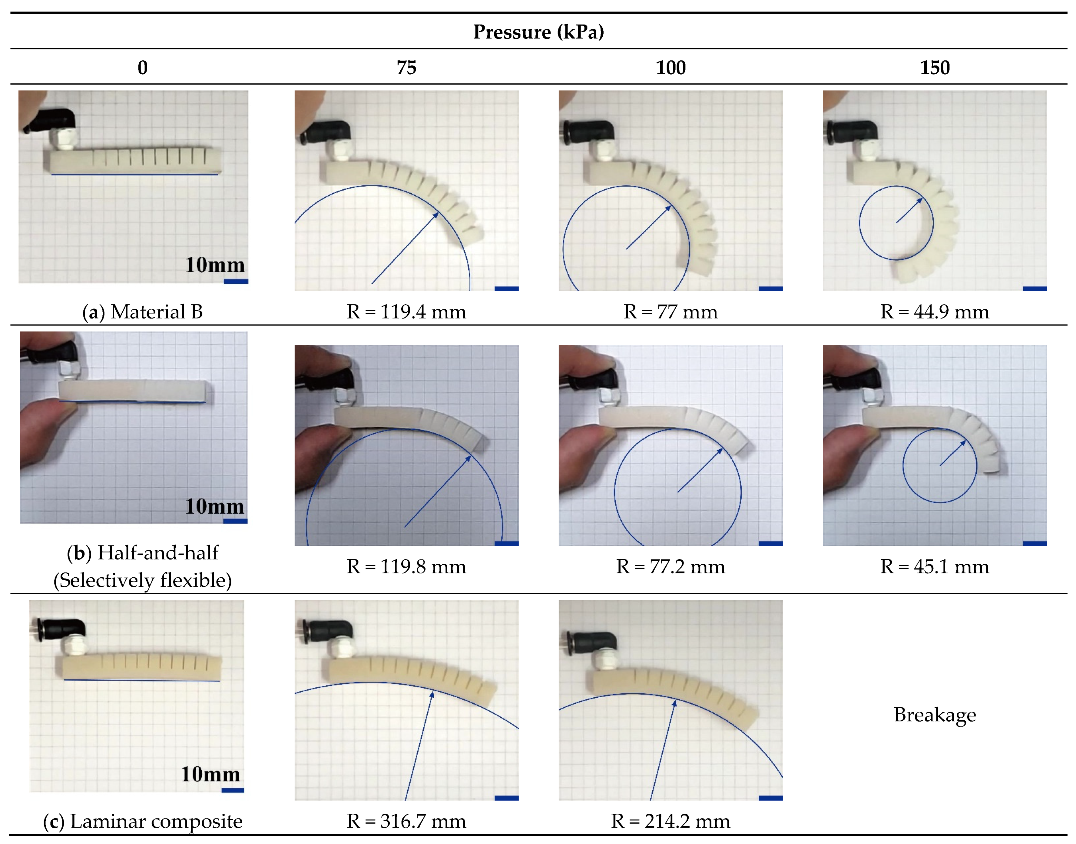
3.5. Soft Grippers
3.5.1. Fabricated Specimens
3.5.2. Test Results
4. Conclusions
Supplementary Materials
Author Contributions
Funding
Institutional Review Board Statement
Informed Consent Statement
Data Availability Statement
Conflicts of Interest
References
- Tymrak, B.M.; Kreiger, M.; Pearce, J.M. Mechanical properties of components fabricated with open-source 3-D printers under realistic environmental conditions. Mater. Des. 2014, 58, 242–246. [Google Scholar] [CrossRef] [Green Version]
- Tran, P.; Ngo, T.D.; Ghazlan, A.; Hui, D. Bimaterial 3D printing and numerical analysis of bio-inspired composite structures under in-plane and transverse loadings. Compos. Part B Eng. 2017, 108, 210–223. [Google Scholar] [CrossRef]
- Sun, Q.; Rizvi, G.M.; Bellehumeur, C.T.; Gu, P. Effect of processing conditions on the bonding quality of FDM polymer filaments. Rapid Prototyp. J. 2008, 14, 72–80. [Google Scholar] [CrossRef]
- Melnikova, R.; Ehrmann, A.; Finsterbusch, K. 3D printing of textile-based structures by Fused Deposition Modelling (FDM) with different polymer materials. In Proceedings of the 2014 Global Conference on Polymer and Composite Materials (PCM 2014), Ningbo, China, 27–29 May 2014; Institute of Physics Publishing: Bristol, England, 2014; Volume 62, p. 012018. [Google Scholar]
- Caulfield, B.; McHugh, P.E.; Lohfeld, S. Dependence of mechanical properties of polyamide components on build parameters in the SLS process. J. Mater. Process. Technol. 2007, 182, 477–488. [Google Scholar] [CrossRef]
- Garcia, C.R.; Correa, J.; Espalin, D.; Barton, J.H.; Rumpf, R.C.; Wicker, R.; Gonzalez, V. 3D printing of anisotropic metamaterials. Prog. Electromagn. Res. Lett. 2012, 34, 75–82. [Google Scholar] [CrossRef] [Green Version]
- Gu, H.; Ma, C.; Gu, J.; Guo, J.; Yan, X.; Huang, J.; Zhang, Q.; Guo, Z. An overview of multifunctional epoxy nanocomposites. J. Mater. Chem. C 2016, 4, 5890–5906. [Google Scholar] [CrossRef]
- Gu, J.; Yang, X.; Lv, Z.; Li, N.; Liang, C.; Zhang, Q. Functionalized graphite nanoplatelets/epoxy resin nanocomposites with high thermal conductivity. Int. J. Heat Mass Transf. 2016, 92, 15–22. [Google Scholar] [CrossRef]
- Dou, J.; Zhang, Q.; Ma, M.; Gu, J. Fast fabrication of epoxy-functionalized magnetic polymer core-shell microspheres using glycidyl methacrylate as monomer via photo-initiated miniemulsion polymerization. J. Magn. Magn. Mater. 2012, 324, 3078–3082. [Google Scholar] [CrossRef]
- Kroll, E.; Artzi, D. Enhancing aerospace engineering students’ learning with 3D printing wind-tunnel models. Rapid Prototyp. J. 2011, 17, 393–402. [Google Scholar] [CrossRef]
- Wong, K.V.; Hernandez, A. A Review of Additive Manufacturing. ISRN Mech. Eng. 2012, 2012, 1–10. [Google Scholar] [CrossRef] [Green Version]
- Short, D.B. Use of 3D printing by museums: Educational exhibits, artifact education, and artifact restoration. 3D Print. Addit. Manuf. 2015, 2, 209–215. [Google Scholar] [CrossRef]
- Murphy, S.V.; Atala, A. 3D bioprinting of tissues and organs. Nat. Biotechnol. 2014, 32, 773–785. [Google Scholar] [CrossRef] [PubMed]
- Wang, X.; Jiang, M.; Zhou, Z.; Gou, J.; Hui, D. 3D printing of polymer matrix composites: A review and prospective. Compos. Part B Eng. 2017, 110, 442–458. [Google Scholar] [CrossRef]
- Shin, I.J.; Park, M.S. Direct Conductive Patterning on 3D Printed Structure Using Laser. Phys. Status Solidi 2018, 215, 1700597. [Google Scholar] [CrossRef]
- Shin, I.; Park, M. 3D printed conductive patterns based on laser irradiation. Phys. Status Solidi Appl. Mater. Sci. 2017, 214. [Google Scholar] [CrossRef]
- Lee, S.; Shin, C.; Jung, M.; Park, M. Property Analysis of Multi-Material Specimen based on ME Type 3D Printer. J. Korean Soc. Precis. Eng. 2020, 37, 231–238. [Google Scholar] [CrossRef]
- Choi, S.; Park, M. Fabrication of Conductive Patterns on 3D Printed Structure Using Photo-Polymerization Technology. Phys. Status Solidi 2019, 216, 1801017. [Google Scholar] [CrossRef]
- Mei, H.; Huang, W.; Liu, H.; Pan, L.; Cheng, L. 3D printed carbon-ceramic structures for enhancing photocatalytic properties. Ceram. Int. 2019, 45, 15223–15229. [Google Scholar] [CrossRef]
- Tsai, M.J.; Mei, C.W.; Cheng, Y.L.; Chen, F.; Hu, Z.Y.; Huang, K.C. A study of a material jetting based color 3d printing system by using multiple piezoelectric heads. In Proceedings of the 2017 International Conference on Machine Learning and Cybernetics, ICMLC, Ningbo, China, 9–12 July 2017; Volume 2, pp. 664–669. [Google Scholar]
- He, Z.; Shao, Z.; Wang, Q.; Zhong, W.; Tao, X. Experimental study of cavitating flow inside vertical multi-hole nozzles with different length-diameter ratios using diesel and biodiesel. Exp. Therm. Fluid Sci. 2015, 60, 252–262. [Google Scholar] [CrossRef]
- Cramer, N.B.; Stansbury, J.W.; Bowman, C.N. Recent advances and developments in composite dental restorative materials. J. Dental Res. 2011, 90, 402–416. [Google Scholar] [CrossRef] [Green Version]
- Song, S.Y.; Park, M.S.; Lee, D.; Lee, J.W.; Yun, J.S. Optimization and characterization of high-viscosity ZrO2 ceramic nanocomposite resins for supportless stereolithography. Mater. Des. 2019, 180. [Google Scholar] [CrossRef]
- Song, S.Y.; Park, M.S.; Lee, J.W.; Yun, J.S. Improvement of dispersion stability and 3D-printing characteristics of ceramics in photopolymers by controlling the coating thickness of silane coupling agents. Mater. Chem. Phys. 2018, 216, 446–453. [Google Scholar] [CrossRef]
- Song, S.Y.; Park, M.S.; Lee, J.W.; Yun, J.S. A study on the rheological and mechanical properties of photo-curable ceramic/polymer composites with different silane coupling agents for SLA 3D printing technology. Nanomaterials 2018, 8, 93. [Google Scholar] [CrossRef] [Green Version]
- Phillips, R. Photopolymerization. J. Photochem. 1984, 25, 79–82. [Google Scholar] [CrossRef]
- Choi, J.W.; Kim, H.C.; Wicker, R. Multi-material stereolithography. J. Mater. Process. Technol. 2011, 211, 318–328. [Google Scholar] [CrossRef]
- Han, D.; Yang, C.; Fang, N.X.; Lee, H. Rapid multi-material 3D printing with projection micro-stereolithography using dynamic fluidic control. Addit. Manuf. 2019, 27, 606–615. [Google Scholar] [CrossRef]
- Li, V.C.F.; Kuang, X.; Hamel, C.M.; Roach, D.; Deng, Y.; Qi, H.J. Cellulose nanocrystals support material for 3D printing complexly shaped structures via multi-materials-multi-methods printing. Addit. Manuf. 2019, 28, 14–22. [Google Scholar] [CrossRef]
- Emon, M.O.F.; Alkadi, F.; Philip, D.G.; Kim, D.H.; Lee, K.C.; Choi, J.W. Multi-material 3D printing of a soft pressure sensor. Addit. Manuf. 2019, 28, 629–638. [Google Scholar] [CrossRef]
- Hwang, S.; Lee, J.; Lee, S.; Hong, D.; Park, M. Development of DLP 3D Printer with Multiple Composite Materials. J. Korean Soc. Precis. Eng. 2020, 37, 381–388. [Google Scholar] [CrossRef]
- Gyak, K.W.; Vishwakarma, N.K.; Hwang, Y.H.; Kim, J.; Yun, H.S.; Kim, D.P. 3D-printed monolithic SiCN ceramic microreactors from a photocurable preceramic resin for the high temperature ammonia cracking process. React. Chem. Eng. 2019, 4, 1393–1399. [Google Scholar] [CrossRef]
- D20-Committee. Standard Test Methods for Flexural Properties of Unreinforced and Reinforced Plastics and Electrical Insulating Materials(ASTM D790-17); ASTM International: West Conshohocken, PA, USA, 2017. [Google Scholar]
- D20-Committee. Standard Test Methods for Flexible Cellular Materials—Slab, Bonded, and Molded Urethane Foams(ASTM D3574-01); ASTM International: West Conshohocken, PA, USA, 2001. [Google Scholar]
- Ge, L.; Dong, L.; Wang, D.; Ge, Q.; Gu, G. A digital light processing 3D printer for fast and high-precision fabrication of soft pneumatic actuators. Sens. Actuators A Phys. 2018, 273, 285–292. [Google Scholar] [CrossRef]
- Ding, L.; Dai, N.; Mu, X.; Xie, S.; Fan, X.; Li, D.; Cheng, X. Design of soft multi-material pneumatic actuators based on principal strain field. Mater. Des. 2019, 182, 108000. [Google Scholar] [CrossRef]
- Herianto; Irawan, W.; Ritonga, A.S.; Prastowo, A. Design and fabrication in the loop of soft pneumatic actuators using fused deposition modelling. Sens. Actuators A Phys. 2019, 298, 111556. [Google Scholar] [CrossRef]
- Yang, C.N.; Chen, T.S. Colored visual cryptography scheme based on additive color mixing. Pattern Recognit. 2008, 41, 3114–3129. [Google Scholar] [CrossRef]
- Udupa, G.; Rao, S.S.; Gangadharan, K.V. Functionally Graded Composite Materials: An Overview. Procedia Mater. Sci. 2014, 5, 1291–1299. [Google Scholar] [CrossRef]
- Correia, V.M.F.; Madeira, J.F.A.; Araújo, A.L.; Soares, C.M.M. Multiobjective optimization of functionally graded material plates with thermo-mechanical loading. Compos. Struct. 2019, 207, 845–857. [Google Scholar] [CrossRef]


| Variables | Values |
|---|---|
| Build size | 134.4 mm × 75.6 mm × 200 mm |
| X-Y pixel resolution | 70 μm |
| Curing power | 3.12 mw/cm2 |
| Layer thickness | 50 μm |
| Material A | Material B | |||
|---|---|---|---|---|
| STD Resin (Hard Material) | C-Red Pigment | Flexible Resin (Soft Material) | C-Yellow Pigment | |
| Weight ratio (%) | 95 | 5 | 95 | 5 |
| UV Exposure Time(s) | |||||||
|---|---|---|---|---|---|---|---|
| 1 | 2 | 3 | 4 | 5 | 6 | 7 | |
| Material A (μm) | 60 | 190 | 230 | 320 | 360 | 390 | 420 |
| Material B (μm) | - | - | 111 | 192 | 271 | 361 | 436 |
Publisher’s Note: MDPI stays neutral with regard to jurisdictional claims in published maps and institutional affiliations. |
© 2021 by the authors. Licensee MDPI, Basel, Switzerland. This article is an open access article distributed under the terms and conditions of the Creative Commons Attribution (CC BY) license (https://creativecommons.org/licenses/by/4.0/).
Share and Cite
Hwang, S.-R.; Park, M.-S. Property Analysis of Photo-Polymerization-Type 3D-Printed Structures Based on Multi-Composite Materials. Appl. Sci. 2021, 11, 8545. https://doi.org/10.3390/app11188545
Hwang S-R, Park M-S. Property Analysis of Photo-Polymerization-Type 3D-Printed Structures Based on Multi-Composite Materials. Applied Sciences. 2021; 11(18):8545. https://doi.org/10.3390/app11188545
Chicago/Turabian StyleHwang, So-Ree, and Min-Soo Park. 2021. "Property Analysis of Photo-Polymerization-Type 3D-Printed Structures Based on Multi-Composite Materials" Applied Sciences 11, no. 18: 8545. https://doi.org/10.3390/app11188545
APA StyleHwang, S.-R., & Park, M.-S. (2021). Property Analysis of Photo-Polymerization-Type 3D-Printed Structures Based on Multi-Composite Materials. Applied Sciences, 11(18), 8545. https://doi.org/10.3390/app11188545