Article

Workspace Analysis of a Mobile Manipulator with Obstacle Avoidance in 3D Printing Tasks

by
Robert Guamán Rivera
1,
Rodrigo García Alvarado
2,
Alejandro Martínez-Rocamora
3 and
Fernando Auat Cheein
1,*
1
Department of Electronics Engineering, Universidad Técnica Federico Santa María, Valparaíso 1680, Chile
2
Department of Design and Theory of Architecture, Universidad de Bio-Bio, Concepción 1202, Chile
3
ArDiTec, Department of Architectural Constructions II, IUACC, Higher Technical School of Building Engineering, Universidad de Sevilla, Av. Reina Mercedes 4-a, 41012 Sevilla, Spain
*
Author to whom correspondence should be addressed.
Appl. Sci. 2021, 11(17), 7923; https://doi.org/10.3390/app11177923
Submission received: 27 July 2021 / Revised: 22 August 2021 / Accepted: 25 August 2021 / Published: 27 August 2021
(This article belongs to the Special Issue New Trends in Robotics, Automation and Mechatronics (RAM))

Abstract

:
The knowledge of the workspace for a robotic system on construction sites represents an essential resource to ensure the work progress, guarantee the safety of the construction tasks, and avoid robot damage. Despite the dramatic development of 3D printing technologies with robotic systems in recent years, these are still several challenges to consider, such as the size of the printing profile and obstacles in the construction site. This work presents the results from evaluating the workspace of a mobile manipulator in 3D printing tasks on construction sites. The methodology analyses the printing workspace based on the workspace of the mobile manipulator, considering fixed obstacles and possible collisions between the robot and obstacles during 3D printing tasks. The results showed that the shape of the printing profile defined as a building element changes the shape of the printing workspace. Furthermore, the obstacles in the construction site and height variation of the printing profile cause changes in the displacement of the robotic platform and values of rotation of its joints, which also modify the shape of the printing workspace.

1. Introduction

Three-dimensional printing (3DP) consists of building a component layer by layer [1]; this technique employs a computer-aided design (CAD) model [2]. Currently, this technology is evolving towards large scale 3D printing, where the main novelty is the use of concrete. In this context, a new technique known as 3D extrusion-based concrete printing (3DCP) emerged [3]. The advantages of 3DCP include reducing the use of labour, improving flexibility in architectural design, and saving costs during the construction process [4].
The construction industry has involved robotic platforms and additive manufacturing techniques to reduce the time required to produce complex geometries. These robotic platforms perform repetitive motions and deposit material uniformly. Furthermore, the robot has structural conditions, dexterity, ability, and flexibility to improve the efficiency of 3D printing [5].
Despite the advantages of robots, positioning these robotic platforms is a great challenge that requires analysis of their workspace, degrees of freedom (DOFs), and perception of the construction environment. There are several methods to evaluate the workspace of a manipulator, through simulation software, manual trials, and error fields tests, which provide information about the constraints of a robot. However, the techniques for workspace evaluation are geometric, iterative, and use analytical methods that can be mathematically complex and computationally expensive [6].
The workspace of an industrial robot is a region of points that the end-effector can reach. The strategy to obtain the optimal workspace considers the kinematic design of the robotic platform and the size and shape of the space, parameters that depend on the DOFs and the geometry of the robot arm. In some cases, the workspace is flat, cylindrical, spherical, and more complex depending on the industrial robot [7].
Several papers report strategies used for workspace analysis of industrial manipulators. The strategy for analysing the workspace of the DELTA robot used CAD software, which studies the impact of the design parameters of the manipulator [8]. The CAD-Virtual Basic (VB) method determines the accessible workspace of the SRMs manipulator from 2 to 9 DOF (degrees of freedom) [9]. The Maximum Surrounding Workspace (MSW) proposes an analysis based on the kinematics of the Delta robot, which discusses the geometrical representation of the desired workspace. The study presents the analysis of the accessible workspace of the manipulator considering the geometrical parameters of the robot based on a right circular cylinder inscribed in the MSW [10] and other methods based on geometric algorithms studied the optimal workspace of an industrial robot in an environment with obstacles [11]. Other strategies for determining the optimal workspace are the gradient ascent method [12] and the direct and inverse positional kinematics model [13].
The study of robot workspace in 3D printing tasks on construction sites involves the analysis of the environment, which constrains the operation capabilities of robots. These constraints can be mobile and fixed obstacles, humans and possible interactions between robots. In manipulability applications, the implementation of a genetic algorithm allows maximising the minimum manipulability by obtaining a collision-free trajectory [14]. In addition, in trajectory tracking tasks, the limited error-controlled iterative learning (BEILC) algorithm has shown promising results in obstacle avoidance without affecting the trajectory tracking of the robotic platform [15].
Obstacle detection allows robotic platforms to circulate and avoid an object present in the environment. In processes involving humans, control barrier functions (CBF) prevent the robot from colliding with humans. This study analyses the action considering human joint velocities and accelerations [16]. Furthermore, some studies reported on different objects detection devices such as ultrasonic sensors, 3D LIDAR, and vision sensors [17,18,19].
The workspace analysis strategies focus on the robot model, DOFs, kinematic model, and inverse model as shown in Table 1 The importance of the workspace in applications such as welding, medical robots, 3D mine mapping, 5-axis moving gantry with diversified machine system (DMS) and DMS 3-axis CNC routing has enabled optimization of robot characteristics. Currently, the use of robots in the construction industry is emerging.
The importance of this study and analysis of the workspace on construction sites is that it allows us to propose management strategies that guarantee the progress of the work and provide safety in the execution of construction tasks [30,31]. However, analysing the workspace of robots is a challenging task since the construction continuously evolves and changes over time [32], as shown in Figure 1. In this case, we can observe the common elements in construction sites, such as piles of sand, metal, scaffolding, mouldings, support bars, and wooden supports, which represent a challenge for the robot design and the efficiency of the construction process.
The approach of the following work is the analysis of the printing workspace of a mobile manipulator on a construction site. Therefore, to evaluate the printing workspace, we have considered a construction site with obstacles, which allows us to obtain the geometrical constraints, visualise the workspace and detect possible collisions during the 3D printing of building elements. For testing purposes, the profiles considered for printing are square, straight, circular, and sinusoidal. Finally, we present a simulation environment for the visualisation of the printing workspace, demonstrating that the proposed avoidance strategy allows us to avoid obstacles during 3D printing.
A suitable strategy for analysing the printing workspace of the mobile manipulator in printed tasks is crucial for the success of a 3D printed construction process. In this context, the parameters of the mobile manipulator workspace study its shape, scale and position within a construction site with obstacles. The printing workspace of the mobile manipulator for 3D printing profiles with variable heights was studied, considering fixed obstacles and avoiding possible collisions between the mobile platform with the robotic arm and the end-effector with the printing profiles. For the remainder of this work, we will refer to the printing profile as building elements.
This work focuses on studying the printing workspace of a mobile manipulator in construction sites, emphasising the effect produced by detecting obstacles in the robot’s workspace during printing tasks. To that end, we implement a linear algebra controller to guarantee 3D printing and use an obstacle avoidance method widely studied in robotics [33,34]. Furthermore, we aim to provide an analysis strategy from the viewpoint of robotic technology and suggest a suitable methodology to study the printing workspace of a robotic platform in building construction.
This paper is organized as follows: Section 2 shows the mathematical derivation of the mobile manipulator model, the strategy followed to ensure 3D printing of building elements and the implemented method for obstacle avoidance. Section 3 presents the results of the workspace analysis of a 6DOF mobile manipulator. Section 4 shows a discussion on the three-dimensional interpretation of the mobile manipulator’s workspace in construction sites. Finally, conclusions are shown in Section 5.

2. Materials and Methods

Figure 2 presents a workspace analysis approach based on the accessibility of a mobile manipulator in an environment with fixed obstacles. First, the avoidance strategy has considered the collision between the links and the mobile platform with the manipulator. Then, we show the print workspace generated for each proposed building element. In addition, a control algorithm based on linear algebra was implemented to ensure 3D printing.

2.1. Robotic Platform

A mobile manipulator consisting of a Husky [35] mobile platform and UR5 [36] robotic arm was used as robot platform to test the collision-free workspace with obstacle avoidance in a 3D printing scenario. The Husky mobile platform consisted of a rigid frame with four fixed wheels and a large enough payload capacity to meet research needs. The UR5 robotic arm is used in the 3D printing process, manufactured by Universal Robots. Table 2 shows the main features of the mobile manipulator.

2.2. Mobile Manipulator

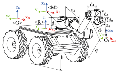
Figure 3 shows the structure of the mobile manipulator. The mathematical model that describes the movement of the mobile manipulator is presented in [37], and the state variables ( x ˙ e e , y ˙ e e łand z ˙ e e ) are related to the control inputs as follows.
x ˙ e e y ˙ e e z ˙ e e T = J μ ω θ ˙ 1 θ ˙ 2 θ ˙ 3 θ ˙ 4 θ ˙ 5 θ ˙ 6 T
where the kinematic function is differentiable, and its differential is the Jacobian matrix J mathematically defined as:
J = h e e f x , y , ψ , θ 1 , θ 2 , θ 3 , θ 4 , θ 5 , θ 6 ,
and h e e = [ x e e y e e z e e ] T is the global position of the end-effector, [ θ 1 θ 2 θ 3 θ 4 θ 5 θ 6 ] T are its joint angles; x, y and ψ are the position and angle of rotation of the mobile platform, respectively. Furthermore, θ ˙ 1 , θ ˙ 2 , θ ˙ 3 , θ ˙ 4 , θ ˙ 5 , θ ˙ 6 are angular velocities of the joints; [ x ˙ e e y ˙ e e z ˙ e e ] T is the velocity of the end-effector; μ and ω are the linear and angular velocities of the mobile platform. Finally, angles and velocities are referenced according to a global reference frame < G > , < M > represent the local coordinate of the robotic arm UR5, and < R > is the local coordinate of the mobile platform. The robotic arm links are represented by d 1 , a 2 , a 3 , d 4 , d 5 and d 6 , the length of the nozzle is represented by d g , a g and the height of the mobile platform is h 1 . Table 3 summarises the values for the link lengths, print nozzle size and mobile platform height.

2.3. Modelling the Environment

2.3.1. Workspace of Mobile Manipulator

The volume of the workspace is an important parameter to evaluate the accessibility of the mobile manipulator [38]. In this study, the Monte Carlo method was applied to analyse the workspace in construction sites; we created a vector of N random values uniformly distributed between 0 and 1. Then, we determined the maximum and minimum angle values for each joint and generated a point cloud with the end-effector positions. The obtained workspace has a spherical shape limited by the joints of the robotic platform, kinematic singularities and dimensions of the links [39,40].
Table 4 shows the parameters of the workspace analysis that allows setting the desired rotation limits for each joint of the manipulator together with the linear and angular velocities of the mobile robot, providing a priori knowledge of the maximum and minimum values required by the robotic platform. The values obtained are used in this work as operating constraints of the mobile manipulator during the 3D printing process of the building elements.

2.3.2. Obstacle Avoidance

The main idea is that the mobile manipulator can develop the 3D printing task through trajectory tracking control while avoiding obstacles. The concept of potential fields allows obtaining the angular and longitudinal velocity of the mobile platform [34]. Then, a distance function to avoid collision between links and mobile platform with the manipulator is defined. In this regard, we consider h e e d as the desired trajectory defined by the building elements; h r o b represents the x , y position of the mobile platform, and h o b s is the position of objects in the plane x , y of the construction site.
U h e e d , h r o b , h o b s = U a t t r h e e d , h r o b + U r e p h r o b , h o b s
We generated a rejection vector to avoid collision between objects and the mobile manipulator in the construction sites. In Equation (3) U a t t r is the target position that produces an attractive force for the end-effector, and U r e p represents the repulsive forces for the parts of the mobile manipulator. U a t t r h e e d , h r o b depends on the robot configuration and the desired trajectory and U r e p h r o b , h o b s represents the repulsive force between the mobile platform and the obstacles on the construction site.
The attractive function defined in Equation (4) allows for achieving the 3D printing of the proposed building elements through a quadratic function of distance that relates the printing profile and the mobile platform.
U a t t r h e e d , h r o b = 1 2 ξ h e e d d 2 h e e d , h r o b
The proposed potential repulsion field (see Equation (5)) creates a barrier around obstacles to ensure that the mobile manipulator does not crash. Therefore, the mobile manipulator motion is not affected if the repulsive potential field is far enough away from the obstacles.
U r e p h r o b , h o b s = 0 i f Q i n f d h r o b , h o b s ξ r 1 d h r o b , h o b s 1 Q i n f i f Q m i n d h r o b , h o b s Q i n f ξ r 1 Q m i n 1 Q i n f i f d h r o b , h o b s Q m i n
where Q i n f is the distance from the obstacle that does not influence the mobile manipulator, Q m i n represents the minimum safety distance between the obstacle and ξ r is the change of the repulsive function.
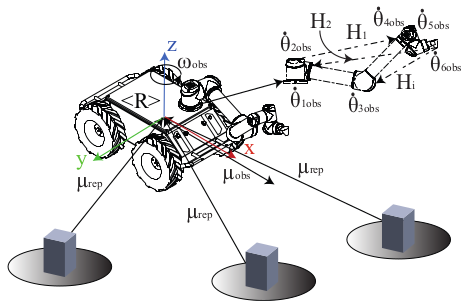
The generated variables modify the linear μ o b s and angular ω o b s velocity for the mobile platform. The manipulator control variables consider the collision distance between the links and the mobile platform with the robotic arm. θ ˙ o b s = θ ˙ 1 o b s θ ˙ 2 o b s θ ˙ 3 o b s θ ˙ 4 o b s θ ˙ 5 o b s θ ˙ 6 o b s represents the control variables modified by collision avoidance, O e is the position of the end-effector, and the centre of the robot platform is < R > , as shown in Figure 4.
We define a distance function H i ( i = 1 , 2 , , n ) to capture the relationship between the mobile platform and the manipulator links. Then, H is defined as the minimum distance described by each link length. However, this distance may change due to the combination of links. In Equation (6), H represents the weighted sum of the minimum distances ( d m i n ) between links. The analysis considers two collision avoidance conditions: (i) between manipulator links d l i n k s and (ii) between the manipulator and the mobile platform d l m .
H = i = 1 n β i d l i n k s i + γ i d l m i
where β and γ are the weights:
β = δ d l i n k s d m i n , 0 < δ < 1 γ = δ d l m d m i n
The value of the weights is a function of the collision distance. The smaller the collision distance, the greater the weight. Δ H is the gradient of H, and we compute its gradient through the partial derivative of H to the i t h joint angle by a discrete difference expressed in Equation (7).
Δ H i = H θ = H θ i + θ i H θ i θ i , i = 1 , 2 , , n ,
where the constant δ θ i is obtained empirically, and the avoidance strategy is a combination of the potential fields described in Equation (5) and the distance criterion defined in Equation (6).

2.4. Motion Control

This work describes the trajectory tracking control strategy for the mobile manipulator to ensure the 3D printing of building elements. For this purpose, a starting point position control is implemented together with a trajectory tracking algorithm. These controllers guarantee the 3D printing task.

2.4.1. Point Stabilization

Driving the mobile manipulator from the current position to the desired starting position is a challenge. This problem involves controlling the velocity of the robot and the end-effector position. For this purpose, a fifth-order function is generated from the current position to the desired position. In this way, this polynomial allows generating a smooth trajectory as an initial condition that allows a slow positioning of the end-effector without producing an abrupt change in the manipulator joints and velocities of the mobile platform.
X p s = a 6 t 5 + a 5 t 4 + a 4 t 3 + a 3 t 2 + a 2 t + a 1 c
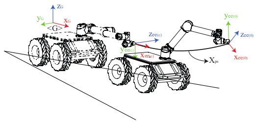
Figure 5 shows the generated trajectory X p s , which is based on the actual position of the end-effector described by x e e c y e e c z e e c T , the initial position of the desired trajectory defined by x e e d 0 y e e d 0 z e e d 0 T and the angular velocity of the mobile manipulator, parameters used to obtain the coefficients of the polynomial.

2.4.2. Trajectory Tracking

The kinematic model proposed in Section 2.2 is used to describe the behaviour of mobile manipulator. This model is based on linear and angular velocities to represent the position of the end-effector. We consider a typical trajectory tracking task with a reference guidance trajectory h e e d = [ x e e d y e e d z e e d ] T , where x e e d , y e e d and z e e d are the desired position of the end-effector. The control of the mobile manipulator is a function of the trajectory tracking error expressed as e = h e e d h e e and the control signals are defined by U n = [ μ ω θ ˙ 1 θ ˙ 2 θ ˙ 3 θ ˙ 4 θ ˙ 5 θ ˙ 6 ] T . Equation (9) presents the kinematic model of the mobile manipulator expressed in discrete time.
x e e n + 1 x e e n T o y e e n + 1 y e e n T o z e e n + 1 z e e n T o = J n U n
The proposed control law is defined by [33]:
U n = J n + x e e d ( n + 1 ) k x x e e d ( n ) x e e ( n ) x e e ( n ) y e e d ( n + 1 ) k y y e e d ( n ) y e e ( n ) y e e ( n ) z e e d ( n + 1 ) k z z e e d ( n ) z e e ( n ) z e e ( n ) + I n J n T J n J n T 1 J n Γ
where the position of the end-effector is defined by the values of h t at discrete time t = n T o , where T o is the sampling period, and n 0 , 1 , 2 , , are denoted as h n = x e e n , y e e n , z e e n T and h n + 1 = x e e n + 1 , y e e n + 1 , z e e n + 1 T , J n + is the Jacobian pseudo-inverse matrix of the mobile manipulator and k x , k y and k z are design parameters to calibrate the controller. Furthermore, the term I n J n T J n J n T 1 J n Γ refers to the self-movement of the mobile manipulator, where the matrix I n J n T J n J n T 1 J n projects onto the null space of the Jacobian manipulator so that the secondary control targets do not interfere with the 3D end-effector printing task. Therefore, any value assigned to Γ affects only the internal structure of the manipulator and does not affect the absolute control of the end-effector. Thus, the redundancy of mobile manipulators can be used effectively to achieve additional performances, such as avoiding obstacles in the workspace, avoiding singular configurations or optimising various performance criteria. Where Γ = μ o b s ω o b s θ ˙ 1 o b s θ ˙ 2 o b s θ ˙ 3 o b s θ ˙ 4 o b s θ ˙ 5 o b s θ ˙ 6 o b s T .

3. Results

The CoopeliaSim simulation software was used to analyse the printing workspace of a mobile manipulator on a construction site [41]. The mobile manipulator used in the simulation consists of a UR5 robotic arm, an end-effector and a mobile platform. The motion constraints and rotation angles of the mobile manipulator were described in Section 2.3.1; these operating parameters were obtained using the Monte Carlo method [38].
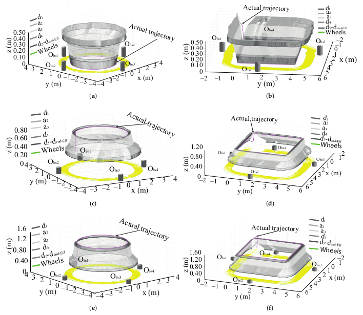
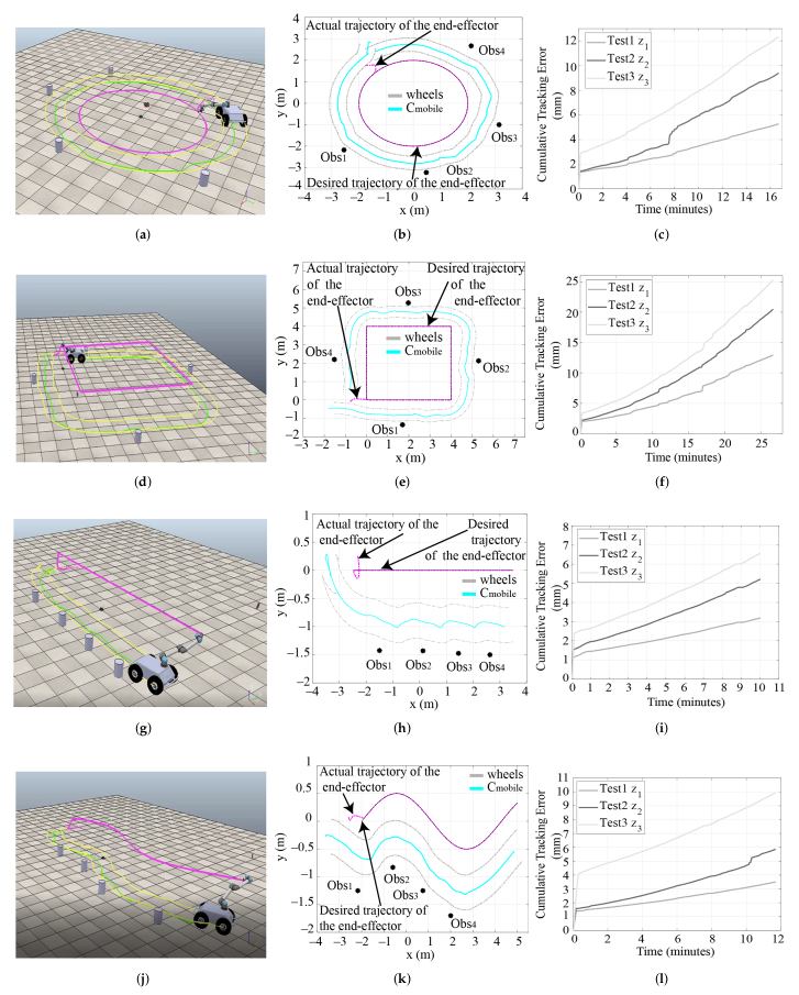
Figure 6 and Figure 7 show the desired trajectory of the end-effector, described by the solid magenta line, while the solid slate grey line corresponds to d 1 . The solid fossil grey line and the cloud grey line represent a 2 and a 3 , respectively. The solid anchor grey line represents d 4 , while the solid pebble grey line represents d 5 to the end-effector. Grey colours of different shades have represented the area of the printing workspace occupied by each manipulator link during the printing of the building elements. Furthermore, we have included the footprint left by the mobile platform as described in the yellow area, and a green dashed line describes the wheels of the mobile platform. The solid grey cubes represent obstacles in the environment.
In order to analyse the printing workspace of the mobile manipulator during the 3D printing task and verify the effect of obstacle avoidance in printing building elements, we design a set of experiments. The first experiment is the avoidance of obstacles located in random positions of the construction site and analysis of the workspace of the mobile manipulator while performing a 3D printing task. The first column of Figure 6 shows the experiments with a circular building element at different heights ( z 1 = 0 m, z 2 = 0.85 m and z 3 = 1.2 m). Tests show that obstacle avoidance does not affect the shape of the workspace. The avoidance action produces a change in the movement of the mobile platform without affecting the movements of the manipulator.
The second experiment consists of printing a square building element, as shown in the second column of Figure 6. The size of the profile is length = 2 m and width = 2 m and consists of three heights ( z 1 = 0 m, z 2 = 0.85 m and z 3 = 1.2 m). The obstacles were distributed as follows: two obstacles near the corner of the initial point, and the other two obstacles were placed two metres away from the corners. In these tests, obstacle avoidance produces a change in the displacement of the mobile platform and the manipulator’s rotation angles. For this reason, it can be seen that the square envelope of the printing workspace varies in shape. However, for the test with z 3 , the movement changes were less significant because the mobile manipulator is closer to the printing profile than to the obstacles.
The first column of Figure 7 shows the printing of a straight profile of 6 m in length. The obstacles have been arranged in a straight line and considering a distance between obstacles. The distance between the first obstacle and the second obstacle is 1.6 m; the second obstacle is 1.3 m away from the third obstacle, and finally, the third obstacle has a distance of 1.1 m from the fourth obstacle. In this third experiment, we considered three printing heights of the building element. The printing workspace shows a sinusoidal shape during 3D printing due to the obstacle avoidance action. The obtained results showed that obstacle avoidance changes the shape of the mobile manipulator’s printing workspace and the displacement behaviour of the mobile manipulator. Based on these observations, we noticed that the mobile platform first evades the obstacle in this profile and then maintains its position while the manipulator moves forward in 3D printing.
The fourth experiment shows the workspace of the sinusoidal profile printing, as shown in the second column of Figure 7. The size of the profile is 7 m. We distributed the obstacles in a sinusoidal line with the following distances between obstacles: the first obstacle is 1.6 m away from the second obstacle, the second obstacle is 1.4 m away from the third obstacle, and finally, the third obstacle has a distance of 1.3 m from the fourth obstacle.
For the sinusoidal building element, the shape of the printing workspace is also sinusoidal. For printing profile heights z 1 and z 2 , the mobile platform first avoids the obstacle and then maintains its position as the manipulator advances in 3D printing. For height z 3 , obstacle avoidance produces changes in the displacement of the mobile platform without affecting the sinusoidal shape of the printing workspace.
The first column of Figure 8 shows the simulation environment with obstacles of the mobile manipulator in the CoopeliaSim software. The second column shows the four proposed printing profiles. The grey dashed line represents the displacement of the wheels of the mobile platform, and the solid cyan line describes the displacement of the centre. The black circle represents the obstacles. The magenta dashed line represents the current trajectory, and the solid black line is the reference trajectory.
The results of the cumulative errors can be seen in Figure 8. Height z 3 registered the highest cumulative error, then z 2 and finally z 1 , as shown in Figure 8c. The error increases as the height of the printing profile increases. In addition, when the height increases, the robotic platform performs a sharp displacement that affects the printing error, which decreases due to the control action described in Section 2.4.2.
The combination of height increase and obstacle avoidance action generates an increase in cumulative error. For example, Figure 8f shows that z 3 had the highest cumulative error compared to z 1 and z 2 . Furthermore, this test recorded the highest cumulative error of all tests. The action of the potential fields causes a change in the behaviour of the mobile platform when it has an object nearby, resulting in changes in the displacement of the mobile platform.
Figure 8i shows the cumulative error for the straight building element. The height z 3 has the highest cumulative error compared to the heights z 1 and z 2 . The sinusoidal displacement of the mobile manipulator due to the obstacle avoidance action produced by the potential field method and the height variation of the printed building element generates an increase in the cumulative error due to the action implemented by the distance function described in Section 2.4.2.
Figure 8l shows that the highest cumulative error occurs at z 3 compared to z 1 and z 2 . The cumulative error increases due to the action of the potential fields, which causes variations in the displacement of the mobile platform when an object is detected. In addition, the increase in the cumulative error is a consequence of the action of the distance function that restricts the movement of the joints when detecting changes in the height of the printed construction elements.

4. Discussion

In this article, we propose an analysis of the printing workspace of a mobile manipulator on the construction site with obstacles during the 3D printing task. The analysis of the results shows that the shape of the workspace varies according to the proposed construction element. Analysis of the mobile manipulator workspace is essential on construction sites to determine the accessibility and mobility of the robotic platform and to identify its limitations according to the size of the mobile manipulator. To study the workspace of the mobile manipulator, we propose an algorithm based on kinematic modelling that optimises the movement of the robotic platform and considers constraints such as obstacle avoidance, the collision between manipulator links and the collision between the mobile platform with the robotic arm.
The printing workspace of the mobile manipulator is an envelope similar to the shape of the proposed construction element. We also noticed that the surface covers the workspace of the mobile manipulator changes in shape as it evades obstacles during 3D printing. Furthermore, we observed that when the height of the building elements varies, the error increases. However, the error of less than 10 mm is still tolerable for 3D printing on construction sites.
Furthermore, it became apparent that the efficiency of the printing process of the building elements depends not only on the obstacle avoidance action of the mobile manipulator but also on the distance between the obstacles with the desired building element profiles.

5. Conclusions

We presented an analysis of the printing workspace of a mobile manipulator in 3D printing applications on a construction site with obstacles. The study uses two widely known concepts in robotic technology: the Monte Carlo method and trajectory tracking control. The Monte Carlo method allowed defining the rotation constraint of each joint of the mobile manipulator and established a priori knowledge of its limitations. As a case study, we present four printing profiles (circular, square, straight and sinusoidal), representing the geometry of building elements in the construction industry performed by robots. To guarantee 3D printing, we controlled the position of the end-effector through a linear algebra controller. In addition, we analysed the workspace based on potential fields and distance function; these methods allowed solving constraints associated with possible collisions between mobile manipulator and obstacles, mobile platform and manipulator, and mobile manipulator and the printed building element.
The results show the relevance of the mobile manipulator in construction, especially for large building elements and low heights, even if they are in variable environments and with obstacles (which is very common in building and infrastructure). Furthermore, these results demonstrate the adaptability of the mobile manipulator to different displacements while maintaining the regularity of the printing task within a suitable tolerance range. However, the printing workspace shape varies with the presence of obstacles affecting the displacement of the mobile platform without affecting the 3D printing of the profile. In addition, the printing error is affected as the height of the printing profile increases. Therefore, it has been determined that the parameters necessary to perform the analysis of the printing workspace are: the type of printing profile, the distance between the mobile platform and the obstacles, the minimum distance between the mobile platform with the desired printing profile and the maximum distance between the desired trajectory and the obstacles. The future research aims to implement printing workspace analysis in an in situ construction considering the terrain, dynamic obstacles, and complex building elements.

Author Contributions

Conceptualization: All authors; The research was performed under the supervision of F.A.C. Literature Review: R.G.R., F.A.C., R.G.A. and A.M.-R. Research Method: R.G.R. and F.A.C.; Software: R.G.R. Drafting the article based on the results: R.G.R. and F.A.C. Reviewed the paper R.G.A. and A.M.-R. All authors have read and agreed to the published version of the manuscript.

Funding

This research was funded by ANID (ex CONICYT) FONDECYT 1181015, the Advanced Center of Electrical and Electronic Engineering AC3E ANID FB008, DGIIP-UTFSM Chile, and the 6th Own Research and Knowledge Transfer Plan of the University of Seville (VI PPIT-US).

Institutional Review Board Statement

Not applicable.

Informed Consent Statement

Not applicable.

Data Availability Statement

Not applicable.

Acknowledgments

The authors would like to acknowledge FONDECYT 1181015 and the Advanced Center of Electrical and Electronic Engineering AC3E ANID FB0008, DGIIP-UTFSM Chile.

Conflicts of Interest

The authors declare no conflict of interest.

References

  1. Parhi, R. A review of three-dimensional printing for pharmaceutical applications: Quality control, risk assessment and future perspectives. J. Drug Deliv. Sci. Technol. 2021, 64, 102571. [Google Scholar] [CrossRef]
  2. Daminabo, S.; Goel, S.; Grammatikos, S.; Nezhad, H.; Thakur, V.K. Fused deposition modeling-based additive manufacturing (3D printing): Techniques for polymer material systems. Mater. Today Chem. 2020, 16, 100248. [Google Scholar] [CrossRef]
  3. Furet, B.; Poullain, P.; Garnier, S. 3D printing for construction based on a complex wall of polymer-foam and concrete. Addit. Manuf. 2019, 28, 58–64. [Google Scholar] [CrossRef]
  4. Paul, S.C.; Tay, Y.W.D.; Panda, B.; Tan, M.J. Fresh and hardened properties of 3D printable cementitious materials for building and construction. Arch. Civ. Mech. Eng. 2018, 18, 311–319. [Google Scholar] [CrossRef]
  5. Aggarwal, L. Reconfigurable Validation Model for Identifying Kinematic Singularities and Reach Conditions for Articulated Robots and Machine Tools. Master’s Thesis, University of Windsor, Windsor, ON, Canada, 2014. [Google Scholar]
  6. Alebooyeh, M.; Urbanic, R.J. Neural Network Model for Identifying Workspace, Forward and Inverse Kinematics of the 7-DOF YuMi 14000 ABB Collaborative Robot. IFAC-PapersOnLine 2019, 52, 176–181. [Google Scholar] [CrossRef]
  7. Panda, S.; Mishra, D.; Biswal, B.; Choudhury, B. An appropriate formulation for workspace cross section area of 3R robot manipulator. In Proceedings of the 2009 International Conference on Industrial and Information Systems (ICIIS), Peradeniya, Sri Lanka, 28–31 December 2009; pp. 511–515. [Google Scholar]
  8. Aboulissane, B.; El Haiek, D.; El Bakkali, L.; El Bahaoui, J. On The Workspace Optimization of Parallel Robots Based on CAD Approach. Procedia Manuf. 2019, 32, 1085–1092. [Google Scholar] [CrossRef]
  9. Hu, B.; Cui, H.; Shi, D.; Zhang, D.; Wang, A.; Wang, Y.; Zhang, Q. Reachable workspace determination for a spatial hyper-redundant manipulator formed by several parallel manipulators. J. Mech. Sci. Technol. 2019, 33, 869–877. [Google Scholar] [CrossRef]
  10. Mahmoodi, M.; Tabrizi, M.G.; Alipour, K. A new approach for Kinematics-based design of 3-RRR delta robots with a specified workspace. In Proceedings of the 2015 AI & Robotics (IRANOPEN), Qazvin, Iran, 12 April 2015; pp. 1–6. [Google Scholar]
  11. Anvari, Z.; Ataei, P.; Masouleh, M.T. Collision-free workspace and kinetostatic performances of a 4-DOF delta parallel robot. J. Braz. Soc. Mech. Sci. Eng. 2019, 41, 99. [Google Scholar] [CrossRef]
  12. Bader, A.M.; Maciejewski, A.A. Maximizing the failure-tolerant workspace area for planar redundant robots. Mech. Mach. Theory 2020, 143, 103635. [Google Scholar] [CrossRef]
  13. Li, Z.Y.; Zhao, D.J.; Zhao, J.S. Structure synthesis and workspace analysis of a telescopic spraying robot. Mech. Mach. Theory 2019, 133, 295–310. [Google Scholar] [CrossRef]
  14. Moulianitis, V.; Xidias, E.; Azariadis, P. Optimal Task Placement in a Metamorphic Manipulator Workspace in the Presence of Obstacles. In Proceedings of the International Conference on Robotics in Alpe-Adria Danube Region, Patras, Greece, 6–8 June 2018; pp. 359–367. [Google Scholar]
  15. Yovchev, K. Iterative learning control for precise trajectory tracking within a constrained workspace. In Proceedings of the International Conference on Robotics in Alpe-Adria Danube Region, Patras, Greece, 6–8 June 2018; pp. 483–492. [Google Scholar]
  16. Ferraguti, F.; Landi, C.T.; Costi, S.; Bonfè, M.; Farsoni, S.; Secchi, C.; Fantuzzi, C. Safety barrier functions and multi-camera tracking for human–robot shared environment. Robot. Auton. Syst. 2020, 124, 103388. [Google Scholar] [CrossRef]
  17. Mohan, C.; Verma, H. Direction and distance sensors and sensing system for elderly people. Mater. Today Proc. 2020, 34, 667–674. [Google Scholar] [CrossRef]
  18. Luu, T.H.; Tran, T.H. 3D vision for mobile robot manipulator on detecting and tracking target. In Proceedings of the 2015 15th International Conference on Control, Automation and Systems (ICCAS), Busan, Korea, 13–16 October 2015; pp. 1560–1565. [Google Scholar]
  19. Safeea, M.; Neto, P.; Bearee, R. On-line collision avoidance for collaborative robot manipulators by adjusting off-line generated paths: An industrial use case. Robot. Auton. Syst. 2019, 119, 278–288. [Google Scholar] [CrossRef] [Green Version]
  20. Goyal, K.; Sethi, D. An analytical method to find workspace of a robotic manipulator. J. Mech. Eng. 2010, 41, 25–30. [Google Scholar] [CrossRef] [Green Version]
  21. Djuric, A.; Urbanic, J.; Filipovic, M.; Kevac, L. Effective work region visualization for serial 6 DOF robots. In Enabling Manufacturing Competitiveness and Economic Sustainability; Springer: Munich, Germany, 2013; pp. 207–212. [Google Scholar]
  22. Urbanic, R.; Gudla, A. Functional Work Space Estimation of a Robot using Forward Kinematics, DH Parameters, and Shape Analyses. In Proceedings of the ASME 2012 11th Biennial Conference on Engineering Systems Design and Analysis, Nantes, France, 2–4 July 2012; pp. 381–391. [Google Scholar]
  23. Liu, Z.; Zhang, R.; Wang, W.; Ma, X.; You, R.; Li, Z. Robot Workspace Reconstructing Solving Method Based on Image Engine. In Proceedings of the 2017 International Conference on Industrial Informatics-Computing Technology, Intelligent Technology, Industrial Information Integration (ICIICII), Wuhan, China, 2–3 December 2017; pp. 181–185. [Google Scholar]
  24. Zaplana, I.; Basanez, L. A novel closed-form solution for the inverse kinematics of redundant manipulators through workspace analysis. Mech. Mach. Theory 2018, 121, 829–843. [Google Scholar] [CrossRef] [Green Version]
  25. Chen, Y.; Zhang, J.; Yang, C.; Niu, B. The workspace mapping with deficient-DOF space for the PUMA 560 robot and its exoskeleton arm by using orthogonal experiment design method. Robot. Comput.-Integr. Manuf. 2007, 23, 478–487. [Google Scholar] [CrossRef]
  26. Jha, R.; Chablat, D.; Baron, L.; Rouillier, F.; Moroz, G. Workspace, joint space and singularities of a family of delta-like robot. Mech. Mach. Theory 2018, 127, 73–95. [Google Scholar] [CrossRef] [Green Version]
  27. Fiore, E.; Giberti, H.; Sbaglia, L. Dimensional synthesis of a 5-DOF parallel kinematic manipulator for a 3d printer. In Proceedings of the 2015 16th International Conference on Research and Education in Mechatronics (REM), Bochum, Germany, 18–20 November 2015; pp. 41–48. [Google Scholar]
  28. Peidró, A.; Reinoso, Ó.; Gil, A.; Marín, J.M.; Payá, L. An improved Monte Carlo method based on Gaussian growth to calculate the workspace of robots. Eng. Appl. Artif. Intell. 2017, 64, 197–207. [Google Scholar] [CrossRef]
  29. Zhang, H.; Zhang, K.; Gao, J. Dynamically Based Motor Parameters for Delta Robots Using the Specified Workspace. In Proceedings of the 2019 IEEE 6th International Conference on Industrial Engineering and Applications (ICIEA), Tokyo, Japan, 12–15 April 2019; pp. 814–818. [Google Scholar]
  30. Zhang, S.; Teizer, J.; Pradhananga, N.; Eastman, C.M. Workforce location tracking to model, visualize and analyze workspace requirements in building information models for construction safety planning. Autom. Constr. 2015, 60, 74–86. [Google Scholar] [CrossRef]
  31. Hosny, A.; Nik-Bakht, M.; Moselhi, O. Workspace planning in construction: Non-deterministic factors. Autom. Constr. 2020, 116, 103222. [Google Scholar] [CrossRef]
  32. Kassem, M.; Dawood, N.; Chavada, R. Construction workspace management within an Industry Foundation Class-Compliant 4D tool. Autom. Constr. 2015, 52, 42–58. [Google Scholar] [CrossRef]
  33. Scaglia, G.; Montoya, L.Q.; Mut, V.; di Sciascio, F. Numerical methods based controller design for mobile robots. Robotica 2009, 27, 269–279. [Google Scholar] [CrossRef] [Green Version]
  34. Wang, W.; Zhu, M.; Wang, X.; He, S.; He, J.; Xu, Z. An improved artificial potential field method of trajectory planning and obstacle avoidance for redundant manipulators. Int. J. Adv. Robot. Syst. 2018, 15, 1729881418799562. [Google Scholar] [CrossRef] [Green Version]
  35. Husky Unmanned Ground Vehicle. Husky UGV—Outdoor Field Research Robot by Clearpath. Available online: https://clearpathrobotics.com/husky-unmanned-ground-vehicle-robot/ (accessed on 12 July 2021).
  36. Universal Robots. Collaborative Robotic Automation|Cobots from Universal Robots. Available online: https://www.universal-robots.com/ (accessed on 12 July 2021).
  37. Rivera, R.G.; García Alvarado, R.; Martínez-Rocamora, A.; Auat Cheein, F. A Comprehensive Performance Evaluation of Different Mobile Manipulators Used as Displaceable 3D Printers of Building Elements for the Construction Industry. Sustainability 2020, 12, 4378. [Google Scholar] [CrossRef]
  38. Yao, J.; Sun, X.; Zhang, S.; Yang, M.; Zhang, X. Monte Carlo method for searching functional workspace of an underwater manipulator. In Proceedings of the 2018 Chinese Control And Decision Conference (CCDC), Shenyang, China, 9–11 June 2018; pp. 6431–6435. [Google Scholar]
  39. Cao, B.; Sun, K.; Gu, Y.; Jin, M.; Liu, H. Workspace Analysis Based on Manipulator Pose Dexterity Map. In Proceedings of the 2018 3rd International Conference on Robotics and Automation Engineering (ICRAE), Guangzhou, China, 17–19 November 2018; pp. 166–170. [Google Scholar]
  40. Liu, Q.; Chen, C.Y.; Wang, C.; Wang, W. Common workspace analysis for a dual-arm robot based on reachability. In Proceedings of the 2017 IEEE International Conference on Cybernetics and Intelligent Systems (CIS) and IEEE Conference on Robotics, Automation and Mechatronics (RAM), Ningbo, China, 19–21 November 2017; pp. 797–802. [Google Scholar]
  41. Coppelia Robotics. Robot Simulator CoppeliaSim: Create, Compose, Simulate, any Robot—Coppelia Robotics. Available online: https://www.coppeliarobotics.com/ (accessed on 12 July 2021).
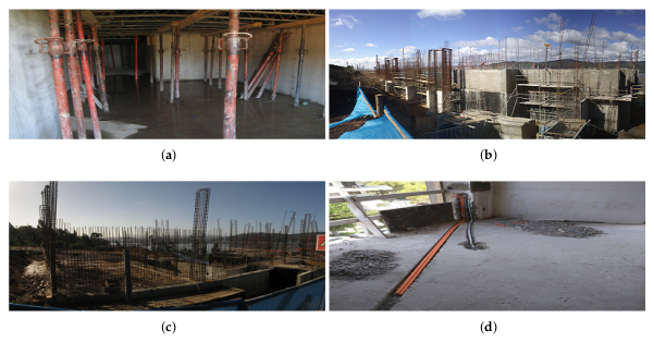
Figure 1. Dynamic environment: construction areas; (a) formwork system, (b) distribution of a formwork system, (c,d) common cracks in construction environments. The images are courtesy of the Department of Design and Theory of Architecture of the University of Bio Bio.
Applsci 11 07923 g001
Figure 2. Workspace analysis of a mobile manipulator in 3D printing task.
Applsci 11 07923 g002
Figure 3. Mobile manipulator model: robotic arm with 6DOFs mounted on mobile platform.
Applsci 11 07923 g003
Figure 4. Mobile manipulator with field potential.
Applsci 11 07923 g004
Figure 5. Stabilization point of the end-effector of the mobile manipulator. The actual position of the end-effector towards the starting point of the desired trajectory.
Applsci 11 07923 g005
Figure 6. The solid magenta line describes the circular and square printing profiles. (af) show the tests carried out for three heights, z 1 , z 2 and z 3 for a circular profile of 2 m radius and a square profile of 2 m width and 2 m length.
Applsci 11 07923 g006
Figure 7. The solid magenta line describes the sinusoidal and straight printing profiles. (af) show the tests carried out for three heights, z 1 , z 2 and z 3 for a sinusoidal profile of 7 m radius and a straight profile of 6 m.
Applsci 11 07923 g007
Figure 8. The trajectory reproduced in CoppeliaSim is shown in the first column (a,d,g,j). The second column (b,e,h,k) shows the four proposed printing profiles. The third column (c,f,i,l) shows the cumulative printing errors for three different heights.
Applsci 11 07923 g008
Table 1. Methods to obtain the optimal workspace for industrial robots.
Industrial PrototypesOptimal Workspace AnalysisReferences
RV-M1 MitsubishiThe model of the optimal workspace of an industrial manipulator is based on the Denavit–Hartenberg parameters.[20]
FANUC crThe workspace is estimated with a window algorithm with singularity visualization for manipulator configuration.[21]
ABB IRB-140The study of the workspace uses the kinematic model and shape analyses.[22]
Robotic armABB IRB-1660IDA visual method is compared with the Monte Carlo method to obtain the optimal workspace of the manipulator robot. The results show that the visual model presents better modeling and digitalization features.[23]
Kuka LWR 4+ Staubli TX90The study analyses the workspace of two redundant robots by discretising some joints and then reconstructs the 3D by revoluting the plane area computed. The advantage of this method is that it calculates the value of the workspace volume, allowing better tracking of the differences between the workspaces.[24]
PUMA 560The technique of mapping the workspace with deficient-DOF solves the problems of maneuverability and stability of the robotic arm.[25]
Delta 3DOFThe algorithm of Cylindrical Algebraic Decomposition is studied to obtain the optimal workspace of the industrial manipulator. The SIROPA library represents the complexity and singularity of the workspace.[26]
Delta 5DOFGenetic algorithms are analyzed to find the optimal workspace.[27]
Parallel RobotDelta 10 DOFThe Monte Carlo method is used along with a Gaussian distribution to evaluate the limits of the optimal workspace.[28]
FANUC-DeltaThe SolidWorks software determines the limits of the robot arm joints. The dynamic simulation function accurately describes the motion of the robot platform in an optimal workspace.[29]
Table 2. Robotic platforms: main features UR5 and Husky.
Robotic PlatformWeightPayloadReachSpeedI/O Power Suply
UR5 (Manipulator)18.4 kg5 kg850 mm π rad/s24 V 2 A
Husky (Mobile platform)50 kg75 kg-1.0 m/s24 V 5 A
Table 3. Parameters of mobile manipulator.
Parameters d 1 a 2 a 3 d 4 d 5 d 6 d g a g h 1
Length (m)0.08920.4250.3920.10930.094750.08230.0050.010.41
Table 4. Analysis of the workspace of a mobile manipulator based on the Monte Carlo method. Upper and lower rotation limits of the mobile manipulator joints.
Robotic Arm θ 1 θ 2 θ 3 θ 4 θ 5 θ 6 Mobile Platform
θ m i n (rad) 2 π 3 π 2 π 2 π 4 π 4 0 μ m i n (m/s) ± 0.1 ω m i n (rad/s) π
θ m a x (rad) 2 π 3 5 π 36 5 π 36 5 π 6 5 π 6 π μ m a x (m/s) ± 0.7 ω m a x (rad/s) π
Publisher’s Note: MDPI stays neutral with regard to jurisdictional claims in published maps and institutional affiliations.