Article

Guidelines for Topology Optimization as Concept Design Tool and Their Application for the Mechanical Design of the Inner Frame to Support an Ancient Bronze Statue

Department of Mechanical and Aerospace Engineering, Sapienza Università di Roma, Via Eudossiana 18, 00184 Rome, Italy
*
Author to whom correspondence should be addressed.
Appl. Sci. 2021, 11(17), 7834; https://doi.org/10.3390/app11177834
Submission received: 30 June 2021 / Revised: 9 August 2021 / Accepted: 18 August 2021 / Published: 25 August 2021
(This article belongs to the Special Issue Design for Additive Manufacturing: Methods and Tools)

Abstract

:
For the past few decades, topology optimization (TO) has been used as a structural design optimization tool. With the passage of time, this kind of usage of TO has been extended to many application fields and branches, thanks to a better understanding of how manufacturing constraints can achieve a practical design solution. In addition, the advent of additive manufacturing and its subsequent advancements have further increased the applications of TO, raising the chance of competitive manufacturing. Design for additive manufacturing has also promoted the adoption of TO as a concept design tool of structural components. Nevertheless, the most frequent applications are related to lightweight design with or without design for assembly. A general approach to integrate TO in concept designs is still missing. This paper aims to close this gap by proposing guidelines to translate design requirements into TO inputs and to include topology and structural concerns at the early stage of design activity. Guidelines have been applied for the concept design of an inner supporting frame of an ancient bronze statue, with several constraints related to different general design requirements, i.e., lightweight design, minimum displacement, and protection of the statue’s structural weak zones to preserve its structural integrity. Starting from the critical analysis of the list of requirements, a set of concepts is defined through the application of TO with different set-ups (loads, boundary conditions, design and non-design space) and ranked by the main requirements. Finally, a validation of the proposed approach is discussed comparing the achieved results with the ones carried out through a standard iterative concept design.

1. Introduction

Topology optimization (TO) naturally gives a wider set of possibilities and a larger degree of freedom with regard to the design space availability, as compared to size and shape optimization. Due to this, TO has been the most widely accepted and well-established structural optimization tool [1]. To improve the performance of TO, passing through a natural process of scientific progress, several approaches have been established, such as the homogenization method [2,3], the SIMP method [4,5], the level set method [6,7], the MMC/MMV method [8,9], and some evolutionary and heuristic methods [10,11,12]. For the last few decades, TO has been implemented effectively as a conceptual design tool to achieve the desired mechanical performance with feasible manufacturing [1,13,14]. The desired mechanical performance is achieved with the help of a specific objective function (e.g., compliance minimization, maximization of fundamental frequency, mass reduction, etc.) and suitable design constraints (e.g., displacement, fatigue, stress, etc.). Similarly, the feasible manufacturing is obtained through several manufacturing constraints (e.g., draw, extrusion, member size, overhang size, symmetry, etc.). Before the advent of additive manufacturing (AM), manufacturing of the topologically optimized designs was challenging task, sometimes not totally achievable, due to complex geometrical features and hidden cavities. Though several manufacturing constraints could have been considered in order to facilitate conventional manufacturing, a process of remodeling of the optimized design was required for achieving a feasible manufacturing. This procedure resulted not only in an increase of the final mass of the piece, but also in an increase of the design processing time. Therefore, the advent of additive manufacturing and its subsequent advancements further increased the applications of topology optimization with regard to a feasible manufacturing of complex geometries without any remodeling (or, in a few cases, with little remodeling operations connected to specific AM constraints).
TO presents numerous remarkable practical applications such as the design of structures with multi-objectives [15], multi-scale [16,17,18] and multi-material [19,20], design of functionally graded structures [21,22], design of energy absorption structures to improve resistance against crash failures [23,24], design of periodic structures to improve stability against buckling failure [25], design of architectural structures [26,27], production of sustainable design [28], etc. Similarly, TO provides several other worthwhile applications in conjunction with other optimization tools such as TO with lattice structures to improve resistance against buckling failure [29,30], and designing efficient heat dissipation structures [31], TO with shape optimization [32,33] for better shape and maximum weight reduction, TO with generative design [34,35] to achieve better structural performance, or with tools able to select design variants for optimizing both product and process features [36], etc. Furthermore, researchers are currently working on TO in order to produce some state-of-the-art designs regarding structures with negative Poisson ratio [37], structures with negative thermal expansion [38], structures with natural convection [39], load-supporting structures for civil engineering [40,41], etc. On the other hand, there are still some open issues evolving around TO. These issues are mainly concerned with the aesthetic problem [42]; additive manufacturing problems related to large overhanging members [43,44,45,46], the remodeling of the optimized structure due to poor shape geometry [47]; stress-related problems [48,49,50]; the application of manufacturing constraints [14]; the optimization of multi-scale and multi-material structures [16,17,18,19,20], etc.
Conceptual design is a fundamental milestone at the initial phase of any product development process, helping the early assessment of optimal design solution with regard to other crucial factors such as manufacturing, time-to-market, performance, testing and cost [1,13,14]. Therefore, the designers always come up with several design solutions in the concept design phase and after a meticulous evaluation, select the best one. According to literature [51,52], around 80% of the product quality/cost ratio can be determined by the end of the initial design phase and therefore, the initial design phase plays a vital role. To bolster the initial design phase, numerous design tools have been developed to expedite the design process. In addition, the latest technological advancements in the field of computer, programming, artificial intelligence, CAD tools (i.e., integrated in many commercial software) and numerical solvers have further enhanced the design process with regard to fast computations and complex simulations [53,54,55]. For the last few decades, topology optimization (TO) has been extensively studied together with generative design (GD) as superior conceptual design methodologies [1,13,14,42,56]. Despite this, TO is usually seen as a specific structural optimization tool instead of a way to define concepts. On the contrary, GD has the advantage of simultaneously considering many materials and manufacturing methods for a single simulation, which reduces the simulation time. In addition, GD provides many design solutions as a combination of different structures and materials in a single simulation, while TO provides a single design solution. Furthermore, TO can implement manufacturing constraints to drive the final shape to a feasible manufacturing, while GD uses manufacturing methods and provides much better optimized shape for manufacturing, and therefore requires little or no remodeling. On the other hand, TO is useful in higher mass reduction and fast computation. However, both TO and GD have numerous applications inside automotive, aerospace, civil, and medical engineering [1,13,14,42,56,57,58,59,60,61].
This paper investigates TO as a concept design tool in mechanical engineering, providing guidelines to assess its input from a list of requirements so that preliminary sketches may be provided. The paper aims to extend its assessment from the methodological point of view to foster its adoption in the creative definition of innovative components, constrained by mechanical criteria, at the early stage of design. In Section 2, the methodological part is provided in terms of mathematical formulation and computational set-up (Section 2.1) of the proposed TO approach, and the design workflow and guidelines (Section 2.2). Then, in Section 3, a case study is provided to show an example of how carrying out the requirements translations into TO input conditions and, in Section 4, results are discussed to compare it with a standard design workflow. Finally, in Section 5, conclusions are outlined.

2. Methods

TO may reduce design efforts to review concepts of the geometrical models of the parts in accordance with the targets defined in the list of requirements. In mechanical design it can also support preliminary assessment of assemblies if proper guidelines are defined to assist the work. In this section, we propose guidelines to apply TO at the early concept design stage, so that, through a proper definition of the geometric domain of the parts/components, effective topologies may be derived while respecting design intents. Since guidelines are usually tailored on specific context, in Section 2.1, the mathematical formulation and computation set-up of the methodology we propose to use are provided. Then, in Section 2.2, the design workflow and guidelines of the proposed approach are described.

2.1. Mathematical Formulation and Computation Set-Up

Density-based topology optimization is formulated through the finite element method (FEM). Element density acts as a design variable, so that an optimal distribution of elements layout may be provided within the chosen design space.
Design space is approximated by a finite element analysis (FEA) mesh. FEA determines the displacement and stress gradients that help TO in the identification of elements that do not affect the optimization problem (mass reduction, compliance minimization, frequency response, etc.). During each iteration, sensitivity analysis is performed by the solver to evaluate the effect of the element density variable on the objective function and, subsequently, the element densities are updated in the design space for the next iteration and the same process is continued until a final convergence is obtained. Mathematically, for convergence, the derivative of the objective function with respect to the design variable, the element density, is studied. Basically, in density-based TO, the elements are assigned a density value from 0 to 1, where 0 represents a void, 1 represents a solid and values from 0 to 1 represent intermediate densities. In order to enforce the solution to the solids and voids discrete combination, density-based TO exploits the SIMP (solid isotropic material penalization) approach to eliminate the elements with intermediate densities with the help of power law (as shown below):
k i = ( ρ i ) P k o
where “i” is the number of elements in the design space, i = 1, 2, 3, …, L; “ρi” is the density of the ith element, “P” is the penalization factor in the range 1 < P ≤ 3; “k0” and “ki” are the stiffnesses of ith element before and after penalization, respectively. TO with SIMP approach has been declared the most implemented and developed approach with respect to math simplicity and computational efficiency. As per numerical experimentations, a penalty factor of value 3 has been found the most suitable one for penalization purpose.
Distinction between design and non-design space allows an easy set-up of the conceptual geometric domain, assuming as non-design space regions constrained by functional interfaces (e.g., displacement constraints, contact surfaces, other assigned boundary conditions). The optimization problem solved by SIMP is a minimization problem related to design space volume fraction or compliance ( C ) , or in another words, maximization of the stiffness of the structure that can be defined for the overall domain or only for the design space. According to compliance theory, compliance is inversely proportional to the stiffness of the structure. The global compliance is the sum of the element’s elastic characteristics or strain energies (as shown below).
C = 1 2 F U T = 1 2 i = 1 L f i   u i T
where “ F ” is the external load vector, “ U ” is the global displacement vector and “L” is the overall number of finite elements.
According to Hook’s Law F = KU, therefore C = 1 2 F 2 K 1 hence 1 2 and F are constants, therefore C   α   K 1 where K is the global stiffness matrix. Using the SIMP approach K is computed as:
K = i = 1 L k i = i = 1 L ( ρ i ) P k o
where ρ i is in the range η ρ i 1 and i = 1 ,   2 ,   3 , L ; and η is a very small number but greater than zero to prevent the global matrix from being singular and so ensure the FEA stability.
Different constraints may be set (e.g., mass, load, displacement in specific ranges) and also weighted customized objective functions may be defined. Similarly, TO may be subjected to manufacturing constraints to achieve feasible manufacturing shapes (e.g., direction of protrusion, forging shapes, etc.) [1]. From Equation (2), the general formulation of SIMP for the compliance minimization problem becomes:
M i n i m i z e   C = 1 2 i = 1 L f i   u i T = 1 2 i = 1 L f i 2 ( ( ρ i ) P k o ) 1
Subject   to :
1.
F = K U ;   To   ensure   static   equilibrium ;
2.
G = j = 1 M g j 0 ;   Design   Constraints ,   j = 1 , 2 , , M ;
3.
H = k = 1 N h k 0 ;   Manufacturing   Constraints ,   k = 1 , 2 , , N ;
4.
η ρ i 1 and i = 1 , 2 , 3 , L .
The above objective function is used for a single loadstep. When multiple loadsteps occur, the minimization is carried out on the weighted compliance ( W c ), defined as:
M i n i m i z e   ( W c ) = q = 1 R W q   C q T = 1 2 q = 1 R W q   f q   u q T
where “Wq” is the specific weight of each loadstep, “Cq” is the compliance of individual loadstep and “R” is the overall number of total loadsteps.

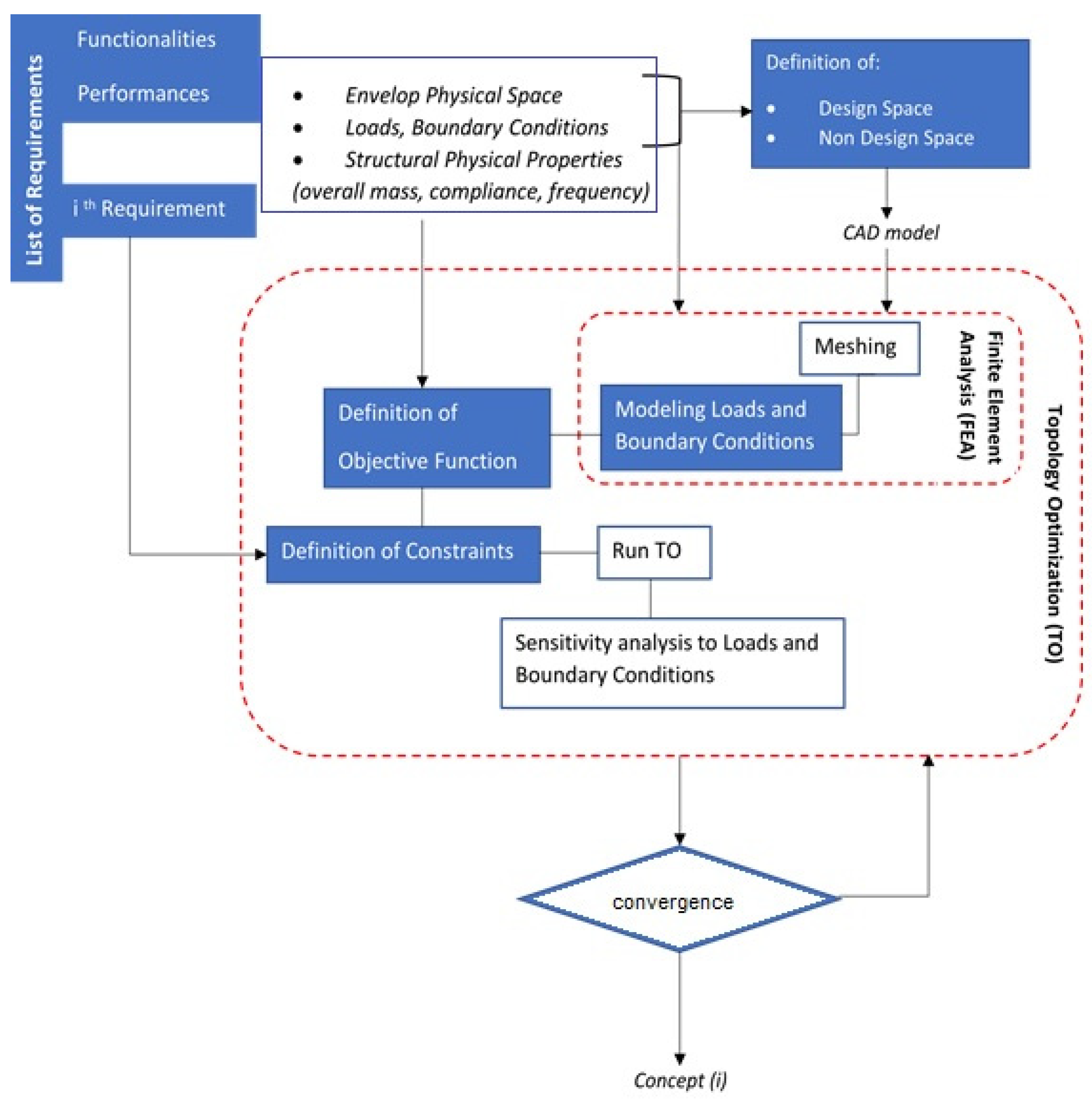
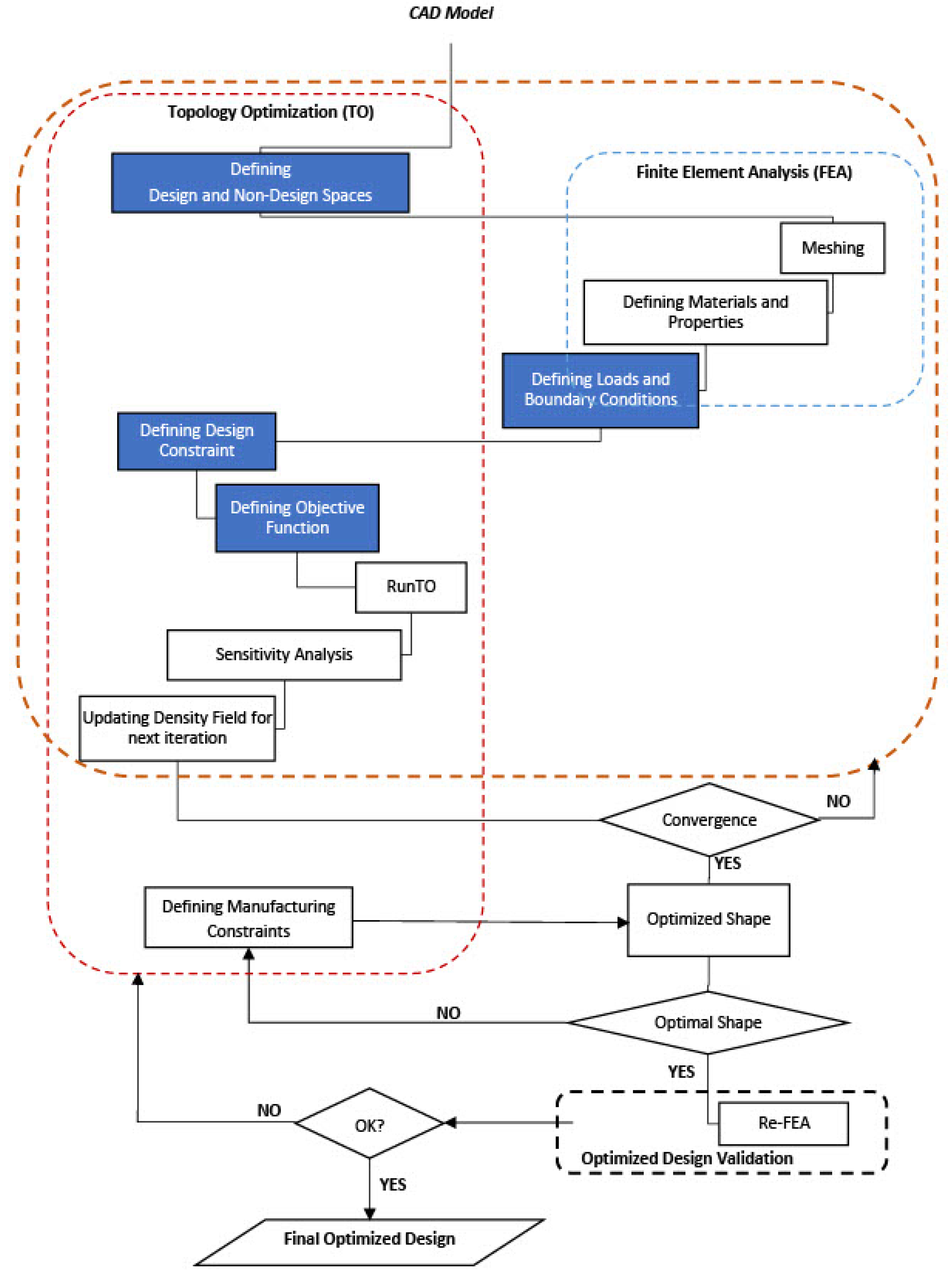
2.2. Design Workflow and Guidelines

Common applications of TO start from the CAD model of the preliminary design of the component. Here, its approach is discussed to foster innovative geometric parts with respect to mechanical targets that may derive from the list of requirements defined for mechanical engineering design.
A standard TO process is performed according to Figure 1. As an optimization step during preliminary or executive design, its definition is strongly connected to a preliminary CAD model of the component and to the FEA modeling accuracy. To gain the proper accuracy, material properties and physical approximation of load conditions must be properly defined (e.g., contact friction and/or constraints compliance if present). Manufacturing constraints are not included directly in the optimization loop, under the assumption that during TO, the designer is also looking for disruptive solutions (despite the manufacturing constraints). Nevertheless, in accordance with an integrated product-process approach, manufacturing constraints may collapse in the design constraints step.
In concept design, the final CAD model of the component/structure must be the output of the workflow, not the input. The input model of the TO must represent a CAD of the design and non-design space. Design space may be the maximum lengths possible with the subtraction of volumes and areas that are functional interfaces for loads and boundary conditions (displacements, fluxes, velocity, etc.). Design and non-design spaces are defined as enveloping defeatured volumes avoiding any influence given by designers’ choices [14]. Through these considerations, the modified workflow is proposed in Figure 2.
In this case, the preliminary FEA step has the role of helping the translation of the performances into TO inputs (mainly loads and boundary constraints). From this, basic guidelines that may provide benefits to the concept design workflow are:
  • a set of requirements (e.g., aesthetics, ergonomics, transportability, etc.) may constrain the final envelop of the shapes. The definition of design and non-design spaces operatively forces this kind of evaluation, which can be multi-criteria (thus taking into account together many requirements) or not. In this case, requirements may help to define geometrical variants in terms of design space.
  • The need for simulating the structural behaviour of the system by FEA requires an anticipated evaluation of the target values, enforcing the physical feasibility of the concept evaluation.
  • Looking for optimal topology in assemblies, a clear model of the operative conditions must be defined, so that a preliminary understanding of the worst kinematic/dynamic conditions can be defined. Envelop volumes coupled with multibody analysis such as the equivalent static load method may help the assessing of the problems of flexible multibody assemblies [62].
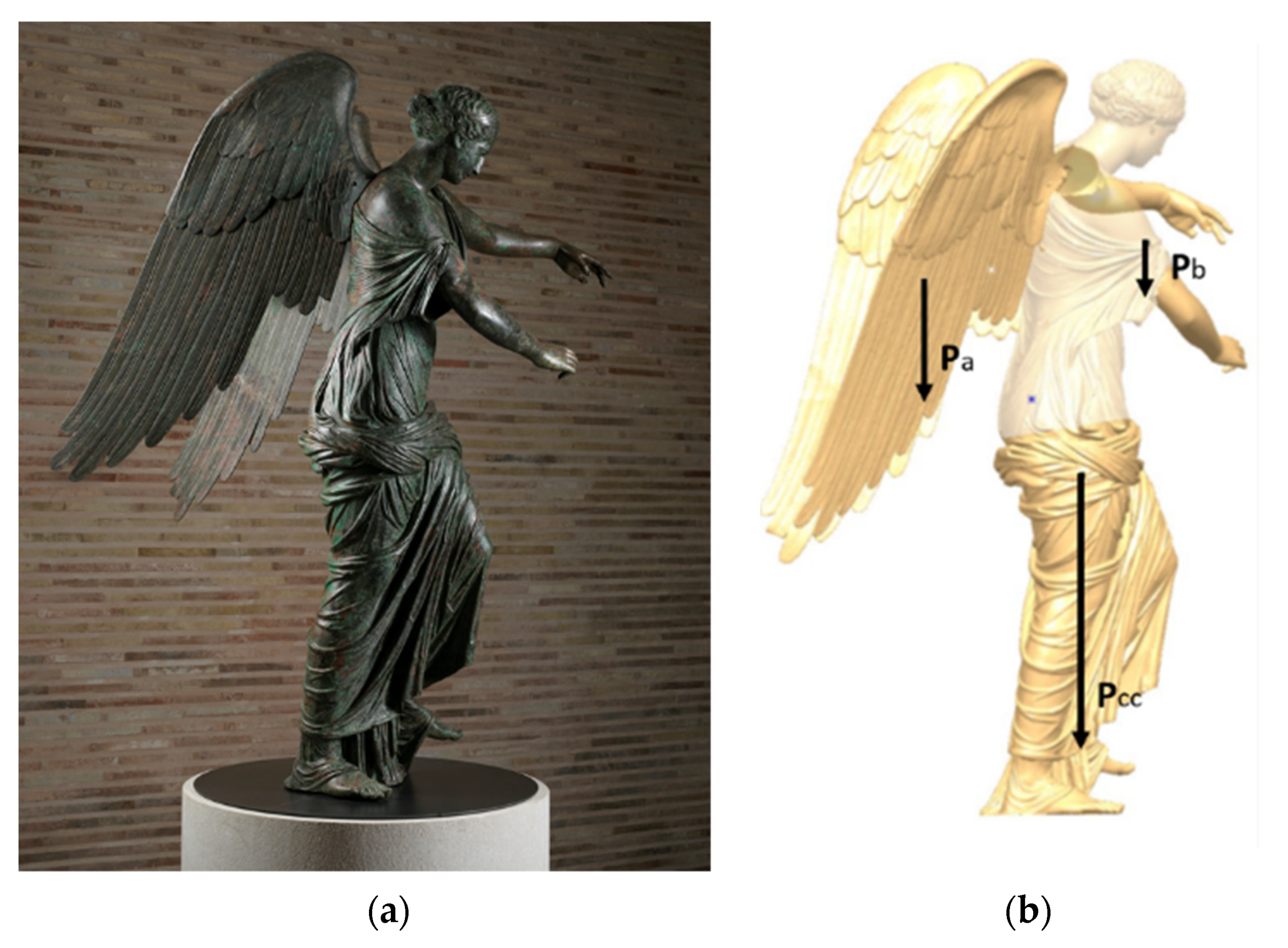
3. Case Study

The case study concerns the application of TO as a concept design tool for an inner frame of a virtually approximated model of an ancient bronze statue named Vittoria Alata. It explores how to obtain TO optimization requirements from general design requirements (DR) and how to derive design and non-design Space (DS and NDS) and, through them, obtain concepts.
The original statue was recently restored and moved to a new exhibition space in the ancient Capitolium of Brescia (Italy). Restoration also included a new inner frame, described in [63]. The present application assumes the requirements assessed in [63] as the starting point of the concept design with TO and the actual result with its standard design workflow as a reference for its validation.
The statue is composed of 5 parts: a central body, left and right arm, left and right wings (Figure 3).
In Figure 3b, the Pa, Pb, and Pcc are describing the effect of the loads as concentrated masses of the wings, arms, and central body at their respective COGs (center of gravity).

3.1. Design Requirements and the Definition of Design Space and Non-Design Space

Requirements of the design problem [63] are summarized in Table 1, both as design requirements (DR) and topological optimization requirements (OR).
The maximum envelope of the DS is the volume inside the statue, without taking into account the head, which is considered bulk (during the restoration process, the ancient filling has been removed except for the head filling, judged able to be safely maintained). DS is the volume where the inner frame can be placed. The statue itself represents part of the non-design space where loads act (the weight of central body, wings, and arms) and where interfaces between the inner frame and bronze are possible. Non-design space has been modeled starting from a 3D acquisition of the outer surface of the statue, made by structured light. Non-design space also includes the connection interface with the ground as prescribed by DR6 (→OR6.1) and a central volume preliminary assumed as a circular beam to accomplish DR4 and 5 (→OR4.1 and 5.1). The central beam’s orientation is constrained by the smallest section, highlighted in Figure 4a as S1, and by the necessity of correct alignment during assembly, since it will be the first element to be inserted during the mounting procedure. Its position can be defined using a pocket already present in the inner filling of the head (the only ancient filling maintained) and other reference contacts at the opposite side (e.g., at Sa or S1 of Figure 4a).
These reasonings, deduced as target values of DR4, DR5, and DR8, define the functional role of the central beam as part of the non-design space (NDS) and fix its position and section length. Solidity, as derived in OR6.2, asks for constrained sections; that means that they must move together without relative rotation in respect to the inner frame along the horizontal plane. Figure 4a shows where these sections may be localized due to the accessibility for assembly (Sa, Sb, and Sc of Figure 4a).
Minimum condition suggests highlighting three points for Sa and Sc that may be contact points with the statue. Sb has been introduced as a contrast point with the statue with respect to contact at the leg. BCs at Sa are defined on the central beam, to simulate the connection with the base. In these points, boundary constraints (BCs) are defined to lock relative motion among DS and NDS as shown in Figure 4b. BCs are also selected to reproduce the support scheme on the left leg and right shoulder. This means locking the DOF in z direction at the center of the thigh and shoulder, as depicted by P1 and P2 in Figure 4b.

3.2. Design Requirements and the Definition of Boundary Constraints and Load Conditions

Load conditions, to be applied, are stress-strain conditions derived from the static analysis of the central body and the effects due to the assembly of arms and wings on the inner frame, as described in Figure 3b. Wings and arms introduce a bending moment in the lateral plane of the statue that passes through its left knee (P1 in Figure 4a). From the design requirements point of view, the central body stress must be maintained in the same conditions as before the restoration, characterized by the presence of a filling of resin able to minimize relative rotation between the inner frame and the statue. This filling has been removed for material preservation requirements, hence the necessity of a new inner frame. To define the worst reference condition derived from the filling removal, a preliminary FEA on the central body was done. Figure 4c shows von Mises equivalent stress superimposed to the magnified plot of the relative displacements from the undeformed shape (grey mesh), as derived from the gravity load, without imposing any filling inside. The gravity load of the central body defines a bending effect, in the frontal plane, that overstresses the base of the neck, where a visible crack is present. This defines a major constraint on the compliance of the structure that must reduce the final displacement of the head (OR2.1, 2.2 and 3.1). Areas useful for suspending the central body with a simple contact interface are the left leg (above the knee) and the right shoulder (P2 and P1 in Figure 4a,b). These have been derived after a deep phase of material analysis, with several specialists involved (chemists, physicists, restorers, engineers); only these areas have been validated as stiff and safe enough to be used for support interfaces, according to DR1 that determines OR1.2: “Avoid interfaces on thin or weak areas”. According to OR1.1, maximum equivalent stress at the contact interface must be at least half the value of 80 MPa, considering a safety factor equal to 2. This value is consistent with the aim of achieving a final condition able to preserve ancient material, assuming its yielding value in the range of [80 ÷ 150] MPa.

3.3. Topological Optimization Set-Up

As previously described, the first guess concept assumes, as design space (DS), a bulk 3D filling of the statue, surrounding the central beam from the feet up to the base of the neck. Equivalent loads of the central body are applied at the bottom of the central beam. Rigid links are used to transfer force and moment. Table 2 summarizes design intent in terms of TO problem set-up and numerical constraints as derived by the DRs.
The first guess concept minimizes compliance of the design space, looking for a volume fraction of the DS less than 0.1. The adoption of this extreme threshold derives from the assembly requirements DR8 and OR8.2, which highlight a wireframe structure as preferred.
For what concerns TO solver options, using Optistruct, we set up the usage of SIMP approach with a dual optimization algorithm for achieving convergence, in addition to any limit in terms of minimum member size. This choice represents an advisable set-up for concept level optimization, especially when many design variables are involved.

4. Results and Discussion

Load effects on the final structure were investigated as single effects of central body, wings and arms (designated CB, W, and A, respectively) and overall load, so that their single and interaction effects on the final topology of the concepts may be seen. The presence of BC at Sa has been highlighted through the code Sa. The sensitivity to its effect has been introduced to understand its relevance in the final reaction, considering that it may be redundant to S1.
Figure 5, Figure 6, Figure 7 and Figure 8 show an overall view of the results in terms of density distribution. Red areas represent density equal to 1. Admissible domains are in the range of 0.5 ÷ 1. They are shown in back and front view to highlight the distribution of density (on the left of each figure). On the right of the figures, the final material distribution is highlighted by section cuts (in blue), made along two concurrent/intersecting planes that pass through the central beam and P1 and P2, respectively. Doing so, the loading path between the interface with statue and the central beam may be seen.
CB case shows that load is well supported by areas around P1 and P2 as shown by the section cuts of the related cases, reported in Figure 5b and Figure 6b. As reported in Figure 5 and Figure 6, the massive part of the optimized resulting structure is connected to the central beam at the hip height, slightly upwards of the position of the original center of mass of the CB.
In the CBWA case, this bulk part is reduced. The left leg increases its relevance due to the wings, which produce bending tension along the plane passing in P2. Due to this occurrence, the role of the area around the shoulder becomes less relevant with respect to the CB load case (as reported in Figure 7 and Figure 8).
Loadcase CBWA_Sa (Figure 8) reveals that the adoption of the in-plane BC at Sa avoids mass concentration at the bottom. The major problem of this solution is related to a reduced capability of connecting the structure to the central beam. From Figure 8b, reported also as Figure 9a, it can be seen that the connection of the obtained structure from shoulder area (P2) to the central beam is made by low density elements (0.5 ÷ 0.6) and is really partial in the section cut through P2 and the central beam, as highlighted by the arrow in Figure 9a.
Figure 9b better displays it, showing three section cuts (cyan, blue in transversal planes similar but not equal to the one passing through P2, and yellow passing through P1). In greater detail, the structure connects P2 to branches and thus to the central beam near the hip, as highlighted by the arrow in Figure 9b. This structure development may be seen as a consequence of the simplification made by applying the WA load condition.
Figure 10 shows the variant of CBWA_Sa, changing the application of the WA load to a more realistic section for the assembly condition. Blue sections highlight contact with the central beam. The low-density parts, previously present in the bottom (as in the blue section cut of Figure 9b) are not present in this case. As reported on the right part of Figure 10, the final mass distribution with a density threshold of 0.67 shows the bulkiest solution on the upper part to contrast the WA effects, correctly increasing the stiffness of that portion.
The absence of material at the opposite part of the legs with respect to CB load conditions may be seen as a minor effect of that area regarding the CB load, confirmed by the density map of Figure 8.
The assembly constraints impose the definition of a wireframe structure and the statue preservation imposes contacts only at a few points, as defined through the assigned boundary conditions. This suggests a refinement of the DS, limiting the volumes accessible from the arm openings and at the left leg above the knee. Figure 11a shows the solution in case of CB_Sa condition. Figure 11b is related to CBWA_Sa.
Finally, a comparison of these results has been made with the actual engineered solution implemented through a classical design approach (Figure 11c), as referred in [63]. The double supported interface at P1 in the engineered solution corresponds to the final TO results (Figure 11), as well as in the slope of the support beam. The right interface, corresponding to the right armpit, reports elements in a lower range of densities (under 0.65) so it cannot be considered as fundamental. A more relevant effect of this interface may be present in applying arms as separate loads since it increases bending in the front plane. This highlights a limit of the applied load scheme not completely correct to capture the local behaviour induced by the actual type of load. Nevertheless, it is considered as being of the second order since the computation problem has been highlighted heuristically.
In terms of maximum displacement, all the solutions present a value less than 1 mm. Von Mises equivalent stress at P1 and P2 are less than 10 MPa. Considering that actual interfaces are wider than a single contact point, the effects on the bronze are in the allowable range. The final stress-strain performances achieved by all the variants and the computational efforts spent for the analysis (less than one week without considering the mesh set-up of the NDS related to the statue, which was more expensive, but also necessary for the classical design workflow) confirm, also in this case, that TO may support the direct accomplishment of qualitative definition of topologies and their quantitative evaluation in terms of DR targets [64]. This provides benefits that shorten the time to market through an early verification of mechanical requirements during concept design stage.

5. Conclusions

This paper explores how TO may support concept design to generate sketches able to accomplish general design purposes related to the definition of functional interfaces and structural requirements. A general workflow able to convert the targets of a list of requirements into TO input prescription has been provided, so that the geometric topology of the concept may be defined consistently with DR target earlier, during sketching concepts, shortening time to market in a step that is crucial for the quality/cost ratio.
The general workflow has been applied to a test case related to the development of an inner frame of an ancient statue. Two variants were analyzed, and one of them was selected and compared to the one achieved and engineered successfully with a classic design workflow. The first variant is achieved starting from the most general and widest design space, in accordance with the requirements. It represents an ideal solution, impractical due to assembly problems but effective for understanding the relevance of the statue-frame interface areas. The second variant, related to a DS that has been reduced to improve maneuverability, confirms once again the capability of TO in obtaining results aligned to “good engineering practice”. Finally, the comparison with the actual engineering solution confirms the valuable result of the second variant.
Besides the benefit related to time to market, TO, as applied in this paper, may close the gap between experts and young designers, supporting preliminary target evaluations together with topology conception. Concept design, in fact, is strictly related to unpredictable factors external to the complexity of the design problem itself, due to its creative nature [65,66]. This reduces the ability of younger designers to speed up the structural optimization during the concept design, so that proper tools must be promoted to avoid this limit.

Author Contributions

Conceptualization, F.C. and M.B.; methodology, F.C., M.B. and A.A.; software, A.A.; validation, F.C. and M.B.; formal analysis, F.C., M.B. and A.A.; investigation, M.B. and A.A.; resources, M.B. and A.A.; data curation, M.B. and A.A.; writing—original draft preparation, F.C. and A.A.; writing—review and editing, M.B.; visualization, F.C., M.B. and A.A.; supervision, F.C.; project administration, F.C.; funding acquisition, F.C. All authors have read and agreed to the published version of the manuscript.

Funding

This research was funded by Fondazione Brescia Musei as a part of the multidisciplinary research entitled: “Studio e progettazione di supporti per la ricomposizione e l’esposizione di bronzi antichi di grandi dimensioni, con particolare riferimento alla Vittoria Alata di Brescia—Study and design of supports for the recomposition and exposition of ancient bronzes of large dimensions, with particular reference to the Vittoria Alata of Brescia”.

Institutional Review Board Statement

Not applicable.

Informed Consent Statement

Not applicable.

Data Availability Statement

Not applicable.

Acknowledgments

Authors want to acknowledge Fondazione Brescia Musei and especially Francesca Morandini and Stefano Karadjov. They want also to thank Opificio delle Pietre Dure di Firenze and its restorers and specialists, in particular Annalena Brini, Stefano Casu, Sveta Gennai, Anna Patera, Elisa Pucci. The last, but not least, acknowledgements are for Capoferri SpA, in the persons of Sergio Capoferri and Riccardo Guarnieri.

Conflicts of Interest

The authors declare no conflict of interest.

References

  1. Ahmad, A.; Raza, M.A.; Campana, F. Simulation Based Topology Optimization Assessment with Manufacturing Constraints. In Proceedings of the 2020 17th International Bhurban Conference on Applied Sciences and Technology (IBCAST), Islamabad, Pakistan, 14–18 January 2020; pp. 174–182. [Google Scholar]
  2. Beghini, L.L.; Beghini, A.; Katz, N.; Baker, W.F.; Paulino, G.H. Connecting architecture and engineering through structural topology optimization. Eng. Struct. 2014, 59, 716–726. [Google Scholar] [CrossRef]
  3. Suzuki, K.; Kikuchi, N. A homogenization method for shape and topology optimization. Comput. Methods Appl. Mech. Eng. 1991, 93, 291–318. [Google Scholar] [CrossRef] [Green Version]
  4. Bendsoe, M.P.; Sigmund, O. Topology Optimization: Theory, Methods, and Applications; Springer Science & Business Media: Berlin/Heidelberg, Germany, 2013. [Google Scholar]
  5. Rozvany, G.I.; Zhou, M.; Birker, T. Generalized shape optimization without homogenization. Struct. Optim. 1992, 4, 250–252. [Google Scholar] [CrossRef]
  6. Yulin, M.; Xiaoming, W. A level set method for structural topology optimization and its applications. Adv. Eng. Softw. 2004, 35, 415–441. [Google Scholar] [CrossRef]
  7. Allaire, G.; Jouve, F.; Toader, A.M. A level-set method for shape optimization. Comptes Rendus Math. 2002, 334, 1125–1130. [Google Scholar] [CrossRef]
  8. Guo, X.; Zhang, W.; Zhong, W. Doing topology optimization explicitly and geometrically—A new moving morphable components-based framework. J. Appl. Mech. 2014, 81, 081009. [Google Scholar] [CrossRef]
  9. Zhang, W.; Chen, J.; Zhu, X.; Zhou, J.; Xue, D.; Lei, X.; Guo, X. Explicit three-dimensional topology optimization via Moving Morphable Void (MMV) approach. Comput. Methods Appl. Mech. Eng. 2017, 322, 590–614. [Google Scholar] [CrossRef] [Green Version]
  10. Khan, S.A.; Engelbrecht, A.P. A fuzzy particle swarm optimization algorithm for computer communication network topology design. Appl. Intell. 2012, 36, 161–177. [Google Scholar] [CrossRef] [Green Version]
  11. Blank, L.; Garcke, H.; Sarbu, L.; Srisupattarawanit, T.; Styles, V.; Voigt, A. Phase-field approaches to structural topology optimization. In Constrained Optimization and Optimal Control for Partial Differential Equations; Springer: Berlin/Heidelberg, Germany, 2012; pp. 245–256. [Google Scholar]
  12. Watanabe, K.; Suga, T.; Kitabatake, S. Topology optimization based on the on/off method for synchronous motor. IEEE Trans. Magn. 2017, 54, 1–4. [Google Scholar] [CrossRef]
  13. Vlah, D.; Žavbi, R.; Vukašinović, N. Evaluation of topology optimization and generative design tools as support for conceptual design. In Proceedings of the Design Society: DESIGN Conference; Cambridge University Press: Cambridge, UK, 2020; Volume 1, pp. 451–460. [Google Scholar]
  14. Bici, M.; Broggiato, G.B.; Campana, F. Topological Optimization in Concept Design: Starting approach and a validation case study. In Advances on Mechanics, Design Engineering and Manufacturing; Springer: Berlin/Heidelberg, Germany, 2017; pp. 289–299. [Google Scholar]
  15. Guirguis, D.; Hamza, K.; Aly, M.; Hegazi, H.; Saitou, K. Multi-objective topology optimization of multi-component continuum structures via a Kriging-interpolated level set approach. Struct. Multidiscip. Optim. 2015, 51, 733–748. [Google Scholar] [CrossRef]
  16. Sivapuram, R.; Dunning, P.D.; Kim, H.A. Simultaneous material and structural optimization by multiscale topology optimization. Struct. Multidiscip. Optim. 2016, 54, 1267–1281. [Google Scholar] [CrossRef] [Green Version]
  17. Gao, J.; Luo, Z.; Xia, L.; Gao, L. Concurrent topology optimization of multiscale composite structures in Matlab. Struct. Multidiscip. Optim. 2019, 60, 2621–2651. [Google Scholar] [CrossRef]
  18. Hoang, V.N.; Tran, P.; Vu, V.T.; Nguyen-Xuan, H. Design of lattice structures with direct multiscale topology optimization. Compos. Struct. 2020, 252, 112718. [Google Scholar] [CrossRef]
  19. Zuo, W.; Saitou, K. Multi-material topology optimization using ordered SIMP interpolation. Struct. Multidiscip. Optim. 2017, 55, 477–491. [Google Scholar] [CrossRef]
  20. Blasques, J.P.; Stolpe, M. Multi-material topology optimization of laminated composite beam cross sections. Compos. Struct. 2012, 94, 3278–3289. [Google Scholar] [CrossRef] [Green Version]
  21. Radman, A.; Huang, X.; Xie, Y.M. Topology optimization of functionally graded cellular materials. J. Mater. Sci. 2013, 48, 1503–1510. [Google Scholar] [CrossRef]
  22. Taheri, A.H.; Suresh, K. An isogeometric approach to topology optimization of multi-material and functionally graded structures. Int. J. Numer. Methods Eng. 2017, 109, 668–696. [Google Scholar] [CrossRef]
  23. Aulig, N.; Nutwell, E.; Menzel, S.; Detwiler, D. A weight balanced multi-objective topology optimization for automotive development. In Proceedings of the 10th European LS-DYNA Conference, Würzburg, Germany, 15–17 June 2015. [Google Scholar]
  24. Duddeck, F.; Hunkeler, S.; Lozano, P.; Wehrle, E.; Zeng, D. Topology optimization for crashworthiness of thin-walled structures under axial impact using hybrid cellular automata. Struct. Multidiscip. Optim. 2016, 54, 415–428. [Google Scholar] [CrossRef]
  25. Neves, M.M.; Sigmund, O.; Bendsøe, M.P. Topology optimization of periodic microstructures with a penalization of highly localized buckling modes. Int. J. Numer. Methods Eng. 2002, 54, 809–834. [Google Scholar] [CrossRef]
  26. Osanov, M.; Guest, J.K. Topology optimization for architected materials design. Annu. Rev. Mater. Res. 2016, 46, 211–233. [Google Scholar] [CrossRef]
  27. Kingman, J.; Tsavdaridis, K.D.; Toropov, V.V. Applications of topology optimization in structural engineering. In Proceedings of the Civil Engineering for Sustainability and Resilience International Conference (CESARE), Leeds, UK, 24–27 April 2014. [Google Scholar]
  28. Ahmad, A.; Campana, F.; Bici, M. Application of Topology Optimization to Reduce Automotive Exhaust Emissions. SAE Int. J. Sustain. Transp. Energy Environ. Policy 2021, accepted. [Google Scholar]
  29. Yi, B.; Zhou, Y.; Yoon, G.H.; Saitou, K. Topology optimization of functionally-graded lattice structures with buckling constraints. Comput. Methods Appl. Mech. Eng. 2019, 354, 593–619. [Google Scholar] [CrossRef]
  30. Cheng, L.; Bai, J.; To, A.C. Functionally graded lattice structure topology optimization for the design of additive manufactured components with stress constraints. Comput. Methods Appl. Mech. Eng. 2019, 344, 334–359. [Google Scholar] [CrossRef]
  31. Cheng, L.; Liu, J.; Liang, X.; To, A.C. Coupling lattice structure topology optimization with design-dependent feature evolution for additive manufactured heat conduction design. Comput. Methods Appl. Mech. Eng. 2018, 332, 408–439. [Google Scholar] [CrossRef]
  32. Karadere, G.; Düzcan, Y.; Yıldız, A.R. Light-weight design of automobile suspension components using topology and shape optimization techniques. Mater. Test. 2020, 62, 454–464. [Google Scholar] [CrossRef]
  33. Liu, T.; Wang, S.; Li, B.; Gao, L. A level-set-based topology and shape optimization method for continuum structure under geometric constraints. Struct. Multidiscip. Optim. 2014, 50, 253–273. [Google Scholar] [CrossRef]
  34. Tyflopoulos, E.; Tollnes, F.D.; Steinert, M.; Olsen, A. State of the art of generative design and topology optimization and potential research needs. In Proceedings of the NordDesign 2018, Linköping, Sweden, 14–17 August 2018. [Google Scholar]
  35. Chen, X.A.; Tao, Y.; Wang, G.; Kang, R.; Grossman, T.; Coros, S.; Hudson, S.E. Forte: User-driven generative design. In Proceedings of the 2018 CHI Conference on Human Factors in Computing Systems, Montréal, QC, Canada, 21–26 April 2018; pp. 1–12. [Google Scholar]
  36. Dalpadulo, E.; Gherardini, F.; Pini, F.; Leali, F. Integration of topology optimisation and design variants selection for additive manufacturing-based systematic product redesign. Appl. Sci. 2020, 10, 7841. [Google Scholar] [CrossRef]
  37. Vogiatzis, P.; Chen, S.; Wang, X.; Li, T.; Wang, L. Topology optimization of multi-material negative Poisson’s ratio metamaterials using a reconciled level set method. Comput. Aided Des. 2017, 83, 15–32. [Google Scholar] [CrossRef] [Green Version]
  38. Takezawa, A.; Kobashi, M. Design methodology for porous composites with tunable thermal expansion produced by multi-material topology optimization and additive manufacturing. Compos. Part. B Eng. 2017, 131, 21–29. [Google Scholar] [CrossRef]
  39. Joo, Y.; Lee, I.; Kim, S.J. Topology optimization of heat sinks in natural convection considering the effect of shape-dependent heat transfer coefficient. Int. J. Heat Mass Transf. 2017, 109, 123–133. [Google Scholar] [CrossRef]
  40. Kingman, J.J.; Tsavdaridis, K.; Toropov, V. Applications of topology optimisation in structural engineering: High-rise buildings & steel components. Jordan J. Civ. Eng. 2015, 9, 335–357. [Google Scholar]
  41. Gaynor, A.T.; Guest, J.K.; Moen, C.D. Reinforced concrete force visualization and design using bilinear truss-continuum topology optimization. J. Struct. Eng. 2013, 139, 607–618. [Google Scholar] [CrossRef]
  42. Oh, S.; Jung, Y.; Kim, S.; Lee, I.; Kang, N. Deep generative design: Integration of topology optimization and generative models. J. Mech. Des. 2019, 141, 111405. [Google Scholar] [CrossRef] [Green Version]
  43. Liu, J.; Gaynor, A.T.; Chen, S.; Kang, Z.; Suresh, K.; Takezawa, A.; To, A.C. Current and future trends in topology optimization for additive manufacturing. Struct. Multidiscip. Optim. 2018, 57, 2457–2483. [Google Scholar] [CrossRef] [Green Version]
  44. Zhang, K.; Cheng, G.; Xu, L. Topology optimization considering overhang constraint in additive manufacturing. Comput. Struct. 2019, 212, 86–100. [Google Scholar] [CrossRef]
  45. Garaigordobil, A.; Ansola, R.; Santamaría, J.; De Bustos, I.F. A new overhang constraint for topology optimization of self-supporting structures in additive manufacturing. Struct. Multidiscip. Optim. 2018, 58, 2003–2017. [Google Scholar] [CrossRef] [Green Version]
  46. Gaynor, A.T.; Guest, J.K. Topology optimization considering overhang constraints: Eliminating sacrificial support material in additive manufacturing through design. Struct. Multidiscip. Optim. 2016, 54, 1157–1172. [Google Scholar] [CrossRef]
  47. Ali Banijamali, S.M.; Oftadeh, R.; Nazarian, A.; Goebel, R.; Vaziri, A.; Nayeb-Hashemi, H. Effects of different loading patterns on the trabecular bone morphology of the proximal femur using adaptive bone remodeling. J. Biomech. Eng. 2015, 137, 011011. [Google Scholar] [CrossRef] [Green Version]
  48. Xu, S.; Liu, J.; Zou, B.; Li, Q.; Ma, Y. Stress constrained multi-material topology optimization with the ordered SIMP method. Comput. Methods Appl. Mech. Eng. 2021, 373, 113453. [Google Scholar] [CrossRef]
  49. Lee, E.; James, K.A.; Martins, J.R. Stress-constrained topology optimization with design-dependent loading. Struct. Multidiscip. Optim. 2012, 46, 647–661. [Google Scholar] [CrossRef]
  50. Holmberg, E.; Torstenfelt, B.; Klarbring, A. Stress constrained topology optimization. Struct. Multidiscip. Optim. 2013, 48, 33–47. [Google Scholar] [CrossRef] [Green Version]
  51. Wang, L.; Shen, W.; Xie, H.; Neelamkavil, J.; Pardasani, A. Collaborative conceptual design—State of the art and future trends. Comput. Aided Des. 2002, 34, 981–996. [Google Scholar] [CrossRef]
  52. Anderson, D.M. Design for Manufacturability: How to Use Concurrent Engineering to Rapidly Develop Low-Cost, High-Quality Products for Lean Production; CRC Press: Boca Raton, FL, USA, 2020. [Google Scholar]
  53. Wisthoff, A.; Ferrero, V.; Huynh, T.; DuPont, B. Quantifying the impact of sustainable product design decisions in the early design phase through machine learning. In ASME 2016 International Design Engineering Technical Conferences and Computers and Information in Engineering Conference; American Society of Mechanical Engineers Digital Collection: New York, NY, USA, 2016. [Google Scholar]
  54. Zeballos, L.J.; Méndez, C.A.; Povoa, A.P.B. Mixed-integer linear programming approach for product design for life-cycle profit. Comput. Ind. Eng. 2019, 137, 106079. [Google Scholar] [CrossRef]
  55. Pan, Z.; Wang, X.; Teng, R.; Cao, X. Computer-aided design-while-engineering technology in top-down modeling of mechanical product. Comput. Ind. 2016, 75, 151–161. [Google Scholar] [CrossRef]
  56. Wu, J.; Quian, X.; Wang, M.Y. Advances in generative design. Comput. Aided Des. 2019, 116, 102733. [Google Scholar] [CrossRef]
  57. Li, C.; Kim, I.Y. Multi-material topology optimization for automotive design problems. Proc. Inst. Mech. Eng. Part. D J. Automob. Eng. 2018, 232, 1950–1969. [Google Scholar] [CrossRef]
  58. Zhu, J.H.; Zhang, W.H.; Xia, L. Topology optimization in aircraft and aerospace structures design. Arch. Comput. Methods Eng. 2016, 23, 595–622. [Google Scholar] [CrossRef]
  59. Chang, C.L.; Chen, C.S.; Huang, C.H.; Hsu, M.L. Finite element analysis of the dental implant using a topology optimization method. Med. Eng. Phys. 2012, 34, 999–1008. [Google Scholar] [CrossRef]
  60. Feist, S.; Barreto, G.; Ferreira, B.; Leitao, A. Portable Generative Design for Building Information Modelling. In Proceedings of the 21st International Conference on Computer Aided Architectural Design Research in Asia (CAADRIA 2016 Conference), Melbourne, Australia, 30 March–2 April 2016. [Google Scholar]
  61. Bagassi, S.; Lucchi, F.; De Crescenzio, F.; Persiani, F. Generative design: Advanced design optimization processes for aeronautical applications. In Proceedings of the 30th Congress of the International Council of the Aeronautical Sciences, Daejeon, Korea, 25–30 September 2016. [Google Scholar]
  62. Yang, Z.-J.; Chen, X.; Kelly, R. A topological optimization method for flexible multi-body dynamic system using epsilon algorithm. Struct. Eng. Mech. 2011, 37, 475–487. [Google Scholar] [CrossRef]
  63. Bici, M.; Brini, A.; Campana, F.; Capoferri, S.; Guarnieri, R.; Morandini, F.; Patera, A. Design of the new inner frame for the Vittoria Alata di Brescia: How engineering design may support ancient bronze restoration. Lect. Notes Mech. Eng. Proc. ADM2021 Int. Conf. 2021, accepted. [Google Scholar]
  64. Blösch-Paidosh, A.; Shea, K. Design Heuristics for Additive Manufacturing Validated Through a User Study. ASME J. Mech. Des. 2019, 141, 041101. [Google Scholar] [CrossRef]
  65. Fu, K.K.; Yang, M.C.; Wood, K.L. Design principles: Literature review, analysis, and future directions. J. Mech. Des. Trans. ASME 2016, 138, 101103. [Google Scholar] [CrossRef] [Green Version]
  66. Yilmaz, S.; Seifert, C.M. Creativity through design heuristics: A case study of expert product design. Des. Stud. 2011, 32, 384–415. [Google Scholar] [CrossRef]
Figure 1. Classical TO Workflow.
Applsci 11 07834 g001
Figure 2. The adopted TO workflow in concept design.
Applsci 11 07834 g002
Figure 3. Case study—ancient bronze statue (Vittoria Alata): (a) The Vittoria Alata di Brescia (© Foto StudioRapuzzi Brescia); (b) Application of loads in their respective COGs.
Applsci 11 07834 g003
Figure 4. (a) Lateral view of DS and central beam NDS; (b) Boundary conditions (numbers represent locked DOFs: 1 = DOF locked in x direction, 2 = DOF locked in y, 3 = DOF locked in z). (c) von Mises equivalent stress (MPa).
Applsci 11 07834 g004
Figure 5. CB case: density distribution (a) Back and front View) (b) Two intersecting sectional views (in blue).
Applsci 11 07834 g005
Figure 6. CB_Sa case: density distribution (a) Back and front View) (b) Two intersecting sectional views (in blue).
Applsci 11 07834 g006
Figure 7. CBWA case: density distribution (a) Back and front View) (b) Two intersecting sectional views (in blue).
Applsci 11 07834 g007
Figure 8. CBWA_Sa case: density distribution (a) Back and front View) (b) Two intersecting sectional views (in blue).
Applsci 11 07834 g008
Figure 9. (a) Density distribution due to CBWA_Sa (sectional View); (b) Integrated sectional view.
Applsci 11 07834 g009
Figure 10. Design variant: (a) section cut (in blue); (b) density distribution.
Applsci 11 07834 g010
Figure 11. (a) Solution obtained through TO due to CB_sa; (b) Solution obtained through TO due to CBWA_sa; (c) Engineered solution obtained through a classical design workflow.
Applsci 11 07834 g011
Table 1. Design Requirements declared by the restorers and their translation to optimization requirements.
Design Requirements (DR) TO Optimization Requirements (OR)
1 Preserve structural integrity of the ancient material1.1 Maximize the safety margin for local stress (at least equal to 2)
1.2 Avoid interfaces on thin or weak areas
2 Limit relative displacement at the neck2.1 Reduce the head displacement
2.2 Minimize bending compliance in the front and lateral planes of the statue
3 Reduce stress at the right part of the hip3.1 Minimize bending compliance in the front and lateral planes of the statue
4 Do not apply loads on the base of the skirt4.1 Suspended directly on the inner frame
5 Avoid contact among wings and back of the central body5.1 Suspended directly on the inner frame
6 Connect the statue as a rigid body to the anti-seismic basement6.1 Transfer loads to the ground for the static balance
6.2 Reduce relative compliance between central body and arms and wings, making the system as a rigid body
7 Guarantee the position of the arms and the wings in the respect of the central body7.1 Wings and arms must be connected directly to the central beam through upper openings of the central body
8 Allow assembly and disassembly through the limited areas of the openings i.e., at the base, around the arms and wings connection areas8.1 Reduction of the design space at the minimum section of the statue to guarantee maneuvering
8.2 Possible manufacturing constraints related to the adoption of a wireframe structures made of beams and mold/machined parts at the interfaces with bronze
Table 2. TO condition derived from DRs (for boundary conditions see Figure 4b).
LoadsCentral Body Equivalent loads @ basementForce: (0, 0, 2111) N
Moment: (−53,740, 25,310, 0) Nm
Arms and wings Equivalent loads @ basementForce: (0, 0, 866) N
Moment: (203,600, 65,050, −56,890) Nm
Stress-Strain ConstraintsMax displacement at neck<0.9 mm
Maximum stress at hipLess than 40 MPa
Maximum stress at neckLess than 40 MPa
Mass ConstraintVolume Fraction (%)Less than 10%
Objective FunctionCentral Body complianceTo be minimized
Publisher’s Note: MDPI stays neutral with regard to jurisdictional claims in published maps and institutional affiliations.

