1. Introduction
Modern trends in the construction industry are based on innovative technologies and development of new materials, including an increase in the bearing capacity of concrete structural elements. There is increasing interest in fiber-reinforced concrete (FRC) due to improvements in FCR mechanical properties (e.g., enhanced adhesion of concrete). Mayilyan L. et al. investigated the influence of different fibers on the strength and crack resistance of reinforced concrete beams [
1]. Experimental studies were carried out by varying the types of steel reinforcement, the degree of prestressing of the reinforced zone, and fiber inclusion. Fiber-reinforced concrete had a significant impact on the theoretical strength and crack resistance of reinforced concrete elements, regardless of the presence or absence of prestressing of steel reinforcement.
One of the most beneficial trends in construction is the use of natural materials and recycled aggregates. Jing Xie et al. [
2] compared recycled aggregate concrete with natural aggregate. Results showed that the addition of fiber could improve the mechanical properties and durability of FRC due to better fracture toughness. In addition, compared to other fibers, steel fiber plays a better role in improving the mechanical properties of concrete, but basalt fiber has better sustainability.
Liang Fang et al. investigated the bearing capacity of corroded reinforced concrete slabs reinforced with textile and basalt fiber reinforced polymers [
3]. The bending and deflection properties of reinforced concrete slabs reinforced with fibers and textiles significantly increased by 27.81~61.85% under moderate corrosion conditions. In a severe corrosion state, the increase in bending strength of the reinforced slabs was insignificant, but the increase in flexibility ranged from 18% to 35% compared to the control slabs. Anandan et al. tested the effectiveness of the reinforcement of plastic fibers [
4]. Plastic fibers (up to 0.15%) were added to the concrete mix to evaluate the improved bearing capacity. The test results showed that the plastic fibers added to the tensile zone showed higher flexural strength compared to homogeneous concrete without fiber.
Manufacturing technologies of FRC structures are crucial to ensuring load-bearing capacity. Research by Shcherban’ et al. [
5] revealed technological features, in regard to changes in strength and the elastic modulus of vibration-centrifuged FRC columns of the tubular section. The authors found that the outer layer of the structure, on which the peak centrifugal load acts, has the highest strength, and the inner layer has the lowest. The three-layer structure of a vibration-centrifuged FC was experimentally confirmed. Stel’makh et al. improved the technology of centrifuged-reinforced concrete structures [
6,
7] used in the construction of building columns and overpasses. Shuyskiy et al. increased the bearing capacity of concrete via centrifugation technology [
8]. They found that the use of dispersed-reinforced fibers led to an increase in the ultimate strength of bending, a decrease in shrinkage, an increase in crack resistance, and resistance to cycle alternations of freezing and thawing, drying, and moistening.
Dynamic forces are dangerous types of loading and have a significant effect on a structure’s durability. Belyakov et al. studied the response on dynamic loading and damage accumulation in underground FRC structures and tunnel linings [
9]. The mechanical properties were estimated experimentally, and the fracture mechanisms of FRC, with different reinforcement parameters, was studied. Calculations show that 7 kg/m
3 of the fiber reduces the level of damage to the lining structure after a seismic impact. This can be explained by the fact that the fiber increases the total energy spent on concrete crushing in comparison to unreinforced concrete of the same compressive strength class. Mina et al. studied the characteristics of concrete slabs reinforced with ultra-high-performance fiber at the impact [
10]. The efficiency of the FRC under shock loading was investigated using bullets, with a diameter of 7.62 mm and an initial velocity of 800 m/s. Experimental results showed that FRC with a combination of 3% steel fibers (6 mm long) and 3% steel fibers (13 mm long) showed the best resistance to projectile impact. As a composite material, basalt fiber allows the damping of dynamic loads. Guo investigated the damping mechanism and energy consumption of a polymer-reinforced concrete structure [
11]. The numerical model of FRC columns with adhesion-slippage for steel bars was applied to simulate non-linear elements of a beam-column in the OpenSees software.
Dong-Hee Son et al. experimentally investigated the bending characteristics of structural slabs made from macro synthetic FRC [
12]. In the FRC test results, the compressive strength and the modulus of elasticity increased compared to conventional concrete. Flexural tensile tests showed that the slabs had sufficient residual power to failure after reaching peak strength.
Xiong et al. investigated the adhesion characteristics of fiber-reinforced polymer bars to concrete, affecting the load-bearing capacity of structures [
13], to improve corrosion resistance and bearing capacity. The authors analyzed the fracture mode and studied the development of damage at the interface between concrete and rods made of a polymer reinforced with basalt fiber. The results of the linkage mechanism and the characteristics of the stress-slip curves of the link were obtained.
New generation polymer composites provide good ductility properties and exclusive crack control properties. However, they lose their high flexibility when exposed to fire. An experimental study of high-performance basalt fiber and thick polypropylene fiber with various bulk additives on compression, tension, and bending was carried out by Xu M. et al. in [
14] and Xiangrui Feng et al. in [
15]. The results show that basalt fiber reinforced concrete (BFRC) structures exhibit unique strain-hardening and multi-cracking resistance properties compared to typical composites due to the bridging properties of basalt fibers. Moreover, basalt fibers have shown remarkable resistance to elevated temperatures compared to other industrial fibers. Haido et al. investigated the effect of basalt fibers on the workability of fresh self-compacting concrete [
16], using J-ring flow and V-funnel flow. Experimental results showed that raising the temperature to 500 ° C reduced the tensile and compressive strength of the self-compacting concrete by more than 20%.
Beskopylny et al. [
17,
18] observed the behavior of the FRC under dynamic loads, by considering the bimodularity; that is, the different moduli of elasticity of the FRC under compression and tension. It was shown that FRC has a pronounced bimodularity property, which allows one to significantly reduce the consumption of material in the manufacturing of structures. This opens up possibilities for optimizing the design (Litvinov et al. [
19]) from a strength and efficiency point of view.
Fanaradelli et al. studied the design parameters to evaluate the ultimate axial compression strain of reinforced concrete columns reinforced with polymer fiber [
20,
21]. The authors created a hybrid 3D FEM model that included several critical FRC strains and steel strains. The predicted characteristics of the stress–strain state of reinforced concrete columns under cyclic compression significantly improved compared to other existing model features. Erfan et al. investigated the flexural characteristics of a BFRC slab [
22]. Experimental test results showed that the ultimate bending loads and behavior of BFRC slabs improved compared to steel-reinforced concrete slabs.
Zhe Huang et al. investigated the influence of technology disruption on the mechanical properties of BFRC, in the period from the initial to the final setting, and the mechanism of action [
23]. The influence of this violation on the process of sulfate erosion of concrete was assessed via a test for sulfate erosion, obtaining ultrasonic data on the process of its damage.
Anysz H. et al. [
24,
25,
26] proposed ANN artificial neural network algorithms to optimize cement stabilization technology for reinforced earth, which uses inorganic soil, usually taken directly from the construction site, with a small addition of Portland cement as building material. The authors proposed using artificial neural networks (ANNs) to determine the correct proportions of soil, cement, and water in a cement-stabilized rammed earth blend to provide sufficient compressive strength. The developed algorithms allow using relatively simple soil tests to determine the composition of the mixture that provides compressive strength at a level that enables the use of this material in construction.
Wu et al. investigated load-bearing structures made of basalt-fiber granular concrete, deeply buried high-stress roadways [
27], based on triaxial compression tests. The results of the compression tests show that the yield point of FRC with basalt fiber increases significantly when the mass fraction of basalt fiber is more than 0.4%. The use of basalt fiber can effectively restrain the development of cracks under the influence of three-dimensional stress.
Yang et al. studied the effect of basalt fiber content on the mechanical properties and damage of concrete under uniaxial compression [
28]. Their research results showed that an appropriate amount of basalt fiber (6 kg/m
3) could improve the compressive strength of concrete and reduce the risk of crack propagation in the structure. With an increase in basalt fiber content, acoustic emission events are dispersed in concrete, effectively weakening local damage.
An experimental study by Kar et al. [
29] studied the effectiveness of basalt fiber as a material to improve shear strength. Ten reinforced concrete beams were tested under a four-point loading system. The results of the experiments showed that the breaking load of the reinforced beams increased by 17–50%, and the impact toughness increased 2.74 times compared to the reference sample.
This review shows that, with many experimental studies, the strain compatibilities of reinforcement bars and concrete with basalt fiber remain unexplored. The use of high-strength reinforcement in ordinary concrete is inefficient due to limitations of the compressed concrete deformability. The addition of coarse basalt fiber to the concrete composition increases the ultimate tensile strength of the concrete. Concrete crushing in compression occurs primarily due to the achievement of tensile stresses in the transverse direction of peak values. A significant increase in ultimate tensile strength actually leads to strain hardening of concrete in compression. The collaboration of steel reinforcement and concrete makes it possible to use higher strength reinforcement, capable of increasing the bearing capacity of the column with increased deformability. Thus, the purpose of this article was to study the ultimate compressive strain of short reinforced concrete columns reinforced with basalt fiber, to increase the bearing capacity, reduce the dead weight of the structure, and increase the efficiency of compressed elements, by using basalt fiber, with the possibility of using steel reinforcement of higher strength.
2. Materials and Methods
Two series of experiments were carried out to study the features of the operation of compressed basalt fiber steel reinforced (BFRC) elements, and to obtain the necessary data on their strength and deformability.
During the first series of tests, the strength and strain of the fiber concrete (FC) of cubic and prism specimens in compression were studied. The variable factors were the type of concrete—heavy [
30] and light.
In the second series of experiments, the purpose of which was to study the ultimate compressive strains in reinforcement and concrete, the samples were made in the form of short columns. The variable factors, in this case, were: type of concrete, class of longitudinal reinforcement (A400 and A1000), percentage of fiber reinforcement, and eccentricity of longitudinal force = 0; 0.15; 0.6 ( is the initial eccentricity of the application of the compressive force; h is the height of the column section). Ten samples were tested with a size of 120 mm × 120 mm × 600 mm and 130 mm × 200 mm × 600 mm. Control cubes and prisms were made simultaneously with the tested samples.
For the manufacturing of laboratory samples from FRC, in the form of cubes, prisms, and columns, Portland cement of the 500 D 20 grade was used as a binder, according to GOST 10180-2012 (Russian standard). As aggregates for the preparation of fine-grained heavy concrete, crushed stone sifting with a fraction of up to 10 mm was used, and light-sifted expanded clay gravel (GOST 9759-83) with a bulk density of 650 kg/m
3, fractions 2.5–10 mm. The porous filler’s compressive strength in the cylinder was 5.8 MPa, and the water absorption was 14.2%. The main properties of the screening out of crushed stone and expanded clay gravel are presented in
Table 1 and
Table 2.
Quartz sand (GOST 8736-77) with a size modulus of 1.8 and an average bulk density of 1450 kg/m
3 was used as a fine aggregate to prepare heavy and light concrete. The prototype columns were reinforced with hot-rolled bar steel of class A400, with a diameter of 8.0 mm and high-strength steel, class A1000, with a diameter of 10.0 mm. To determine the actual mechanical properties of steel reinforcement, tensile tests were performed on samples, 5 pieces from each class. The tests were carried out on a GRM-20 universal tensile testing machine no. 1837 (Armavir, Russia), in accordance with GOST 12004-81. A strain gauge station measured longitudinal deformations, based on 100 mm, with a scale division of the indicators equal to 0.01 mm. The average test results of rod reinforcement of class A400 and A1000, and wire with a diameter of 6.0 mm are presented in
Table 3.
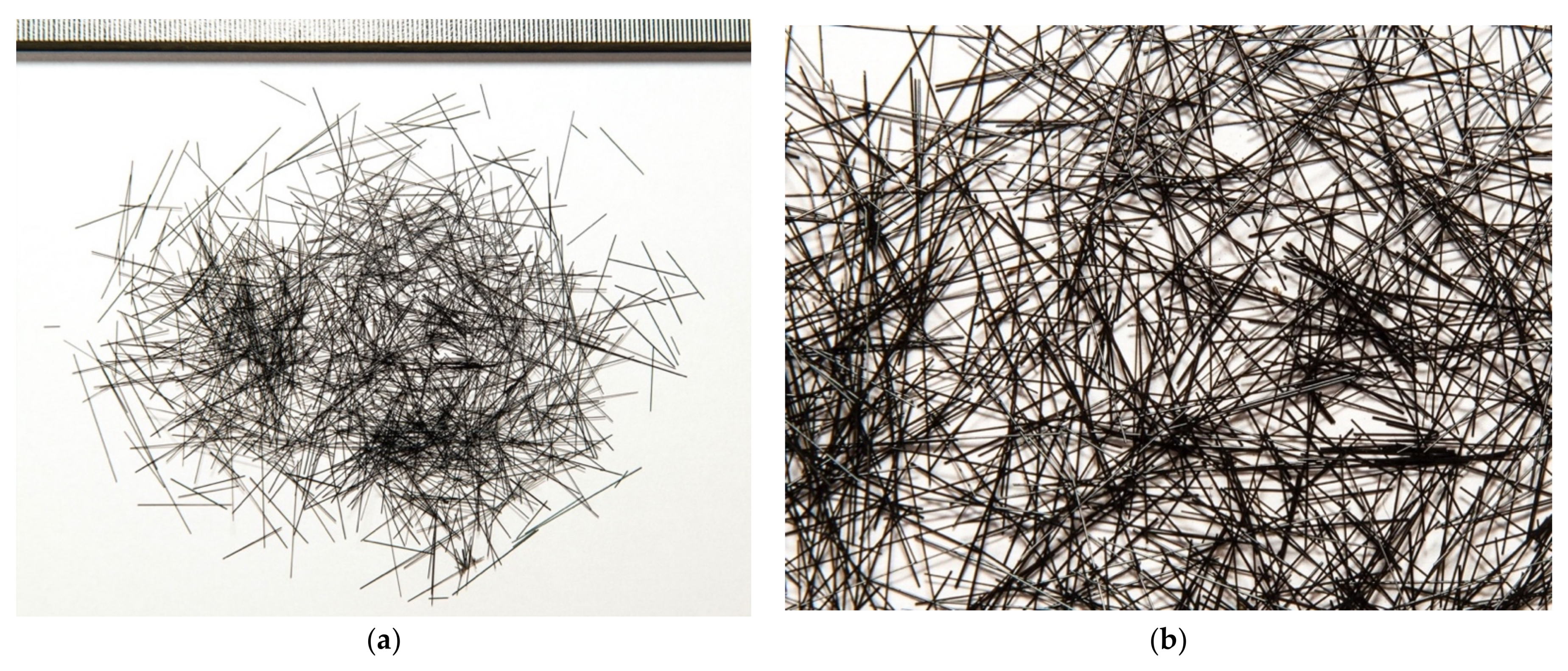
Coarse basalt fiber was used to manufacture dispersed-reinforced FRC, the properties of which are shown in
Table 4.
The photo of coarse basalt fiber is shown in
Figure 1.
In the technology of FRC preparation, the most important moment is the addition of fiber into the concrete mixture, ensuring its uniform distribution throughout the entire volume. First, the dry mortar part with fiber was prepared. Second, mixing of the incoming mixer for water and coarse aggregate, simultaneously, was conducted.
Cement and sand were first poured into an operating mixer with a capacity of 0.085 m3 and a rotor speed of 500 rpm, which were mixed for 1.5 min with the simultaneous supply of fiber. Only then was the water and coarse aggregate fed. Uniform supply of fiber was provided by a special vibrating chute, through which pre-dosed coarse basalt fiber was fed into the concrete mixer.
The total mixing time of the FC mixture with heavy crushed stone did not exceed 3.5 min, and with expanded clay gravel, 4 min. Compaction of the concrete mixture was carried out on a laboratory-vibrating platform, providing vertical-directional vibrations (up to 300 vibrations/min) with an amplitude of 0.5 mm. The vibration time for a mixture of conventional samples and FRC did not exceed 10 s.
Before the manufacturing of experimental BFRC columns, trial mixes were performed, providing the strength of heavy and structural expanded clay concrete equal to 25 MPa on the 28th day of hardening. Consumption of materials by weight for the preparation of 1 m
3 of a concrete mixture is shown in
Table 5.
The experiments were carried out on cubes 150 mm × 150 mm × 150 mm and prisms with sections of 150 mm × 150 mm and a length of 600 mm. For each type of concrete, 10 cubes and 5 prisms were made and tested for compression. A total of 40 sample cubes and 20 prisms were made. Tests were carried out on hydraulic presses, P-50 and P-125, following GOST 10180-2012. The sample stresses increased at a constant rate of 0.05–0.06 MPa per second until the moment of crushing. Longitudinal and transverse strains in the prisms were measured using an automatic strain gauge AID-4M, using strain gauges with a base of 50 mm, glued to all four lateral surfaces of the sample.
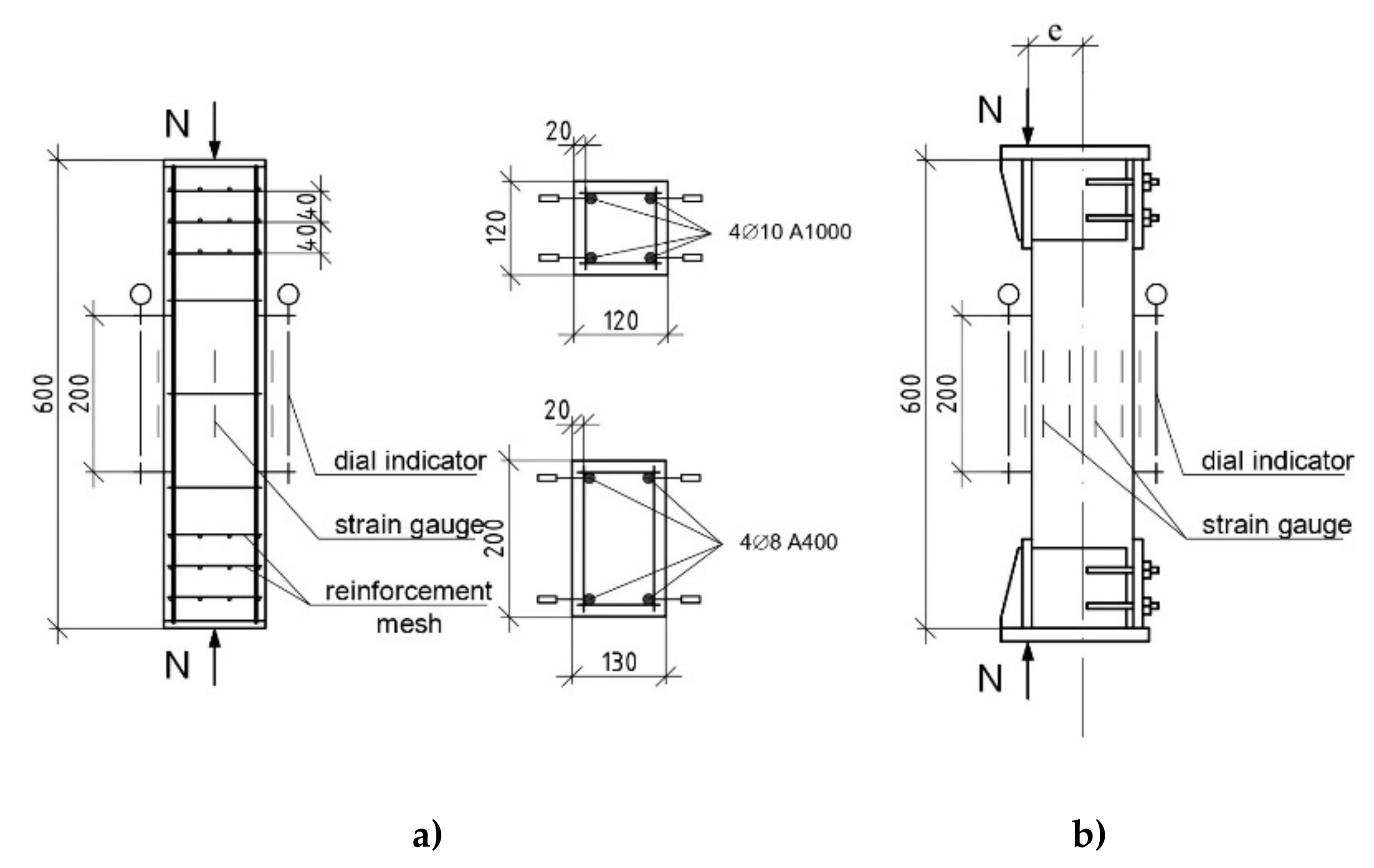
Experimental studies of ultimate compressive strains in reinforcement and concrete under central and eccentric compression were carried out on short reinforced concrete racks of two standard sizes 120 mm × 120 mm × 600 mm and 130 mm × 200 mm × 600 mm.
The first group of specimens, which was tested for axial compression, was reinforced symmetrically by four rods with a diameter of 10 mm with high-strength bar steel of class A1000 (reinforcement percentage 1.3%), and in the transverse direction with stirrups made of A240 steel, with a diameter of 6 mm, with a pitch of 150 mm (code racks T-1, TF-2, K-3, Kf-4). The second group was loaded with a relative eccentricity of the longitudinal force = 0; 0.15 and 0.6, and was reinforced symmetrically with four rods, with a diameter of 8 mm with rod steel of class A400 (percentage of reinforcement 1.4%), and in the transverse direction with stirrups made of steel A240, with a diameter of 6 mm, with a spacing of 150 mm (code racks KK-0, KK-0.15, KK-0.6, KKF-0, KKF-0.15, KKF-0.6).
The design and test scheme for samples of the second series is shown in
Figure 2.
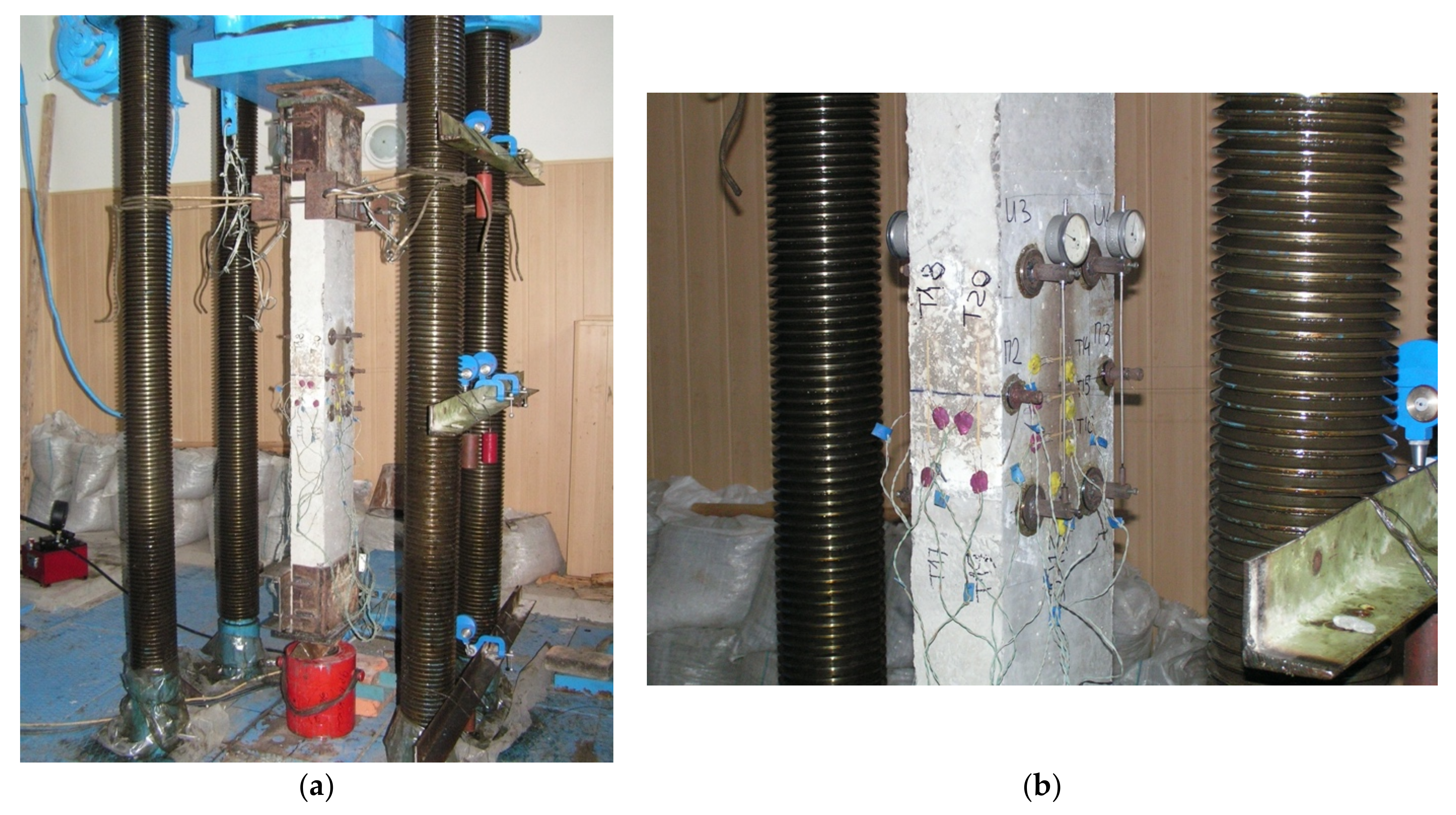
Testing of short reinforced concrete columns was carried out on a P-125 hydraulic press. To prevent the fall of the samples after crushing, the struts were attached in the upper part with flexible ties to the guides of the traverse of the hydraulic press (
Figure 3).
During the test, the loading of the samples was carried out in steps of 0.1 of the breaking loads. At each loading stage, the column’s deflections in the middle and in the support sections were measured. Longitudinal deformations in the middle section of the column were estimated using chains of strain gauges with a base of 50 mm, glued to the compressed and tensile (less compressed) faces, as well as lateral surfaces. On the edges of the column, the chains of strain gauges were glued in one row, and on the side surfaces—3 rows each with a distance between rows of 4 cm. In the middle section, indicator strain gauges with a measurement base of 20 cm were additionally installed on the reinforcement (on external benchmarks), as well as on the side surface columns as indicated (
Figure 3).
When testing columns with an eccentricity (= 0.15; 0.6), steel inventory heads were put on the end sections of the columns, on the endplates of which there were slots for hinged knife supports.
For each stage of loading, the formation of cracks, the width, and height of their opening were recorded.
According to the test results, graphs of dependence were built and where is compressive strength of the concrete, is stress in reinforcement, is compressive strain in the concrete, and strain in reinforcement.
The peak values fc (with the crushing of the columns) and the peak value according to the graph were also determined.
Additional control of strain was recorded by dial indicators with scale divisions of 0.01 and 0.001 mm. The experimental results were processed using mathematical statistics methods.
3. Results of Testing Cubes and Prisms from Heavy and Light Expanded Clay BFC
The change in the strength of the concrete, of experimental compositions on light and heavy aggregates, with and without fiber, was determined by the results of the testing cubes at 28 days of age (
Table 6).
The test results for cubes shown in
Table 6 show that fiber reinforcement has a positive effect on increasing the strength of concrete on heavy- and lightweight aggregates. All else being equal, on the 28th day of hardening, the average strength indicators of heavy concrete was
R = 24.1 MPa, and for fiber-reinforced concrete was
Rf = 25.6 MPa. Thus, the actual increase in strength was 1.5 MPa or 6%.
The effect of fiber on increasing the strength of concrete on a lightweight aggregate was more noticeable. The average strength of concrete without fiber was 21.3 MPa, and fiber-reinforced concrete cubes showed strength of 23.4 MPa. The actual increase in strength was 2.1 MPa or 10%. This effect is due to the fact that, when mixing the concrete mixture, rounded expanded clay grains damage fibers to a lesser extent than gravel grains.
The measurement of the deformability of concrete on light and heavy aggregates under compression was determined by the results of testing prisms at 28 days of age (
Table 7).
The test results of the prisms (
Table 7) show that fiber reinforcement has a positive effect on increasing the strength and deformability of concrete on heavy and light aggregates. On the 28th day of hardening, the average values of the prismatic strength of heavy concrete were 18.3 MPa, and for fiber-reinforced concrete, 21.3 MPa. Thus, the actual increase in prismatic strength was 3.0 MPa, or 16%. Ultimate strains corresponding to the ultimate compressive strength of concrete were 1.87 × 10
−3 and 2.24 × 10
−3 in FRC (the increase in ultimate deformability was 19.8%).
In concrete on lightweight aggregate, the average value of the prismatic strength of heavy concrete was 18.5 MPa, and in fiber-reinforced concrete 21.8 MPa (an increase in prismatic strength by 3.3 MPa or 18%). Ultimate strains corresponding to the ultimate compressive strength of concrete were 2.26 × 10⁻³ and 2.85 × 10⁻³ in FRC (the increase in ultimate deformability was 26.1%).
The coefficient of transition from cubic strength to prismatic
(
Table 7) for expanded clay FRC was higher than that of specimens not reinforced with fiber. The actual values of Poisson’s ratio in the lightweight FRC ranged from 0.22 to 0.27, exceeding the normalized value.
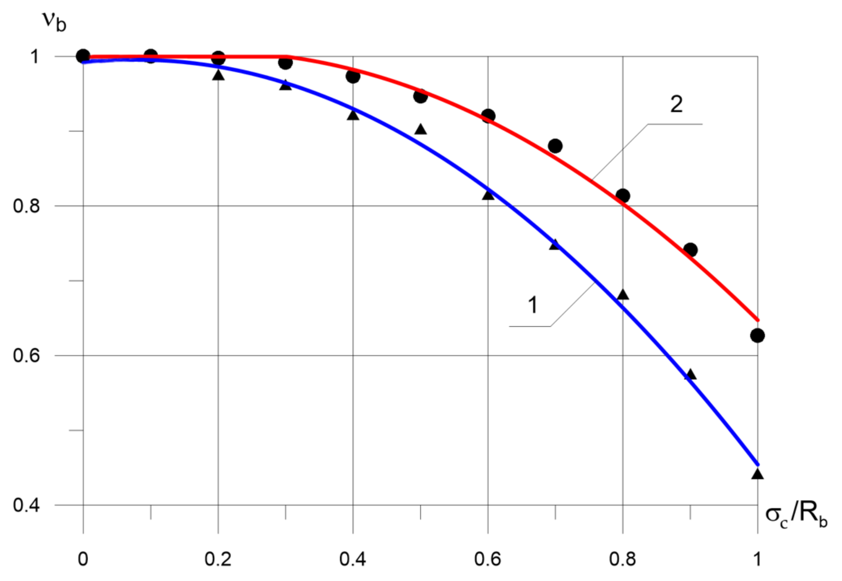
The change in the ratio between an elastic and total strain with increasing stresses is presented in
Figure 4, which shows the dependence coefficient of elastic–plastic on the stress–strain level
. The coefficient of elastic–plastic strain is the ratio of the elastic strain of concrete to the total strain, measured at different loading levels.
In contrast to heavy concrete, the non-linear nature of strain in lightweight concrete appears earlier. Thus, the coefficient of elastic–plastic strain becomes less than one at a ratio in the range of 0.26–0.35, and upon further strain, it decreases relatively uniformly with an increase in stresses, i.e., almost linearly until crushing. In heavy concrete, with an increase in stresses and the development of microcracks, the rate of growth of plastic strains increases sharply, the proportion of elastic strains decreases, while in lightweight concrete, this process is less intense. The coefficient of elastic–plastic strains at a load level of 0.8–0.9 changed for expanded clay FRC within 0.88–0.79, significantly exceeding the value adopted in SNiP 2.03.01.84. To the greatest extent, the features of the elastoplastic properties of FRC manifested during crushing at . The ultimate coefficient of elastic–plastic strains, values increased in heavy FRC by 6–8%, and in expanded clay FRC, ranged from 11 to 27%.
Fiber reinforcement significantly affected the value
. Thus, the coefficient of elasticity at a load level from 0.75
to 0.8
varied in elements made of structural expanded clay concrete within 0.83–0.7. To the greatest extent, the features of the elastoplastic properties of FRC were manifested during crushing; that is, at
= 1. Therefore, the coefficient of elastic–plastic strains of samples with fiber was of greater importance than unreinforced (
Table 7). In general, for FRC with a strength of 20–25 MPa, both on a conventional aggregate and on a lightweight expanded clay aggregate, higher values of the coefficient of elastic–plastic strains
are characteristic than for concrete without fiber.
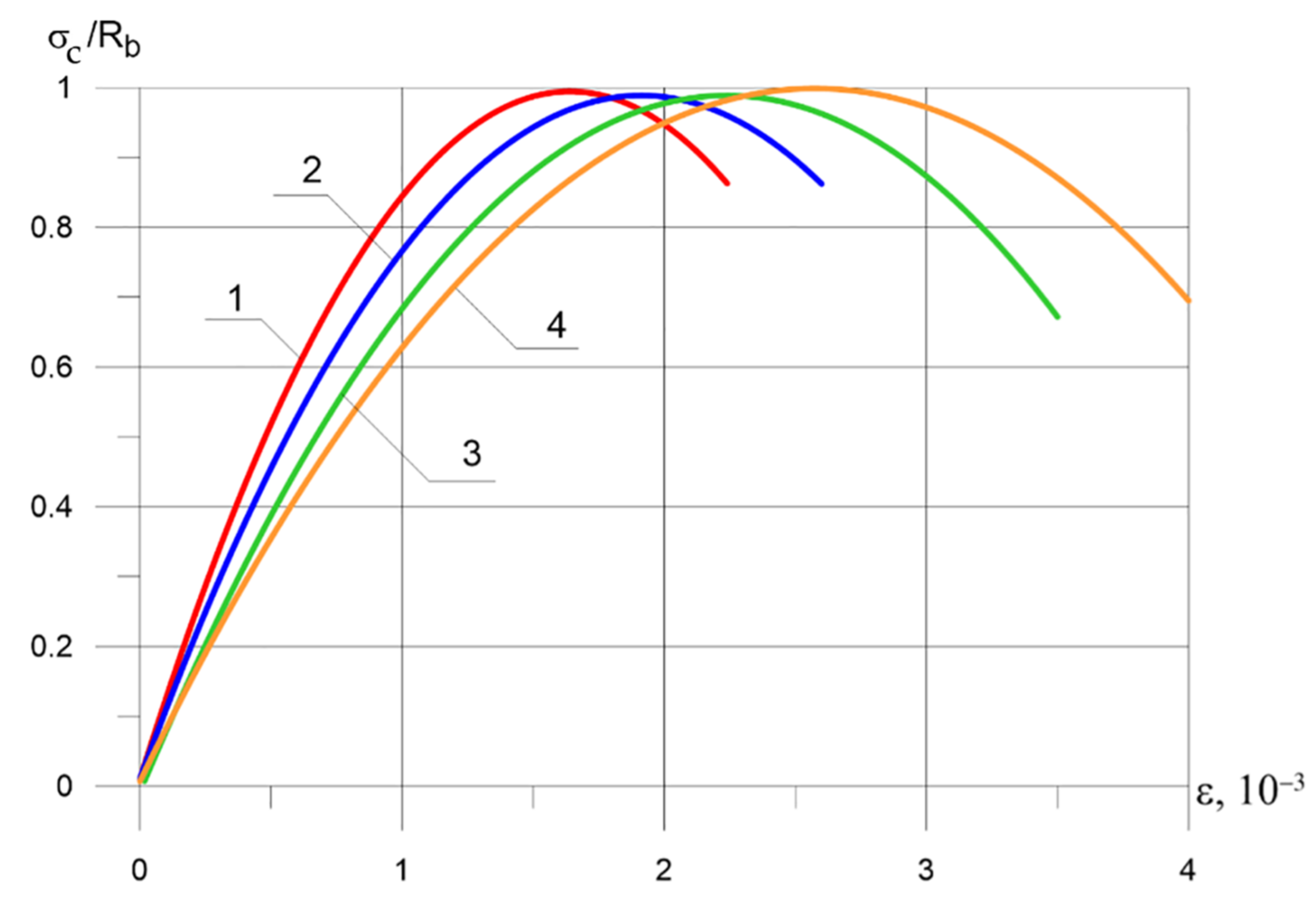
Figure 5 shows that the strain diagrams of heavy concrete and expanded clay concrete were different, although they had approximately the same strength. The curves are plotted in relative values for easy comparison of the deformability of the samples.
Thus, in the calculation and design of expanded clay concrete elements, the increased deformability of the FRC should be taken into account. In particular, the ultimate compressibility of expanded clay FRC at = 10% can be increased by 1.3 times; that is, it can be taken at short-term loading equal to 2.6 × 10⁻³, and the limiting elongation can be taken equal to 0.5 × 10⁻³; that is, 2 times more than for concrete without fibers.
4. Results of Testing Short Columns
4.1. Load Bearing Capacity
All 10 samples of short columns, following the experimental studies program (series of tests no. 2), were tested by short-term loading until fracture. Six columns were tested for axial compression, two with relative eccentricity = 0.15, and two with eccentricity = 0.6.
The failure of specimens without fiber reinforcement under axial application of an acting force was caused by the concrete crushing in compression in the middle of the columns. Immediately before the destruction of the concrete in the compressed zone, the formation of cracks was observed. Longitudinal cracks appeared, and the concrete cover was punctured in the middle part of the sample. In specimens reinforced with fiber with a centrally applied force, the nature of the destruction was identical. However, the moment of appearance of cracks in concrete along the longitudinal reinforcement corresponded to higher compressive stresses = 0.88–0.92, and the width of their opening was significantly smaller.
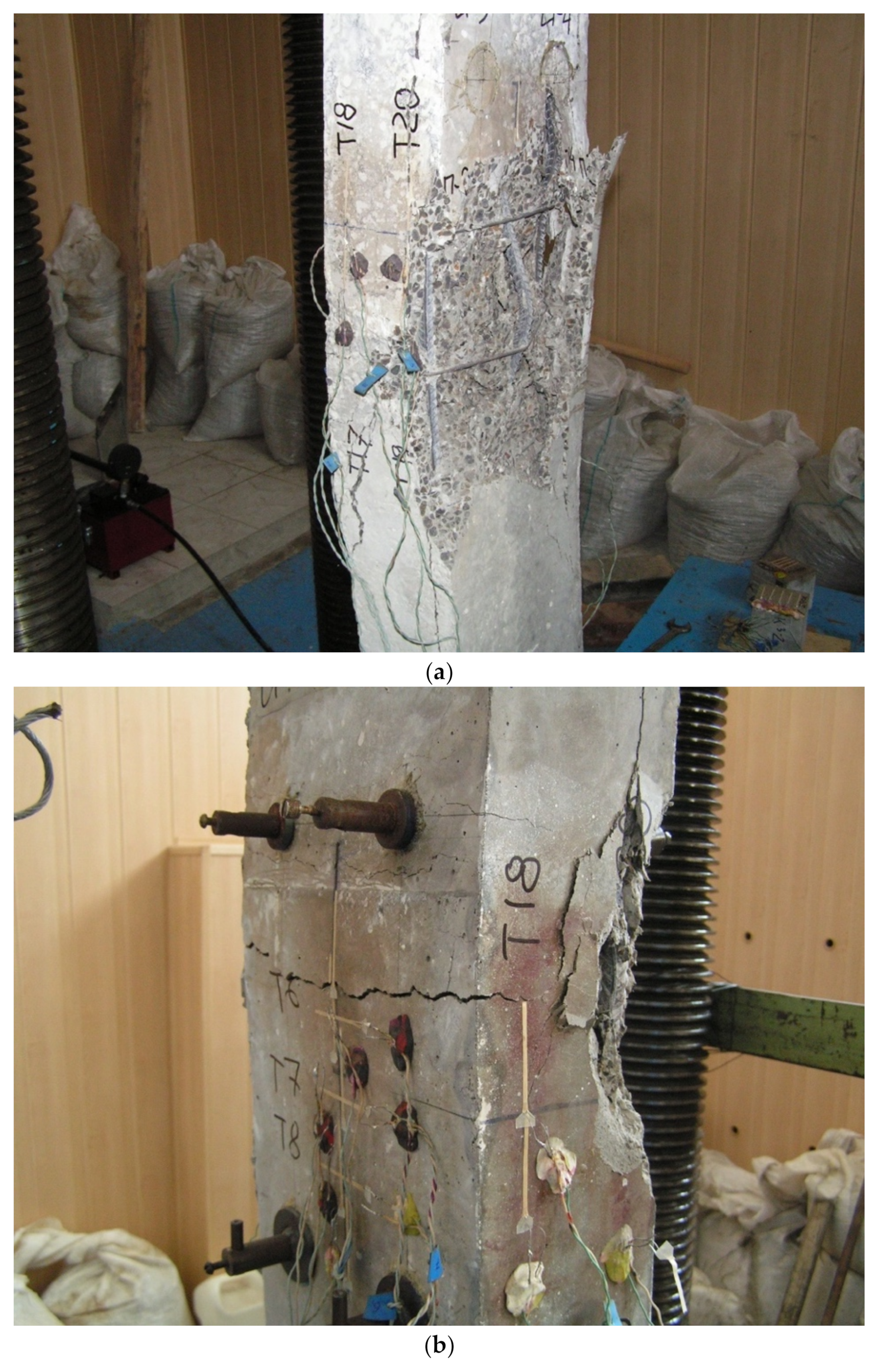
Figure 6 shows the fracture of two samples tested for the action of a compressive force with eccentricities
= 0.15 and
= 0.6 (codes KKF-0.15 and KKF-0.6)
Under the action of a longitudinal force with a small relative eccentricity = 0.15, the section of the element had an insignificant tensile zone. Accordingly, the reinforcement was subjected to compression, and the reinforcement , located at the face further from the longitudinal force, was subjected to tension. The element crushing, in this case, began from the side of the compressed zone, while the second case was observed when the condition was met (where is the relative height of the concrete compression zone, x is a coordinate and is the cross-sectional height, and is the boundary value of the relative height of the concrete compression zone, is a coordinate in tensile zone).
With an eccentric application of a force with small eccentricities, the crushing of expanded clay basalt fiber reinforced concrete (BFRC) of short columns, as well as in the samples described above, occurred from the concrete crushing in compression zone, while the stress in the reinforcement further from the line of action of the external force did not reach the yield point. A general view of the prototype during testing is shown in
Figure 1. Actual strains (both compression and tension) in specimens with conventional reinforcement varied from 7.0 to 13%, and in models with combined reinforcement, from 11.7 to 28%.
The columns tested with a relative eccentricity = 0.6 failed due to reaching the ultimate stresses in the tensile reinforcement. The achievement of ultimate stresses in the compressed zone of concrete was observed almost simultaneously.
The theoretical bearing capacity of the columns under axial compression was determined by the formula:
where
and
are the calculated resistance of concrete and reinforcement;
and
are the cross-sectional area of the sample and the total area of the longitudinal reinforcement.
The theoretical bearing capacity of the racks tested with the applied force eccentricity was determined by solving the system of equations:
where
e is eccentricity of the external force application relative to the center of gravity of the stretched or least compressed reinforcement;
x is the height of the compressed zone of concrete;
h0 is working height of the section (distance from the extreme compressed concrete fiber to the center of gravity of the stretched or least compressed reinforcement);
—stresses in compressed reinforcement;
—cross-sectional area of compressed reinforcement;
a—distance from the center of gravity of the tensioned or least reinforcement to the extreme tensioned concrete fiber;
—stresses in tensile or least compressed reinforcement;
—sectional area of tensile or least compressed reinforcement.
The tests results showed that the bearing capacity of short reinforced concrete racks is influenced by both factors varied in the experiment; the relative eccentricity of the external force and the version of the reinforcement of the samples (conventional or combined).
Columns made of expanded clay BFRC showed a higher bearing capacity than columns made of expanded clay concrete at all external force application eccentricities (
Table 8). With a relative eccentricity of
= 0.15, the actual breaking load for the expanded clay FRC rack with the KKF-0.15 code was 7.6% higher than for the similar one made of expanded clay concrete, and at
the noted excess it was 13.5%.
In
Table 8, the codes of the experimental specimens are as follows. T-1 is a column made of heavy concrete, tested for axial compression
= 0 (steel reinforcement 4Ø10 A1000); TF-2 is a column made of heavy fiber-reinforced concrete, tested for axial compression
= 0 (steel reinforcement 4Ø10 A1000); K-3 is column made of expanded clay concrete, tested for axial compression
= 0 (steel reinforcement 4Ø10 A1000); KF-4 is a column made of expanded clay-fiber-reinforced concrete, tested for axial compression
= 0 (steel reinforcement 4Ø10 A1000); KK-0 is a column made of expanded clay concrete, tested for axial compression
= 0 (steel reinforcement 4Ø8 A400); KK-0.15 is a column made of expanded clay concrete, tested for eccentric compression
= 0.15 (steel reinforcement 4Ø8 A400); KK-0.6 is a column made of expanded clay concrete, tested for eccentric compression
= 0.6 (steel reinforcement 4Ø8 A400); KKF-0 is a column made of expanded clay-fiber-reinforced concrete, tested for axial compression
= 0 (steel reinforcement 4Ø8 A400); KKF-0.15 is a column made of expanded clay-fiber-reinforced concrete, tested for eccentric compression
= 0.15 (steel reinforcement 4Ø8 A400); KKF-0.6 is a column made of expanded clay-fiber-reinforced concrete, tested for eccentric compression
= 0.6 (steel reinforcement 4Ø8 A400).
An increase in the relative eccentricity of the external force in all cases led to a decrease in the columns’ bearing capacity. At the same time, the degree of reduction in the bearing capacity slightly depended on the type of concrete, and was 79%.
Analysis of the results of testing short column-pillars for axial compression (T-1 and TF-2, K-3 and KF-4, KK-0 and KKF-0) oбpaзцы showed (
Table 8) that, other things being equal, specimens with combined reinforcement had peak load values on average 11–12% higher than pillars with conventional, traditional reinforcement. Simultaneously, the degree of increase in the bearing capacity of the test racks did not significantly depend on the type of concrete.
To compare the experimental and theoretical values of the bearing capacity of short columns, the latter were calculated according to the norms’ methodology, taking into account the actual strength of concrete and reinforcement, determined empirically. To determine the theoretical bearing capacity, the actual stress–strain diagrams for compressed concrete were used, shown in
Figure 5. The calculation results showed that the discrepancy between the experimental and theoretical values of the peak load is quite large, and the maximum ratio reaches 23.0% for all tested elements. Thus, the experimental peak load in expanded clay-reinforced concrete specimens with the KKF-0 code exceeded the theoretical one, calculated according to the current standards, considering the actual characteristics of materials by 17%.
In heavy concrete (samples T-1 and TF-2), the indicated difference between the peak load’s experimental and theoretical values was 20 and 18%, respectively. In our opinion, the main reason for this is because the norms of the limiting compressive stresses in the reinforcement of the compressed zone are not considered, which increase as a result of the fiber reinforcement of the samples.
The specimens crushing without fiber was transient: when the peak value was reached on the force meter, a rapid decrease in the bearing capacity in the specimens was observed without a significant increase in the ultimate longitudinal strains. In specimens with fiber, especially from constructive expanded clay BFRC, the picture of crushing has changed dramatically. In particular, when the peak load in expanded clay BFRC samples with the code KF-4, KKF-0, KKF-0.15 was reached, the process of destruction seemed to stretch over time: the load on the force meter remained practically unchanged (decreasing or increasing within 1.5–2%), while reinforcement strains increased at a tremendous rate. The absolute values of strains in such a prolonged stage of fracture were approximately 2–2.5 times greater than the strains recorded at the moment of reaching the peak load.
4.2. Ultimate Strain of Concrete and Reinforcement in Test Columns
When assigning the design resistances of reinforcement
RSC, the current standards take into account not only the properties of steel, but also the possible ultimate compressibility of concrete. When testing short columns with high-strength reinforcement class A1000 for axial compression, the strains of concrete in specimens reinforced with fiber exceeded similar strains of specimens without fiber, not only in the ultimate supercritical stage of operation, but also over the entire range of increasing load (
Table 9).
An increase in the value of the peak load during testing led to an increase in the ultimate compressibility of concrete, which in turn led to an increase in the actual values of the ultimate compressive stresses in the reinforcement. It was experimentally established that the ultimate compressive stresses in the reinforcement of reinforced concrete elements with fiber reinforcement are higher than in similar ones without fiber. In particular, under axial compression, the discrepancy
in the samples of expanded clay concrete with fiber was 18.1% and 12.3%, respectively. The given curves’ analysis shows that in the specimens-racks with combined reinforcement, the ultimate compressive strains in reinforcement and concrete were higher than in the same specimens but without fiber. Thus, the actual limiting values of strains in samples of heavy concrete with
= 0 (code T-1) were
, and with fiber
(
Table 9). Even higher values of ultimate compressive strains were obtained in expanded clay concrete specimens. In particular, in racks made of lightweight concrete with the code K-3 (without fiber), the ultimate values were
= 2.65
and expanded clay BFRC
= 3.05
.
In expanded clay BFRC specimens reinforced with standard hot-rolled steel grade A400, the actual ultimate compressive strains in the reinforcement were significantly higher than the ultimate compressive strains recorded in the columns without fibers. With an eccentric load application, the limiting compressive stresses in the reinforcement of the compressed zone increased even more (samples with the codes KK-1 and KKF-1). The absolute values
in the reinforcement class A1000 with forces of 0.98
reached 520 MPa, exceeding the standardized SP 63.13330.2018 [
30], up to 30%. At the same time, at the same load level (the forces perceived by the structures during their operation were taken
as the baseline), the actual stresses in the reinforcement of the FRC of the samples were lower than in the racks without fibers.
It should be noted that, in quantitative terms, the ultimate compressive strains of concrete in short columns with combined reinforcement with steel of the A400 class and fiber were lower than those of similar FRC specimens reinforced with high-strength steel of the A1000 class. Nevertheless, the general tendency to increase the ultimate compressive strains in samples with fiber is traced during data processing in all tested racks.
Ultimate compressive strain of concrete in specimens with combined reinforcement exceeded similar strains in specimens without fiber. In the case of axial compression, the absolute values in the racks made of expanded clay BFRC with a section of 120 mm × 200 mm were from 2.41 to 2.75 , and in the samples without fibers, respectively, from 1.94 to 2.21 . With an increase in the longitudinal force’s relative eccentricity, fiber reinforcement efficiency in this group of samples also increased. Therefore, the ultimate values and in the samples with the code KKF-0.15 and KKF-1 exceeded the normalized ones by 12–18 and 33–46%, respectively.
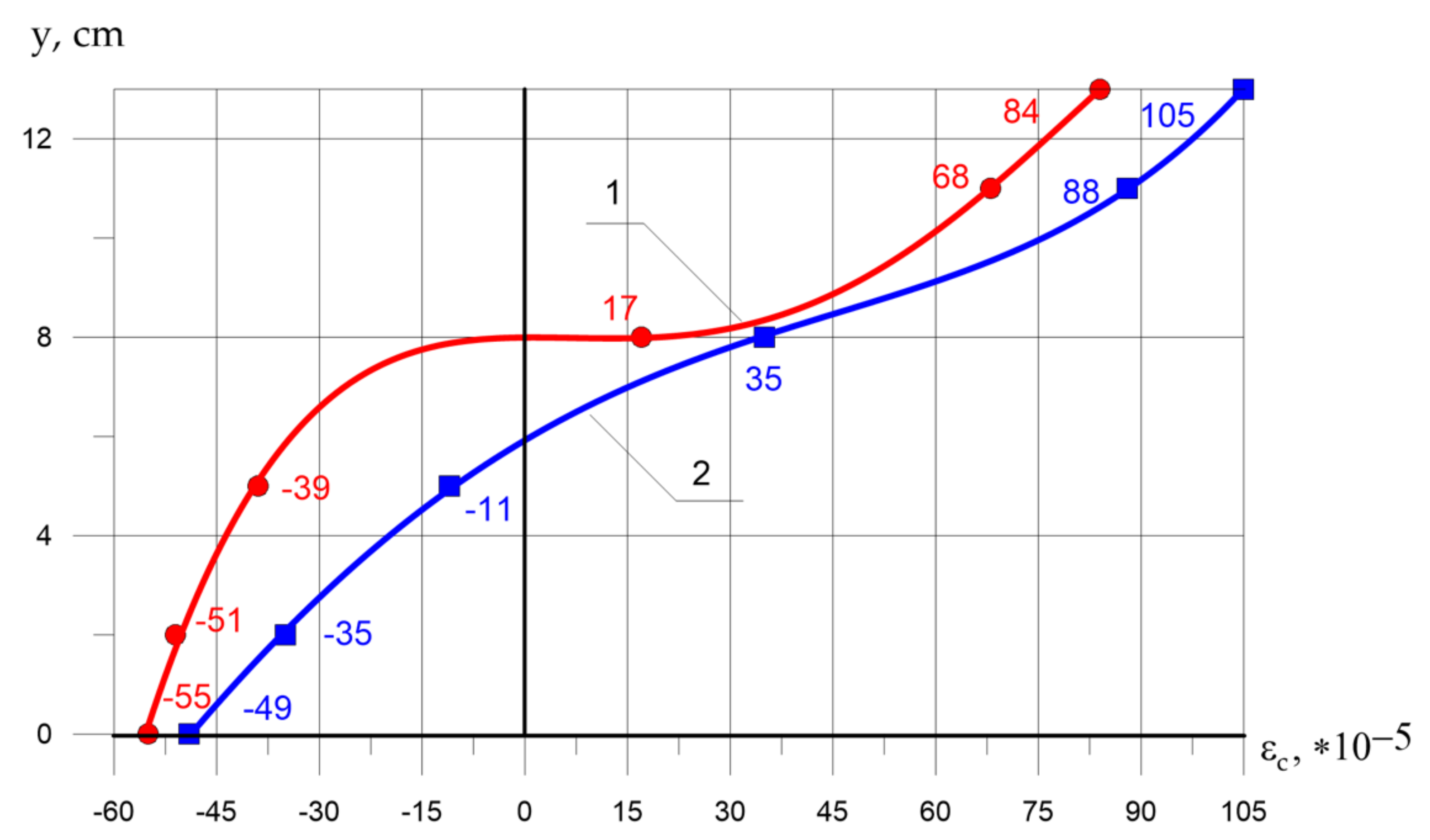
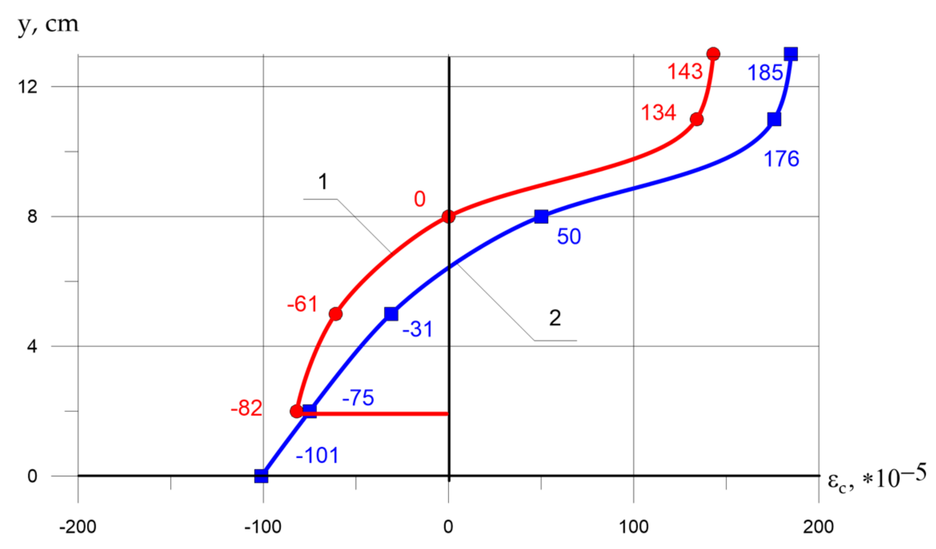
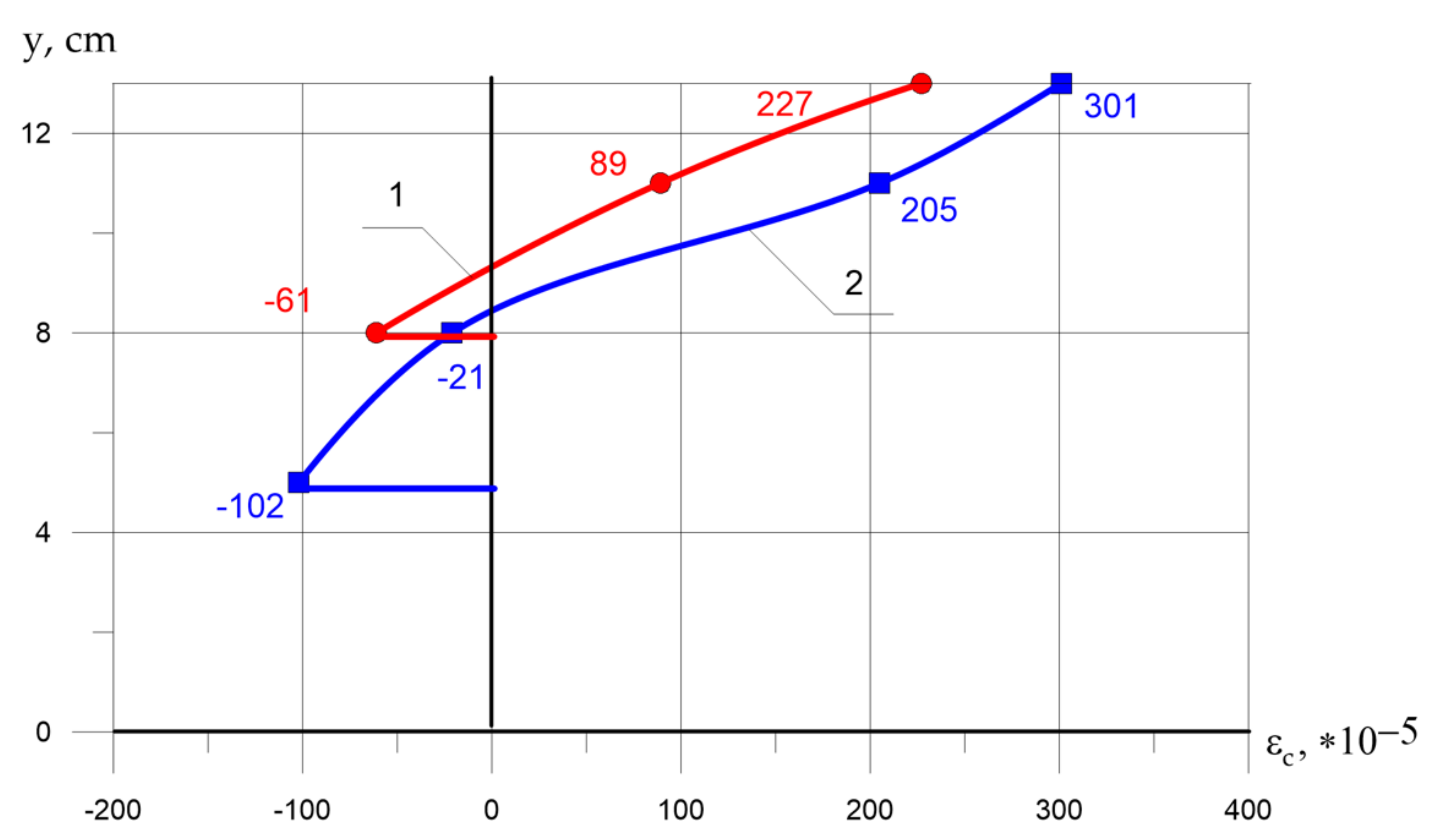
Figure 7,
Figure 8 and
Figure 9 show strains in concrete of prototypes tested with relative eccentricity
= 0.6 at load values of 60, 90, and 120 kN, respectively. The
y-axis represents the coordinate of the section height from one tensile edge
y = 0 to another compressed
y = 13 cm. The abscissa represents the longitudinal strains of concrete
in the cross-section y from 0 to 13 cm. The positive area of the diagram refers to the compression zone, negative to the zone of tension.
As can be seen in
Figure 7, the longitudinal strains of concrete in the cross-section in the compressed zone of expanded clay of fiber-reinforced concrete elements (blue graph in the positive area of the diagram) are greater than similar values for specimens without fiber (red graph in the positive area of the diagram) at the same external load values. In the tensile zone, the opposite trend is observed: tensile strains are restrained by the fibers and are noticeably less than the values in expanded clay concrete without fiber.
Figure 8 shows that the tendency of strain in the compressed zone is the same and the strain of the fiber-reinforced concrete elements is greater than without fiber. In the tensile zone, it can be seen that, at a given load level, the concrete without fiber has a crack (solid horizontal red line), while the sample with fiber works without cracks.
Figure 9 shows that at a load of 120 kN, both samples work with a crack in the tension zone (there are no data on strains in the tensile zone on the graphs), but the sample with fiber has a crack to a height of 5 cm, and without fiber to 8 cm.
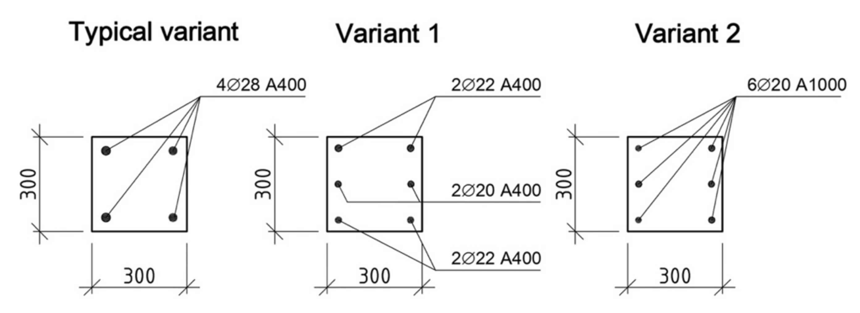
4.3. Redesign of Typical Columns Taking into Account the Increase in Bearing Capacity
To determine the effectiveness of the considering the actual stresses in reinforcement bars and fiber-reinforced concrete, the standard prefabricated RC column was recalculated. In the calculation, heavy concrete was replaced by expanded clay concrete of equal strength (variant 1) and using reinforcement with a resistance of 1000 MPa (variant 2). The design of standard precast concrete columns is shown in
Figure 10.
A typical precast reinforced concrete column has a cross-sectional area of 300 × 300 mm, length L0 = 4500 mm. Longitudinal reinforcement consists of four rods with a diameter of 28 mm, class A400 (4Ø28 A400).
The calculation of the columns (
Table 10), carried out considering the proposals, showed that the addition of fiber from coarse basalt fiber makes it possible to reduce the consumption of reinforcement compared to a typical column.
Considering the replacement of heavy concrete with expanded clay concrete with fiber (option 1), and strain hardening, the consumption of working reinforcement can be reduced by 12.8% (4Ø22 + 2Ø20 A400). When using reinforcement with a resistance of 1000 MPa in a column, its consumption can be reduced by 23.4% (6Ø20 A1000).
Thus, the correct consideration of the compressive stresses in the reinforcement and concrete of compressed columns made using fiber from coarse basalt fiber gives a significant effect, expressed in a significant reduction in steel consumption and a decrease in the mass of the structure, which in turn reduces transport and installation costs.
5. Discussion
It should be noted that an increase in the actual value of the ultimate compressibility of concrete in specimens with dispersed reinforcement influenced the change in the complete strain diagram, with a record of the descending branch.
The strain diagrams of concrete prisms made of heavy concrete on the ascending branch had a sufficiently steep rise in both conventional and FRC specimens. The actual ultimate strains for this group of samples turned out to be slightly higher than the standardized ones. Therefore, at the ultimate stage, they were within 2.70·10−3–3.60·10−3. However, in strain at the stage of fracture in the descending section, the curves differed quite significantly.
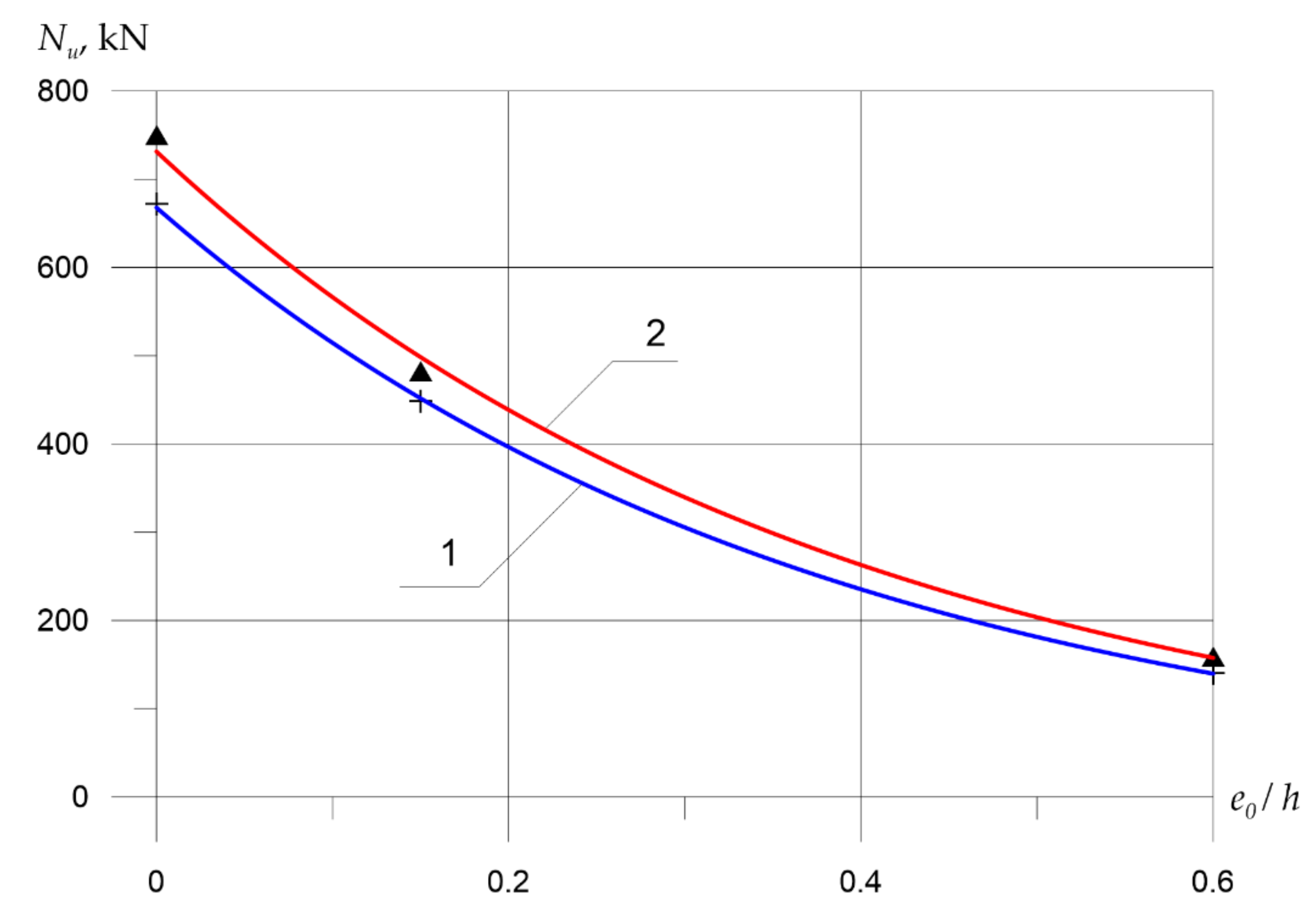
Figure 11 shows the dependence of the racks’ bearing capacity on the amount of eccentricity for columns without fiber and with 10% basalt fiber. It can be seen that in the considered range of relative eccentricity, structures with basalt fibers have a higher bearing capacity. Similar results were obtained by Wang et al. [
31], in which the properties of the geopolymer concrete crushing reinforced with basalt fiber are investigated. Tests [
30] were carried out for compression, splitting, and three-point bending. The results show that the addition of 6 to 12% basalt fiber improves compressive strength, tensile strength, and fracture toughness. Comparison of our results with studies [
31] shows that the combination of FRC with the effective use of high-strength steel reinforcement will increase the columns’ bearing capacity and reduce material consumption.
Ramesh et al. studied the use of concrete reinforced with basalt fiber with a volume fraction of 0–2% without steel reinforcement [
32]. The authors showed that the inclusion of basalt fibers in 1.5% increases the modulus of rupture while not significantly affecting the compressive strength. Compared to the control concrete sample, the mechanical characteristics of concrete reinforced with basalt fiber by 1.5% increase from 9% to 22%.
Comparison with the results obtained by Polskoy (in [
33]) shows that reinforcement with composite materials in the transverse (at
= 0) and longitudinal (at
= 0.32
h) directions demonstrated sufficiently high strength. This made it possible to use external reinforcement to increase the bearing capacity of compressed elements, despite exceeding the standard values of the section dimensions
b/h = 0.2, which is more than 1.5, and the flexibility of the elements strengthened
λh = 20 >
λh = 14.
If, for ordinary samples-prisms, the process of destruction proceeded very quickly, in particular, in the range of load drop up to 0.8, for samples without fibers it sharply decreased, after which complete crushing occurred, then for FRC, this section had a smoother fall, while the strains increased by 1.87 times. The effect of fiber is even more noticeable on the total strain diagrams for lightweight concrete specimens. If in ordinary expanded clay concrete samples, the process of destruction occurred, as in heavy concrete, very intensively (peak longitudinal strain were within –), then for dispersed reinforced samples, a much more plastic nature of strain is characteristic. A distinctive feature of the obtained diagrams is the presence of a plastic strain stage, which is expressed by rather flat horizontal descending sections in the diagram . In this case, the descending section’s slope is primarily determined by the nature of the destruction.
Xu et al. [
13] showed the possibility of using basalt fiber to develop cement composites, similar to our results. The authors show that basalt fiber-reinforced concrete exhibits unique strain hardening and multiple cracking characteristics. The BFC tensile curve is relatively smooth, which corresponds to the curves obtained in this work in
Figure 3. The average crack width is less than 10 microns and the distance between the cracks is less than 3 mm. The unique features of the BFRC are interpreted [
13] based on the behavior of basalt fibers as bridges.
6. Conclusions
This experimental study was aimed at studying the effect of a particular type of fiber on the strength and strain properties of concrete. The use of high-strength reinforcement in ordinary concrete is useless due to the limitations of the deformability of the compressed zone of concrete. The introduction of coarse basalt fiber into the concrete composition increases the ultimate tensile strength of the concrete. The condition for the compatibility of work of concrete and reinforcement bars makes it possible to use reinforcement of a higher strength class, capable of increasing the bearing capacity of the column with increased deformability. Simultaneously, for calculating the bearing capacity, it is possible to use the value of the ultimate stresses in the reinforcement 520 MPa, which is 30% higher than the standard value in SP 63.13330.2018 [
30]. Considering this factor in the calculation and design will make it possible to achieve greater bearing capacity and efficiency of structures due to the possibility of using reinforcing steel bars with higher resistance.
The addition of 10% fiber from coarse basalt fiber increased fine-grained concrete’s actual strength with a design strength of 25.0 MPa on ordinary crushed stone by 9.0%, and structural expanded clay concrete of the same design strength up to 12%. Dispersed fiber reinforcement had a positive effect on the scale factor. Thus, the difference in cube strength parameters made of expanded clay concrete with an edge from 7.07 to 15.0 cm reached 7.2%, and in similar ones with fiber from 1.9 to 3.6. The “narrowing” of the specified parameter is explained by the introduction of fiber, which creates a “reinforced” cage around the expanded clay grains, preventing its premature crushing.
It was found that the load level corresponding to the formation of microcracks when testing prisms made of structural expanded clay FRC was from 29 to 42% higher than that of ordinary expanded clay concrete. The increase in prism samples with fiber on a conventional aggregate was 12%, and on expanded clay, 26%.
Ultimate compressive strains in BFRC concrete of columns with combined reinforcement were higher than in similar specimens without fibers. Under axial compression, the absolute values in the uprights on a light aggregate increased by 1.42 times, and on a heavy one by 1.19 times. In the case of eccentric compression with a relative eccentricity of 0.6, the values increased even more, while their absolute values in the expanded clay FRC samples reached, and in similar ones without fibers 2.4 .
Under axial compression, the addition of 10% fiber in the samples of expanded clay concrete and heavy concrete increases the ultimate stresses in the reinforcement in compression by 18.1 and 12.3%, respectively. With an eccentric load application, the ultimate compressive stresses in the reinforcement of the compressed zone increased even more (samples with the codes KK-1 and KKF-1). The absolute values in high-strength reinforcement class A1000 at forces of 0.98 reached 520 MPa, exceeding the standardized SP 63.13330.2018 by up to 30%, and in column specimens reinforced with hot-rolled steel of class A400 increased to 19%. At the same time, at the same load level (the forces perceived by the structures during their operation were taken as the baseline), the actual compressive stresses in reinforcement and concrete in FRC samples were lower than in similar resistant ones without fibers.
Analysis of the results of testing short columns for axial compression showed that prototypes with fiber reinforcement, all other things being equal, had peak load values that were 11–12% higher than those with conventional reinforcement. At the same time, the degree of increase in the bearing capacity of the test racks did not significantly depend on the type of concrete. With an eccentric load application, the actual bearing capacity, in short, expanded clay BFRC columns exceeding the calculated one by up to 23%.


 ,
, 


