1. Introduction
Thermoelectric energy conversion can be used to capture electric power from waste heat in a variety of applications. Temperature fluctuations can affect very much not only the conversion efficiency but also converter life (thermoelectric semiconductors overheat at high temperature). Thermoelectric converter life can be assured by incorporating any high-temperature preventive measurement, while efficiency can be achieved by reducing temperature variation. Latent heat storage by use of phase change materials (PCM) appears as an appropriate technology to absorb temperature fluctuations, that way assuring thermoelectric converter life and efficiency. During a phase change process (melting and crystallization), the PCM material absorbs or releases heat, maintaining its temperature as constant. These phase change phenomena appear in a temperature–time diagram as a plateau.
Efficiency is much more related to the thermal resistance of the heat sinks used in the thermoelectric converter. The lower the thermal resistance, the higher the converter efficiency.
In this regard, the use of PCMs to absorb temperature fluctuations results in an increase in the heat sink thermal resistance [
1,
2] due to PCMs’ low thermal conductivity. Therefore, great care must be taken when defining a PCM-based heat sink [
3,
4,
5], mainly with transient behavior [
6,
7].
Despite all of the work reported on PCM heat sinks [
8,
9,
10] and the tremendous interest nowadays in TES in various industry branches as an energy-saving technology, few works have been carried out till now about high-temperature thermal storage and PCM-based heat sinks. In this regard, this work aims to present:
The application of interest in this work is to use a PCM to absorb possible temperature peaks at the hot side of the thermoelectric module that could damage a thermoelectric device designed to work up to 730 °C. This thermoelectric converter has been designed to recover part of the thermal energy of the combustion gases from a foundry. These gases go to the atmosphere at a temperature of 700 °C (high waste heat) but momentarily can reach peaks of temperature of 750–800 °C that could damage the device.
The use of PCMs in low-temperature applications has been widely studied, and nowadays recent studies show novel forms of PCMs, such as nanocomposite PCMs or microtubule-encapsulated PCMs, which can reversibly store and release large amounts of thermal energy, making possible an efficient technology to ameliorate the energy crisis and environmental problems [
11,
12,
13]. Nevertheless, to fulfil the objective of this application (protect the device from the temperature peaks), high-temperature PCMs (carbonates, metals, etc.) are required, so the aim of this work is the study and selection of a high-temperature PCM (700–850 °C) with stability against thermal cycles, high energy storage capacity and minimum corrosive effect.
Figure 1 shows different PCM families with their corresponding melting temperature and enthalpy: metals, carbonates, fluorides and chlorides [
14]. Not all of them fulfil the application requirement (melting temperature higher than 700 °C), just those inside the brown rectangle; some chlorides, some carbonates and some fluorides meet it.
2. Materials and Methods
2.1. Materials
Attending to their melting temperatures (
Figure 1), the metallic PCMs were rejected because they do not fulfill the required working temperature. Fluorides and chlorides could be candidates; nevertheless, they were rejected because they could cause corrosion problems due to their high reactivity with the metals employed as storage unit containers.
Carbonates are ionic salts with melting temperatures above 700 °C and boiling points exceeding 1300 °C. In general, carbonates present several attractive properties, such as high thermal and chemical stability, insignificant vapor pressure, high ionic conductivity and low metallic corrosiveness [
15]. Carbonates could be a suitable solution for this application, but their thermal behavior and compatibility with the metallic storage unit container must be considered.
There are some carbonates that can fulfill the application features, as shown in
Table 1.
Many studies have employed mixtures of salts instead of pure salts to cover a wider range of temperature or to obtain a new value of melting temperature. Nevertheless, the use of these mixtures can cause overcooling problems [
16,
17]. For this application, the 98% lithium carbonate “Li
2CO
3” of Panreac (Spain) was selected.
2.2. Methods
Two types of analysis were carried out, one regarding the thermal properties (melting temperature and melting enthalpy) of the PCM itself and another regarding stability (no material degradation) against thermal cycles. Finally, a corrosion analysis was carried out to check the compatibility with different steels for the container.
- -
Characterization of the PCM thermal properties (melting temperature and melting enthalpy).
The PCM was thermally characterized (melting temperature, enthalpy and stability over time) by using a DSC/TGA of the brand TA Instruments, model SDT Q600. The test was carried out in a nitrogen atmosphere with a 10 °C/min heating rate within the range of 500 to 750 °C.
- -
PCM stability against thermal cycles when enclosed into a stainless-steel container.
To check the PCM thermal stability, a thermal cycle was designed and run in the muffle furnace, which consisted of increasing the temperature above the PCM melting point followed by a cooling-down stage. This way, the PCM energy absorption time in the melting and crystallization plateaus was obtained.
Thermal cycles were carried out using a Hobersal brand muffle, model HD 230. To collect the data and monitor the process, an Almemo 8590-9 data logger from the AHLBORN brand was used, as well as type K thermocouples, from the Recmann brand. The test temperature range was from 580 to 800 °C.
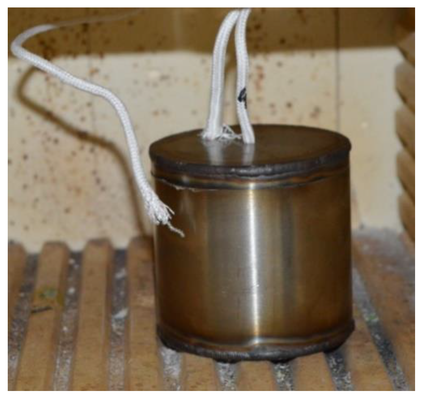
Several containers in AISI 304 stainless steel were manufactured. Two models of cylindrical containers were designed, one 50 mm high, 43 mm in diameter and 1.5 mm thick and the other 76 mm high, 76 mm in diameter and 1.5 mm thick. Both containers possessed two holes in the top cover, one located in the central area and the other between the central area and the outer edge. These holes were used to place the temperature control thermocouples and to fill in the container with PCM.
As lithium carbonate comes in powder form, the first step for its use was to melt it in order to deaerate it. The PCM filling was performed in several steps (filling, melting and refilling and melting until the PCM melted mass is obtained). To do this, small amounts of material were introduced into the container, as shown in
Figure 2, and then melted at 750 °C so that the material compacts and eliminates the air; then, more PCM powder was added and melted. This operation was carried out as many times as necessary until the container was filled up with the required PCM mass, in this case 160.8 g. Then, the sample was ready for the thermal stability test.
The location of the high-temperature “K”-type thermocouples in the device is shown in
Figure 3. The temperature in the center and side of the container as well as the outside temperature (oven temperature) were recorded every second for a greater control of the process.
Figure 4 shows the assembly of the test in muffle.
- -
Corrosion test to check the compatibility of the PCM with different steels for the container.
After the stability against thermal cycles test, the containers were cut to see whether there had been corrosion in the container material (stainless steel) that could have damaged it.
Given the importance of selecting a container material resistant to contact with carbonates at high temperature, a corrosion test was run for two stainless steels, AISI 304 and AISI 310. The test consisted of immersing specimens of stainless steel in Li2CO3 at 800 °C.
For this purpose, specimens of 80 mm × 15 mm in metal sheet (AISI 304 and AISI 310, respectively) were prepared. These were immersed for 240 h at 800 °C in Li2CO3, after which they were evaluated under an optical microscope (NIKON brand, EPIPHOT model). Additionally, a chemical analysis of the oxide layers was performed using the X-ray energy dispersion spectrometry technique “EDS” (brand JEOL, model JSM 5900LV).
3. Results
In this section, the results obtained from three test blocks will be discussed:
- (a)
Thermal characterization of PCM (DSC/TGA).
- (b)
Thermal stability of PCM in a container (thermal cycles).
- (c)
Corrosion analysis of the container.
- (a)
Thermal characterization of PCM (DSC/TGA)
Initially, a thermal characterization (DSC/TGA) of the PCM was carried out.
Figure 5 and
Figure 6 show the melting and crystallization curves of the PCM, as well as the curve of mass loss as a function of temperature.
In
Figure 5, the heating stage of the PCM is presented up to 750 °C. The blue curve shows the melting point of the PCM as well as the fusion enthalpy corresponding to the area under the curve. The sample has a melting point at 717.14 °C and its enthalpy is 487.2 J/g, data like those observed in the product data sheet and in the bibliography [
18]. Therefore, the values for melting enthalpy and melting temperature of lithium carbonate are confirmed. Nevertheless, the green curve, which represents the sample’s weight variation with temperature, shows a slight material loss (around 1.98%) at the melting temperature. This means that the material has suffered a small degradation at a lower temperature than its decomposition temperature (1310 °C). This data should be corroborated with the crystallization curve by checking that the enthalpy in the two processes, melting and crystallization, presents similar values.
The brown curve corresponds to the weight derivative. This curve represents the PCM’s mass variation rate over time when it is subjected to a temperature sweep.
Figure 6 shows the PCM crystallization during the cooling process. A crystallization of all the material is observed. Despite the small degradation observed, it is found that the PCM crystallization during the cooling process is complete, and there is no decrease in the value of the enthalpy. It shows that there has been no degradation of the PCM.
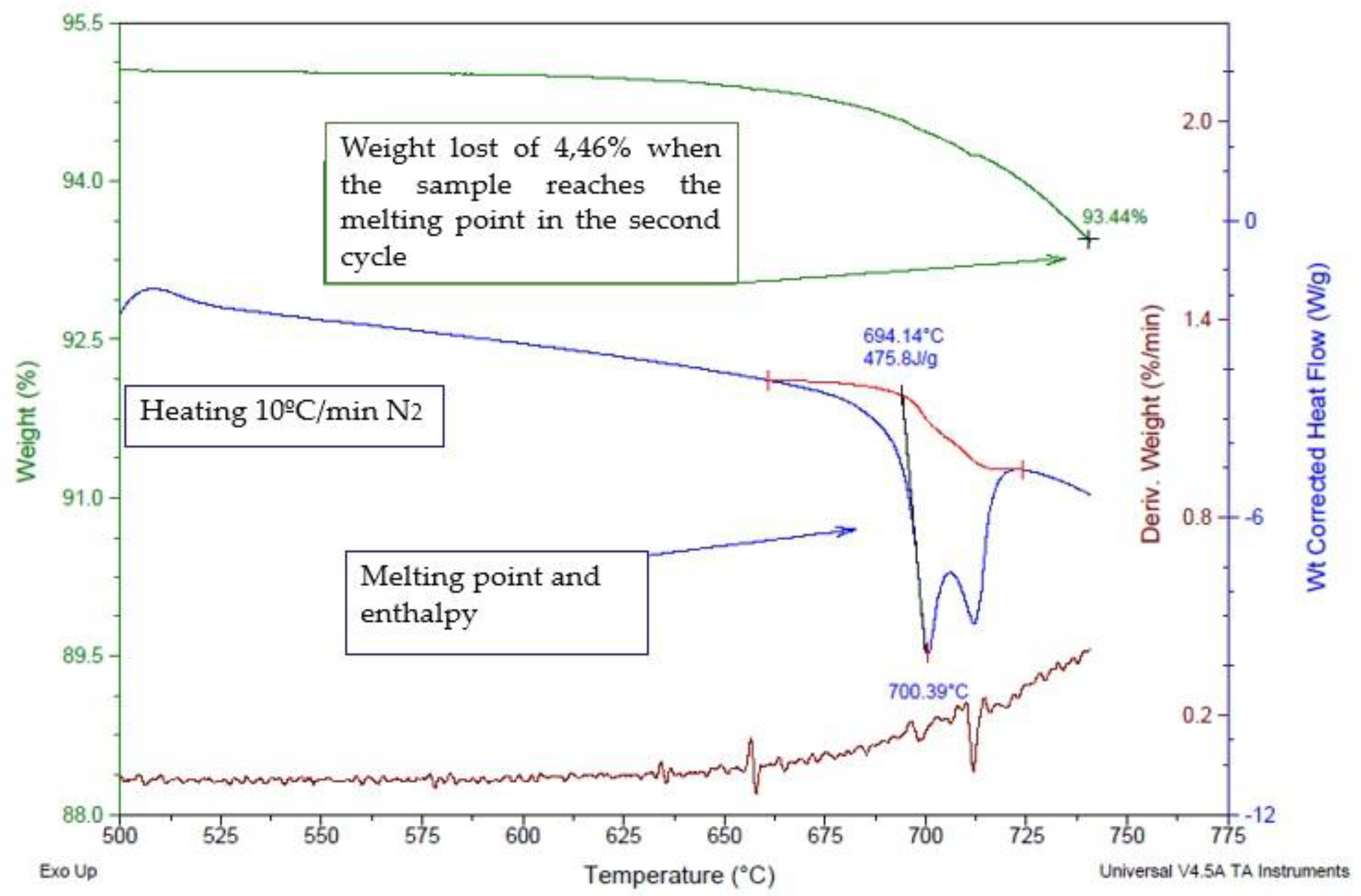
When carrying out a second heating test (
Figure 7) on the sample, it seems that it undergoes a degradation of 4.46% in its mass. The material decomposition temperature (lithium carbonate) is 1310 °C, but this effect seems to occur at lower temperatures, close to the melting point. As this effect does not correspond to the PCM data sheet, it is necessary to verify whether this degradation affects the PCM thermal properties after being subjected to several thermal cycles.
- (b)
Thermal stability of PCM in a container (thermal cycles)
After characterizing the properties of the PCM, its thermal stability is analyzed against heating cycles. This analysis is carried out in a 50 mm height, 43 mm diameter and 1.5 mm wall thickness AISI 310 cylindrical container. The lithium carbonate mass inside the container is 160.8 g.
Figure 8 shows the temperatures of the PCM as a function of time after carrying out six thermal cycles in the muffle, within the range of 580 to 800 °C. Each cycle consists of three stages: a heating-up stage (I), followed by an 800 °C constant temperature stage (II) and finally a cooling-down stage (III).
The repetitive thermal behavior of the PCM in all the cycles (
Figure 8) shows that the PCM does not undergo any significant degradation.
The melting plateau indicated in the graph shows that the PCM is capable of absorbing thermal peaks (261 W) around 725 °C for 5 min before its complete melting. The crystallization plateau, around 713 °C, shows a complete PCM recovery.
Figure 8 shows that the crystallization temperature is lower than the melting temperature; this is what is called a “subcooling effect”. Due to this subcooling effect, it must be ensured that the application has a minimum temperature below this crystallization temperature to ensure the PCM cyclic behavior. In this particular case, the nominal temperature of the exhaust gases is 700 °C, just below the crystallization temperature (713 °C), which guarantees the PCM’s cyclic behavior and therefore, its suitability for the application.
The thermoelectric device of this application works in a 700 °C environment, converting thermal energy into electrical energy. The device may be damaged by temperature peaks above its maximum value of 750 °C, as shown in
Figure 9a.
Figure 9b shows how the PCM protects the thermoelectric device against these temperature peaks. When the temperature peak occurs, the PCM absorbs heat and melts, keeping its temperature constant at its melting temperature (717 °C), so that the thermoelectric device is maintained at a temperature less than or equal to 717 °C (lower than its maximum value of 750 °C). The protection time against temperature peaks will depend on the PCM mass, which in turns depends on the application operation.
After carrying out the stability test, the container was weighed again to check if there had been loss of PCM mass. In this case, the mass after the test is 159.3 g. The loss of mass is 0.9% compared to the 4.46% loss observed in the DSC/TGA thermal analysis. This difference may be due to superficial degradation of the PCM, which can be significant when using small samples such as those used in the DSC/TGA thermal analysis (8.8 mg, where almost all the mass is exposed to the atmosphere). It is concluded that in the stability tests there was no significant mass degradation of the PCM.
- (c)
Corrosion analysis of the container
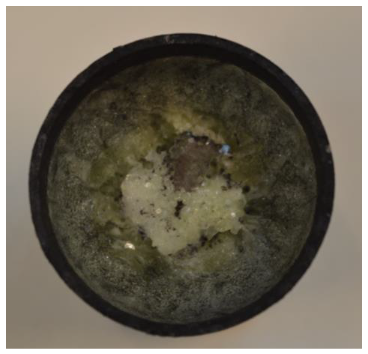
After the test, the containers were cut to see whether there had been corrosion in the container material, stainless steel, that could have damaged it.
As shown in
Figure 10, a greenish coloration appeared on the PCM’s surface, which may be due to a degradation of the stainless-steel container forming chromium oxide.
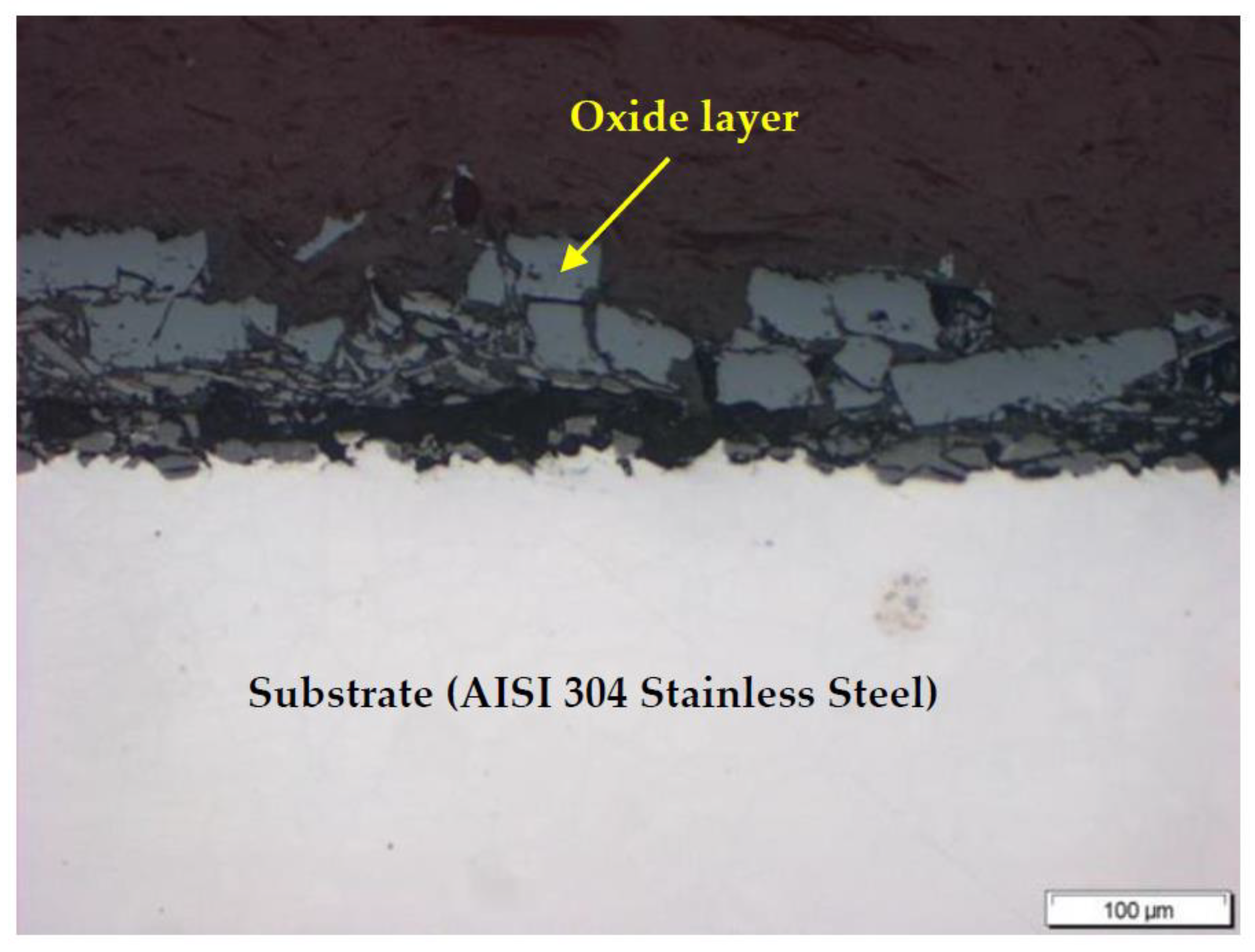
To verify this, a micrographic analysis was carried out. This analysis consists of the container cutting and its embedding in a resin for later observation in an optical microscope (NIKON brand, EPIPHOT model).
Figure 11 shows a micrograph of the oxide layer present in the AISI 304 container after the muffle tests. It presents a 100 μm-thick, non-homogeneous and without continuity layer, which is detached in fragments. This indicates that the material used as a container (AISI 304 stainless steel) has been affected by its contact with the PCM (lithium carbonate).
Given the importance of selecting a container material resistant to contact with carbonates at high temperature, a corrosion test was run for two stainless steels, AISI 304 and AISI 310, whose chemical compositions are listed in
Table 2. The test consisted of immersing the stainless steel in Li
2CO
3 at 800 °C.
Specimens of 80 mm × 15 mm in metal sheet (AISI 304 and AISI 310, respectively) were prepared. These were immersed for 240 h at 800 °C in Li
2CO
3,
Figure 12, after which they were evaluated under an optical microscope.
The thickness, continuity and homogeneity of the oxide layer were the parameters evaluated in each sample.
Figure 13 and
Figure 14 show the micrographs taken in the optical microscope of the oxide layers formed in the specimens of AISI 304 and AISI 310.
Figure 13 shows the oxide layer corresponding to the AISI 304 specimen. It is a 56 μm-thick and not very homogeneous layer with areas where it has completely detached. However, the oxide layer in the specimen of AISI 310 (
Figure 14) is homogeneous and continuous, which favors the substrate protection against corrosion under the test conditions.
Then, a chemical analysis of the oxide layers was performed using the X-ray energy dispersion spectrometry technique “EDS”.
Figure 15 and
Figure 16 show the analyzed oxide layer, indicated between yellow bars. The results are presented in
Table 3.
Table 3 shows the percentages in atomic weight of the main elements of the oxide layer present in both steels.
As can be seen, the percentages of Cr and Ni in the AISI 310 oxide layer are greater than those of the AISI 304. These high percentages of Cr and Ni favor the homogeneity and continuity of the oxide layer, avoiding its detachment and improving the steel’s protection against high-temperature corrosion [
20,
21]. The technique used does not allow us to analyze the content of Li due to its low atomic weight. However, this element is also present in the oxide layer, as noted by other authors [
19].
4. Conclusions
To protect the high-temperature (700–800 °C) thermoelectric converter from the temperature fluctuations, a thermal absorbent based on PCM is needed. From the possible PCMs, the lithium carbonate, Li2CO3, is selected as the most appropriate, as it theoretically fulfils the application requirements of high melting temperature and high melting enthalpy. The lithium carbonate thermal characterization tests confirm these high values, of 717.14 °C melting temperature and 487.2 J/g melting enthalpy.
The thermal cycle tests (heating, constant temperature and cooling) show a repetitive PCM thermal behavior at variations of high temperature, making it stable over time. Despite the subcooling effect of lithium carbonate, it is suitable for the application under study since the crystallization temperature (713 °C) is above the nominal temperature of the exhaust gas (700 °C), which ensures the cyclic behavior.
In terms of durability or corrosion resistance of the metal container, corrosion tests show that the AISI 310 stainless steel has greater resistance than the AISI 304. The oxide layer generated on the AISI 310 surface is more homogeneous and continuous than that of the AISI 304, which avoids its detachment and improves the steel’s protection against high-temperature corrosion. Despite these results, a long-term study is necessary to confirm the corrosion resistance of AISI 310 by lithium carbonate.
Thus, from this work it is concluded that AISI 310, as the container material, and lithium carbonate, as the PCM, are an interesting combination of materials in the design of thermal absorbers for high-temperature (700–800 °C) thermoelectric conversion.


