Article

Improving a Rapid Alignment Method of Tomography Projections by a Parallel Approach

1
Elettra—Sincrotrone Trieste, Strada Statale 14, km 163.5 in Area Science Park I-34149 Basovizza, 34149 Trieste, Italy
2
Image Processing Laboratory (IPL), Engineering and Architecture Department, University of Trieste, Via A.Valerio 10, 34127 Trieste, Italy
3
Institute for Maternal and Child Health, IRCCS Burlo Garofolo, Via dell’Istria 65/1, 34137 Trieste, Italy
4
ALBA Synchrotron Light Source, Carrer de la Llum 2-26, 08290 Cerdanyola del Vallès, Spain
*
Author to whom correspondence should be addressed.
Appl. Sci. 2021, 11(16), 7598; https://doi.org/10.3390/app11167598
Submission received: 19 July 2021 / Revised: 14 August 2021 / Accepted: 17 August 2021 / Published: 18 August 2021
(This article belongs to the Special Issue X-ray Medical and Biological Imaging)

Abstract

:

Featured Application

Cryo-nano tomography of biological samples with no landmarks in view.

Abstract

The high resolution of synchrotron cryo-nano tomography can be easily undermined by setup instabilities and sample stage deficiencies such as runout or backlash. At the cost of limiting the sample visibility, especially in the case of bio-specimens, high contrast nano-beads are often added to the solution to provide a set of landmarks for a manual alignment. However, the spatial distribution of these reference points within the sample is difficult to control, resulting in many datasets without a sufficient amount of such critical features for tracking. Fast automatic methods based on tomography consistency are thus desirable, especially for biological samples, where regular, high contrast features can be scarce. Current off-the-shelf implementations of such classes of algorithms are slow if used on a real-world high-resolution dataset. In this paper, we present a fast implementation of a consistency-based alignment algorithm especially tailored to a multi-GPU system. Our implementation is released as open-source.

1. Introduction

Soft X-ray cryo-nano tomography is an effective imaging tool that allows one to analyse biological samples in their native environment, providing ultrastructural three-dimensional information of cells [1]; indeed, the high resolution of this technique, typically in the tens of nanometres [2], is paired not only to a profitable contrast behaviour in a specific range of energy, the water window, but also permits imaging in the hydrated state without staining, as the sample preparation requires only vitrification of water via a cryo-fixation process [3]. Phase contrast techniques [4] are especially used in the hard-X-ray regime, as the contrast due to phase shift is typically three orders of magnitude larger than the corresponding absorption [4].
To obtain a reconstruction from a series of 2D projections, tomography relies on a corpus of a priori information which constitutes an image formation model [5]. In its simplest form, the rotation axis is fixed in the 3D space, and its 2D projection lays in the central column (or row) of the detector, which is also fixed and locked to the source; a pure rotation is what describes the relative motion of the sample with respect to the detector.

1.1. Projection Misalignment Problem

If any of the previous assumptions is not met, a dataset acquired under these conditions is defined as misaligned, and exploiting the ideal model introduced earlier produces several artefacts in the reconstruction. While for a constant systematic error [6] the misalignment can be corrected by a relatively easy determination of the rotation centre [7,8] (this can be typically sufficient for µ-CT, e.g., in [9]), the mechanical imperfections of the setup become clearly detectable, especially at the nanoscale [10]: temperature-dependent asynchronous errors [6] can be unpredictable for each projection angle. The physical cause of this issue is due to backlash and non-constant roundness in the bearings used for the sample stage, leading to eccentricity [11], runout, or spindle errors [2,6,12]. At the detector, the main observable effect of these misalignments is a jitter in x , y [12,13], which are the coordinate axes of the detector. Without proper correction, a dataset acquired under these circumstances is completely unusable, as a severe point spread function [14] is introduced in the reconstruction, jointly with a peculiar artefact [13]. Even if in some cases the error component can be measured and corrected [15] (also with interferometric encoding of the specimen position [11]), this is not the case of special setups, such as the one employing cryo-stages [12,16], for which even more advanced opto-mechanical outbreaks than the ones described in [17] are required to reach a sub-10 nm resolution. Post-acquisition alignment is thus usually necessary [12].

1.2. Post-Acquisition Alignment

Marker-based alignment methods are a common solution to the problem, especially in the case of biological samples which exhibit low absorption contrast and/or not well-defined features; at the cost of decreasing the sample visibility (this is the measure of how critical this step is), gold nano-beads are added to the sample solutions before cryo-fixation [2] and are tracked in a post-acquisition procedure among each projection. IMOD [18,19,20] and many other software frameworks [14,21,22,23,24,25,26] reviewed in, e.g., [27] are used to manage this delicate pre-processing step. However, this approach is questionable, as for many biological specimens, it is extremely difficult to control the spatial distribution of such fiducials. Large areas of the sample can be completely void of markers, or, conversely, the distribution can be so dense that many different beads agglomerate one to another, determining no reliable tracking information. Automatic feature-based approaches are proven to work only in the presence of high quality images [28].
Tomography self-consistency or bootstrap methods [29,30] instead try to infer the alignment parameters while reconstructing the volume (Section 2). Paired with coarse alignment [31], these methods are usually the best choice to solve the misalignment problem. While in great part automatic, these techniques are for their nature extremely demanding from a computational point of view and can require both commercial software and highly experienced users [16]. The rapid projection alignment method presented in [12] belongs to this class of algorithms, is implemented in the advanced Tomopy [7] software framework, and can be simply introduced in the pipeline by just invoking one line of code. Unfortunately, the implementation can be slow on high-resolution datasets such as the one acquired with newer setups [4], undermining its use as a fast method.

1.3. Proposed Solution

Here, we propose a solution to improve the speed of the algorithm [12] by an order of magnitude by extensively exploiting the parallel approach in the entire processing pipeline. The algorithm is structured with a modular approach, allowing us to separately use each accelerated component (e.g., the tomography reconstruction/synthesis module) through an API. The proposed solution which is tailored for parallel beam geometry has also been implemented on a multi-GPU system and is tested against a multi-GPU-ready version of Tomopy. In Section 2, the method is described, while Section 3 presents the results by showing the acceleration capability for each module. Our software (provided as open source at [32]) has been tested on artificially misaligned µ-CT data but also on a real high-resolution dataset acquired at MISTRAL, the soft X-ray transmission microscopy beamline at the ALBA synchrotron light source (Barcelona, Spain) [1,2,3].

2. Computational Methods

The main idea of reconstruction “self-consistency” [33] is that at the convergence, from a reconstructed volume, one can simulate a set of projections which are virtually indistinguishable from the original dataset. This is exactly what is sought during a reconstruction in a deterministic iterative algorithm (MSE based) [5,13,34].
The setup parameters Θ may be made to concur with the object x to reduce the total reconstruction error; this is a recurring theme in many computational imaging techniques (e.g., in [28,34]). Indeed, in [13], an optimisation problem is cast involving the 2D detector offset and tilt for each projection. At the cost of increased complexity, more complete correction can be employed in the algorithms as described in [16,33].

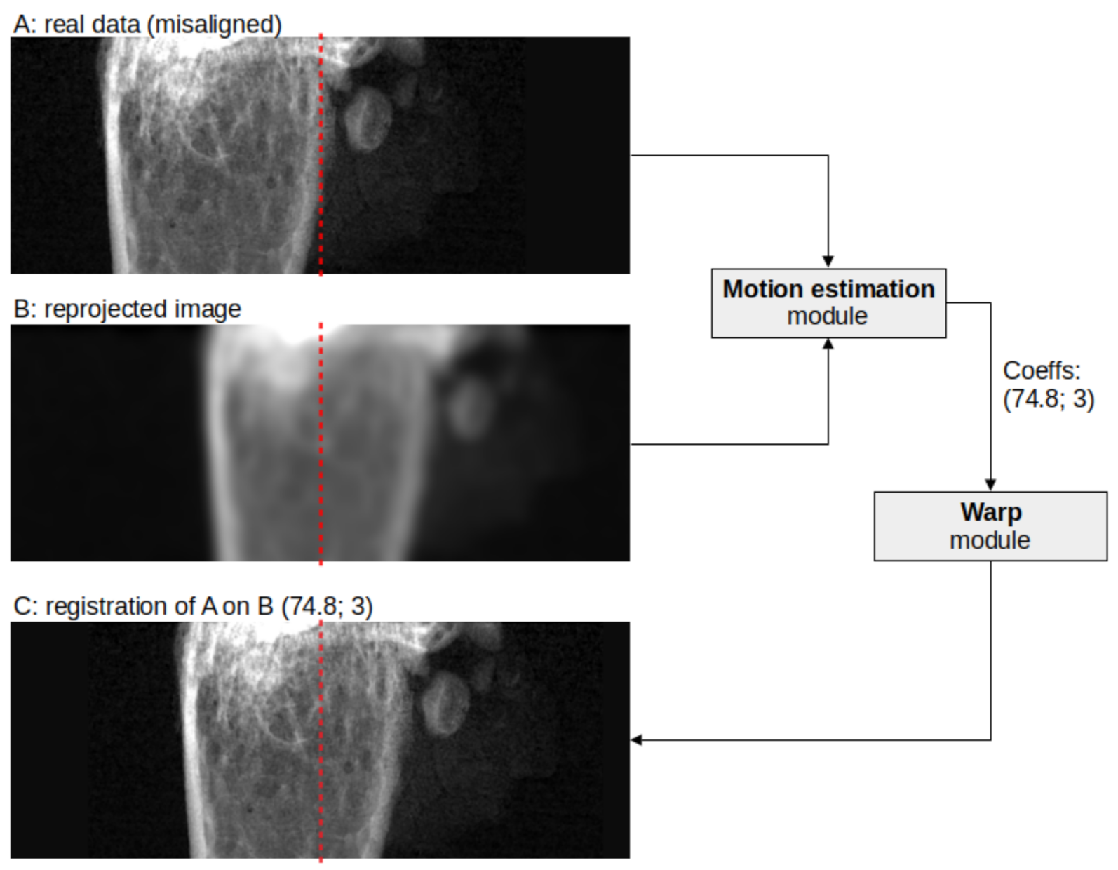
2.1. Joint Reconstruction-Reprojection Method

Including many parameters directly within the optimisation pool can sometimes be detrimental, as the solution space is filled with local minima (the curse of dimensionality [35]), where the solution may stagnate [36].
When only the detector shift parameters are of interest [12], a different path is possible [29]: after having reconstructed an object with a conventional algorithm, a set of synthetic projections is generated by employing the reconstructed volume; these reprojections are then registered with the actual tomography dataset (Figure 1). The procedure is iterated until the shift parameters are nullified. The actual alignment is retrieved by using the phase-correlation [37] as a meaningful similarity metric for the two sets.

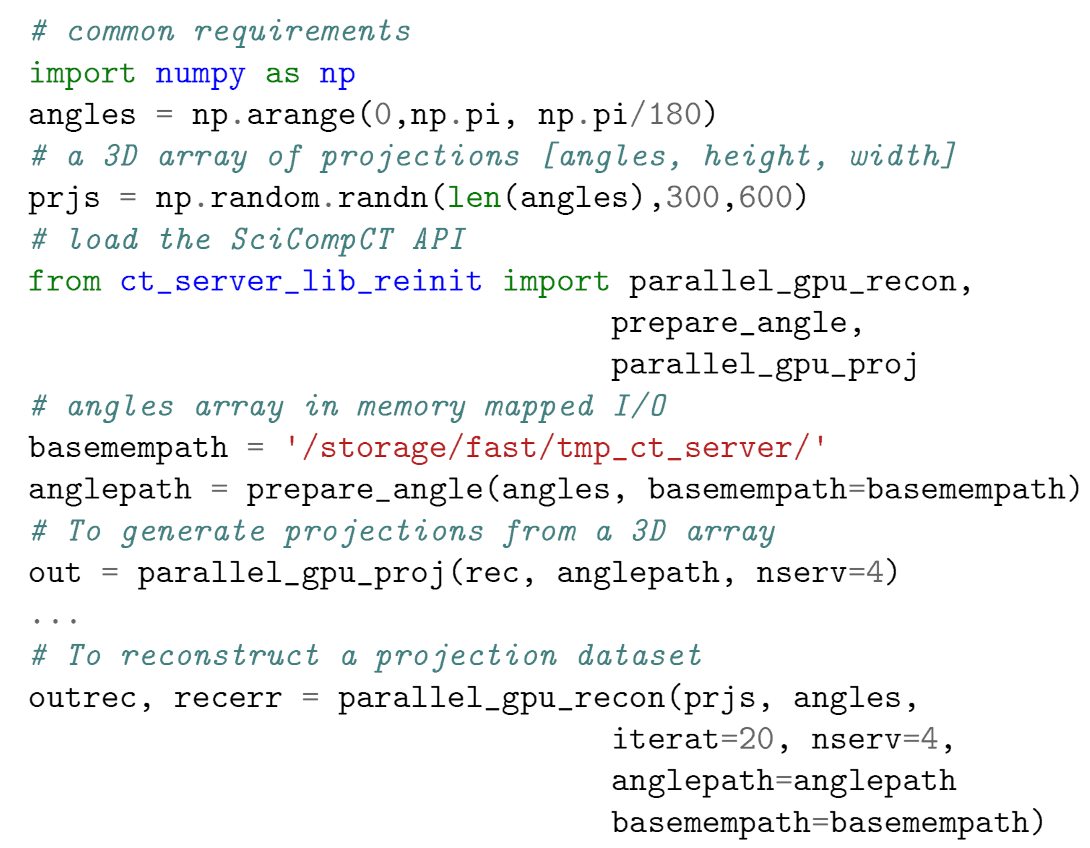
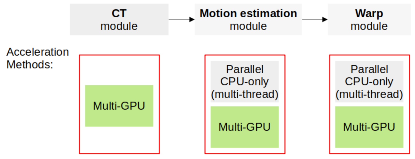
2.2. Implementation Details

In recent times, faster execution of an algorithm is mainly achieved not by increasing the performance per processing unit, but by enlarging the number of executioners [38,39,40]. In a highly parallelisable problem such as parallel-beam tomography [41], the typical approach consists of exploiting the inherent data parallelism [40], meaning that the whole computation can be divided into many smaller problems which can be solved concurrently [38]. Not all computational imaging techniques are so blessed. Massively parallel accelerators such as GPUs are currently extensively used, thanks to a plethora of GPU-ready available algorithms (e.g., [42,43,44]) that in turn are implemented in several reconstruction frameworks such as [7,42,45].
From the analysis of the alignment algorithm [12], we detected three main areas for the global acceleration (Figure 2): (1) a tomography reconstruction and projection component is required to gather the volume estimate and the synthetic projections; (2) a motion estimation procedure is employed to check for the registration parameters; and (3) a warp interpolator is used to generate the new registered dataset. While for the two latter modules we also studied a CPU-only parallel solution (Figure 2), for the CT component, it was already clear that a GPU implementation would have been the only viable option.
In this work, we deconstructed the algorithm by implementing each step with a highly parallelised version of each computational block; this is crucial to utilise all the computational resources at hand. The result is a modular structure that can be used to solve not only the tomography alignment problem as a whole, but each module can be used separately in any image-processing pipeline (e.g., Hough transform for pattern matching and computer vision applications, image registration, etc.).

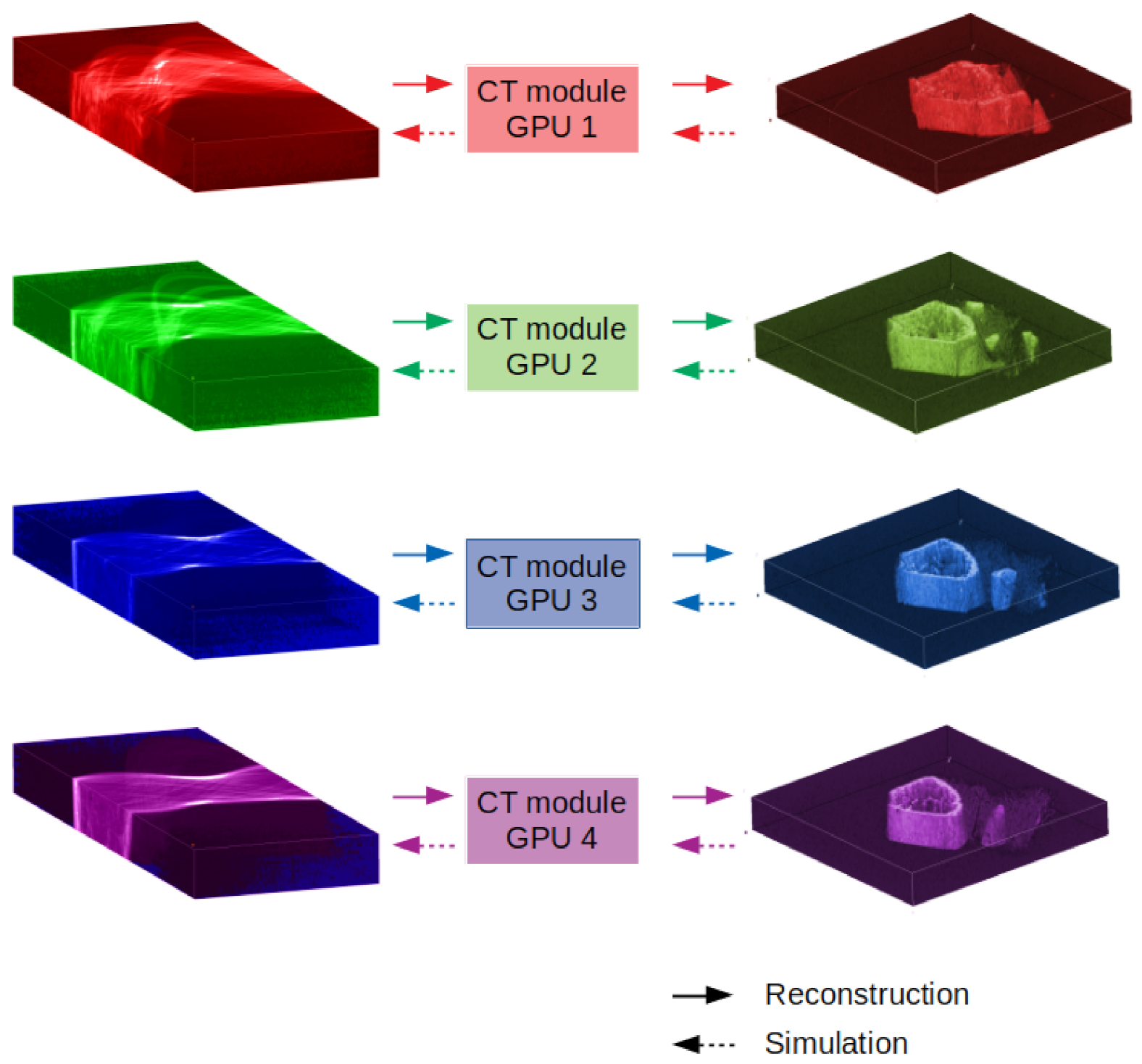
2.3. Tomography Module

Even if in the literature several multi-GPU algorithms are proposed [45,46,47,48,49,50], off-the-shelf, ready-to-be-used alternatives are currently scarce. This is especially true for iterative algorithms such as SIRT [51] which are essential in the case of cryo-nano tomography, as both the missing wedge problem [52] and the angle under-sampling can be severe. We released a simplistic but effective CT module (Figure 3) that allows the distribution of both the tomography forward and backward operators among n GPUs. The custom implementation is realised on top of the advanced ASTRA Toolbox framework [13,42] and consists of n CT servers which are configured to accept commands from an easy-to-use Python API; the API automatically slices the dataset in n portions along the row axis and uses a memory mapped array for the entire data scattering procedure, and each portion is processed concurrently. The results of each executer are gathered and finally composed on the row axis to produce the entire output (Figure 3). Through the ASTRA Toolbox, two 3D iterative reconstruction algorithms are available: SIRT3D_CUDA and CGLS3D_CUDA.

2.4. Motion Estimation Module

As said before, a similarity metric is required to estimate the registration parameters. Even if an iterative alignment algorithm has been initially taken into consideration [53], a one-shot procedure such as phase-correlation is desirable as a component of a fast method; for each iteration, only three DFTs and an element-wise multiplication are required, at least for its coarse-scale version. DFTs are surely expensive operations, but accelerated algorithms are currently pervasive. Still, sub-pixel information is crucial, as hundreds of iterations of the entire algorithm [12] are likely to be performed: the procedure indeed cumulates the story of the shift to producing the current registration value to warp the dataset. In this way, the frame information is not progressively lost iteration by iteration due to padding. The use of the particular methodology presented in [37] is thus essential to obtain at a reasonable speed for this fine-grained information.
The motion estimation procedure is carried out on each projection pair (acquired, synthesised); thus, this entire computational block can be implemented again with the data parallelism concepts in mind by splitting the whole problem as per-angle sub-procedures. We thus implemented two different pathways to achieve the algorithm acceleration: an accelerated CPU-only version is written by encapsulating the implementation of [37] already present in Scikit-Image [54] in a multi-threaded pipeline. The second solution instead consists of writing the sub-pixel phase correlation algorithm [37] in PyTorch [55], which here is used not as a deep learning tool but as an easy path for GPU programming. Similar to the previous case, a dispatcher splits the problem on n GPUs for concurrent execution. As it will be shown in Section 3, the acceleration is large even in the case of the CPU-only multi-threaded solution.

2.5. Warp Module

The warp module is used to transform the dataset applying an affine transform on each projection. As the problem can again be split into several independent problems, we can accelerate the algorithm both by moving the computation to the GPU and exploiting the data parallelism concept; the tuple composed of (projection, parameters) thus represents the input for each subroutine, which is automatically dispatched among the available executioners, which can be CPU cores or GPU cards. The GPU implementation is written in the PyTorch Python dialect and makes use of a parametrisable grid generator and grid sampler, which are the essential components initially developed for the 2D interpolator of a spatial transformer network [56]. In the results section, we will discuss the effects of the data transfer to the GPU.

3. Results and Discussion

To measure the algorithm acceleration, we benchmarked each module against the corresponding block in the algorithm implementation [12] in Tomopy [7]. The system used for the testing is an HPC node, whose hardware and software configuration is summarised in Table 1.
Reconstruction Baseline
While initially Tomopy offered GPU reconstruction algorithms solely through interfaces [47,50] to a single-GPU solution, in a very recent version, a native 3D multi-GPU reconstruction algorithm can be invoked during the alignment procedure. However, no other parts of the algorithm are currently parallelised. The recent scenario represents the baseline configuration we used in our manuscript.
Observation Variables
To verify the working principle of our method, it is crucial to check for a reduction in the execution time of each step of the proposed algorithm; this is done trough benchmarks. As we mentioned, to generate an aligned dataset, the procedure requires the steps described in Section 2 (see Figure 2: the reconstruction, the motion estimation, and the frame warp. That is why this section is divided into (1) “CT module benchmark”; (2) “Motion estimation benchmark”; and finally, (3) “Warp Module benchmark”. Due to the complexity of the inner working, as the CT module will be difficult to use by calling the RAW functions, an easy-to-import API has been written to ease the import into a custom code; a test code will be presented.
If no further processing is required (e.g., beads removal, deconvolution, etc.), eventually the reconstruction generated by the method (as a by-product of the alignment procedure) can be considered final.
As we are devoted primarily to the speed of execution and considering that our implementation is working in a numerically accurate manner that follows the original algorithm [12], our results are mainly based on speed comparisons only.

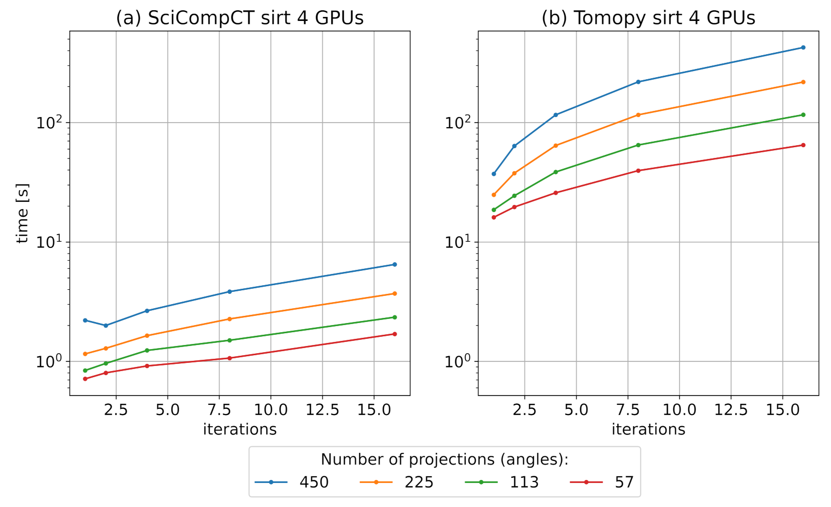
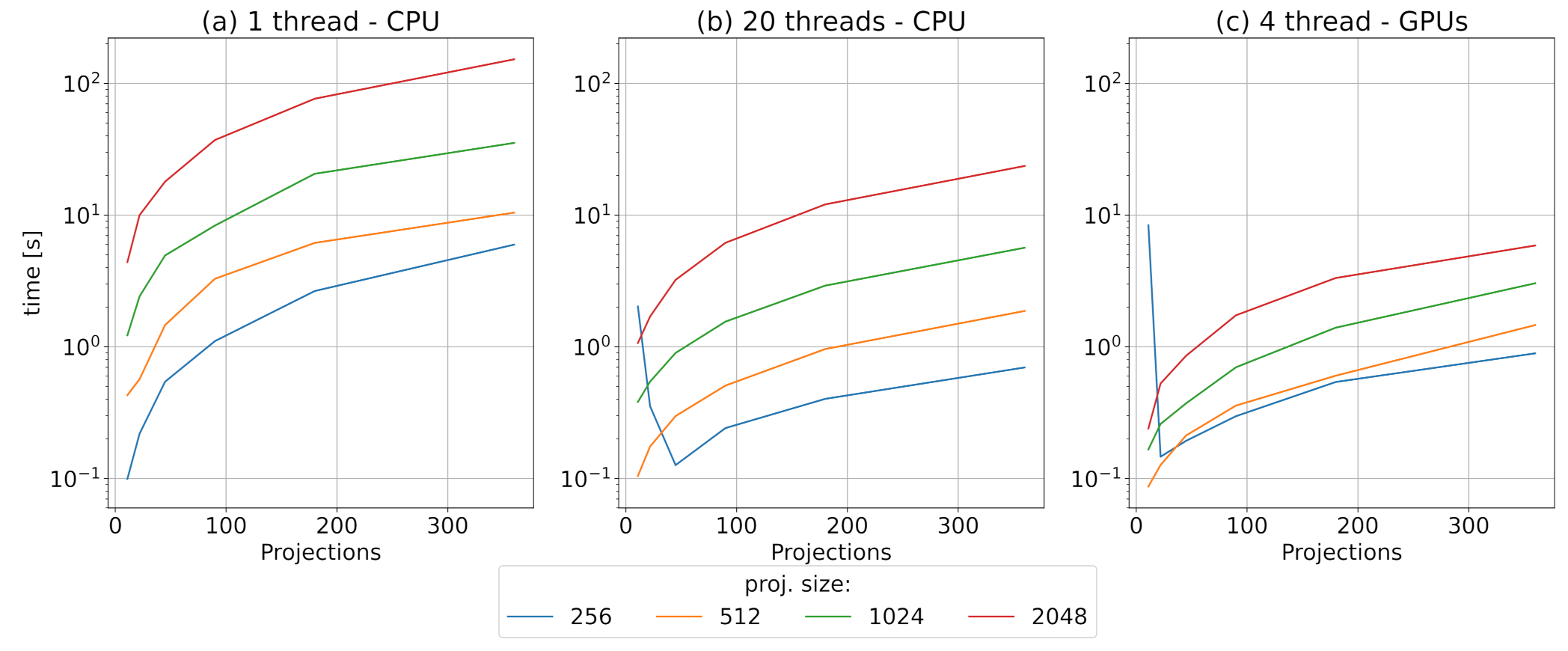
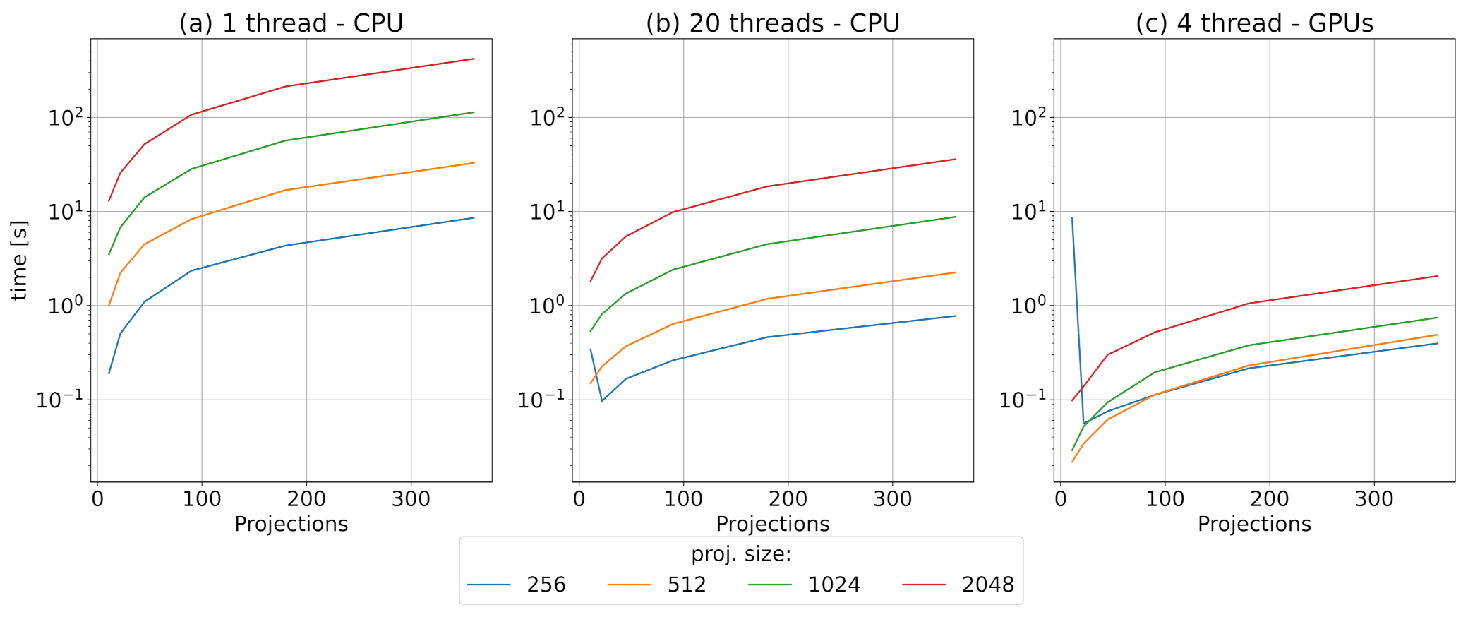
3.1. CT Module Benchmark

Figure 4 shows the speed performance of the proposed solution (panel a) tested against the reference Tomopy multi-GPU setup (panel b). We reconstructed a set of projections with size 1024 × 1024 each; each curve represents the time required to reconstruct a dataset with 57, 113, 225, or 450 angles and thus the same number of images. By looking at the highest number of angles (blue curve), it can be seen how the proposed solution is faster by a factor close to one order of magnitude.
As our solution is modular, it has to be noted that our parallel CT module can be used as a stand-alone program which uses n GPUs. To embed it in a custom code is quite straightforward: with the CT servers running (Section 2), a simple API can be called within a Python program, such as shown in Listing 1.

3.2. Motion Estimation Module Benchmark

The motion estimation module has been tested by varying the number of projections in the dataset (x-axis on each panel of Figure 5), parametrising the curve on the size of each projection image. Considering the baseline configuration (panel a), the performance gain is still large even for the multi-thread and CPU-only solution (panel b), but it can be improved even further by dispatching the load on the four GPUs (panel c). In the present case, we can effectively measure a speed improvement by switching towards a GPU computation only due to the fact that the actual computation is effectively computationally intensive (DFTs, elementwise multiplications, and matrix multiplications [37,54]) and parallelisable [38], despite the additional latency that is introduced in the system by moving large arrays from the central memory to the GPU RAM.

3.3. Warp Module Benchmark

Figure 6 shows the speed gain that can be obtained by accelerating the warping procedure. Similar to the previous case, panel a shows the baseline configuration, while panels b and c show, respectively, the speed of a parallel CPU-only implementation and the multi-GPU approach. Here the latency associated with the GPU implementation is even larger, due to the results gathering; indeed, this operation involves the copy of the results from the GPU to the main memory. Despite this, we can still measure a considerable performance gain, as the computation of an affine transform is again computationally intensive, especially for a large number of high-resolution projections.

3.4. Entire Algorithm Test

To test for the algorithm working, we used an old µ-CT dataset acquired at the Syrmep beamline of the Elettra synchrotron facility [9,21]. The CCD resolution of each image is of 600 × 300 pixels, and the dataset contains 450 projections of a mouse femur that span a [0, 180 ] angular range, acquired with a parallel-beam setup. To simulate the misalignment, we added a random x , y jitter in each projection with a standard deviation of 10 pixels, obtaining a severely misaligned dataset, as can be seen in Figure 7 panel a; the use of the alignment algorithm allows correcting for the jitter, producing the aligned dataset in panel b. An off-axis feature seems completely missed in panel (a), but it is simply faint; by using the alignment procedure, it becomes quite evident within the sinogram.

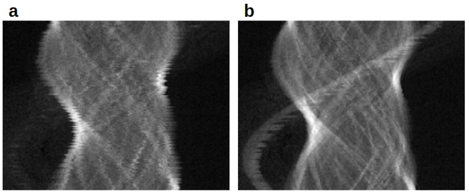
3.5. Nanotomography Data

Figure 8 shows a real cryo-nano tomography dataset acquired at the MISTRAL beamline of the ALBA synchrotron facility; a biological sample of eukaryotic cell debris has been cryo-fixated on a gold grid and imaged at 900 eV [2]. Although the condenser optics of the soft X-ray microscope focuses the beam onto the sample, it is typical for this setup to assume a simplified geometry with an incoming parallel beam [1,2]. The objective Fresnel zone plate lens (FZP) collects the transmitted beam, producing a magnified image (×1000) at the back-illuminated CCD detector (Princeton Pixis XO, pixel size of 13 µm) [2]. The resulting dataset is a set of 121 images, acquired at a resolution of 1024 × 1024 pixels and at an angle of [−60 , 60 ]. The rotation run-out is about 300 nm, which is currently the state of the art [2], but due to the extremely complex setup and the large magnification factor (effective pixel size of 13 nm), a severe misalignment problem is inevitably present (Section 1). As can be seen in panel a, the sinogram of a particular off-axis feature is extremely jittered, and no “sine” can be recognized. Conversely, in panel b, the alignment makes it heavily pronounced. The effect of the correction is more evident at the border by observing how each line is shifted along the axis; the black part is the result of the padding operation, whose effects are reduced by employing a shift-cumulation procedure. The alignment process in Figure 8 has been performed by exploiting a multi-scale approach, aligning the dataset iteratively at a different scale. The reconstruction is re-initialised after each change of scale and starts by employing the set of projections aligned at the previous one. This kind of correction is completely unfeasible on the reference software configuration, as the required time would have increased even further.

4. Conclusions

In this paper, we proposed a modular framework for (nano)tomography alignment. Often, in biological samples, regular, high-contrast features can be scarce, and this represents a problem if nano-beads are also not in view. If no robust trackable features are present, the dataset is useless. Thus, an automatic alignment algorithm, such as the bootstrap method, becomes extremely useful. A well-known and well-performing CT bootstrap-based algorithm [12] has been analysed and deconstructed to isolate and determine its three essential components. This algorithm provides good results, but it can be slow, as its implementation is sequential and CPU-based. The entire algorithm has then been re-implemented: the modular approach we designed allows us to adapt the parallelisation paradigms both for a multi-thread CPU implementation and a multi-GPU solution. As a result, the entire algorithm is globally accelerated. For each module, the benchmarks reported a performance gain that is close to one order of magnitude, allowing for a rapid correction on high-resolution datasets. The correction can be even more accurate, as a multi-scale approach is now feasible. The software is released as open-source and can be downloaded from [32]. Thanks to its modular structure, each component can eventually be incorporated easily in a custom code. As a by-product, we provide “SciCompCT”, a ready-to-be-used solution for a parallel beam multi-GPU SIRT algorithm. We believe that the proposed approach could be particularly useful for low-density matrices such as biological samples.

Author Contributions

Conceptualization, F.G., G.K., F.B., A.S. and S.C.; methodology, F.G., G.K. and S.C.; software, F.G.; validation, G.K., A.G., L.P., A.S., S.C. and F.B.; resources, F.B., G.K. and S.C.; data curation, A.G., L.P., F.G. and A.S. All authors participated in writing the manuscript. All authors have read and agreed to the published version of the manuscript.

Funding

This research has been partially developed under the Advanced Integrated Imaging Initiative (AI3), project P2017004, of Elettra Sincrotrone Trieste in agreement with the University of Trieste.

Institutional Review Board Statement

Not applicable.

Informed Consent Statement

Not applicable.

Data Availability Statement

The µ-CT dataset is available at [32].

Acknowledgments

The authors are thankful to Francesco Brun for the µ-CT dataset and to the System Administrators of the Elettra IT Group, in particular to Iztok Gregori for his work on the HPC solution. This research includes experiments that were performed at the MISTRAL beamline at ALBA Synchrotron (proposal number 2019023350) in collaboration with ALBA staff.

Conflicts of Interest

The authors declare no conflict of interest.

Abbreviations

The following abbreviations are used in this manuscript:
APIApplication Program Interface
CCDCharge Coupled Device
CPUCentral Processing Unit
CTComputed Tomography
DFTDiscrete Fourier Transform
GPUGraphics Processing Unit
HPCHigh Performance Computing
MSEMean Square Error
RAMRandom Access Memory
SIRTSimultaneous Iterative Reconstruction Technique
STNSpatial Transformer Network

References

  1. Pereiro, E.; Nicolás, J.; Ferrer, S.; Howells, M.R. A soft X-ray beamline for transmission X-ray microscopy at ALBA. J. Synchrotron Radiat. 2009, 16, 505–512. [Google Scholar] [CrossRef]
  2. Sorrentino, A.; Nicolás, J.; Valcárcel, R.; Chichón, F.J.; Rosanes, M.; Avila, J.; Tkachuk, A.; Irwin, J.; Ferrer, S.; Pereiro, E. MISTRAL: A transmission soft X-ray microscopy beamline for cryo nano-tomography of biological samples and magnetic domains imaging. J. Synchrotron Radiat. 2015, 22, 1112–1117. [Google Scholar] [CrossRef]
  3. Carrascosa, J.L.; Chichón, F.J.; Pereiro, E.; Rodríguez, M.J.; Fernández, J.J.; Esteban, M.; Heim, S.; Guttmann, P.; Schneider, G. Cryo-X-ray tomography of vaccinia virus membranes and inner compartments. J. Struct. Biol. 2009, 168, 234–239. [Google Scholar] [CrossRef]
  4. Arhatari, B.D.; Stevenson, A.W.; Abbey, B.; Nesterets, Y.I.; Maksimenko, A.; Hall, C.J.; Thompson, D.; Mayo, S.C.; Fiala, T.; Quiney, H.M.; et al. X-ray phase-contrast computed tomography for soft tissue imaging at the imaging and medical beamline (IMBL) of the australian synchrotron. Appl. Sci. 2021, 11, 4120. [Google Scholar] [CrossRef]
  5. Bertero, M.; Lantéri, H.; Zanni, L. Iterative image reconstruction: A point of view. Math. Methods Biomed. Imaging Intensity Modul. Radiat. Ther. (IMRT) 2008, 7, 37–63. [Google Scholar]
  6. Grejda, R.; Marsh, E.; Vallance, R. Techniques for calibrating spindles with nanometer error motion. Precis. Eng. 2005, 29, 113–123. [Google Scholar] [CrossRef] [Green Version]
  7. Gürsoy, D.; De Carlo, F.; Xiao, X.; Jacobsen, C. TomoPy: A framework for the analysis of synchrotron tomographic data. J. Synchrotron Radiat. 2014, 21, 1188–1193. [Google Scholar] [CrossRef] [PubMed] [Green Version]
  8. Yang, X.; De Carlo, F.; Phatak, C.; Gürsoy, D. A convolutional neural network approach to calibrating the rotation axis for X-ray computed tomography. J. Synchrotron Radiat. 2017, 24, 469–475. [Google Scholar] [CrossRef] [Green Version]
  9. Longo, R.; Arfelli, F.; Bonazza, D.; Bottigli, U.; Brombal, L.; Contillo, A.; Cova, M.A.; Delogu, P.; Di Lillo, F.; Di Trapani, V.; et al. Advancements towards the implementation of clinical phase-contrast breast computed tomography at Elettra. J. Synchrotron Radiat. 2019, 26, 1343–1353. [Google Scholar] [CrossRef] [PubMed] [Green Version]
  10. Yu, H.; Xia, S.; Wei, C.; Mao, Y.; Larsson, D.; Xiao, X.; Pianetta, P.; Yu, Y.S.; Liu, Y. Automatic projection image registration for nanoscale X-ray tomographic reconstruction. J. Synchrotron Radiat. 2018, 25, 1819–1826. [Google Scholar] [CrossRef] [PubMed] [Green Version]
  11. de Jonge, M.D.; Kingston, A.M.; Afshar, N.; Garrevoet, J.; Kirkham, R.; Ruben, G.; Myers, G.R.; Latham, S.J.; Howard, D.L.; Paterson, D.J.; et al. Spiral scanning X-ray fluorescence computed tomography. Opt. Express 2017, 25, 23424–23436. [Google Scholar] [CrossRef] [PubMed] [Green Version]
  12. Gürsoy, D.; Hong, Y.P.; He, K.; Hujsak, K.; Yoo, S.; Chen, S.; Li, Y.; Ge, M.; Miller, L.M.; Chu, Y.S.; et al. Rapid alignment of nanotomography data using joint iterative reconstruction and reprojection. Sci. Rep. 2017, 7, 11818. [Google Scholar] [CrossRef] [Green Version]
  13. van Aarle, W.; Palenstijn, W.J.; Cant, J.; Janssens, E.; Bleichrodt, F.; Dabravolski, A.; De Beenhouwer, J.; Joost Batenburg, K.; Sijbers, J. Fast and flexible X-ray tomography using the ASTRA toolbox. Opt. Express 2016, 24, 25129. [Google Scholar] [CrossRef]
  14. Han, R.; Wan, X.; Wang, Z.; Hao, Y.; Zhang, J.; Chen, Y.; Gao, X.; Liu, Z.; Ren, F.; Sun, F.; et al. AuTom: A novel automatic platform for electron tomography reconstruction. J. Struct. Biol. 2017, 199, 196–208. [Google Scholar] [CrossRef] [Green Version]
  15. Dehaeze, T.; Collette, C.; Magnin-Mattenet, M. Sample Stabilization for Tomography Experiments in Presence of Large Plant Uncertainty. In Proceedings of the 10th Mechanical Engineering Design of Synchrotron Radiation Equipment and Instrumentation, Paris, France, 25–29 June 2018. [Google Scholar]
  16. Odstrčil, M.; Holler, M.; Raabe, J.; Guizar-Sicairos, M. Alignment methods for nanotomography with deep subpixel accuracy. Opt. Express 2019, 27, 36637–36652. [Google Scholar] [CrossRef] [Green Version]
  17. De Andrade, V.; Nikitin, V.; Wojcik, M.; Deriy, A.; Bean, S.; Shu, D.; Mooney, T.; Peterson, K.; Kc, P.; Li, K.; et al. Fast X-ray Nanotomography with Sub-10 nm Resolution as a Powerful Imaging Tool for Nanotechnology and Energy Storage Applications. Adv. Mater. 2021, 33, 2008653. [Google Scholar] [CrossRef]
  18. Kremer, J.R.; Mastronarde, D.N.; McIntosh, J. Computer Visualization of Three-Dimensional Image Data Using IMOD. J. Struct. Biol. 1996, 116, 71–76. [Google Scholar] [CrossRef] [Green Version]
  19. Mastronarde, D.N.; Held, S.R. Automated tilt series alignment and tomographic reconstruction in IMOD. J. Struct. Biol. 2017, 197, 102–113. [Google Scholar] [CrossRef] [Green Version]
  20. Mastronarde, D.N. Dual-Axis Tomography: An Approach with Alignment Methods That Preserve Resolution. J. Struct. Biol. 1997, 120, 343–352. [Google Scholar] [CrossRef]
  21. Brun, F.; Pacilè, S.; Accardo, A.; Kourousias, G.; Dreossi, D.; Mancini, L.; Tromba, G.; Pugliese, R. Enhanced and Flexible Software Tools for X-ray Computed Tomography at the Italian Synchrotron Radiation Facility Elettra. Fundam. Inform. 2015, 141, 233–243. [Google Scholar] [CrossRef]
  22. Brun, F.; Massimi, L.; Fratini, M.; Dreossi, D.; Billé, F.; Accardo, A.; Pugliese, R.; Cedola, A. SYRMEP Tomo Project: A graphical user interface for customizing CT reconstruction workflows. Adv. Struct. Chem. Imaging 2017, 3, 4. [Google Scholar] [CrossRef] [Green Version]
  23. Nickell, S.; Förster, F.; Linaroudis, A.; Net, W.D.; Beck, F.; Hegerl, R.; Baumeister, W.; Plitzko, J.M. TOM software toolbox: Acquisition and analysis for electron tomography. J. Struct. Biol. 2005, 149, 227–234. [Google Scholar] [CrossRef]
  24. Heymann, J.B.; Belnap, D.M. Bsoft: Image processing and molecular modeling for electron microscopy. J. Struct. Biol. 2007, 157, 3–18. [Google Scholar] [CrossRef] [PubMed]
  25. Winkler, H.; Taylor, K.A. Accurate marker-free alignment with simultaneous geometry determination and reconstruction of tilt series in electron tomography. Ultramicroscopy 2006, 106, 240–254. [Google Scholar] [CrossRef]
  26. Zheng, S.Q.; Keszthelyi, B.; Branlund, E.; Lyle, J.M.; Braunfeld, M.B.; Sedat, J.W.; Agard, D.A. UCSF tomography: An integrated software suite for real-time electron microscopic tomographic data collection, alignment, and reconstruction. J. Struct. Biol. 2007, 157, 138–147. [Google Scholar] [CrossRef]
  27. Pyle, E.; Zanetti, G. Current data processing strategies for cryo-electron tomography and subtomogram averaging. Biochem. J. 2021, 478, 1827–1845. [Google Scholar] [CrossRef]
  28. Guarnieri, G.; Fontani, M.; Guzzi, F.; Carrato, S.; Jerian, M. Perspective registration and multi-frame super-resolution of license plates in surveillance videos. Forensic Sci. Int. Digit. Investig. 2021, 36, 301087. [Google Scholar] [CrossRef]
  29. Cop, M.; Dengler, J. A multi-resolution approach to the 3D reconstruction of a 50S ribosome from an EM-tilt series solving the alignment problem without gold particles. In Proceedings of the International Conference on Pattern Recognition, Atlantic City, NJ, USA, 16–21 June 1990; Volume 1, pp. 733–737. [Google Scholar]
  30. Latham, S.J.; Kingston, A.M.; Recur, B.; Myers, G.R.; Sheppard, A.P. Multi-resolution radiograph alignment for motion correction in x-ray micro-tomography. Dev. X-ray Tomogr. X 2016, 9967, 996710. [Google Scholar]
  31. Zhang, J.; Hu, J.; Jiang, Z.; Zhang, K.; Liu, P.; Wang, C.; Yuan, Q.; Pianetta, P.; Liu, Y. Automatic 3D image registration for nano-resolution chemical mapping using synchrotron spectro-tomography. J. Synchrotron Radiat. 2021, 28, 278–282. [Google Scholar] [CrossRef]
  32. Guzzi, F.; Kourousias, G.; Gianoncelli, A.; Pascolo, L.; Sorrentino, A.; Billè, F.; Carrato, S. Material Concerning a Publication on an Autograd-Based Method for Ptychography, Implemented within the SciComPty Suite. 2021. Available online: https://doi.org/10.5281/zenodo.5113938 (accessed on 19 July 2021).
  33. Han, R.; Bao, Z.; Zeng, X.; Niu, T.; Zhang, F.; Xu, M.; Gao, X. A joint method for marker-free alignment of tilt series in electron tomography. Bioinformatics 2019, 35, i249–i259. [Google Scholar] [CrossRef] [Green Version]
  34. Guzzi, F.; Kourousias, G.; Billè, F.; Pugliese, R.; Gianoncelli, A.; Carrato, S. A parameter refinement method for Ptychography based on Deep Learning concepts. arXiv 2021, arXiv:2105.08058. [Google Scholar]
  35. Donoho, D.L. The Curses and Blessings of Dimensionality. In Proceedings of the American Math, Society Lecture-Math Challenges of the 21st Century, Los Angeles, CA, USA, 7–12 August 2000; pp. 1–33. [Google Scholar]
  36. Guizar-Sicairos, M.; Fienup, J.R. Phase retrieval with transverse translation diversity: A nonlinear optimization approach. Opt. Express 2008, 16, 7264. [Google Scholar] [CrossRef]
  37. Guizar-Sicairos, M.; Thurman, S.T.; Fienup, J.R. Efficient subpixel image registration algorithms. Opt. Lett. 2008, 33, 156–158. [Google Scholar] [CrossRef] [PubMed] [Green Version]
  38. Owens, J.D.; Houston, M.; Luebke, D.; Green, S.; Stone, J.E.; Phillips, J.C. GPU Computing. Proc. IEEE 2008, 96, 879–899. [Google Scholar] [CrossRef]
  39. Nickolls, J.; Dally, W.J. The GPU Computing Era. IEEE Micro 2010, 30, 56–69. [Google Scholar] [CrossRef]
  40. Pratx, G.; Xing, L. GPU computing in medical physics: A review. Med. Phys. 2011, 38, 2685–2697. [Google Scholar] [CrossRef]
  41. Palenstijn, W.J.; Bédorf, J.; Sijbers, J.; Batenburg, K.J. A distributed ASTRA toolbox. Adv. Struct. Chem. Imaging 2016, 2, 19. [Google Scholar] [CrossRef] [Green Version]
  42. van Aarle, W.; Palenstijn, W.J.; De Beenhouwer, J.; Altantzis, T.; Bals, S.; Batenburg, K.J.; Sijbers, J. The ASTRA Toolbox: A platform for advanced algorithm development in electron tomography. Ultramicroscopy 2015, 157, 35–47. [Google Scholar] [CrossRef] [Green Version]
  43. Matenine, D.; Goussard, Y.; Després, P. GPU-accelerated regularized iterative reconstruction for few-view cone beam CT. Med. Phys. 2015, 42, 1505–1517. [Google Scholar] [CrossRef]
  44. Vogelgesang, M.; Chilingaryan, S.; Rolo, T.d.; Kopmann, A. UFO: A Scalable GPU-based Image Processing Framework for On-line Monitoring. In Proceedings of the 2012 IEEE 14th International Conference on High Performance Computing and Communication 2012 IEEE 9th International Conference on Embedded Software and Systems, Liverpool, UK, 25–27 June 2012; pp. 824–829. [Google Scholar]
  45. Biguri, A.; Lindroos, R.; Bryll, R.; Towsyfyan, H.; Deyhle, H.; khalil Harrane, I.E.; Boardman, R.; Mavrogordato, M.; Dosanjh, M.; Hancock, S.; et al. Arbitrarily large tomography with iterative algorithms on multiple GPUs using the TIGRE toolbox. J. Parallel Distrib. Comput. 2020, 146, 52–63. [Google Scholar] [CrossRef]
  46. Palenstijn, W.; Batenburg, K.; Sijbers, J. Performance improvements for iterative electron tomography reconstruction using graphics processing units (GPUs). J. Struct. Biol. 2011, 176, 250–253. [Google Scholar] [CrossRef] [Green Version]
  47. Pelt, D.M.; Gürsoy, D.; Palenstijn, W.J.; Sijbers, J.; De Carlo, F.; Batenburg, K.J. Integration of TomoPy and the ASTRA toolbox for advanced processing and reconstruction of tomographic synchrotron data. J. Synchrotron Radiat. 2016, 23, 842–849. [Google Scholar] [CrossRef]
  48. Chghaf, M.; Gac, N. Student Session: Data distribution on a multi-GPU node for TomoBayes CT reconstruction. In Proceedings of the 2020 IEEE 26th International Conference on Embedded and Real-Time Computing Systems and Applications (RTCSA), Gangnueng, Korea, 19–21 August 2020; pp. 1–2. [Google Scholar]
  49. Palenstijn, W.J.; Bédorf, J.; Batenburg, J. A distributed SIRT implementation for the ASTRA Toolbox. In Proceedings of the 13th International Meeting on Fully Three-Dimensional Image Reconstruction in Radiology and Nuclear Medicine 2015 (Fully3D 1), Newport, RI, USA, 31 May–4 June 2015; pp. 166–169. [Google Scholar]
  50. Gürsoy, D.; De Carlo, F.; Xiao, X.; Jacobsen, C. Tomopgy GPU Notes. 2021. Available online: https://tomopy.readthedocs.io/en/latest/faq.html#do-tomopy-astra-and-ufo-support-all-gpus (accessed on 9 July 2021).
  51. Gregor, J.; Benson, T. Computational Analysis and Improvement of SIRT. IEEE Trans. Med. Imaging 2008, 27, 918–924. [Google Scholar] [CrossRef]
  52. Luu, M.B.; Van Riessen, G.A.; Abbey, B.; Jones, M.W.; Phillips, N.W.; Elgass, K.; Junker, M.D.; Vine, D.J.; McNulty, I.; Cadenazzi, G.; et al. Fresnel coherent diffractive imaging tomography of whole cells in capillaries. New J. Phys. 2014, 16, 1–14. [Google Scholar] [CrossRef] [Green Version]
  53. Evangelidis, G.D.; Psarakis, E.Z. Parametric Image Alignment Using Enhanced Correlation Coefficient Maximization. IEEE Trans. Pattern Anal. Mach. Intell. 2008, 30, 1858–1865. [Google Scholar] [CrossRef] [Green Version]
  54. van der Walt, S.; Schönberger, J.L.; Nunez-Iglesias, J.; Boulogne, F.; Warner, J.D.; Yager, N.; Gouillart, E.; Yu, T. scikit-image: Image processing in Python. PeerJ 2014, 2, e453. [Google Scholar] [CrossRef]
  55. Paszke, A.; Gross, S.; Massa, F.; Lerer, A.; Bradbury, J.; Chanan, G.; Killeen, T.; Lin, Z.; Gimelshein, N.; Antiga, L.; et al. PyTorch: An Imperative Style, High-Performance Deep Learning Library. In Proceedings of the Advances in Neural Information Processing Systems 32: NeurIPS 2019, Vancouver, BC, Canada, 8–14 December 2019; pp. 8024–8035. [Google Scholar]
  56. Jaderberg, M.; Simonyan, K.; Zisserman, A.; Kavukcuoglu, K. Spatial Transformer Networks. In Proceedings of the Advances in Neural Information Processing Systems 28: Annual Conference on Neural Information Processing Systems 2015, Montreal, QC, Canada, 7–12 December 2015; pp. 2017–2025. [Google Scholar]
Figure 1. Illustration of the reprojection algorithm concept: a real projection (A) is affected by a severe misalignment in the x axis. A tomography reconstruction (not shown) will exhibit blurred details due to this defect. The synthesised projection (B) calculated for the same projection angle of (A) will be severely blurred but centred. A similarity measure is used to infer the parameters of the geometry transform which realigns (A) on (B), iteratively producing an aligned dataset.
Applsci 11 07598 g001
Figure 2. Structure of the algorithm [12]; for each block, we studied the acceleration method shown in the boxes. The composition of the green boxes creates the proposed fastest method.
Applsci 11 07598 g002
Figure 3. The tomography module: a large dataset is automatically sliced among n = 4 GPUs. Both reconstruction and projections are allowed.
Applsci 11 07598 g003
Figure 4. Tomography module (SciCompCT) processing time is measured against the multi-GPU solution in Tomopy [7]; a large dataset of (angles × 1024 × 1024) is automatically sliced among n = 4 GPUs.
Applsci 11 07598 g004
Figure 5. Performance comparison for the registration module, shown for single-thread (first column), 20 threads (centre column), and a multi-GPU implementation (third column). The performance gain in terms of speed is large even for the CPU-only multi-threaded solution.
Applsci 11 07598 g005
Figure 6. Performance comparison for the warp module, shown for single-thread (first column), 20 threads (centre column), and a multi-GPU implementation (third column). The performance gain in terms of speed is large even for the CPU-only multi-threaded solution.
Applsci 11 07598 g006
Figure 7. A real µ-CT dataset is artificially deteriorated by randomly shifting the projection in x , y . In the misaligned dataset (a), the faint trace of an off-axis feature becomes evident with the post-acquisition alignment (panel (b)).
Applsci 11 07598 g007
Figure 8. Alignment of a real nano-tomography dataset; raw data (panel (a)) and their aligned version (panel (b)), where a high-contrast feature effectively creates a recognisable sinogram. Note the effect of the shift, which inevitably creates zero-padded areas.
Applsci 11 07598 g008
Listing 1. SciCompCT module API usage example.
Applsci 11 07598 g009
Table 1. System configuration for the algorithm testing.
CPUIntel(R) Xeon(R) CPU E5-2643 v4 @ 3.40 GHz
24 hyper-threading core, 20 available (virtualisation)
GPU2× Nvidia Tesla k80, 4 available processors
Virtualisation systemproxmox-ve: 6.1-2 (kernel: 5.3.13-1-pve)
Virtual machine OSUbuntu 18.04 LTS (kernel 5.0.0-29-generic)
Python3.9.5 Anaconda
CUDA11.1
PyTorch [55]1.9
Scikit-Image [54]0.18.1
ASTRA Toolbox [42]1.9.9-dev1
TomoPy [7]1.10.1
Publisher’s Note: MDPI stays neutral with regard to jurisdictional claims in published maps and institutional affiliations.

