
VR as a 3D Modelling Tool in Engineering Design Applications


Abstract
:1. Introduction
Background and Objectives
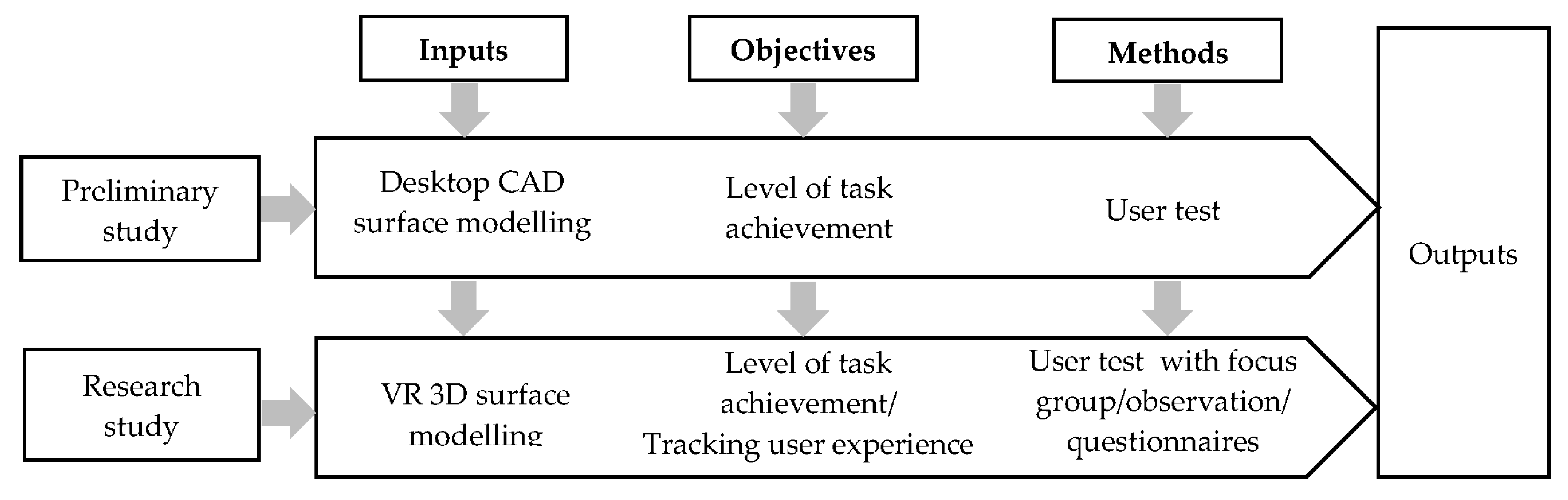
2. Methodology
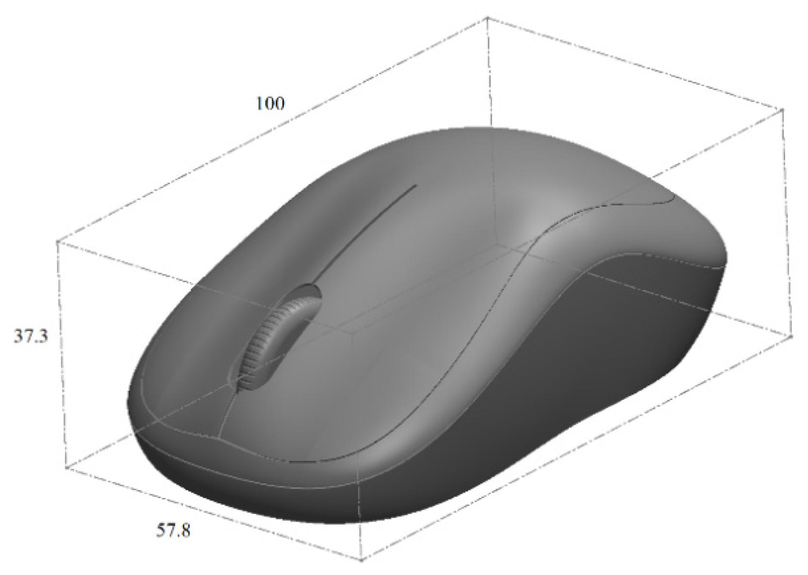
2.1. Preliminary Study
2.2. Research Study: VR 3D Modelling Study
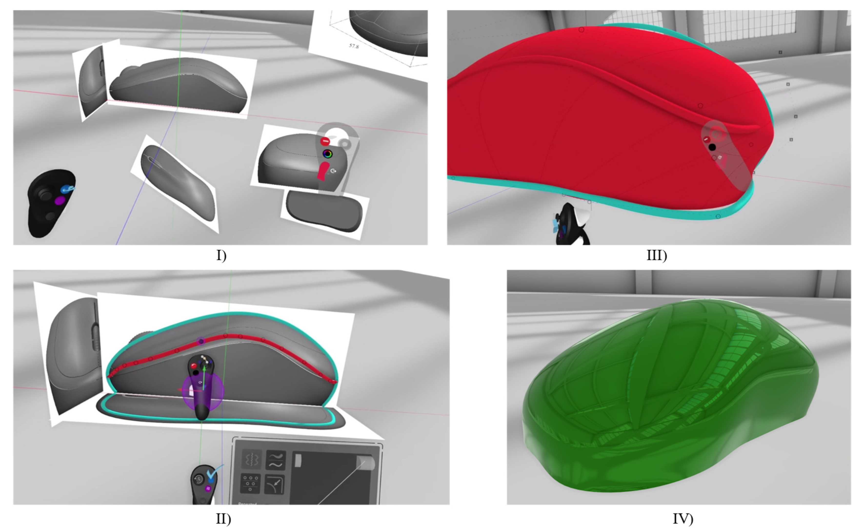
2.2.1. VR 3D Freeform Modelling Steps
2.2.2. Participants
2.2.3. Study Preparation
2.2.4. Focus Group Study
3. Results
3.1. Preliminary Study: Desktop Modelling
Findings
3.2. Research Study: VR 3D Modelling Results
3.2.1. Observations
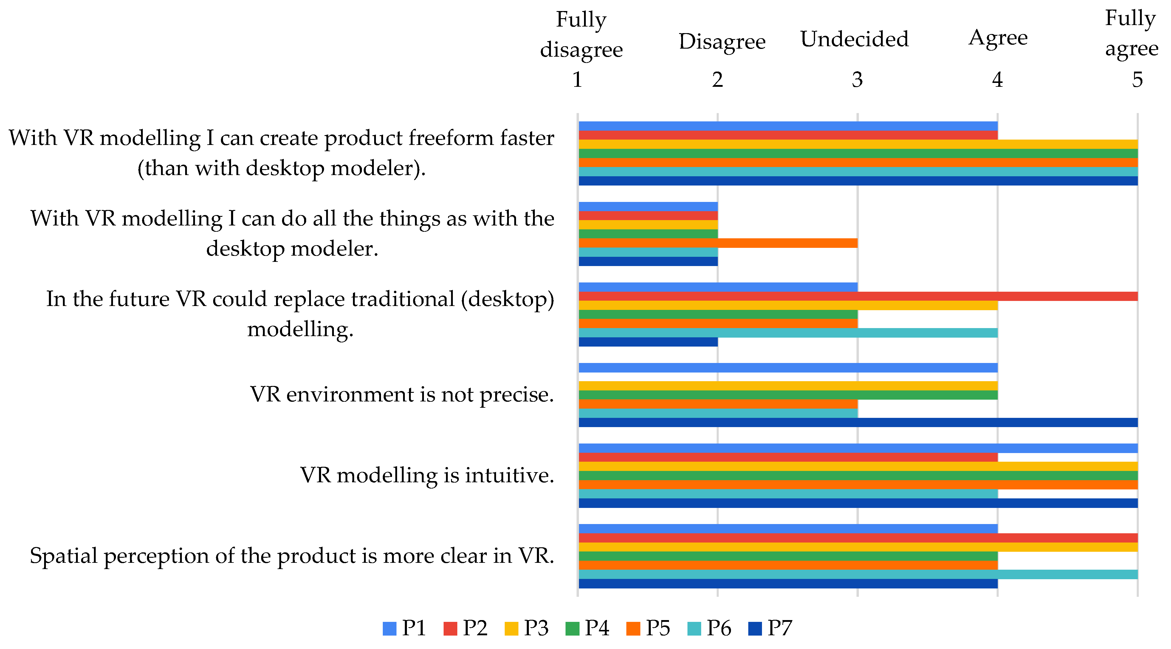
3.2.2. Questionnaire after Modelling
4. Discussion
5. Conclusions
Author Contributions
Funding
Informed Consent Statement
Conflicts of Interest
References
- Van Goethem, S.; Watts, R.; Dethoor, A.; Van Boxem, R.; van Zegveld, K.; Verlinden, J.; Verwulgen, S. The Use of Immersive Technologies for Concept Design. Adv. Intell. Syst. Comput. 2020, 1217, 698–704. [Google Scholar] [CrossRef]
- Ye, J.; Campbell, R.I.; Page, T.; Badni, K.S. An Investigation into the Implementation of Virtual Reality Technologies in Support of Conceptual Design. Des. Stud. 2006, 27, 77–97. [Google Scholar] [CrossRef]
- Balzerkiewitz, H.-P.; Stechert, C. The Evolution of Virtual Reality Towards the Usage in Early Design Phases. Proc. Des. Soc. Des. Conf. 2020, 1, 91–100. [Google Scholar] [CrossRef]
- Muñoz-Saavedra, L.; Miró-Amarante, L.; Domínguez-Morales, M. Augmented and Virtual Reality Evolution and Future Tendency. Appl. Sci. 2020, 10, 322. [Google Scholar] [CrossRef] [Green Version]
- Milgram, P.; Takemura, H.; Utsumi, A.; Kishino, F. Augmented Reality: A Class of Displays on the Reality-Virtuality Continuum. Telemanipulator Telepresence Technol. 1995, 2351, 282–292. [Google Scholar] [CrossRef]
- Urbas, U.; Ariansyah, D.; Erkoyuncu, J.A.; Vukašinović, N. Augmented Reality Aided Inspection of Gears. Teh. Vjesn. 2021, 28, 1032–1037. [Google Scholar] [CrossRef]
- Urbas, U.; Vrabič, R.; Vukašinović, N. Displaying Product Manufacturing Information in Augmented Reality for Inspection. Procedia CIRP 2019, 81, 832–837. [Google Scholar] [CrossRef]
- Masclet, C.; Poulin, M.; Boujut, J.-F.; Becattini, N. Real-Time Coding Method and Tool for Artefact-Centric Interaction Analysis in Co-Design Situations Assisted by Augmented Reality. Int. J. Interact. Des. Manuf. 2020, 14, 1141–1157. [Google Scholar] [CrossRef]
- Eschen, H.; Kötter, T.; Rodeck, R.; Harnisch, M.; Schüppstuhl, T. Augmented and Virtual Reality for Inspection and Maintenance Processes in the Aviation Industry. Procedia Manuf. 2018, 19, 156–163. [Google Scholar] [CrossRef]
- Davila Delgado, J.M.; Oyedele, L.; Demian, P.; Beach, T. A Research Agenda for Augmented and Virtual Reality in Architecture, Engineering and Construction. Adv. Eng. Inform. 2020, 45, 101122. [Google Scholar] [CrossRef]
- Berg, L.P.; Vance, J.M. Industry Use of Virtual Reality in Product Design and Manufacturing: A Survey. Virtual Real. 2017, 21, 1–17. [Google Scholar] [CrossRef]
- Gebhardt, S.; Pick, S.; Voet, H.; Utsch, J.; Al Khawli, T.; Eppelt, U.; Reinhard, R.; Buscher, C.; Hentschel, B.; Kuhlen, T.W. FlapAssist: How the Integration of VR and Visualization Tools Fosters the Factory Planning Process. In Proceedings of the 2015 IEEE Virtual Reality Conference, Arles, France, 23–27 March 2015; pp. 181–182. [Google Scholar] [CrossRef]
- Zhaparov, M.K.; Nassen, Y. 3D Modelling Based on Virtual Reality. In Proceedings of the 2016 6th International Conference-Cloud System and Big Data Engineering (Confluence), Noida, India, 14–15 January 2016; pp. 399–402. [Google Scholar] [CrossRef]
- Peng, Q. Virtual Reality Technology in Product Design and Manufacturing. In Proceedings of the Proceedings of the Canadian Engineering Education Association (CEEA), Winnipeg, MB, Canada, 22–24 July 2007; pp. 358–363. [Google Scholar]
- Horvat, N.; Škec, S.; Martinec, T.; Lukačević, F.; Perišić, M.M. Comparing Virtual Reality and Desktop Interface for Reviewing 3D CAD Models. Proc. Des. Soc. Int. Conf. Eng. Des. 2019, 1, 1923–1932. [Google Scholar] [CrossRef] [Green Version]
- Berg, L.P.; Vance, J.M. An Industry Case Study: Investigating Early Design Decision Making in Virtual Reality. J. Comput. Inf. Sci. Eng. 2017, 17, 011001. [Google Scholar] [CrossRef]
- Fain, N.; Kline, M.; Vukasinovic, N.; Duhovnik, J. The Impact of Management on Creativity and Knowledge Transfer in an Academic Virtual Enterprise. Tech. Gaz. 2010, 17, 347–351. [Google Scholar]
- Vukašinović, N.; Pavković, N. Use of Virtual Mobility to Facilitate Modern Project-Based NPD Education. Int. J. Eng. Educ. 2017, 33, 2008–2019. [Google Scholar]
- Safadel, P.; White, D. Effectiveness of Computer-Generated Virtual Reality (VR) in Learning and Teaching Environments with Spatial Frameworks. Appl. Sci. 2020, 10, 5438. [Google Scholar] [CrossRef]
- Wolfartsberger, J. Analyzing the Potential of Virtual Reality for Engineering Design Review. Autom. Constr. 2019, 104, 27–37. [Google Scholar] [CrossRef]
- Burghardt, A.; Szybicki, D.; Gierlak, P.; Kurc, K.; Pietruś, P.; Cygan, R. Programming of Industrial Robots Using Virtual Reality and Digital Twins. Appl. Sci. 2020, 10, 486. [Google Scholar] [CrossRef] [Green Version]
- Wonsick, M.; Padir, T. A Systematic Review of Virtual Reality Interfaces for Controlling and Interacting with Robots. Appl. Sci. 2020, 10, 9051. [Google Scholar] [CrossRef]
- Coburn, J.Q.; Salmon, J.L.; Freeman, I. Effectiveness of an Immersive Virtual Environment for Collaboration With Gesture Support Using Low-Cost Hardware. J. Mech. Des. 2018, 140, 042001. [Google Scholar] [CrossRef] [Green Version]
- Gong, L.; Söderlund, H.; Bogojevic, L.; Chen, X.; Berce, A.; Fast-Berglund, Å.; Johansson, B. Interaction Design for Multi-User Virtual Reality Systems: An Automotive Case Study. Procedia CIRP 2020, 93, 1259–1264. [Google Scholar] [CrossRef]
- Tang, Y.M.; Au, K.M.; Lau, H.C.W.; Ho, G.T.S.; Wu, C.H. Evaluating the Effectiveness of Learning Design with Mixed Reality (MR) in Higher Education. Virtual Real. 2020, 24, 797–807. [Google Scholar] [CrossRef]
- Radianti, J.; Majchrzak, T.A.; Fromm, J.; Wohlgenannt, I. A Systematic Review of Immersive Virtual Reality Applications for Higher Education: Design Elements, Lessons Learned, and Research Agenda. Comput. Educ. 2020, 147, 103778. [Google Scholar] [CrossRef]
- Kuppuswamy, R.; Mhakure, D. Project-Based Learning in an Engineering-Design Course—Developing Mechanical- Engineering Graduates for the World of Work. Procedia CIRP 2020, 91, 565–570. [Google Scholar] [CrossRef]
- Ulrich, K.T.; Eppinger, S.D.; Yang, M.C. Product Design and Development, 7th ed.; McGraw-Hill: New York, NY, USA, 2019; ISBN 978-1260043655. [Google Scholar]
- Häggman, A.; Tsai, G.; Elsen, C.; Honda, T.; Yang, M.C. Connections Between the Design Tool, Design Attributes, and User Preferences in Early Stage Design. J. Mech. Des. 2015, 137, 071408. [Google Scholar] [CrossRef] [Green Version]
- Wang, G.G. Definition and Review of Virtual Prototyping. J. Comput. Inf. Sci. Eng. 2002, 2, 232–236. [Google Scholar] [CrossRef] [Green Version]
- Berni, A.; Borgianni, Y. Applications of Virtual Reality in Engineering and Product Design: Why, What, How, When and Where. Electronics 2020, 9, 1064. [Google Scholar] [CrossRef]
- Joundi, J.; Christiaens, Y.; Saldien, J.; Conradie, P.; De Marez, L. An Explorative Study Towards Using VR Sketching As a Tool for Ideation and Prototyping in Product Design. Proc. Des. Soc. Des. Conf. 2020, 1, 225–234. [Google Scholar] [CrossRef]
- Oti, A.; Crilly, N. Immersive 3D Sketching Tools: Implications for Visual Thinking and Communication. Comput. Graph. 2021, 94, 111–123. [Google Scholar] [CrossRef]
- Sifakis, E. FEM Simulation of 3D Deformable Solids: A Practitioner’s Guide to Theory, Discretization and Model Reduction. In Proceedings of the ACM SIGGRAPH 2012 Courses, SIGGRAPH’12, Los Angeles, CA, USA, 5–9 August 2012; Association for Computing Machinery: New York, NY, USA, 2012; pp. 1–50. [Google Scholar]
- Misztal, S.; Ginkel, I. Abstract Surface Modeling for Concurrent Form Finding and Class a Surfacing in Computer-Aided Design. In Proceedings of the 24th International Conference in Central Europe on Computer Graphics, Visualization and Computer Vision, Plzen, Czech Republic, 30 May–3 June 2016; pp. 41–47. [Google Scholar]
- Zhong, Y.; Ma, W.; Shirinzadeh, B. A Methodology for Solid Modelling in a Virtual Reality Environment. Robot. Comput. Integr. Manuf. 2005, 21, 528–549. [Google Scholar] [CrossRef]
- Vukašinović, N.; Duhovnik, J. Creating Complex CAD Models with Freeform Surfaces. In Advanced CAD Modeling; Springer Nature Switzerland AG: Cham, Switzerland, 2019; pp. 81–109. [Google Scholar]
- Vukašinović, N.; Duhovnik, J. Introduction to freeform surface modelling. In Advanced CAD Modeling; Springer Nature Switzerland AG: Cham, Switzerland, 2019; pp. 1–48. [Google Scholar]
- Mathias, M.; Velay, X.; Wade, R. The Challenges of Assessing Digital Product Design. In Proceedings of the DS 46: E&PDE 2008, the 10th International Conference on Engineering and Product Design Education, Barcelona, Spain, 4–5 September 2008; pp. 309–314. [Google Scholar]
- Setzer, J. Using Curvature Combs to Inspect Curvature. Available online: https://blogs.solidworks.com/solidworksblog/2012/07/using-curvature-combs-to-inspect-curvature.html (accessed on 16 July 2021).
- Baxter, K.; Courage, C.; Caine, K. Focus Groups. In Understanding Your Users: A Practical Guide to User Research Methods; Morgan Kaufmann: Burlington, MA, USA, 2015; pp. 338–376. ISBN 978-0-12-800232-2. [Google Scholar]
- Krueger, R.A.; Casey, M.A. Focus Groups: A Practical Guide for Applied Research, 5th ed.; SAGE Publications: Thousand Oaks, CA, USA, 2014; ISBN 9781483365244. [Google Scholar]


| Key Steps | Imported Images | Sketches | Surfaces | Geometry Matching | Surface Transitions | Solid Body | Details |
|---|---|---|---|---|---|---|---|
| Criteria | Importing, scaling, and placing of images. Four images are needed. | Sketches for surfaces. | Surface shape, gaps, errors. | Surfaces match the required shape. | Tangency over the mirror plane. | Solid body creation. | Split surface and mouse wheel. |
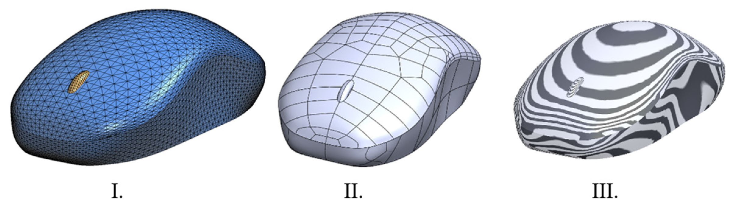
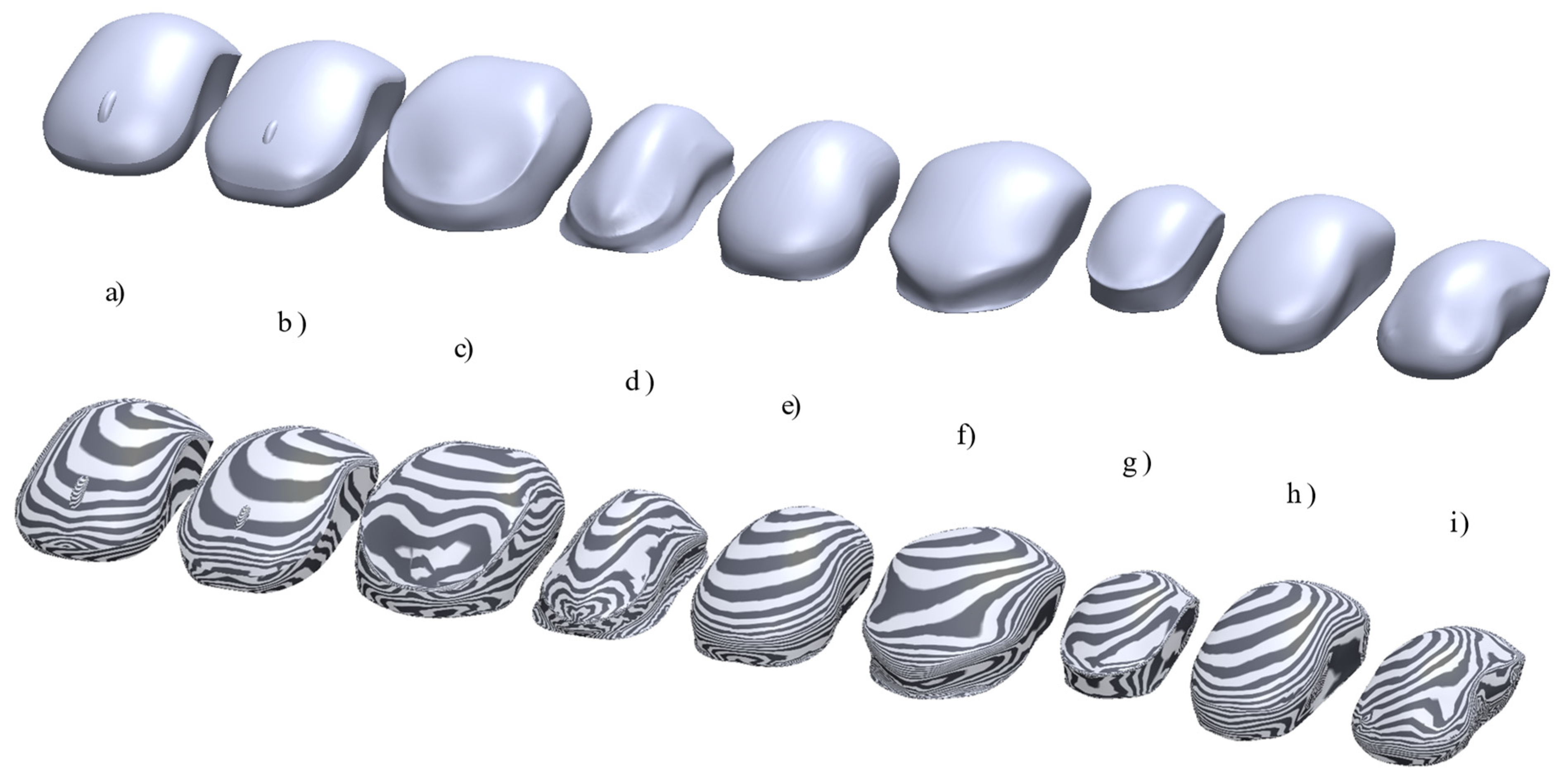
| Quality indicators | Visual indication | Visual indication | Mesh preview. Curvature combs. | Visual indication. Volume and mass data. | Zebra * stripes. Curvature * combs. | Software readout. | Visual indication. |
| Level of Achievement [%] | Imported Images | Sketches/Projected Sketches | Surfaces | Geometry Matching | Surface Transitions | Solid Body | Details |
|---|---|---|---|---|---|---|---|
| achieved | 93 | 57 | 36 | 36 | 29 | 43 | 21 |
| not achieved | 7 | 14 | 14 | 50 | 57 | 57 | 43 |
| partly achieved | 0 | 29 | 50 | 14 | 14 | 0 | 36 |
| Average time [min]: | 15 | 19 | 25 | / | / | 4 | 20 |
| Case | (a) | (b) | (c) | (d) | (e) | (f) | (g) | (h) | (i) |
|---|---|---|---|---|---|---|---|---|---|
| Volume [cm3] | 130.5 | 144.0 | 183.7 | 80.9 | 119.3 | 165.0 | 64.4 | 118.3 | 93.4 |
| Level of Achievement [%] | Imported Images | Sketches/Projected Sketches | Surfaces | Geometry Matching | Surface Transitions | Solid Body |
|---|---|---|---|---|---|---|
| achieved | 86 | 57 | 86 | 29 | 71 | 100 |
| not achieved | 0 | 0 | 0 | 29 | 0 | 0 |
| partly achieved | 14 | 43 | 14 | 42 | 29 | 0 |
| Average time [min]: | 5:30 | 12:17 | 17:07 | / | / | / |
| VR Modelling Phases | Researchers’ Observations |
|---|---|
| Imported images | Importing alone was easy and none of the participants complained about it. They all said it was intuitive. |
| Sketches/projected sketches | Placing the sketches in the coordinate system was reasonably quick, but scaling the images caused problems for the participants. |
| Surfaces | Creating the surface patch was quick but fitting the surface to the curves was time consuming and required some extra work. |
| Geometry matching | The VR process does not allow for exact positioning on planar views (e.g., top view, side view), therefore, the alignment of the geometry must be done from a 3D perspective, which caused issues with geometry fitting to the reference images. |
| Surface transition | At this point, participants have prepared half of the surface model for mirroring on the right plane. They had difficulties creating a suitable surface model with an appropriate amount of vertices to achieve symmetry and frequently needed help with the controls. |
| Solid body | All participants succeeded in creating a fully enclosed surface model, which enabled the conversion of the model into a solid body. This step requires some additional work for model conversion in desktop tools. However, some participants did not succeed in creating the model with the right geometry and proportions. |
| 1. For freeform modelling I would rather use VR than traditional modelling. | ||
| P1 | I don’t know | Certain things are easier in VR, even though I have more experience with classical (desktop) modelling. With more experience it would be easier to precisely model the surfaces. |
| P2 | I don’t know | It is useful, but it very much depends on the purpose. VR does not have the functionalities for numerical simulations etc. and for more detailed analyses I would rather decide for traditional modelling(desktop). For designing it is nicer to work in a VR modeller. |
| P3 | Yes | Faster and simpler. |
| P4 | I don’t know | It might be faster to use for visualizing some rough ideas, which could later be edited and finalized in a traditional modeller (desktop). |
| P5 | Yes | Faster and more fun. |
| P6 | Yes | Easier editing of the freeform shapes. |
| P7 | I don’t know | Depends on the application: For reverse engineering of the object, I would rather use classical tools because it seems to me that they enable for more control. For designing from scratch, I would rather use VR because it enables more freedom, better perception of the details, it is more intuitive... |
| 2. Is freeform modelling easier for you in the VR environment than in a desktop modeller? | ||
| P1 | I don’t know | The same answer as before, current experience in desktop modeller. |
| P2 | Yes | Because the vertices are more simply positioned and enable easier control of the movement in the 3D space. |
| P3 | Yes | VR modeler(interface) enables interaction with the model directly in three dimensions. |
| P4 | Yes | Creating and forming the surface is faster, it is easier to move around the model-turning of the model and moving the control points. |
| P5 | Yes | VR is more intuitive. |
| P6 | Yes | Because it is easier to edit the freeform surfaces. |
| P7 | Yes | There are fewer problems/errors that there would be in the desktop modeller, everything somehow ‘works out by itself. |
Publisher’s Note: MDPI stays neutral with regard to jurisdictional claims in published maps and institutional affiliations. |
© 2021 by the authors. Licensee MDPI, Basel, Switzerland. This article is an open access article distributed under the terms and conditions of the Creative Commons Attribution (CC BY) license (https://creativecommons.org/licenses/by/4.0/).
Share and Cite
Vlah, D.; Čok, V.; Urbas, U. VR as a 3D Modelling Tool in Engineering Design Applications. Appl. Sci. 2021, 11, 7570. https://doi.org/10.3390/app11167570
Vlah D, Čok V, Urbas U. VR as a 3D Modelling Tool in Engineering Design Applications. Applied Sciences. 2021; 11(16):7570. https://doi.org/10.3390/app11167570
Chicago/Turabian StyleVlah, Daria, Vanja Čok, and Uroš Urbas. 2021. "VR as a 3D Modelling Tool in Engineering Design Applications" Applied Sciences 11, no. 16: 7570. https://doi.org/10.3390/app11167570
APA StyleVlah, D., Čok, V., & Urbas, U. (2021). VR as a 3D Modelling Tool in Engineering Design Applications. Applied Sciences, 11(16), 7570. https://doi.org/10.3390/app11167570