Article

Development of Hydraulic Turbodrills for Deep Well Drilling

by
Mikhail V. Dvoynikov
,
Dmitry I. Sidorkin
*,
Andrey A. Kunshin
and
Danil A. Kovalev
Arctic Competence Center, Saint Petersburg Mining University, 199106 Saint Petersburg, Russia
*
Author to whom correspondence should be addressed.
Appl. Sci. 2021, 11(16), 7517; https://doi.org/10.3390/app11167517
Submission received: 20 July 2021 / Revised: 8 August 2021 / Accepted: 11 August 2021 / Published: 16 August 2021
(This article belongs to the Topic Industrial Engineering and Management)

Abstract

:
The article discusses the possibility of improving the design of the turbine of a hydraulic drilling machine for drilling wells in very hard rocks and at considerable depths (5000–12,000 m). The analysis of the results of studies on the technical and technological characteristics of downhole drilling motors showed that it is impossible to ensure stable operation due to the limitation on the operating temperature, while with an increase in the flow rate of the drilling fluid, they do not provide the required power on the spindle shaft, and cannot reach high-speed drilling. In such conditions, turbodrills with a significant change in the profile of the stator and rotor blades and a reinforced support unit are most suitable. The paper presents an invariant mathematical model, which made it possible to determine the optimal geometric parameters based on preselected boundary conditions and the main performance characteristics of the turbine being developed. The results obtained were tested by the finite element method, which showed a convergence of 12.5%. At the same time, zones with the lowest and highest flow rates were identified. Additionally, this paper presents a comparative analysis of the obtained hydraulic turbine with turbodrills of the TSSH-178T and Neyrfor TTT 2 7/8 brands. In comparison with the domestic turbodrill, the developed turbine design shows a 13-fold reduction in its length and a 3-fold reduction in torque, provided that the maximum power is increased by 1.5 times. In comparison with the foreign analog, there is a decrease in length by 8.5 times, an increase in torque by 5 times, and in maximum power by 6.5 times.

1. Introduction

All over the world, countries are interested in drilling deep and ultra-deep wells. Each country has its own interest; some need production wells and some need research wells [1,2]. However, they are united by the complexity of drilling such wells because the work is carried out in very hard rocks at high temperatures and using high-density drilling mud [3,4,5].
Currently, existing technologies do not allow for effective drilling in such conditions due to the fact that the loads on the drill string, bit, and hydraulic motor increase [6,7,8].
The most common downhole screw motors are unable to operate under these conditions due to the significant temperature limitation (up to 150 °C) [9,10,11]. In addition, their indisputable advantages in the field of creating significant torque elements at low speeds lead to the inappropriateness of their use in these conditions [12,13,14].
Based on the foregoing, the most effective technology for drilling such wells is the use of impregnated bits in combination with a high-speed hydraulic turbine engine [15,16].
The first turbine apparatus for drilling wells was developed in 1923 by M.A. Kapelyushnikov, together with S.M. Volokh. and Kornev N.A., called the Kapelyushnikov turbodrill (12 HP, single-stage turbine, multi-stage planetary gearbox). The final design of the turbodrill, which has become widespread, was created by PP Shumilov, RA Ioannesyan, EI Tagiyev, and MT Gusman [17,18].
At the moment, there are high-speed turbodrills in Russia, the rotational speed of which does not exceed 1300 rpm (revolutions per minute), for example, turbodrills developed by VNIIBT-Drilling Instrument. These include models of turbodrills T-4 3/4, T-6 3/4, and TSSh-178T [19,20].
Abroad, there are turbodrills whose rotational speed reaches 2500 rpm, for example, Neyrfor TTT 2 1/8 [21] and Neyrfor TTT 2 7/8 [22], developed by Schlumberger [23,24]. However, these turbodrills have a significant limitation associated with their diameter, hence the small working area of the blades, due to which the hydraulic energy of the drilling fluid flow is converted into the rotation of the turbodrill shaft [25,26].
From the above technical limitation, it follows that it is necessary to develop a turbodrill with a rotation speed equal to 2500 rpm, and with the possibility of increased mechanical drilling speed in hard and abrasive formations, reducing the drilling time and reducing economic costs, while maintaining high reliability [27,28].

2. Development of Mathematical Model

The key component of the turbodrill, which creates the necessary performance characteristics, is the hydraulic turbine [29,30,31].
It is required to create an invariant model that allows for the identification of the optimal operating ranges, as well as to develop the geometric parameters of the turbine (namely, the rotor and stator), enabling the required power to be generated at increased spindle shaft speeds [32,33].
For this purpose, a parameter was determined that affects the increase in the energy efficiency of the device in relation to the introduced technical changes to the turbine [34]. To do this, the formula for the turbodrill turbine torque was used, as follows:
M = ρ · Q · D 2 · c 1 u c 2 u ,
where
  • c 1 u = c z · c t g α —equivalent speed in the rotor, m/s,
  • c 2 u = u c z · c t g β —equivalent speed in the stator, m/s,
  • c z = Q π · D · l —axis velocity of the liquid, m/s,
  • u = π · D · n —district fluid velocity, m/s,
  • M —torque, Nm,
  • ρ —density, kg/m3,
  • Q —drilling fluid flow rate, m3/s,
  • D —medium turbine diameter, m,
  • α —stator blade angle of inclination, n’,
  • β —rotor blade angle of inclination, n’,
  • n —rotation frequency, rev/s,
  • l —radial length of turbodrill blades, m.
Let us represent Formula (1) in the following form:
M = ρ · Q · D 2 · Q · c t g α π · D · l π · D · n + Q · c t g β π · D · l ,
It is obvious that the generated torque is most influenced by the flow rate and the tilt angles of the stator and rotor blades. Moreover, it is possible to divide the influencing parameters into the technological, which includes the flow rate, and the constructive—the angles of inclination of the stator and rotor blades [35,36].
Depending on the ratio of the angles of inclination of the stator and rotor blades, the engine can either be low-torque high-speed (low-circulation type) or high-torque low-speed (high-circulation type) [17]. In our case, we chose the normal type of turbine in view of its maximum energy efficiency.
The main factor by which we can achieve the set indicators is the geometry of the blades of the rotor–stator working pair, in view of obtaining the maximum indicators of torque and power [37,38]. This is why we focused on changing the geometry in further calculations.

3. Simulation of the Investigated Object

3.1. Study of the Mathematical Model

To find the optimal output angles of the stator and rotor blades of the turbodrill from the point of view of the power of the working pair, which will make it possible to obtain the working pair with the maximum power and limited rotation frequency, we used the following equation, which determines the relationship between the angles and the resulting power [39,40,41]:
P , β = M , β · ω ,
ω = 2 · π · n 60 ,
Substituting Formulas (2) and (4) into Formula (3), we get the following:
P , β = ρ · Q · D · ω 2 · π · Q · c t g α π · D · l D · ω 2 · π + Q · c t g β π · D · l ,
where
  • P —power, W,
  • ω —rotation frequency, rad/s,
  • n —rotation frequency, rpm.
Since we were striving to solve the optimization problem in the range of angles of inclination of the blades, we carried out differentiation in order to investigate the convexity of the above function in the considered range.
2 P α 2 = C 1 · c t g α s i n 2 α ,
2 P β 2 = C 2 · c t g β s i n 2 β ,
where C 1 , 2 —positive permanent.
Since the mixed derivatives are identically zero, and the second derivatives with respect to each of the variables are non-negative in the range under consideration, there is a global optimum. Let us introduce a constraint function to avoid considering physically unrealizable configurations:
ω α , β = 60 · Q   l · π 2 · D 2 · c t g α + c t g β ,
With the limitation of −∞ < n ≤ 5000 rpm, the maximum rotational speed is comparable with the maximum rotational speed of the Neyrfor turbodrill [21].
The confidence region optimization algorithm was used on the basis that it is well suited for handling nonlinear boundaries similar to those in the present problem [42]. Subsequent consideration gives a number of pairs of angles of equal power values, from which any one can be freely selected.
The trust region optimization method is named so based on the determination of the region around the current iteration, where the quadratic model approximates the objective function (the so-called trust region) rather well, based on the given parameter. The algorithm step at each iteration is calculated by solving the next subproblem of quadratic optimization.
The algorithm for solving the subproblem is chosen separately and is usually based on gradients. The Steihaug conjugate gradient algorithm, convenient for approximation, is often used, which guarantees the convergence of quadratic functions in a finite number of iterations that do not exceed the number of dimensions of the real numerical space formed by the variables under consideration, while not requiring an expensive estimate of the Hessian for the problem under consideration [43].
For the search, we used the optimization by the trust region method, formulating the optimization problem as the following:
min R q f q i y i 2 ,  
where
  • q —generalized variables of the desired values,
  • y —valid speed values of rotation,
  • f q —rotation frequency function values for a set of generalized variables,
  • R q —real space with the length of the q vector.
The algorithm uses a barrier method, by which subproblems are solved using sequential programming of the trust region. Each barrier subproblem has the following form:
G i v e n   t h a t   h x = 0 ,   g x + s = 0 ,
min x , s f x μ i = 1 m ln s i ,
where
  • h, g—restriction function,
  • μ —positive barrier parameter, variable s is to be positive.
If we ensure the convergence of µ to zero, the sequence of solutions to the introduced problem should usually converge to a stationary point of the original nonlinear problem. As in some interior-point methods for linear programming, the applied algorithm does not require satisfiability of iterations with respect to inequality constraints in the original problem, but only forces some variables to remain positive. To characterize the solution to the barrier problem, we introduce its Lagrangian form:
L x , s , λ h , λ g = f x μ i = 1 m ln s i + λ h T h x + λ g T g x + s ,
where λ h , λ g —Lagrange multipliers.
We represent an approximate solution to the barrier problem in the following form:
x ^ , s ^ : E x ^ , s ^ , μ = m a x | f x + A h x λ h + A g x λ g | , | S λ g μ e | , | h x | , | g x + s | ϵ μ ,
where
  • e—single vector-pillar,
  • S—diagonal matrix,
  • A h , g x —vector line components of the gradient corresponding to the restriction function.
The resulting system corresponds to the disordered Kuhn–Tucker system [44]. The accuracy parameter ϵ μ decreases, ideally converging to zero, iteratively from one barrier problem to another.
To obtain a rapidly converging algorithm, it is necessary to carefully control the rate of decrease in the barrier parameter µ and the accuracy parameter ϵ μ . This question was studied in the context of the applied algorithm in [45]. Most of the work of the algorithm clearly lies in Step 1, in the approximate solution of a problem with constraints in equality with an implicit lower bound on the translation variables. To do this efficiently, we used an adaptation of iterative quadratic programming with equality constraints with confidence regions proposed by Bird and described in [46]. We followed the sequential quadratic programming approach because it is efficient for solving problems with equality constraints even when the problem is ill-conditioned and the constraints are highly nonlinear [47]. Moreover, using trust-region strategies to globalize sequential solutions makes it easier to apply the Hessian to non-convex problems. The applied algorithm, proposed by Beard, is to formulate a quadratic model in a sequential programming iteration and to define a (scaled) confidence region. They are designed to create steps that have some of the properties of primary dual iterations and avoid getting too close to the edge of the feasible region. Each iteration of such a method begins with the construction of a quadratic model of the Lagrange function. Step d of the algorithm is calculated by minimizing the quadratic model, provided that the linear approximation of the constraints is satisfied and provided that the confidence region is limited at this step. If Step d gives a sufficient decrease in the selected quality function, it is accepted; otherwise, the step is rejected, the zone of confidence is reduced, and a new step is calculated.

3.2. Results of Mathematical Modeling

Liquid flow conditions: flow rate of 50 l/s and pressure drop in the turbine of 438,649.08 Pa. Overall dimensions of the turbine: outer diameter of 195 mm, average diameter of 160 mm, radial blade length of 22 mm, section height of 18 mm, and gap between sections of 8 mm.
From the solution described above, we obtained the angle of inclination of the rotor blade (12.18 n) and the angle of inclination of the stator blade (12.18 n) (the calculation is presented in the program). Substituting in the Formulas (2) and (5), the initial conditions of the fluid flow, and the required overall dimensions of the turbine, we performed the calculation, as follows:
M = 1000 · 0.05 · 0.16 2 ·
0.05 · c t g 12.18 π · 0.16 · 0.022 π · 0.16 · 2500 60 + 0.05 · c t g 12.18 π · 0.16 · 0.022 = 83.78   Nm
P = 1000 · 0.05 · π · 0.16 · 2500 60 ·
0.05 · c t g 12.18 π · 0.16 · 0.022 π · 0.16 · 2500 60 + 0.05 · c t g 12.18 π · 0.16 · 0.022 = 21932.45   W
The dependence of the technical characteristics on the rotational speed is presented in Figure 1 and in Table 1.
The maximum torque value is 167.6 Nm at a speed of 0 rpm, and it decreases to 0 Nm when the speed increases to 5000 rpm along a linear relationship ( y = 0.0335 x + 167.55 ). At a speed of 2500 rpm, the torque is 83.8 Nm.
The maximum power value is 21.9 kW at 2500 rpm, it decreases to 0 W when the speed increases to 5000 rpm according to the quadratic dependence ( y = 0.0035 x 2 + 17.546 x ).
The maximum value of the effective pressure drop is 438.6 kPa at a rotational speed of 2500 rpm and decreases to 0 Pa with an increase in the rotational speed to 5000 rpm according to the quadratic dependence ( y = 0.0702 x 2 + 350.92 x ).

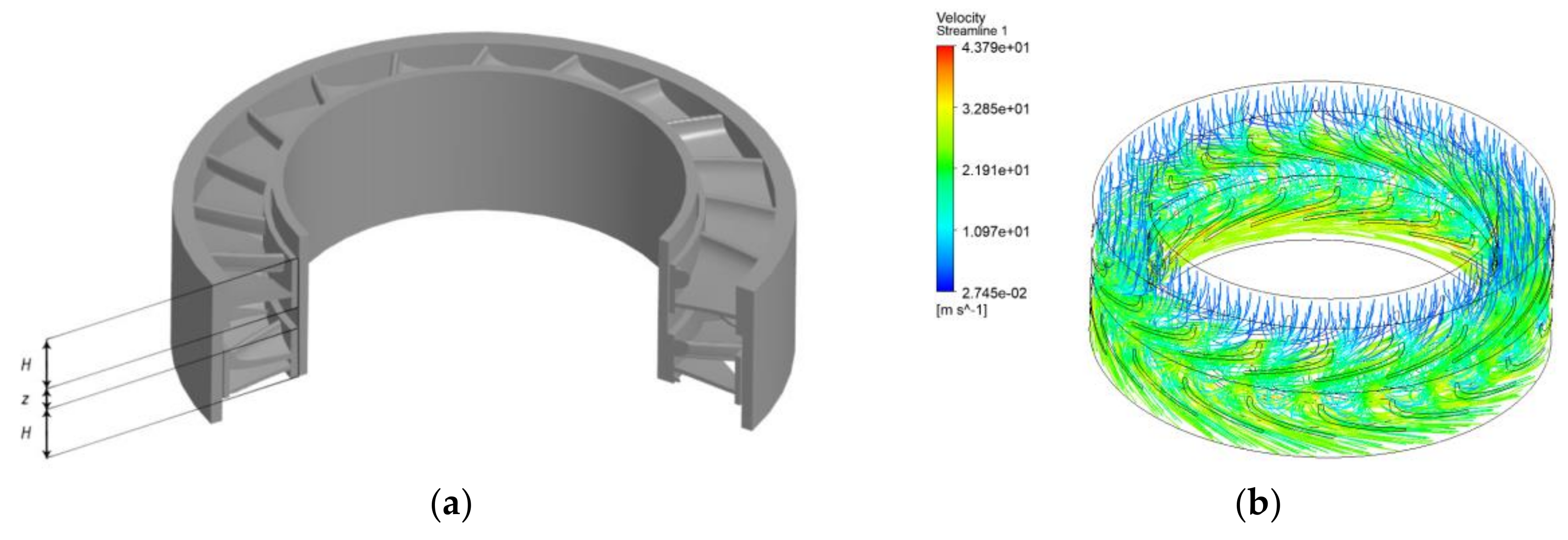
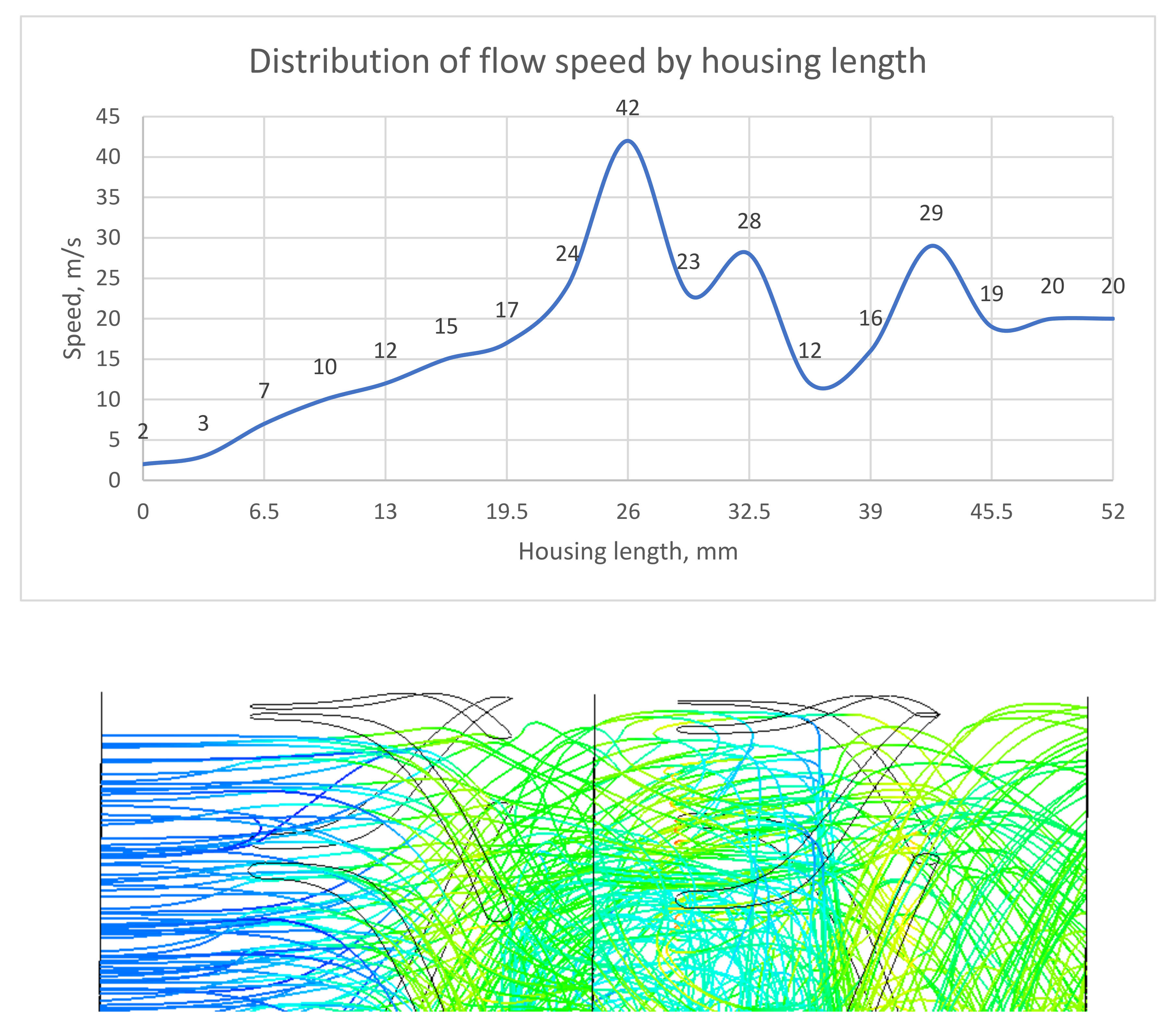
3.3. Testing the Research Results Using the Finite Element Method

Having simulated and built such a working pair (Figure 2, Table 2), as well as setting the boundary conditions for the calculation, we tested the developed turbine model by setting up a computational experiment in the Ansys Workbench program (Figure 3b) using direct numerical simulation of the process of functioning of the working pair of the turbine by the finite element method with a grid frequency of 5,034,474 elements and its type—tetrahedron [48].
Based on the results obtained, it can be concluded that the calculation model is adequate since the calculation in the program coincides with the calculation made according to the formulas. According to the formulas, the torque value is 83.78 Nm and the power is 21,932.45 W; in the program, they are 94.13 Nm and 24,630.45 W, respectively. Dividing the larger value by the smaller one, we obtained a ratio of 1.125, which indicates a calculation error of 12.5%.
Figure 3b displays the flow rate of fluid flows, which creates the rotation of the turbodrill. It can be concluded that the model was created correctly since it does not contain areas with a radical slowing down of the flow rate (Figure 4).
A gradual increase in the flow velocity in the range of 0 to 26 mm is associated with a decrease in the cross-section along the axis of fluid movement. By 26 mm, there is a sharp increase in the flow rate, resulting from the transition of fluid from the stator section to the rotating section of the rotor of the working pair. Further, the flow velocity fluctuates from 12 to 29 m/s in the range of 32.5–45.5 mm, associated with the occurrence of local resistances due to flow turbulization, which occurs due to a change in the direction of the fluid motion vector. In the interval of 45.5–52 mm, the flow velocity is equalized and is 20 m/s.

4. Comparative Analysis of the Developed Turbodrill

After we received the technical characteristics of the developed turbine pair, we carried out a comparative analysis based on the equality of the power of the turbodrills.
For comparison, let us take the TSSh-178T and Neyrfor 2 7/8 turbodrills (Table 3).
In comparison to the domestic turbodrill, the developed turbodrill shows a 13-fold reduction in length and a 3-fold reduction in torque, provided that the maximum power has increased by 1.5 times. When comparing the developed turbodrill to a foreign one, there is a decrease in length by 8.5 times, an increase in torque by 5 times, and an increase in maximum power by 6.5 times.
In addition, it is important to note that the outer diameter of the turbodrill, relative to the existing high-speed models, is larger (the developed turbine pair has 195 mm, and the Russian counterparts have 178 mm), and, accordingly, the working area of the blades is larger (by 100%).

5. Conclusions

An analysis of the existing designs of turbodrills was carried out in the work. The limitations of both domestic and foreign models of turbines for drilling in conditions of hard rocks, high temperature, and high density of the drilling mud were revealed. These include the following: domestic—low engine speed (up to 1300 rpm), and foreign—the maximum drilling diameter, suitable for drilling only sidetracks (body diameter up to 73 mm).
The problem is numerically solved using the method of optimization by the confidence region and dual minimization of the objective function. The results obtained were tested using direct numerical modeling of the process of action of the working pair of a turbodrill by the finite element method. The calculation results show that the highest power indicator of 21.9 kW at a rotational speed of 2500 rpm is achieved for a working pair with angles of inclination of the rotor blades and a stator of 12.18 degrees.
A comparative analysis of the developed turbodrill with TSSh-178T and Neyrfor 2 7/8 was carried out. It was found that the power is 292 kW (91 kW more (45%) than that of TSSH-178T, and 249 kW more (579%) than that of Neyrfor 2 7/8), the length is 0.52 m (6.58 m less (93%) and 4.05 m less (89%)) and the rotational speed is 2750 rpm (1467 rpm more (114%) and 250 rpm more (10%)).
It is planned to prototype a metal working pair model for physical modeling and obtaining practical technical characteristics.

Author Contributions

Conceptualization, M.V.D. and D.I.S.; methodology, A.A.K.; validation, M.V.D.; formal analysis, D.A.K.; investigation, A.A.K. and D.A.K.; resources, M.V.D.; data curation, D.A.K.; writing—original draft preparation, A.A.K. and D.A.K.; writing—review and editing, A.A.K.; visualization, D.A.K.; supervision, M.V.D.; project administration, D.I.S. All authors have read and agreed to the published version of the manuscript.

Funding

This research received no external funding.

Institutional Review Board Statement

Not applicable.

Informed Consent Statement

Not applicable.

Data Availability Statement

The data presented in this study are available on request from the corresponding author. The data are not publicly available due to the Federal Law of the Russian Federation “On Export Control”.

Conflicts of Interest

The authors declare no conflict of interest.

References

  1. How Deep can Superdeep Wells Be and What Were the USSR and the USA Looking for Inside the Earth? Available online: https://www.bbc.com/russian/vert-fut-48188978 (accessed on 5 July 2021).
  2. 10 Longest Wells in the World. Available online: https://www.kommersant.ru/doc/1580772 (accessed on 3 July 2021).
  3. Litvinenko, V.S.; Nikolaev, N.I. Process Fluids to Improve the Efficiency of Construction and Operation of Oil and Gas Wells; Notes of the Mining Institute; Saint-Petersburg Mining University: Saint-Petersburg, Russia, 2016; Volume 194, p. 84. [Google Scholar]
  4. Nikolaev, N.I. Development of Compositions of Drilling Fluids to Improve the Efficiency of Drilling Solid Rocks; Nikolaev, N.I., Leusheva, E.L., Eds.; Notes of the Mining Institute; Saint-Petersburg Mining University: Saint-Petersburg, Russia, 2016; Volume 219, pp. 412–420. [Google Scholar] [CrossRef]
  5. Nikolaev, N.I.; Ivanov, A.I. Improving the Efficiency of Drilling Oil and Gas Wells in Difficult Conditions; Notes of the Mining Institute; Saint-Petersburg Mining University: Saint-Petersburg, Russia, 2009; Volume 183, p. 308. [Google Scholar]
  6. Simonyants, S.L. Turbine Drilling Current Issues. Onshore and Offshore Oil and Gas Well Construction. 2006. Available online: http://ogbus.ru/files/ogbus/authors/Simonyanc/Simonyanc_1.pdf (accessed on 16 May 2021).
  7. Simonyants, S.L. Turbine Drilling Modernization Problem; Vector-Book: Tumen, Russia, 2003; 136p. [Google Scholar]
  8. Litvinenko, V.S.; Kudryashov, B.B. Modern Problems of Destruction of Rocks when Drilling Wells; Notes of the Mining Institute; Saint-Petersburg Mining University: Saint-Petersburg, Russia, 2017; Volume 148, p. 14. [Google Scholar]
  9. Oil and Gas Well Drilling Technology. Available online: https://portal.tpu.ru/SHARED/e/EPIKHIN/eng/Pedagogics/Tab/Lecture_TBNG_3.pdf (accessed on 23 June 2021).
  10. Leonov, E.G.; Simonyants, S.L. Improvement of the Technological Process of Well Deepening: Tutorial—M; RSU of Oil and Gas of the I.M. Gubkin: Moscow, Russia, 2014; 184p. [Google Scholar]
  11. Kamatov, K.A.; Kamatov, K.A. Solutions for drilling efficiency improvement in extreme geological conditions of Timano-Pechora region. In Proceedings of the SPE Russian Petroleum Technology Conference, Moscow, Russia, 15–17 October 2015. [Google Scholar] [CrossRef]
  12. Nikolaev, N.I. Theoretical and Experimental Studies of the Efficiency of Drilling Hard Rocks. In Oil and Gas and Mining; Nikolaev, N.I., Leusheva, E.L., Eds.; Bulletin PNRPU. Geology; Saint-Petersburg Mining University: Saint-Petersburg, Russia, 2015; pp. 38–47. [Google Scholar] [CrossRef]
  13. Simonyants, S.L.; Al Taee, M. Stimulation of the Drilling Process with the Top Driven Screw Downhole Motor. J. Min. Inst. 2019, 238, 438–442. [Google Scholar] [CrossRef] [Green Version]
  14. Dolgiy, I.E. Resistance of Rocks to Destruction When Drilling Wells; Dolgiy, I.E., Nikolaev, N.I., Eds.; Notes of the Mining Institute; Saint-Petersburg Mining University: Saint-Petersburg, Russia, 2016; Volume 221, pp. 655–660. [Google Scholar] [CrossRef]
  15. Zvarygin, B.I. Drilling Rigs and Well Drilling: Tutorial—Krasnoyarsk; Siberian Federal University: Krasnoyarsk, Russia, 2011; 256p. [Google Scholar]
  16. Superdeep Well Drilling. Available online: https://neftegaz.ru/science/booty/332315-sverkhglubokoe-burenie-skvazhin/ (accessed on 27 June 2021).
  17. Hlebnikov, D.; Mialitsin, N. VNIIBT-Drilling Tools. Methods for Improving the Turbodrill for Drilling in Hard Rocks. Drilling and Oil. 2013. Available online: https://burneft.ru/archive/issues/2013-06/13 (accessed on 27 April 2021).
  18. Bobrov, M.; Mialitsin, N.; Mingaraev, V.; Molodilo, V.; Pologeenko, V.; Asadchev, A.; Matveenko, D.; Judenko, L. Drilling by a High-Speed Turbodrill T-6 ¾ with Impregnated Bit at a Depth of 5780–6340 m. Available online: https://burneft.ru/archive/issues/2016-02/38 (accessed on 23 April 2021).
  19. Chudakov, G.F.; Korotaev, Y.A.; Solomatkin, A.A.; Mialitsin, N.Y. Turbine Turbodrill. Patent 2403366, 10 November 2009. [Google Scholar]
  20. Shumilov, V.P.; Martynov, V.N. Turbine Turbodrill. Patent 2269631, 19 August 2004. [Google Scholar]
  21. Neyrfor Thru-Tubing Turbodrill 2 1/8-in. Available online: https://www.slb.com/-/media/files/bdt/brochure/neyrfor-ttt-br-2.ashx (accessed on 23 April 2021).
  22. Neyrfor Thru-Tubing Turbodrill 2 7/8-in. Available online: https://www.slb.com/-/media/files/drilling/product-sheet/neyrfor-ttt-278-ps.ashx (accessed on 23 April 2021).
  23. High Temperature Drilling Operations. Available online: https://www.slb.com/-/media/files/drilling/brochure/ht-tools-br.ashx (accessed on 3 May 2021).
  24. Turbodrill Neyrfor and Impregnated Bits Kinetic Doubled ROP. Available online: https://www.slb.ru/library/projects/well_construction_cs/burovoe-oborudovanie-i-servisy/sistema-s-turboburom-neyrfor-i-impregnirovannymi-dolotami-kinetic-pozvolila-vdvoe-uvelichit-skorost-/ (accessed on 4 June 2021).
  25. Gorshkov, L.K.; Osetskiy, A.I. Development of Principles for the Design and Operation of New Diamond Rock Cutting Tools; Notes of the Mining Institute; Saint-Petersburg Mining University: Saint-Petersburg, Russia, 2012; Volume 197, p. 40. [Google Scholar]
  26. Mendebaev, T.N.; Smashov, N.Z.; Ismailov, H.K.; Izakov, B.K. Development of a resource-saving, small-sized downhole hydraulic machine for well drilling. East. Eur. J. Enterp. Technol. 2019, 6, 70–76. [Google Scholar] [CrossRef]
  27. Mialitsin, N.Y. New Solutions in the Design of Hudraulic Downhole Motors Manufactured by LLC «VNIIBT-Drilling Tools». Engineering Practice. 2012. Available online: https://oilgasconference.ru/upload/iblock/a84/20140210_122911_62376200.pdf (accessed on 18 March 2021).
  28. Buslaev, G.V. Development and field of the downhole multipurpose thrusting device for drilling of deep vertical and directional wells. Paper presented at the SPE Russian Petroleum Technology conference, Moscow, Russia, 26–28 October 2015. [Google Scholar] [CrossRef]
  29. Sazonov, Y.A.; Mokhov, M.A.; Demidova, A.A. Development of Small Hydraulic Downhole Motors for Well Drilling Applications. Am. J. Appl. Sci. 2016, 13, 1053–1059. [Google Scholar] [CrossRef] [Green Version]
  30. Biletsky, V.; Vitryk, V.; Mishchuk, Y.; Fyk, M.; Dzhus, A.; Kovalchuk, J. Examining the current of drilling mud in a power section of the screw downhole motor. East. Eur. J. Enterp. Technol. 2018, 2, 41–47. [Google Scholar] [CrossRef] [Green Version]
  31. Buslaev, G.V.; Ovchinnikov, V.A.; Rudnitsky, N.A. The optimization of a drill string bottom assembling of the well no 741 Kamyshinskaya. Sci. Tech. J. 2017. [Google Scholar] [CrossRef]
  32. Sazonov, Y.A.; Mokhov, M.A.; Frankov, M.A.; Ivanov, D.Y. The research of experimental downhole motor for well drilling using PDC type drill bits. Neftyznoe Khozyaystvo. Oil Ind. 2017, 10, 70–74. [Google Scholar] [CrossRef] [Green Version]
  33. Petrakov, D.G.; Kupavukh, K.S.; Kupavykh, A.S. The effect on fluid saturation on the elastic plastic properties of oil reservoir rocks. Curved Layer. Struct. 2020, 7, 29–34. [Google Scholar] [CrossRef]
  34. Simonyants, S.L. Application of Impregnated Diamond Bits with High Power Turbodrill; Drilling Contractors Association Bulletin: Moscow, Russia, 2011; pp. 7–9. [Google Scholar]
  35. Simonyants, S.L. Turbodrill and Screw Motor: Development Dialectics. In Proceedings of the SPE Russian Petroleum Technology Conference and Exhibition, Moscow, Russia, 24–26 October 2016. [Google Scholar] [CrossRef]
  36. Nutscova, M.V. Research of oil-based drilling fluid to improve the quality of wells completion. In Proceedings of the IOP Conference Series: Materials Science and Engineering, Bangkok, Thailand, 17–19 May 2019; Volume 666, p. 12065. [Google Scholar]
  37. Liu, T.; Leusheva, E.L.; Morenov, V.A.; Jiang, G.; Fang, C.; Zhang, L.; Zheng, S.; Yu, Y. Influence of polymer reagents in the drilling fluids on the efficience of deviated and horizontal wells drilling. Energies 2020, 13, 4704. [Google Scholar] [CrossRef]
  38. Baldenko, F.D. Drilling Equipment Calculations; RSU of Oil and Gas of the I.M. Gubkin: Moscow, Russia, 2012; pp. 384–409. [Google Scholar]
  39. Yu, W.; Bairu, X.; Zhiqiao, W.; Liguang, W.; Qin, Z. Design and Output Perfomance of Turbodrill Blade used in a Slim Borehole. Energies 2016, 9, 1035. [Google Scholar] [CrossRef] [Green Version]
  40. Ovchinnikova, E.N. Engineering ethics and training of mining engineers. In Proceedings of the Innovation-Based Development of The Mineral resources sector: Challenges and prospects—11th conference of the Russian-German raw materials, Potsdam, Germany, 7–8 November 2018. [Google Scholar]
  41. Lyagov, I.A.; Baldenko, F.D.; Lyagov, A.V.; Yamaliev, V.U.; Lyagova, A.A. Methodology for calculating technical efficiency of power sections in small-sized screw downhole motors for the «Perfobur» system. J. Min. Inst. 2019, 240, 694. [Google Scholar] [CrossRef]
  42. Simonyants, S.L. Turbine Design of a High-Power Turbodrill for Drilling with Diamond bits. Onshore and Offshore Oil and Gas Well Construction; (co-auth. Shumilov, V.P.; Litvyak, V.A.; Mnatsakanov, I.V.); RSU of Oil and Gas of the I.M. Gubkin: Moscow, Russia, 2011; pp. 19–23. Available online: http://www.vniioeng.ru/inform/construction/sod48/ (accessed on 28 April 2021).
  43. Byrd, R.H. Robust trust region methods for constrained optimization. In Proceedings of the Third SIAM Conference on Optimization, Houston, TX, USA, 17–20 May 1987. [Google Scholar] [CrossRef] [Green Version]
  44. John, H. Non-Linear and Dynamic Programming; Springer: Berlin/Heidelberg, Germany, 1964; 506p. [Google Scholar]
  45. Byrd, R.H.; Liu, G.; Nocedal, J. On the local behavior of an interior-point algorithm for nonlinear programming. In Numerical Analysis 1997; Griffiths, D.F., Higham, D.J., Eds.; Addison–Wesley Longman: Reading, MA, USA, 1997. [Google Scholar]
  46. Lalee, M.; Nocedal, J.; Plantenga, T. On the implementation of an algorithm for large-scale equality constrained optimization. SIAM J. Optim. 1998, 8, 682–706. [Google Scholar] [CrossRef] [Green Version]
  47. Fletcher, R. Practical Methods of Optimization, 2nd ed.; John Wiley: New York, NY, USA, 1990. [Google Scholar]
  48. Wang, Y.; Yao, J.; Li, Z. Design and Development of Turbodrill Blade Used in Crystallized Section; Hindawi Publishing Corporation: London, UK, 2014. [Google Scholar] [CrossRef]
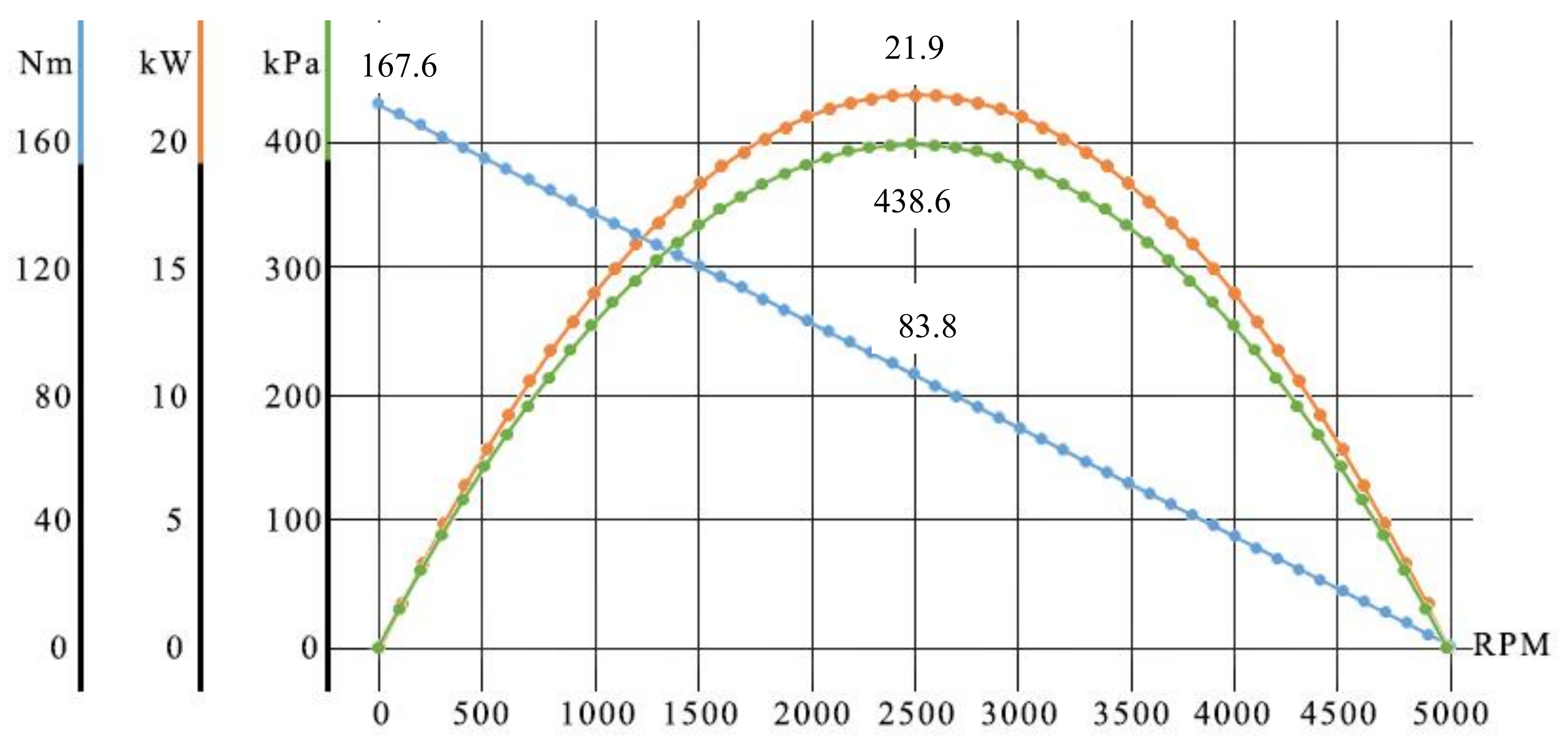
 [Green Version]
Figure 1. Chart of the specifications’ dependence on the speed.
Applsci 11 07517 g001
Figure 2. Model calculation in the «Setup» section: a—flow rate, b—pressure drop.
Applsci 11 07517 g002
Figure 3. Modeling a working turbine pair: (a)—Model of a turbodrill, where H—section height, and z—gap between sections; (b)—Display of the flow of fluid flows in the developed turbine pair.
Applsci 11 07517 g003
Figure 4. Distribution of the flow velocity along the length of the working pair.
Applsci 11 07517 g004
Table 1. Values of torque, power, and pressure drop from the speed of rotation.
Rotation Frequency, rpmTorque, NmPower, kWPressure Drop, kPa
0167.60.00.0
500150.87.9157.9
1000134.014.0280.7
1500117.318.4368.5
2000100.521.1421.1
250083.821.9438.6
300067.021.1421.1
350050.318.4368.5
400033.514.0280.7
450016.87.9157.9
50000.00.00.0
Table 2. Input data for model calculation in Ansys Workbench.
ParameterValue
Rotor blade angle, n’.12.18
Stator blade angle, n’.12.18
Flow rate, L/s50.00
Turbine pressure drop, kPa438.65
Table 3. Comparison of technical characteristics.
No.IndicatorModel of Turbodrill
TSSh-178TNeyrfor 2 7/8Developed Turbodrill
1Outer diameter of the case, mm17873195
2Turbodrill length, mm71004572520
3Drilling fluid flow rate, l/s28–386.3–7.545–55
4Drilling mud density, g/cm31.0Before 2.161.0
5Torque, Nm1630–3000Before 203679–1013
6Operating speed, rpm945–12832000–25002250–2750
7Turbine pressure drop, MPa5.4–9.27.6–11.43.6–5.3
8Maximum power, kW80–20124–43160–292
Publisher’s Note: MDPI stays neutral with regard to jurisdictional claims in published maps and institutional affiliations.

