Article

An ARCore-Based Augmented Reality Campus Navigation System

1
College of Computer Science and Technology, Shanghai University of Electric Power, Shanghai 200090, China
2
College of Chemical Engineering, Zhejiang University of Technology, Hangzhou 310014, China
3
Zhijiang College, Zhejiang University of Technology, Shaoxing 312000, China
*
Author to whom correspondence should be addressed.
Appl. Sci. 2021, 11(16), 7515; https://doi.org/10.3390/app11167515
Submission received: 14 July 2021 / Revised: 5 August 2021 / Accepted: 9 August 2021 / Published: 16 August 2021
(This article belongs to the Collection Virtual and Augmented Reality Systems)

Abstract

:
Currently, the route planning functions in 2D/3D campus navigation systems in the market are unable to process indoor and outdoor localization information simultaneously, and the UI experiences are not optimal because they are limited by the service platforms. An ARCore-based augmented reality campus navigation system is designed in this paper in order to solve the relevant problems. Firstly, the proposed campus navigation system uses ARCore to enhance reality by presenting 3D information in real scenes. Secondly, a visual inertial ranging algorithm is proposed for real-time locating and map generating in mobile devices. Finally, rich Unity3D scripts are designed in order to enhance users’ autonomy and enjoyment during navigation experience. In this paper, indoor navigation and outdoor navigation experiments are carried out at the Lingang campus of Shanghai University of Electric Power. Compared with the AR outdoor navigation system of Gaode, the proposed AR system can achieve increased precise outdoor localization by deploying the visual inertia odometer on the mobile phone and realizes the augmented reality function of 3D information and real scene, thus enriching the user’s interactive experience. Furthermore, four groups of students have been selected for system testing and evaluation. Compared with traditional systems, such as Gaode map or Internet media, experimental results show that our system could facilitate the effectiveness and usability of learning on campus.

1. Introduction

Nowadays, the campus area is gradually expanding with the increasing number of university students. The number of the buildings in the campus has also increased. Thus, it is difficult for freshmen or visiting staff to find a specific building at the campus. In modern campuses, campus navigation systems are often implemented in order to provide navigation services for these newcomers. These campus navigation systems usually provide a web version and an App version. The web version [1,2,3,4] is based on network queries, which is real-time and proactive. However, system users need to switch to the campus intranet in order to obtain information, which brings inconvenience. The App version [5,6,7,8,9,10] is designed for calling navigation services provided by the third-party. Thus, the route planning function of such systems is limited by third-party service platforms, and the 2D map interface induces difficulties for users in terms of good interface and experience.
The main defects in the existing navigation systems are summarized as follows: (1) During navigation, the buildings are often introduced only with 2D texts, pictures and other information; thus, the navigation experience is not intuitive. Additionally, (2) the system cannot simultaneously provide high-precision navigation for both indoor and outdoor environments. (3) Several virtual objects from different systems superimpose into the real environment, but the system is designed with little human-computer interaction, resulting in a bad user experience. (4) These systems need to be employed in a networking environment, and some of them are also required to connect with the campus intranet and are limited to authenticated and authorized users, causing inconvenience to newcomers.
In order to achieve enhancement to the reality, augmented reality (AR) [11,12,13] aims to superimpose computer-generated virtual objects and information resources into a real environment. Its coverage is wide, including a series of interdisciplinary knowledge such as spatial localization technology and computer image technology. The advantages of AR technology [14,15,16,17] are as follows. Firstly, it is possible to integrate different types of augmented virtual information. For example, sensor information fusion technology is used for real-time tracking and for completing the scene extension. Moreover, it can superimpose and supplement augmented virtual information into the real world. Secondly, it can complete the design of the human-computer interaction interface by relying on third-party software on the basis of the visualization. By these processes, it can realize the interaction between real information and virtual information. Finally, it can also improve the accuracy of the system’s visual interaction and meet modern requirements for intelligent and refined management.
In this paper, we design a mobile campus navigation app that combines visual inertial odometry and ARCore-based virtual and real fusion technology based on the research progress and application status of navigation and localization technology in China and abroad. The characteristics are as follows:
(1)
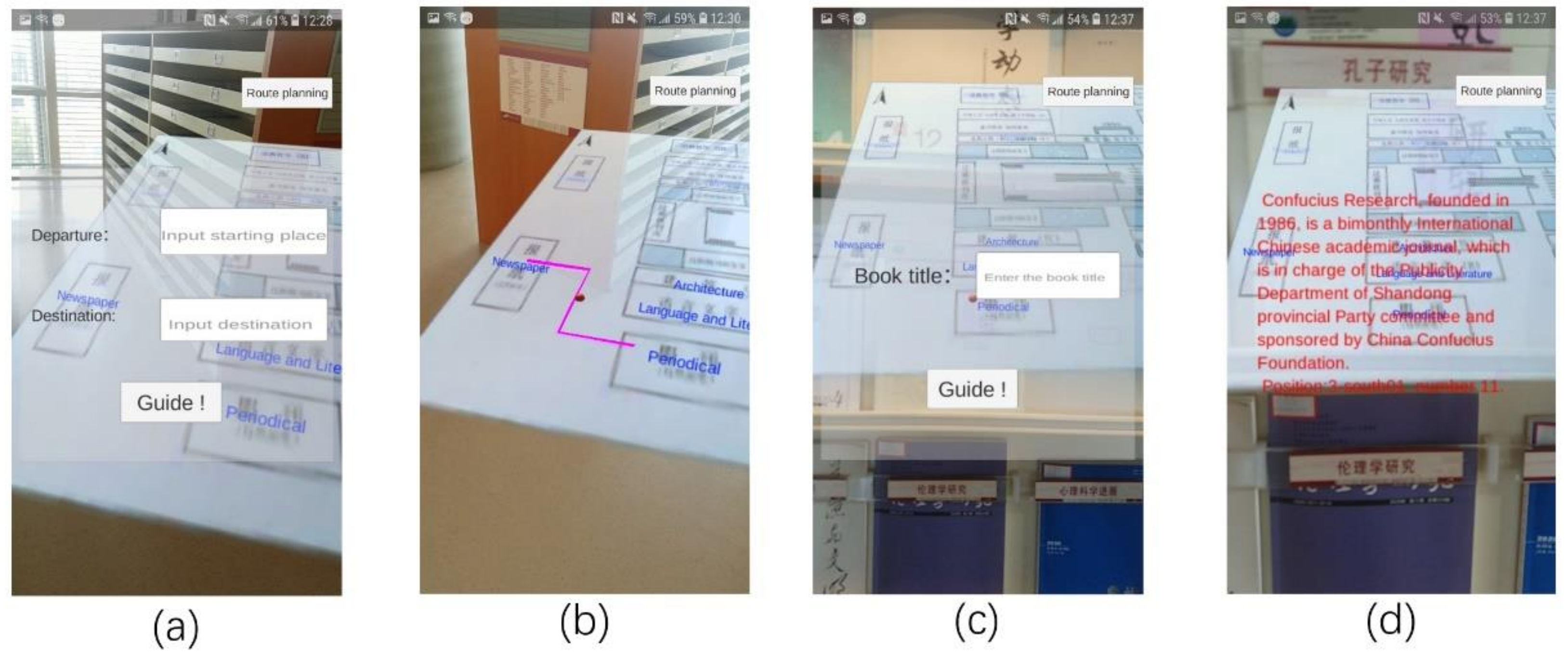
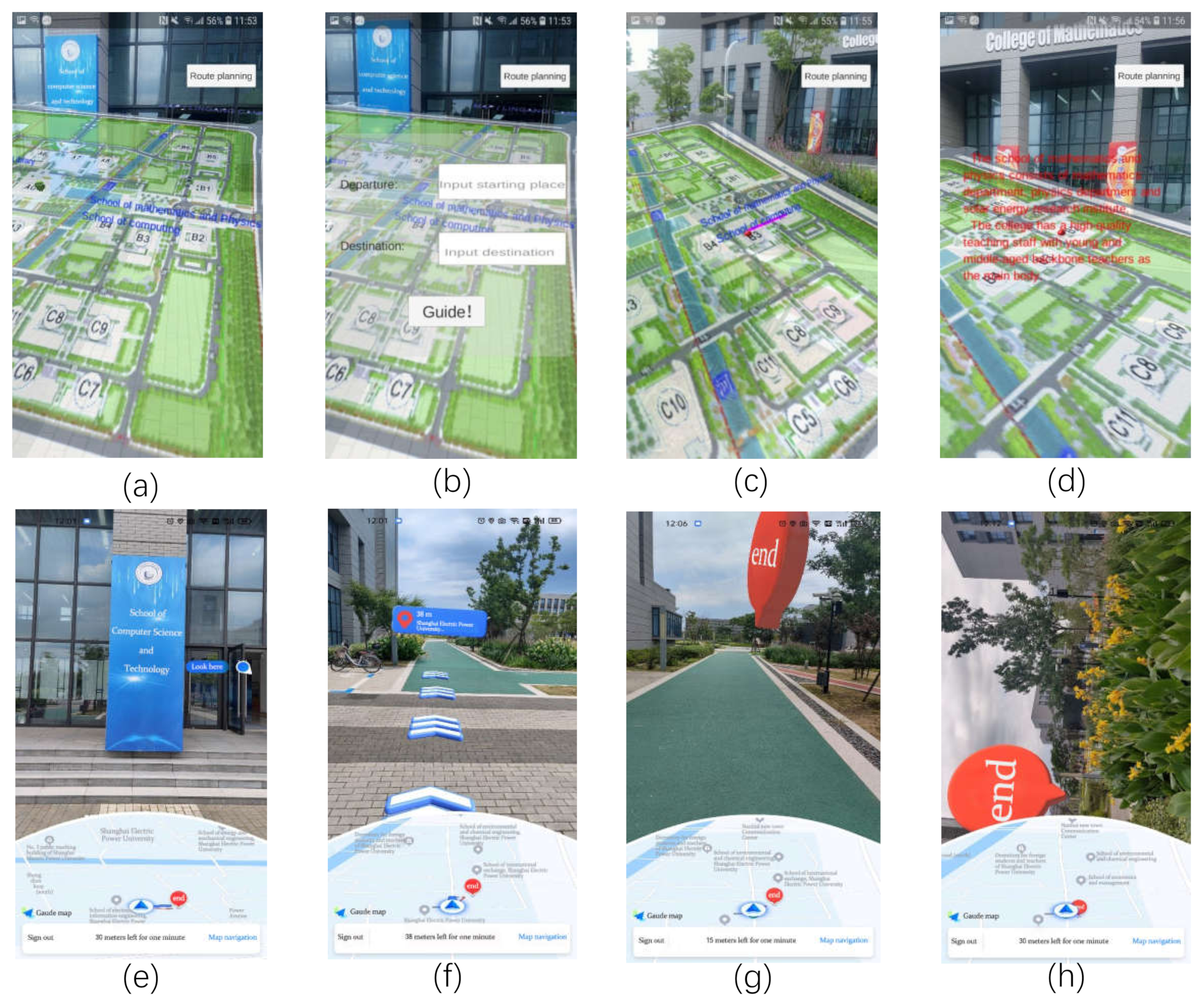
During the whole process, the system superimposes the virtual route into the real environment by the technology of AR. Meanwhile, 3D augmented information is integrated with the real buildings by using the camera in order to enhance the user’s sensory experience.
(2)
The navigation system uses the visual odometry and inertial sensors for the localization and map building in order to solve the problem that the GPS cannot provide users with satisfactory accuracy localization in outdoor situations. Therefore, the system can provide high precision navigation in both indoor and outdoor environments.
(3)
The system uses Unity as the development platform. By writing corresponding scripts, it can design plentiful human-computer interaction functions according to the different scenarios and user needs.
(4)
The system can provide users with a large number of augmented reality content through the database such as 3D text, voice, video and other information so that users will have an interactive feeling during navigation.
The remainder of this article is organized as follows: Section 2 describes the related work. Section 3 presents key technologies. Section 4 introduces the system implementation. Section 5 presents system test and result analysis. The evaluation is presented in Section 6. Section 7 provides conclusions.

2. Related Work

The existing campus navigation systems can mainly be divided into two types: the traditional 2D navigation system and the AR based navigation system. Most of the traditional 2D plane navigation system is based on the Internet of Things technology, and these navigation systems utilize GPS technology for localization. Based on the Baidu Map API, Pan et al. [1] uses the campus of Yunnan Normal University as an example and implemented the function of electronic maps by using data provided by Baidu maps. Their systems realized the functions of self-location, location search and route query. Shen et al. designed a campus navigation app based on the Android platform [5], which used the spatial information of the Lingang campus of the Shanghai Maritime University as basic data. This navigation system implemented the functions such as campus information query, campus panorama display and campus route navigation. Vaibhav Anpat et al. designed a Google Maps application also based on the android platform [6]. The system first calculates the shortest path from the current location to the target location and updates surrounding environment information in real time. When using the above-mentioned systems in order to conduct a tour of campus buildings, the introductions to the buildings are presented by using 2D plane text, pictures or other information, resulting in unintuitive navigation effects. Furthermore, the functions relying on navigation services are provided by third-party platforms, and route planning is also limited.
The navigation systems based on augmented reality technology can be divided into outdoor navigation system and indoor navigation system according to different scenarios. Yu et al. [7] designed an outdoor campus navigation system that combines augmented reality technology and GPS localization. The system used augmented reality technology to render 3D animation models and video playback, and it also has the ability to recognize images of animals and plants. For cultural activity, Pei et al. [8] designed a campus touring system based on AR technology and smart phones, which contains the built-in GPS, camera, WiFi and a digital compass. Since the above-mentioned system is based on GPS localization service, it is suitable for outdoor navigation instead of indoor navigation. A. H. Sayyad [2] designed an offline augmented reality system for the University of Pune in India. The system can provide users with good visualization, high information security and real-time campus navigation information services through the offline campus booklet. However, the system only presents 3D targets and their corresponding parameter information and has little human-computer interaction methods, resulting in a poor user experience. Lin et al. [9] designed a campus navigation system by using augmented reality technology and proposed a virtual terrain modeling interface with deep learning functions in order to improve the target recognition capabilities. Dutta et al. [10] designed a system called Divya-Dristi, which can help visual-impaired individuals navigate in familiar environments (e.g., university campus). The system uses cloud-based geospatial data storage to store key location information and answer the location queries. Moreover, the system utilizes the sonar sensor module in order to create sounds and tactile alarms to assist visual-impaired users in avoiding obstacles that may occur during outdoor navigation. Ricky Jacob et al. proposed a Web-based multilingual campus guidance system [4], which utilizes OpenStreetMap’s Cloud-made Web Map Lite API to create the interface. The system uses indoor corridors or outdoor sidewalks between various buildings and points of interest (POI) in order to generate the shortest sidewalks. However, these systems need to be worked in a networking environment, and some of them need to be worked in the campus intranet and limited to authenticated and authorized users.
In terms of indoor navigation, P. Verma et al. used the Unity 3d framework to build an AR-based mobile application for indoor scenes [18]. This application uses augmented reality technology in order to help people navigate complex buildings. C. G. Vallerand et al. designed a system that uses micro-localization algorithms in order to track Internet of Things (IoT) devices in a large indoor environment [19]. This system can precisely locate devices within 3 m2, and it can propose effective routes for technicians in seeking objects in large indoor environments. However, when the system is applied to an outdoor environment, the accuracy of the location is greatly reduced as the scope of navigation increases. Therefore, it is necessary to develop a system that integrates indoor and outdoor real-time localization and provides a good look and feel experience for users [20].
Jiang et al. [21] proposed a navigation system and a handheld navigator for both indoor and outdoor environments. This system used GPS for outdoor navigation. For indoor environment where the GPS cannot be applied, it used sensors and radio frequency identification (RFID) terminal devices. However, terminal devices need to be deployed in advance, which not only increases the cost but also has limitations. Vanclooster et al. [22] combined indoor and outdoor navigation in route planning. Wang et al. [23] used OpenStreetMap data to integrate indoor and outdoor route planning for pedestrians. Croce et al. [24] proposed an indoor and outdoor navigation system for visually impaired people. It exploits the use of both the inertial sensors and camera integrated in the smartphone as sensors. The system integrates computer vision and dead-reckoning techniques for tracking and navigation. However, these systems [25,26,27,28] are not based on augmented reality technology; thus, this results in deficiency in rich interactive information and 3D prompted information during navigation.
In order to solve the problems of existing campus navigation systems, an ARCore-based augmented reality campus navigation system (AR-CNS) was designed in this paper. Firstly, the proposed campus navigation system uses the ARCore to realize the augmented reality function of 3D information and real scene. Secondly, the visual inertial ranging algorithm is used for the localization and map building of mobile devices in real time. Finally, Unity 3D, as a development platform, is used to design rich scripts in order to increase user’s autonomy and enjoyment during the navigation process.

3. Key Technology

The proposed navigation system uses visual odometry and inertial sensors for localization and map building in order to solve the accuracy problems that are induced by GPS in indoor situations. Therefore, the system can provide navigation with high precision in both indoor and outdoor environments.

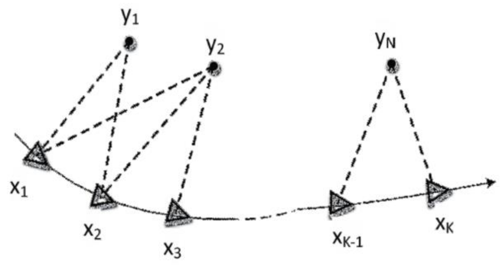
3.1. VIO State Estimation
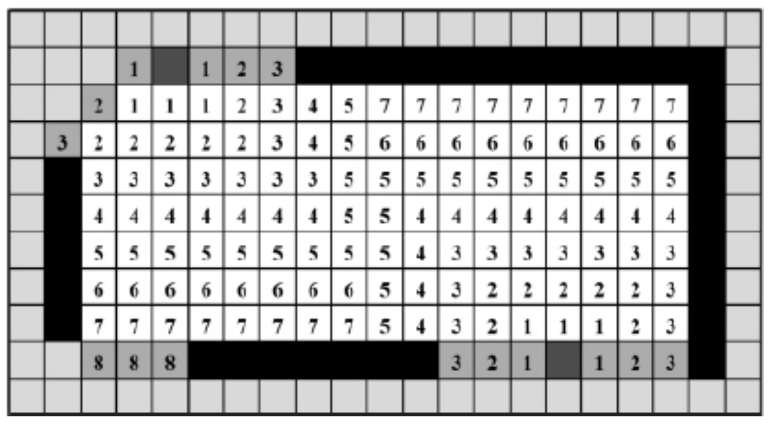
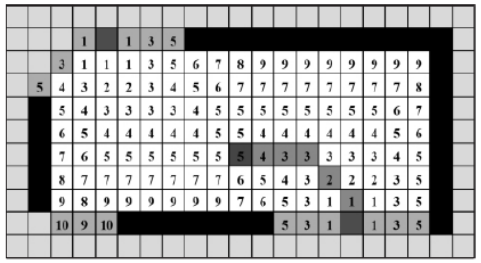
The visual inertial odometer (VIO) is for realizing localization and navigation of the mobile device by integrating the inertial measurement unit (IMU) data with vision. It has good performance in indoor navigation. Its advantages are strong complementarity, high localization accuracy and good robustness. It has a wide application range and good application effect in the combined indoor and outdoor navigation system. The VIO method uses the filtering-based extended Kalman filter [21] method in this paper. In essence, it can be understood as a state estimation problem [22].
The observation equation and the motion equation are usually used to describe the moving carrier. The relationship between the camera and the marker is shown in Figure 1.
In Figure 1, the small black dot represents the marker, and the triangle represents the pose of the camera. At each pose, the markers within its range can be observed. Usually, the sensor collects surrounding information through time intervals. Here, a period of time is divided into discrete moments, denoted as t = 1 , 2 , , k . The parameter X is used to represent the pose of the carrier itself; thus, x 1 , x 2 , , x k constitutes the trajectory of the carrier. Assuming that there are n markers in total denoted as y 1 , y 2 , , y n , the mathematical model abstracted from sensor movement and observation is defined as Equation (1):
x k = f x k 1 , u k + ω k 1
where u k represents the input value of the sensor, and ω k 1 denotes motion noise.
When the carrier observes y j at the position of x k , the function of this process can be defined as follows:
z k , j = g y j , x k + v k , j
where v k , j is the observation noise. Equation (1) denotes the equation of motion, and Equation (2) denotes the equation of observation. The existence of noise obeys Gaussian distribution. The estimation of state is composed of real value and noise value, which also obeys Gaussian distribution.
In order to express the motion equation and observation equation concisely, let s k represents the unknown quantity at time k , and z k represents the measured value at time k ; thus, s k = x k , y 1 , y 2 , , y m . The motion equation and observation equation are defined as follows.
s k = f s k 1 , u k + ω k 1 z k = g s k + v k
By using data from past 0 to k − 1, the current state distribution can be estimated by Bayesian formula, which is defined as follows.
P s k s 0 : k , u 1 : k , z 1 : k P z k s k P s k s 0 : k , u 1 : k , z 1 : k 1
In Bayesian formula, the left part is called posterior probability, the first term on the right denotes likelihood and the second term denotes prior probability. According to the moment s k 1 , the conditional probability can be expanded as follows.
P s k s 0 : k , u 1 : k , z 1 : k 1 = P s k s k 1 , s 0 , u 1 : k , z 1 : k 1 P s k 1 s 0 , u 1 : k , z 1 : k 1 d s k 1
For subsequent processing, there are two general choices. One is to use the filter-based method, and the other is to use the nonlinear optimization method. In this paper, the extended Kalman filter is selected as the representative filter-based method. According to the first-order Markov property, the state at time k is only related to the state at time k − 1, and it is independent of the previous state. Based on this assumption, the state of the next moment can be deduced from the state estimation at the current moment.

3.2. Area Learning

During navigation, the following situations are unavoidable. For example, there are no obvious landmarks around such as blank walls, floors and all-white corridors. It is difficult for the ARCore to perform tracking without obvious feature points, and the application displays “Lost tracking, waiting…”. In order to tackle such situations, the area learning module is applied. Area learning allows the device to view and remember the main visual features of the region it has passed before, including edges, corners and other unique features. Therefore, the device can recognize the same area later.
The area learning is realized by using the boundary extraction method. The system collects boundary information from the current map and simultaneously calculates the optimal boundary. The midpoint of the optimal boundary is used as the next moving target of the mobile device, thus planning the global path. The mobile device periodically extracts the boundary in the unknown area. The specific implementation is divided into the following steps.
(1) The boundary of the current map and the unknown blank boundary adjacent to it is scanned. The known region is the current grid area. In order to eliminate collision, the boundary mesh smaller than the diameter of the mobile device itself is eliminated, as shown in Figure 2.
(2) The midpoints of all remaining boundaries are collected and used as the next target point to be confirmed. The midpoints of all remaining boundaries are shown as the black grid in Figure 2. Each target point as the center is taken, the grid that has been explored through the Flood-fill algorithm is filled [23] and the distance transformation value c o s t d t i of the grid is calculated at the same time.
(3) In order to avoid errors caused by mobile device collision, the obstacle transformation value c o s t o t i is calculated for each grid. The obstacle transformation value is calculated according to Equation (6):
c o s t o t i = ( X Ω i ) 3 , if   Ω i X 0 , o t h e r w i s e
where Ω i is the distance between the blank grid and the obstacle grid; X is a constant, which is determined by the radius of the mobile device. The obstacle transformation value c o s t o t i of each grid is shown in Figure 3.
(4) The distance transformation value c o s t d t i of each grid and the obstacle transformation value c o s t o t i are added simultaneously, and the sum is recorded as the exploration cost value of each grid, as shown in Figure 4. By using the current position of the mobile device as the reference point, the mobile device explores the direction of the target point with a large decrease in exploration cost. The grids that the mobile device passes are the global path learned by the mobile device.
(5) The Path tracing algorithm [24] directs the mobile device according to the learned global path until the effective boundary cannot be extracted in the region.
In order to improve the accuracy of the predicted trajectory, area learning is applied in ARCore to correct the inherent “drift” of the SLAM technology; meanwhile, it can accurately locate its own coordinates within the learned region. The initialization of Tango service is built on ARCore by using the method of _GetSessionTangoConfiguration. The area learning option is activated with the following code:
tangoConfig.areaLearningMode = UnityTango. AreaLearningMode. CloudAreaDescription.

4. System Implementation

At present, there are two major development tools for augmented reality: Apple’s ARKit and Google’s ARcore. ARKit is a development kit for iOS apps, while ARcore is a development kit for Android apps. Both technologies use the following features to integrate virtual content into the real world: motion tracking, environmental understanding and light estimation. Obviously, there are differences in capability between ARKit and ARCore. ARCore tracks more feature points; thus, it expands the mapped area more quickly than ARKit. However, ARKit detects horizontal and vertical surfaces more accurately than ARCore. If the app is developed by ARKit, it is necessary to install Xcode first because ARKit can only run on MacOS. Considering that ARcore SDK can be applied to Android 7.0 system and above without special hardware support, the proposed augmented reality campus navigation system is developed based on ARCore.

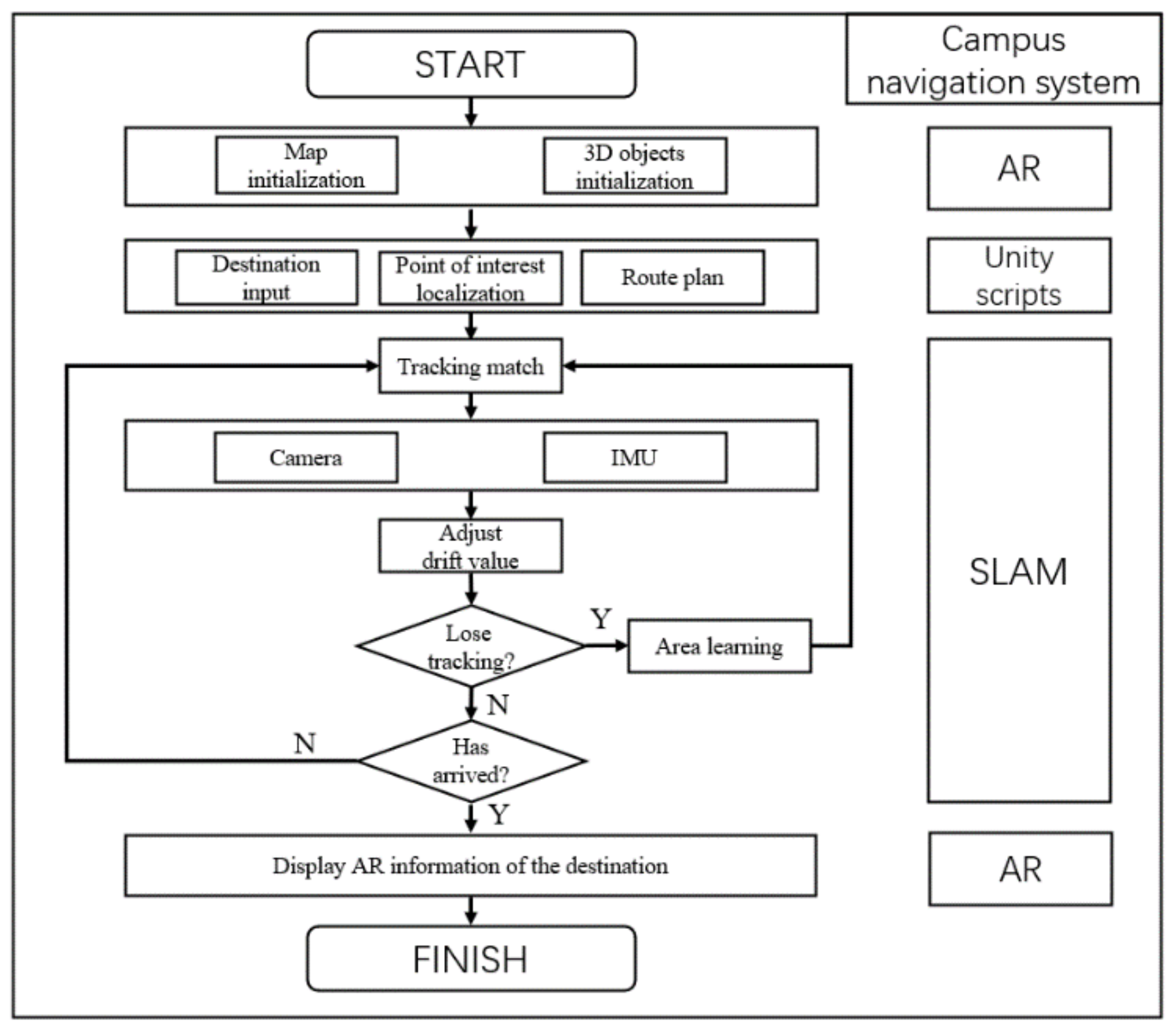
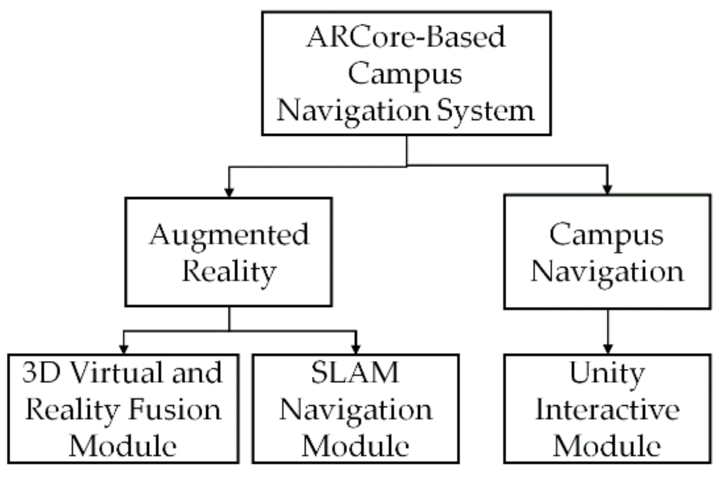
4.1. The Logical Structure of the System

By analyzing the user’s needs and the main framework of the mobile AR navigation system, the logical architecture of the proposed system is shown in Figure 5. Firstly, the system obtains scene information from the current video stream by utilizing the mobile phone camera and sensor in order to finish map initialization and 3D objects initialization. Secondly, the system prompts users to enter the starting place and destination. Thirdly, the system transmits corresponding information of the starting place and destination to the server. Fourthly, the server sends transmitted information to the mobile phone after querying the database. Later, the mobile phone plans the path according to the coordinates of the interest point. During the process of navigation, the system adjusts the drift value for tracking match. If it loses tracking, area learning is used to recover from this situation. Finally, when the user arrives the destination, it superimposes the enhanced information with the interest point in order to achieve the virtual reality fusion effect.

4.2. The Design of System Module

This system is an augmented reality application system based on mobile terminals, which provide navigation to users in the form of 3D maps. Thus, it can provide users with good sensory experience by combining augmented reality information. The main modules of this system can be divided into the 3D virtual and reality fusion module, SLAM navigation module and Unity interactive module. Each module is designed with the principle of high cohesion and low coupling. The details of the main modules of the system are shown in Figure 6.

4.2.1. SLAM Navigation Module

In the actual scene, the theoretical basis for estimating the motion state of the mobile device is the motion equation, which is based on the state of the previous moment and the motion of the current moment. The input u s predicts the current motion trajectory. Combined with the sensor, it corrects the motion prediction based on its measurement equation. In the single vision slam, there is no input of motion state; thus, the information provided by the correction equation is limited. After the introduction of IMU data, IMU is used as the motion input u s . The experimental results show that this method can more exactly predict the motion state. The essence of vio algorithm is using motion prediction and a measurement equation for joint prediction.
During the process of system navigation, the real-time navigation information of the camera following the target (anchor) is fed back to the user. The script (HelloARController.cs) used to control tracking parameters in Google ARCore development package is modified, which includes text components that are used to display messages publicly and the camera that follows target. These common fields are filled by dragging and dropping the corresponding objects from the scene hierarchy, and the QuitOnConnectionErrors method is also modified. Meanwhile, the CameraPoseText component is used to display the current message on the screen.
The campus navigation system needs to match the distance of the camera moving in the real world with the distance of the camera moving in the 3D map in real time. Firstly, the Update() method was rewritten to reserve the position and pose of the last camera in order to calculate the incremental position of the translation vector from frame to frame, which is the translation task applied to the sphere when walking. Secondly, when the user’s position is displayed on the plane, any translations on the y-axis are removed to ensure that the tracking point will not be lower than the plane when the users are holding the mobile phone camera for campus navigation. At the same time, the campus navigation system tries to keep the tracking point stable when moving. The tracking type was set to “Position Only” in ARCoreDevice and the position and rotation information was provided by the Frame. Posing was used to apply position information to the translation of the sphere from frame to frame in the FollowTarget script. In order to render the rotation of the anchor point in the 3D map consistent with the rotation of the mobile phone, the rotation was set to the third-person camera, which is always behind the sphere. The player settings were set according to Google’s recommendations as follows:
  • Other Settings > Multithreaded Rendering: Off;
  • Other Settings > Minimum API Level: Android 7.0 or higher;
  • Other Settings > Target API Level: Android 7.0 or 7.1;
  • XR Settings > ARCore (Tango) Supported: On.

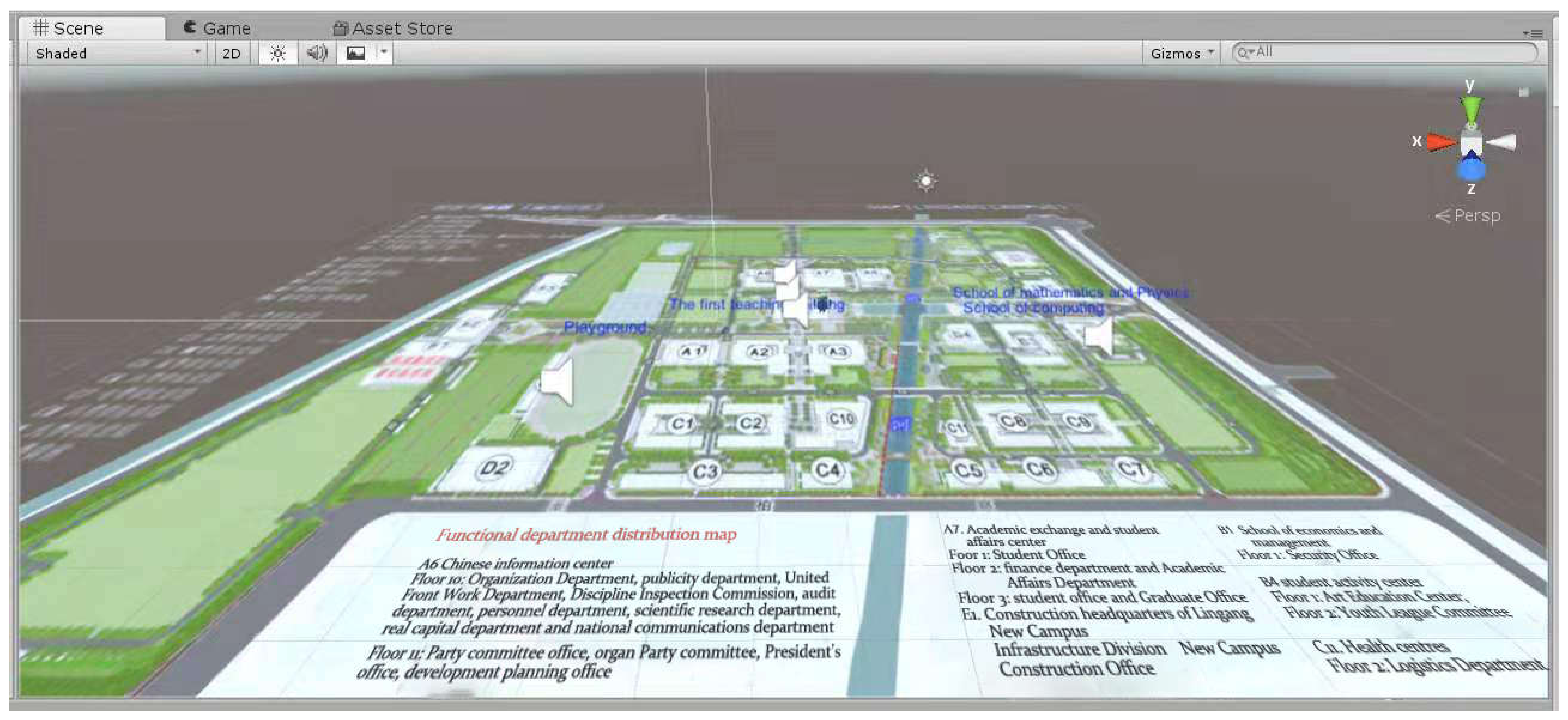
4.2.2. 3D Virtual and Reality Fusion Module

The three-dimensional virtual and reality fusion module is a very important module in AR campus navigation system. The campus guide needs a map of the navigation area. In order to scale the map, when creating a texture map, the image needs to be cropped into a rectangle. It is common to create a 3D plane and to assign an image map such as an albedo texture. Meanwhile, the plane needs to be scaled in order to ensure that the distance in the map is equal to the actual distance. When the proposed system is running, it collects the real environment information through the mobile camera and stores it in the memory to build the map. The tracker uses keyframe information to match the real world to a virtual 3D map. Then, the VIO algorithm and tracker are used to complete the perception of the environment. However, it was found that the more the mobile device moves in the actual scene, the larger the constructed map resulted in the experiment, which often results in poor tracking results and data loss. This kind of problem has been well solved by ARCore. ARCore creates anchors to repair the map content. Multiple anchors can be set in order to expand the range of physical areas to ensure real-time and accuracy.
In order to realize the blending effect of the 3D map and the real scene, the texture of the plane image is set to semi-transparent, and the shader of the plane material is set to the traditional “Transparent/Diffuse”. It is worth noting that “BackgroundMaterial” is marked to “None” in order to avoid rendering the camera source. Due to the background in the camera options, the real scene content shot is clearly presented by the camera during navigation.

4.2.3. Unity Interactive Module

In order to increase human-computer interaction during the system navigation, the anchor point is set as the Collider Component. Different colliders are designed according to different campus buildings. There are many kinds of collider components, such as Box Collider, Capsule Collider, etc. These colliders are used in different scenarios, but they must all be added to GameObject. The trigger needs to check the selection box of the IsTrigger property in the collider component in the Inspector.
In this application, the tracking red balls and buildings are the collision objects. In order to enhance the user’s experience in the navigation process, the OnTriggerEnter() function is set to determine whether it is the target building. When the condition becomes true, it is displayed by augmented reality information including text, voice, 3D route, etc. OnTriggerExit() is a function for exiting collision detection and clearing text information, which switches voice playback off while other settings are set up.

5. System Test and Result Analysis

Up to July 2021, Shanghai University of Electric Power (SUEP) has 13 schools/departments with more than 13,000 full-time undergraduates and postgraduates. The SUEP faculty includes more than 1000 full-time teachers. It also has two campuses: The Yangpu campus and Lingang campus which covers an area of over 800,000 m2, including more than 40 buildings and 20 different roads. In modern campuses, campus navigation systems are often implemented to provide navigation services for visiting staff and freshmen. The mobile ARCore-based augmented reality campus navigation app is designed to integrate indoor and outdoor navigation. The experimental site used was the Lingang campus of SUEP, and its layout is shown in Figure 7.

5.1. Outdoor Campus Map Testing

In the outdoor mode, the camera of the mobile phone is always working. The navigation mode is presented to the user in the form of real scenes and 3D maps, as shown in Figure 8a. The user’s perspective is located on the top of the 3D map and can overlook and browse the architectural planning of the whole campus. Three-dimensional road signs are suspended above the location of the corresponding building to distinguish the location of the building. A dialog box appears in order to input the starting location and destination when users click the “Route Planning” button, as shown in Figure 8b. After entering the starting place and destination, the “Guide!” button is clicked in order to start route planning. After clicking navigation, a red path is displayed on the map, representing the best path plan from the starting place to the destination. The red ball represents the current location. Importantly, the initial synchronization function needs to be open in order to synchronize the initial position of the device camera with the position of the sphere on the map. As shown in Figure 8c, the initial position is on the road between the College of Computer Science and Technology and the College of Mathematics and Physics, which faces the library. Therefore, the forward vector of the sphere needs to be consistent with the user’s forward direction. The initial location is the location of the phone camera, but not the location of the user. The phone is kept at a distance of about 50 cm from the line of sight. Once the initial position is adjusted correctly, the on-screen message “Lost tracking, Waiting...” disappears. At this point, the app will track the user’s location on the map more accurately. In order to easily and automatically synchronize the location information in the map, the buildings are marked on the 3D map. Markers can also help users correct the direction of movement during walking. When the red ball reaches the destination, the path automatically disappears, and a voice prompt and augmented reality information pop up, as shown in Figure 8d. After the navigation process is completed, the user can select “Path Planning” for a new round of navigation.
At present, the most commonly used maps are Google map, Apple map, Baidu map and Gaode map. Google map can be used abroad; unfortunately, it cannot be used in China. Apple map is only for the IOS system and does not support other models of mobile phones. Baidu map has the largest amount of map contents. On the other hand, Gaode map is a leading provider of digital map content, navigation and location service solutions in China. Its high-quality electronic map database has become the core competitiveness of the company, and its road information is the most accurate. On 14 August 2020, Gaode map announced the launch of AR virtual live navigation function. The AR function combines the mobile phone camera with the user’s location, direction and other information in order to show information points in a more intuitive manner. In order to prove the accuracy of localization of the proposed system, ARCore system is compared with Gaode outdoor AR navigation system. First, the destinations and click AR navigations of Gaode map App are entered, as shown in Figure 8e. When the mobile phone is erected, it will enter into AR navigation mode. The route of the guide is superimposed into the real scene, and the location and distance of the destination will be marked as shown in Figure 8f. According to the guide route in Figure 8g, the terminal mark will become larger as the destination becomes closer. However, the accuracy of outdoor AR navigation of Gaode is passable. When the Gaode app shows that the destination has arrived, the actual destination is on the right side of the terminal mark, and the straight-line distance is about 30 m, as shown in Figure 8h. On the other hand, the actual destination is the building at the top of Figure 8h. Therefore, it is clear that the outdoor AR navigation proposed in this paper has higher location accuracy since the proposed app combines more rich components and integrates voice, 3D text, 3D objects and other information into the buildings during AR navigation.

5.2. Indoor Library Floor Map Test

The library was selected as the indoor test site. In the daily campus life, the library is a frequent place for students to study and to examine literature. Before looking up the books, students often need to enter the title of the book in front of the library search system and to obtain the index number. They then proceed to the floor where the book is located and perform a search according to the shelf number. This process is not only cumbersome but also inefficient in query. Through the augmented reality navigation system, the specific storage location of the books to be borrowed can be found more intuitively and quickly.
When the user arrives at the location of the library through path planning, the system will automatically switch between outdoor and indoor maps, and what is presented is a 3D indoor flat map of the library. The location of each book area is clearly listed on the map. As shown in Figure 9a, it is easier to enter the starting location and destination area in the dialog box, and the “Navigation” button is clicked in order to start route planning. The system will accurately mark the user’s current location on the 3D map according to the entered starting place, and the red ball is used in order to locate it. At the same time, a red path will be displayed, which represents the best path from the starting point to the destination as shown in Figure 9b. Before navigating, an initial synchronization is also required in order to synchronize the initial position of the device camera with the position of the sphere on the map. It is also important to first place the sphere in the position and direction of the navigation and to navigate according to the planned route. When arriving at the corresponding area, the navigation system will automatically pop up a book query dialog box, as shown in Figure 9c. The book query function is connected to the school’s book database. When the user enters the title of a book and clicks on the query, the system calls the database to query the specific location of the book as the title of a book is typed. After the system recalls book information, basic introduction and location information of the book will be displayed on the screen of the mobile phone, as shown in Figure 9d. The user can quickly locate the location of the book in combination with 3D text. At the end of this navigation, the “route planning” button is clicked again to start the next round of regional navigations in the library.
The proposed system shows great scalability and flexibility for indoor navigation. As long as there are clear 2D plans of other libraries, the library navigation of different schools can be realized by replacing the mapping shader. There are great advantages in integrating indoor and outdoor campus navigation in ARCore as shown in Figure 8 and Figure 9. Compared with Gaode and other navigational software, the advantage of the app is that it takes the predefined indoor map as reference and realizes the indoor navigation accurately. It also solves situations in which GPS cannot be applied in the indoor navigation. In order to further compare with the previous AR navigation, the system shows powerful features in various scenarios, such as the location of large regional venues, exhibition stalls and so on. The system also has the advantages of its ARCore SDK and Unity development platform, which combines rich components and integrates voice, 3D text, 3D objects and other information into the whole AR navigation by script writing. Thus, ARCore can achieve good human-computer interaction experience.

6. Evaluation

In order to measure the effectiveness of this proposed navigation system, a small sample of students in SUEP was chosen for the system evaluation. The purpose of this test is to determine whether this system could facilitate the effectiveness and usability of learning on campus compared with traditional medias such as Gaode map or Internet media. An online open-ended questionnaire is utilized for data collection.

6.1. Participants and Test Design

Random-chosen participants numbering 120 from the College of Computer Science and Technology in SUEP are invited for this system evaluation. Participants are divided equally into four groups named Group A/B/C/D, as shown in Table 1. Each group consists of 30 students, respectively. In particular, freshmen made up half of the participants in Group C and D. Two different navigation systems were applied in Group A/B/C/D. For Group A and C, the participants were told to use the AR outdoor campus navigation system and were trained to use the mobile client app. On the contrary, participants in Group B and D were told to use the AR indoor campus navigation system and did not received any training for using the mobile client app.
The evaluation session followed preprocessing and lasted one day. At the end of evaluation, all participants in Group A, B, C and D completed the open-end questionnaire online. The survey includes questions about essential personal information, objective questions on system effectiveness and usability and subjective questions. Essential personal information is used to evaluate the general experience and habits of current students. Objective questions allow users to compare this system with traditional medias that they have used before and to validate the actual effect and usability. For subjective questions, participants are encouraged to provide their own suggestions, benefits and limitations regarding this system.

6.2. Results and Analysis

For the purpose of determining the differences between the proposed mobile AR-based system and traditional media, five levels of the Likert rating scale (Extremely satisfied (5 score), very satisfied (4 score), somewhat satisfied (3 score), not so satisfied (2 score) and not at all satisfied (1 score)) were applied to each assessment question. After the students finished the questionnaire, the agreement rate of user experience is calculated. For example, fourteen people chose somewhat satisfied (3 score), and sixteen people chose very satisfied (4 score). Considering that the max score is 5 and that there were 30 people in total, the performance score is computed as 14 × 3 + 16 × 4 / 30 × 5   71 % . Statistical tests were also used to search for differences between four different groups. Here, the t-test is used to judge whether significant differences exist between group A and group C for outdoor navigation. As showed in Figure 10a, for outdoor campus navigation, five conclusions are obtained as follows:
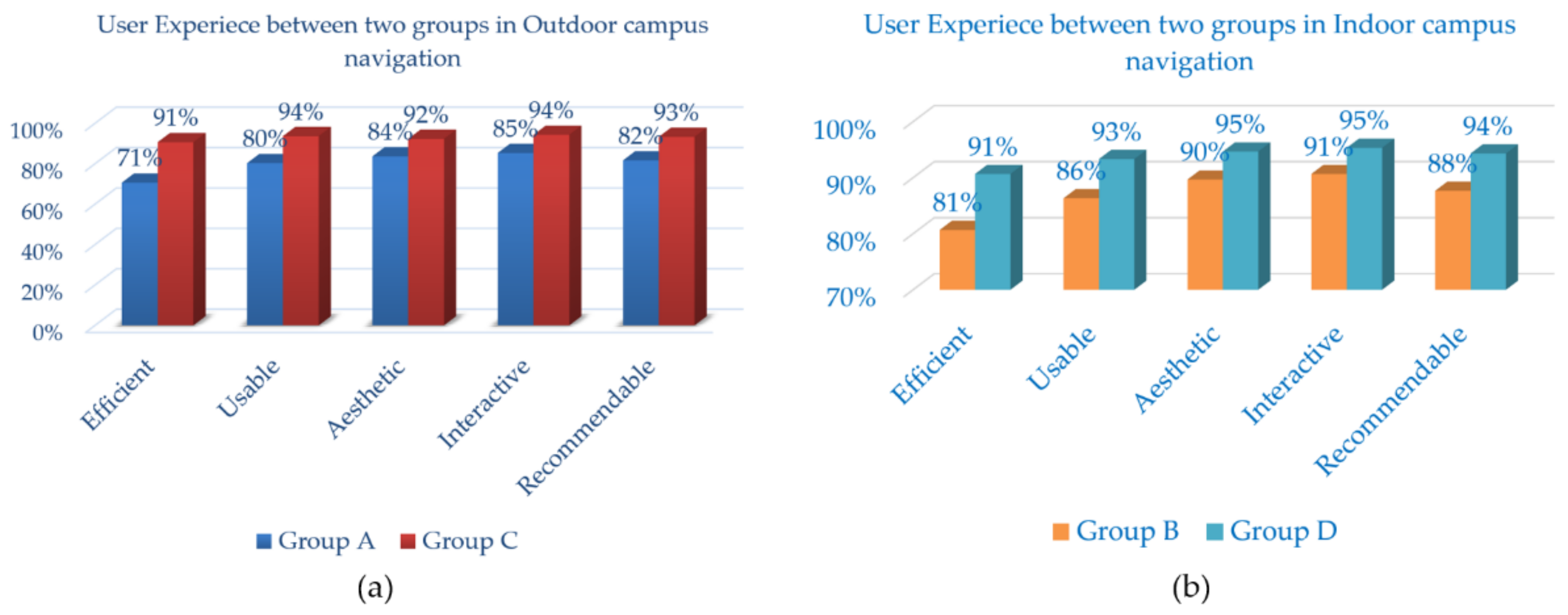
  • It is encouraging that more than 71% of participants in each group agreed that the proposed system was better than conventional media in all five aspects;
  • Freshmen possess superior evaluation than senior students for outdoor campus navigation in all aspects, which may be attributed to the fact that freshmen are not as familiar with the campus layout, resulting in increased reliance on the outdoor campus navigation system;
  • The demand for the outdoor campus navigation system was not urgent by the senior students, which may be due to the fact that they are more familiar with the campus layout and are not completely dependent on the navigation system.
  • The p-values of the attitudes towards aesthetic and interactive for group A and C are greater than 0.05, suggesting that the difference of the above aspects between group A and C is insignificant;
  • The p-values of the attitudes related to efficiency, usability and recommendability for group A and C are greater than 0.01 and smaller than 0.05, indicating that the difference of the above aspects between group A and C is significant.
Considering that traditional media (e.g., Gaode map) cannot provide indoor navigation, the proposed mobile AR-based system is more practical. Meanwhile, The t-test is also used to judge whether significant differences exist between group B and D for indoor navigation. As shown in Figure 10b, four conclusions are obtained as follows for indoor campus navigation:
  • It is encouraging that more than 81% of participants in each group agreed that the proposed system is better than conventional media in all five aspects;
  • Not only freshmen but also senior students have higher evaluations for indoor campus navigation with respect to all aspects. Although the senior students are more familiar with the campus layout, they are not very clear about the indoor distribution, such as the exact location of the magazines and books in the library. Therefore, the differences between freshmen and senior students for the demand of indoor campus navigation system are negligible.
  • The p-values of the attitudes towards usability, aesthetics, interactiveness and recommendability for group B and D are bigger than 0.05, showing that the differences relative to the above aspects between group B and D are insignificant.
  • The p-value of the attitude towards efficiency for group B and D is greater than 0.01 and smaller than 0.05, indicating that the difference relative to the above aspect between group B and D is significant.

7. Conclusions

In order to solve the problem in which the route planning function in 2D/3D campus navigation systems in the market cannot simultaneously process indoor and outdoor localization information, this paper designs an ARCore-based augmented reality navigation system that integrates indoor and outdoor campus navigation. This design effectively solves the problems of the traditional campus navigation system, such as inflexible decision-making, inconvenient query and weak sense of architectural space. It also provides a technical solution for the intelligent management of university campus, which can better serve the construction of intelligent campus. Compared with the AR outdoor navigation system of Gaode, the proposed ARCore system can achieve more precise outdoor localization by deploying the visual inertia odometer on the mobile phone and realizes the AR function of 3D information and real scene; thus, this also enriches the user’s interactive experience. Through four groups of student tests and system evaluations, experimental results show that the system could facilitate the effectiveness and usability of learning on campus when compared with traditional systems.

Author Contributions

Formal analysis, H.Z.; Methodology, L.G.; Software, H.Z.; Validation, L.P.; Writing—original draft, F.L. and J.C.; Writing—review and editing, L.G. and J.C. All authors have read and agreed to the published version of the manuscript.

Funding

This research received no external funding.

Institutional Review Board Statement

Not applicable.

Informed Consent Statement

Not applicable.

Data Availability Statement

The implemented code that supports the findings of this research are openly available at https://github.com/zhouhao1011-oss/Campus-Navigation-System (accessed on 12 August 2021).

Conflicts of Interest

The authors declare no conflict of interest.

References

  1. Anning, P.; Kun, Y. Design and Implementation of Campus Comprehensive Information Service System Based on Baidu Map API. Comput. Knowl. Technol. 2016, 12, 72–74. [Google Scholar]
  2. Sayyad, A.H.; Shinde, S.A. Augmented Reality Based Mobile Tour Guide System. Int. Res. J. Eng. Technol. 2016, 3, 406–412. [Google Scholar]
  3. Li, Z.G.; Qi, G.L.; Hu, W.K.; Ma, X.Y.; Guo, Q.S. Application of Augmented Reality in Campus Navigation. In Proceedings of the IEEE 6th International Conference on Intelligent Computing and Signal Processing (ICSP 2021), Xi’an, China, 9–11 April 2021; pp. 889–893. [Google Scholar]
  4. Jacob, R.; Zheng, J.; Ciepłuch, B.; Mooney, P.; Winstanley, A.C. Campus guidance system for international conferences based on OpenStreetMap. In Proceedings of the International Symposium on Web and Wireless Geographical Information Systems, Maynooth, Ireland, 7–8 December 2009; pp. 187–198. [Google Scholar]
  5. Wenrui, S.; Liansun, Z.; Zhen, Y. School based on Android platform Garden guide software design. Electron. Des. Eng. 2012, 20, 26–28. [Google Scholar]
  6. Anpat, V.; Shewale, A.; Bhangale, Y. Campus Navigation on Android Platform. Int. J. Sci. Technol. Eng. 2016, 2, 452–458. [Google Scholar]
  7. Yu, K.-M.; Chiu, J.-C.; Lee, M.-G.; Chi, S.-S. A mobile application for an ecological campus navigation system using augmented reality. In Proceedings of the International Conference on Ubi-Media Computing (UMEDIA), Colombo, Sri Lanka, 24–26 August 2015; pp. 17–22. [Google Scholar]
  8. Pei, L.S.; Cai, S.; Shi, P.F. Mobile Campus Touring System based on AR and GPS: A Case Study of Campus Cultural Activity. In Proceedings of the 21st International Conference on Computers in Education (ICCE 2013), Denpasar Bali, Indonesia, 18–22 November 2013; pp. 518–526. [Google Scholar]
  9. Lin, C.-H.; Chung, Y.; Chou, B.-Y.; Chen, H.-Y.; Tsai, C.-Y. A novel campus navigation APP with augmented reality and deep learning. In Proceedings of the IEEE International Conference on Applied System Invention (ICASI), Chiba, Japan, 13–17 April 2018; pp. 1075–1077. [Google Scholar]
  10. Dutta, S.; Barik, M.S.; Chowdhury, C.; Gupta, D. Divya-Dristi: A smartphone based campus navigation system for the visually impaired. In Proceedings of the Fifth International Conference on Emerging Applications of Information Technology (EAIT), Kolkata, India, 12–13 January 2018; pp. 1–3. [Google Scholar]
  11. Kourouthanassis, P.E.; Boletsis, C.; Lekakos, G. Demystifying the design of mobile augmented reality applications. Multimed. Tools Appl. 2015, 74, 1045–1066. [Google Scholar] [CrossRef]
  12. Azuma, R.; Baillot, Y.; Behringer, R.; Feiner, S.; Julier, S.; MacIntyre, B. Recent advances in augmented reality. IEEE Comput. Graph. Appl. 2001, 21, 34–47. [Google Scholar] [CrossRef] [Green Version]
  13. Azuma, R.T. A survey of augmented reality. Presence: Teleoper. Vir. Tual. Environ. 1997, 6, 355–385. [Google Scholar]
  14. Chatzopoulos, D.; Bermejo, C.; Huang, Z.; Hui, P. Mobile Augmented Reality Survey: From Where We Are to Where We Go. IEEE Access 2017, 5, 6917–6950. [Google Scholar] [CrossRef]
  15. Kim, D.; Choi, Y. Applications of Smart Glasses in Applied Sciences: A Systematic Review. Appl. Sci. 2021, 11, 4956. [Google Scholar] [CrossRef]
  16. Han, D.-I.D.; Tom Dieck, M.C.; Jung, T. Augmented Reality Smart Glasses (ARSG) Visitor Adoption in Cultural Tourism. Leis. Stud. 2019, 38, 618–633. [Google Scholar] [CrossRef]
  17. Yong, M.; Pauwels, J.; Kozak, F.K.; Chadha, N.K. Application of Augmented Reality to Surgical Practice: A Pilot Study Using the ODG R7 Smart glasses. Clin. Otolaryngol. 2020, 45, 130–134. [Google Scholar] [CrossRef] [PubMed]
  18. Verma, P.; Agrawal, K.; Sarasvathi, V. Indoor Navigation Using Augmented Reality. In Proceedings of the 4th International Conference on Virtual and Augmented Reality Simulations, Sydney, Australia, 14–16 February 2020; pp. 58–63. [Google Scholar]
  19. Charles, G.V.; Simon, R. An indoor navigation platform for seeking Internet of Things devices in large indoor environment. In Proceedings of the 5th EAI International Conference on Smart Objects and Technologies for Social Good, Valencia, Spain, 25–27 September 2019; pp. 108–113. [Google Scholar]
  20. Joaquín, T.S.; Joan, A.; David, R.; Raúl, M.; Sven, C.; Mauri, B.B.; Michael, G.; Joaquín, H. Enhancing Integrated Indoor/Outdoor Mobility in a Smart Campus. Int. J. Geogr. Inf. Sci. 2015, 29, 1955–1968. [Google Scholar]
  21. Jiang, Y.; Fang, Y.; Yao, C.; Wang, Z. A design of indoor & outdoor navigation system. In Proceedings of the ICCAT2011—IET International Conference on Communication Technology and Application (ICCTA 2011), Beijing, China, 14–16 October 2011. [Google Scholar]
  22. Vanclooster, A.; Maeyer, P.D. Combining Indoor and Outdoor Navigation: The Current Approach of Route Planners. In Advances in Location-Based Services; Springer: Berlin/Heidelberg, Germany, 2012; pp. 283–303. [Google Scholar]
  23. Wang, Z.; Niu, L. A Data Model for Using OpenStreetMap to Integrate Indoor and Outdoor Route Planning. Sensors 2018, 18, 2100. [Google Scholar] [CrossRef] [PubMed] [Green Version]
  24. Croce, D.; Giarre, L.; Pascucci, F.; Tinnirello, I.; Valvo, A.L. An Indoor and Outdoor Navigation System for Visually Impaired People. IEEE Access 2019, 7, 170406–170418. [Google Scholar] [CrossRef]
  25. Zhu, S.; Jiang, J. Research on Application of Extended Kalman Filter Algorithm in Navigation. Autom. Appl. 2019, 11, 53–54. [Google Scholar]
  26. Gao, J.C.; Yan, K.D.; Han, B. SLAM estimation method for uncertain model noise parameters. Clust. Comput. 2019, 22, 9425–9434. [Google Scholar] [CrossRef]
  27. He, Y.X.; Hu, T.; Zeng, D. Scan-Flood Fill (SCAFF): An Efficient Automatic Precise Region Filling Algorithm for Complicated Regions. In Proceedings of the IEEE Conference on Computer Vision and Pattern Recognition Workshops, Long Beach, CA, USA, 16–20 June 2019; pp. 1–3. [Google Scholar]
  28. Rostami, S.M.H.; Sangaiah, A.K.; Wang, J.; Liu, X. Obstacle avoidance of mobile robots using modified artificial potential field algorithm. EURASIP J. Wirel. Commun. Netw. 2019, 1, 70–88. [Google Scholar] [CrossRef] [Green Version]
Figure 1. Schematic diagram of carrier movement.
Applsci 11 07515 g001
Figure 2. Extracted boundaries the distance transformation.
Applsci 11 07515 g002
Figure 3. Obstacles transform.
Applsci 11 07515 g003
Figure 4. Exploration transform and the global path.
Applsci 11 07515 g004
Figure 5. Logical structure of ARCore-based campus navigation system.
Applsci 11 07515 g005
Figure 6. The design of the campus navigation system module based on augmented reality.
Applsci 11 07515 g006
Figure 7. Campus plan of Shanghai University of Electric Power.
Applsci 11 07515 g007
Figure 8. Interface collections of the proposed system (ad) and Gaode AR system (eh) in outdoor navigation. (a) Outdoor navigation initialization interface of the proposed system. (b) Navigation information input interface of the proposed system. (c) Navigation interface after route planning of the proposed system. (d) Augmented reality information of the proposed system after arriving at the destination. (e) Outdoor navigation initialization interface of Gaode map after input the destination. (f) Navigation interface after route planning of Gaode map. (g) The terminal mark of Gaode map. (h) Comparison of the terminal mark with the real destination directed by red arrow.
Applsci 11 07515 g008
Figure 9. Interface collections of the proposed system in indoor navigation. (a) Navigation information input interface. (b) Navigation interface after route planning. (c) Enter the book title of the required bibliography. (d) Augmented reality information of the proposed system after arriving at the destination.
Applsci 11 07515 g009
Figure 10. The agreement rate of user experience between four groups in outdoor and indoor campus navigation. (a) User experience between group A and group C in outdoor campus navigation. (b) User experience between group B and group D in indoor campus navigation.
Applsci 11 07515 g010
Table 1. The differences between Group A, B, C and D.
Group AGroup BGroup CGroup D
Participant30303030
FreshmanNoNoYesYes
NavigationAR OutdoorAR IndoorAR OutdoorAR Indoor
Publisher’s Note: MDPI stays neutral with regard to jurisdictional claims in published maps and institutional affiliations.

