Article

Installation of Clip-Type Bird Flight Diverters on High-Voltage Power Lines with Aerial Manipulation Robot: Prototype and Testbed Experimentation

GRVC Robotics Laboratory, Departamento de Ingeniería de Sistemas y Automática, Escuela Técnica Superior de Ingeniería, Universidad de Sevilla, 41004 Seville, Spain
*
Author to whom correspondence should be addressed.
Appl. Sci. 2021, 11(16), 7427; https://doi.org/10.3390/app11167427
Submission received: 2 July 2021 / Revised: 10 August 2021 / Accepted: 11 August 2021 / Published: 12 August 2021
(This article belongs to the Special Issue Aerial Robotics for Inspection and Maintenance)

Abstract

:
This work presents the application of an aerial manipulation robot for the semi-autonomous installation of clip-type bird flight diverters on overhead power line cables. A custom-made prototype is designed, developed, and experimentally validated. The proposed solution aims to reduce the cost and risk of current procedures carried out by human operators deployed on suspended carts, lifts, or manned helicopters. The system consists of an unmanned aerial vehicle (UAV) equipped with a custom-made tool. This tool allows the high force required for the diverter installation to be generated; however, it is isolated from the aerial robot through a passive joint. Thus, the aerial robot stability is not compromised during the installation. This paper thoroughly describes the designed prototype and the control system for semi-autonomous operation. Flight experiments conducted in an illustrative scenario validate the performance of the system; the tests were carried out in an indoor testbed using a power line cable mock-up.

1. Introduction

Overhead high-voltage power lines are built to transmit electricity between the source (dams, wind-turbine power stations, photovoltaic panel power generators, fossil fuel power stations, etc.) and regional/local distribution stations. The medium-voltage power line transmits electricity with less than 33   kV , and high-voltage lines are in the range of 110 750   kV [1]. The usual voltage of the high-voltage power lines is 220   or   380   kV , isolated far from the ground on pylons in two branches of cables in triangle arrangements [2]. The length of the power lines is so extensive, for example, in Spain that it was reported to be 44,372   km in 2019 [3]. This makes the inspection and maintenance (IM) topic so crucial in terms of economy, technology, time, personnel, and monitoring. The conventional methods for IM of power lines could be listed as human operators, vision inspection by helicopters, deployment of tools by elevators, etc. This current work proposes automatic and unmanned IM by unmanned aerial vehicles (UAVs) to reduce the cost and increase the safety of the task, defined through the framework of the current project “AERIAL COgnitive integrated multi-task Robotic system with Extended operation range and safety (AERIAL-CORE)” [4].
The use of UAVs is becoming more frequent in IM-based projects, such as the visual inspection of local distribution power networks [5], photovoltaic fields [6], vision-based positioning of an aerial platform on transmission lines [7], cracks in wind turbines [8], and structural health monitoring [9]. Kim and Ham studied wind-induced damage analysis by a vision inspection system based on received information by UAVs [5]. The leaning/damage of the utility poles generated power loss in local distribution networks. The use of UAVs and vision inspection reduced the cost of the operation and avoided different observations by human operators. Bizzarri et al. presented the application of UAVs in the inspection of photovoltaic panels [6]. One field of solar energy production possesses a huge number of photovoltaic panels; automation of an IM system presents a systematic method for regular checks. It was concluded that the automation for less than 50   MW plants was not cost-effective. Menéndez et al. researched a positioning system using vision on top of the overhead power transmission lines by UAVs [7]. Reddy et al. investigated the cracks and damage inspection in wind turbine blades using artificial intelligence-based image analytics [8]. UAVs and the idea of deep learning were used to train a neural network model for the classification of the cracks and faults in the blades. Accuracy was found to be 94.94% for binary fault classification and 91% for multiple class fault classification. Myeong et al. presented structural health monitoring using a wall-climbing drone prototype [9]. The mentioned research works were engaged with vision inspection and monitoring without intervention [5,6,7,8,9].
Physical intervention IM by UAVs could be regarded as a further complicated step in unmanned aerial vehicles used in this field. Physical interaction with the environment generates force reactions to the UAV and causes deviation of the system from a stable hover. Some of the applications of UAVs in IM with interaction with the environment are ultrasonic contact inspection [10], pipe inspection in refineries [11], aerial manipulator system [12], bridge inspection [13], tank thickness measurement [14], and the UAV with a parallel manipulator [15]. Kocer et al. presented contact-based autonomous inspection using UAVs equipped with ultrasonic sensors [10]. A soft compensation mechanism was designed to handle the oscillations in hovering while the UAV was inspecting the target. Ultrasonic inspection needed continuous contact in certain force ranges; to provide this condition compactly and feasibly, an optimization algorithm was used, so-called nonlinear moving horizon estimation. Ollero et al. employed UAVs with different configurations for contact inspection of pipes and infrastructures in refineries [11]. Customized add-ons and dual-arm compliant manipulators were used to provide the possibility of contact; the configuration of the UAVs was also different, with a simple hexarotor design and a tilted rotor structure to impose six-degree-of-freedom control. Suarez et al. studied a lightweight compliant arm with a compliant finger for aerial manipulation and inspection [12]. Joint compliance was proposed in the manipulator design to facilitate force interaction with the environment. Sanchez-Cuevas et al. used a tilted hexacopter design for UAV and an ultrasonic sensor placed on an add-on for bridge inspection [13]. Danko et al. employed a parallel manipulator for holding the sensor in UAV contact inspection [15].
UAVs are also very helpful in IM overhead transmission lines since the pylons are hard to reach and the length of transmission lines is so significant. The IM topic in this field is also diverse, but the majority of cases are devoted to visual inspection and monitoring. Larrauri et al. presented a UAV-based automatic system for inspection of overhead transmission power lines [16]. The objective was to collect consecutive images together with telemetry data sent from the autopilot to identify areas of vegetation, trees, and buildings close to transmission lines. The usage of an automatic mechanism or robot for the installation of devices (mounted on the cables with a rolling mechanism) was also reported, though the deployment was done by a helicopter or manually since the payload of the UAVs was not sufficient [17]. He et al. investigated the visual inspection of power lines using a multirotor UAV and image processing [18]. The range of the image capturing was calculated, and the efficiency of the automatic inspection was calculated to be 58 62 % concerning manual conventional inspections. Teng et al. used a mini-UAV and LiDAR sensor for inspection and survey of the terrain under pylons [19]. Zhang et al. presented the automatic extraction of high-voltage power transmission objects from UAV LiDAR point clouds [20]. Visual inspection is common for power lines, though the maintenance part requires touching the cables; there has been some effort to grasp the cable [21]. This could be critical since even coming near the cables exposes the UAV to a high magnitude magnetic field and noise [22]. Working near the cables and pylons also has advantages, such as the wireless charging of batteries [23,24]. It was shown that direct contact with power lines caused a malfunction in the electronic speed controller and resulted in the UAV falling [25]. It was recommended to insulate the add-ons of the UAV to avoid electrical interference; here, in this work, we use the same approach and insulate the linear actuator with non-conductive material.
Among all the IM tasks carried out by energy distribution companies, in this work, we focus on bird flight diverters. These devices are the most widespread measure to reduce bird collisions with these infrastructures and therefore mitigate their impact on wildlife. Thus, most of the available studies reporting on these diverters are devoted to either confirming their effectiveness in the reduction of avian mortality at power lines, as in [26,27], or even in night collisions as in [28], or analyzing the impact of malfunctioning, as power line companies do not replace them often due to high cost, as in [29].
Importantly, unlike in vision inspection works, bird flight diverters need interaction with cables for their installation. Thus, the short circuit problem, shielding, isolation of the UAV, etc., must be considered. This research presents a prototype design and development of the system along with experimentation in an indoor testbed. This is the first and necessary step before a validation test on real power lines and pylons due to safety reasons.
Problem statement: Bird flight diverters, commonly known in the industry as bird flappers, bird diverters, power line markers, or simply diverters, are devices developed to increase overhead power line visibility for birds and reduce their risk of collision. They are also often installed on overhead cables near airfields to reduce the possibility of an aircraft or drone collision, and some of them use marking lights or strobe lights to improve visibility at night.
In this paper, a kind of clip-type diverter commonly used by Endesa® (the main Spanish electricity company) has been employed (see Figure 1). These diverters have two components: a supporting clip and two attached flaps. In this case, the clip is made of a 50 × 50 × 60   mm red plastic part with a 12   mm hole in the middle and a guiding slot a little bit smaller than the diameter of the cables considered (about 10   mm ). Two 300 × 55 × 3   mm black rubber flaps are attached to each side of the clip. This kind of diverter is very robust and durable due to the lack of moving parts. It is installed by pushing the clip onto the power line cable until it is plugged in, as shown in Figure 1b. Several tests have been performed to obtain the required pushing force for the installation: 440   N ( 45   kg ). Once it is installed, the diverter can rotate around the cable due to winds or bird strikes.
Most common procedures to install bird flight diverters on power lines require human intervention, using lifts, helicopters, suspended carts, or climbing the pylons. These operations are quite risky, particularly when the forces are high, or the required working time is long. Moreover, diverters are typically installed at 5 to 10 m intervals along the power line cable to be effective, so any time reduction of this operation would significantly contribute to decreasing the costs and risks.
The main goal of this work is the automation of the installation process of clip-type diverters. For this purpose, a prototype based on an unmanned aerial platform with a custom-made tool has been developed; it allows a user to install the diverters on the cable without human intervention. The tool has to generate enough force to push the diverter on the cable without endangering the aerial platform stability. The system is designed to isolate the high force needed to install the diverter ( 440   N ) from the aerial robot, and so the UAV flying conditions are minimally perturbed. The required force is generated inside the tool, and a net-zero external force is exerted on the UAV.
The main contributions of this work are:
Design and manufacturing of a novel prototype for the installation of a kind of clip-type bird flight diverter;
Development of a semi-autonomous method for bird diverter installation on overhead power line cables using an unmanned aerial robot;
Experimental validation of the prototype in an indoor testbed, closing the control loop with a vision-based Opti-Track system;
Experimental validation and performance evaluation of the complete installation task.
The paper is organized as follows. Section 2 presents the prototype designed and developed. Section 2.1 describes the aerial platform and Section 2.2 the installation tool for clip-type bird diverters. Test results are reported in Section 3. Finally, the discussion and conclusions are presented in Section 4.

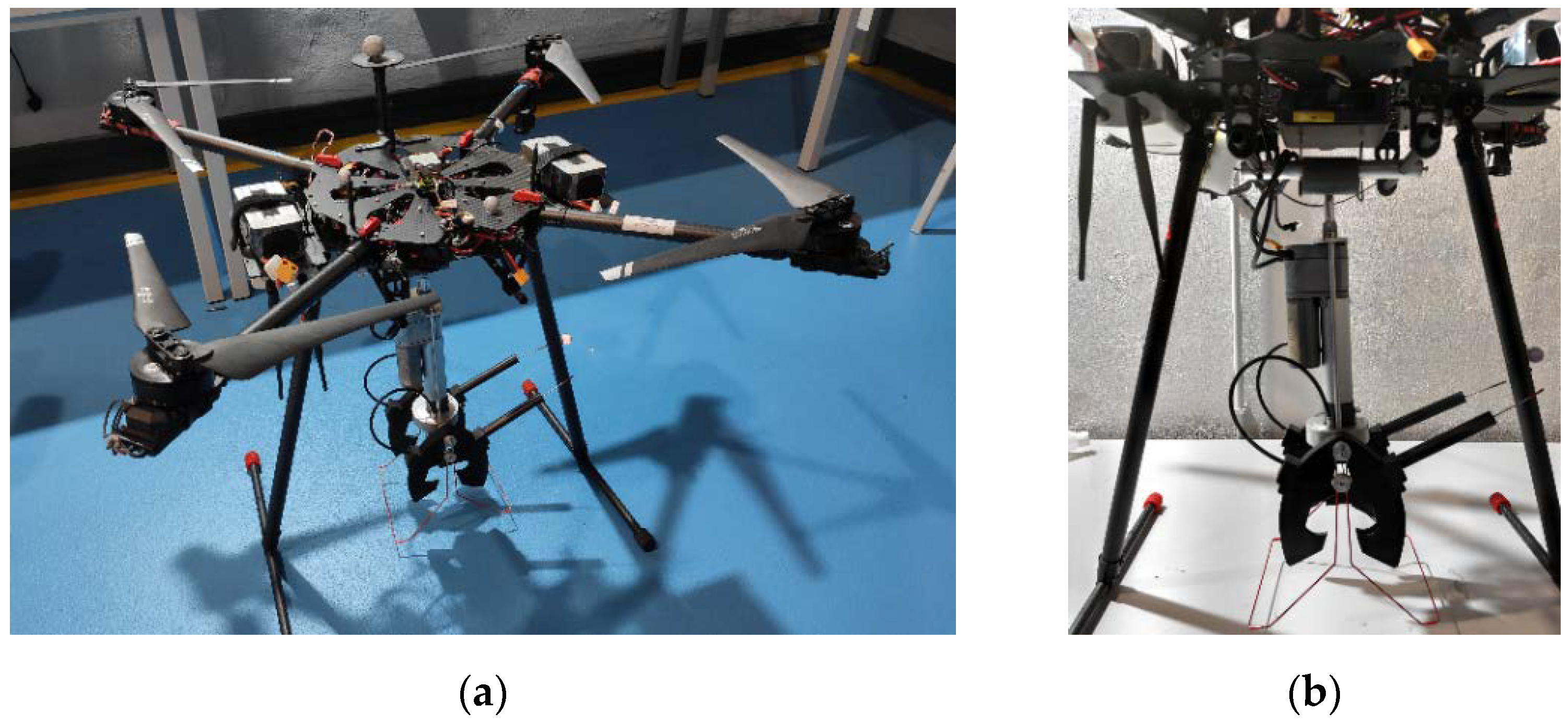
2. Aerial Robot Design and Development

This section describes the design and development of an aerial robot that can install bird clip-type diverters on high voltage power lines. The aerial robot is based on a custom-made multi-copter with a diverter installation tool attached using a pivot joint as shown in Figure 2. The multi-copter flies above the power line and approaches it slowly until the tool touches the cable. Then, it automatically installs the clip-type diverter while the multi-copter is hovering. Once the bird diverter is placed, the aerial platform flies out to the home location. The pivot joint provides some flexibility; it allows some lateral movement of the multi-copter while hovering above the power line during the attachment procedure. The next subsections describe the aerial platform, the diverter installation tool, and the procedure in detail.

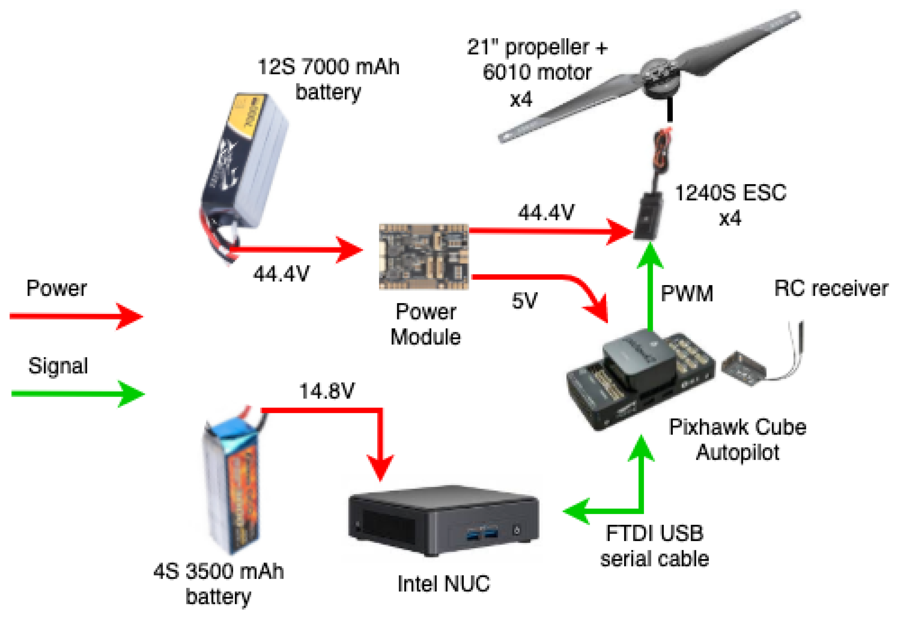
2.1. Aerial Platform

The aerial platform is a custom-made quadrotor (see Figure 2) that weighs 6.5   kg including batteries and avionics. It can carry up to a 3.5   kg payload which is enough for the diverter installation tool ( 1.7   kg ) and one clip-type diverter ( 0.3   kg ). There is a spare payload ( 1.5   kg ) to add more sensors or carry heavier diverters if needed. The distance between its motors is 975   mm , and the height of the quadrotor is 500   mm . The hardware specification is as follows:
Propellers: four ultra-carbon fiber 21 -inch radius propellers are used to generate enough thrust and load capacity in a plus “+” shape configuration.
Motors: brushless direct-current (BLDC) motors, 6010 , with Kv = 130 ( rpm / V ), have been used, where Kv is the motor velocity constant. They provide 5.1   kg maximum pulling force per rotor, with a maximum of 770   W power. It has a cooling air circulation system, convenient for long-term operation. The weight of each motor is 270   g . The suggested battery is 12   S   45   V . Thus, the no-load speed by 12   V batteries is 1560   rpm .
Drivers: a 1240   S electronic speed controller is used as the driver of the BLDC motors. It is waterproof and has silica thermal pads and heat sinks for maximum heat transfer and dissipation. It works with a maximum of 52.2   V and up to 25   A continuous current and 40   A peak.
Main processor: an Intel NUC-i7, with 16 GB RAM, plays the role of the main processor of the UAV. It has USB 3.0, Ethernet, HDMI, Mini PCI Express ports, and low consumption that allows it to work with a 65   W power supply.
− Autopilot: the UAV uses PIXHAWK Cube 2.1 autopilot. It has a 32-bit STM32F427 Cortex-M4F core with FPU, 168 MHz/252 MIPS, 256 KB RAM, 2 MB Flash (fully accessible), 32-bit STM32F103 failsafe co-processor, and 14 PWM/Servo outputs (8 with failsafe and manual override, 6 auxiliaries, high-power compatible).

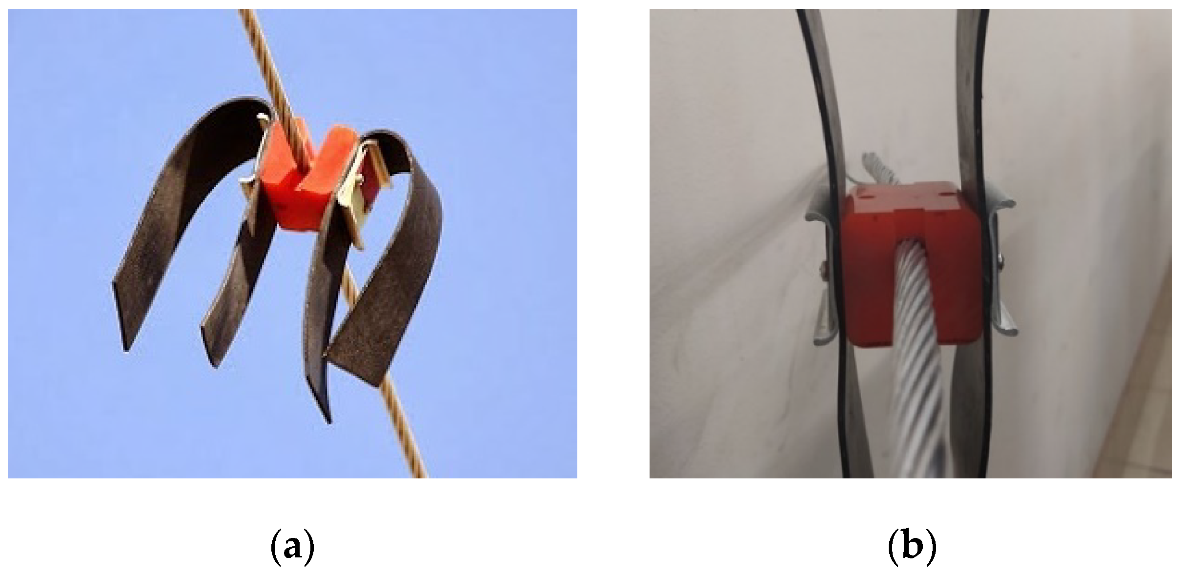
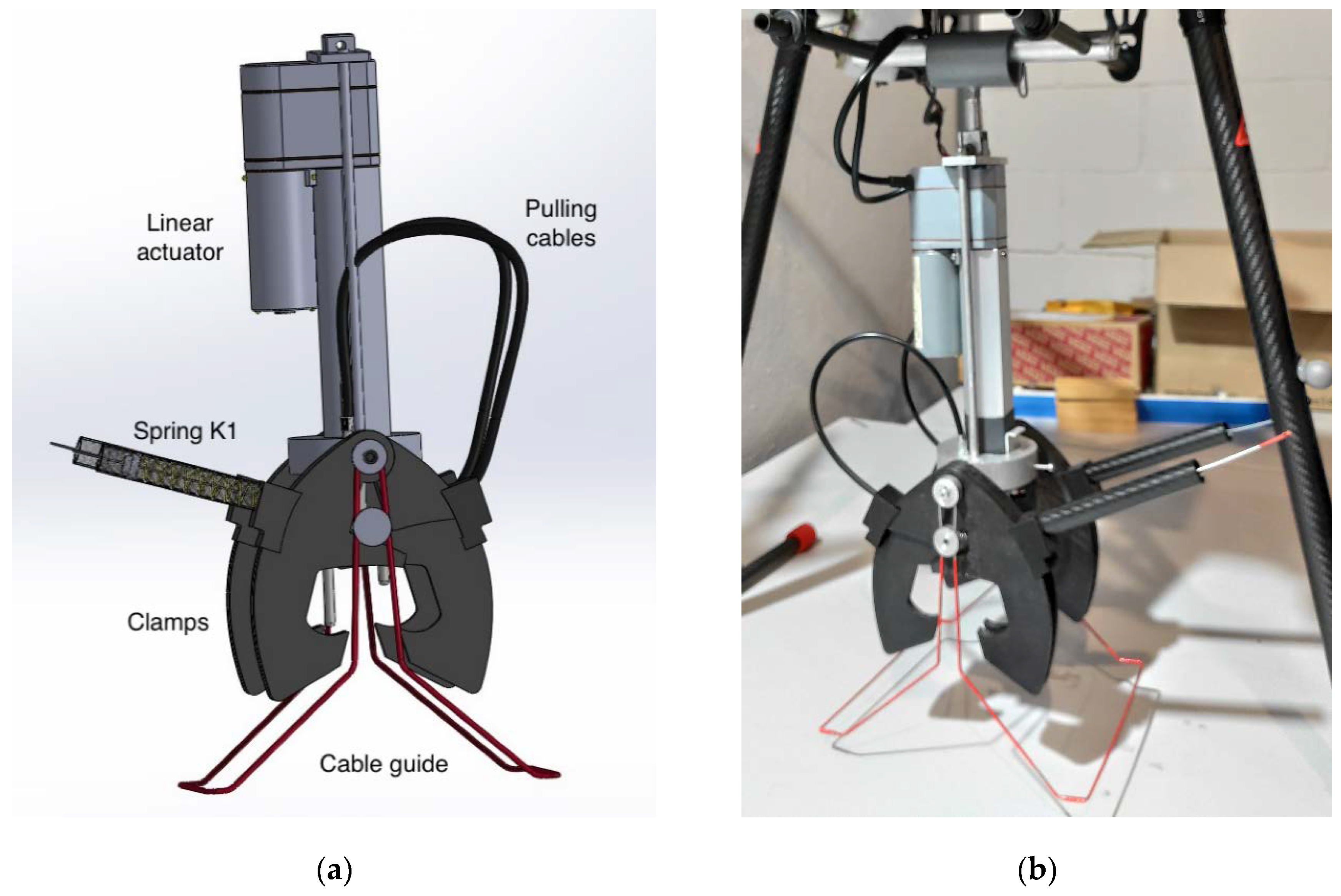
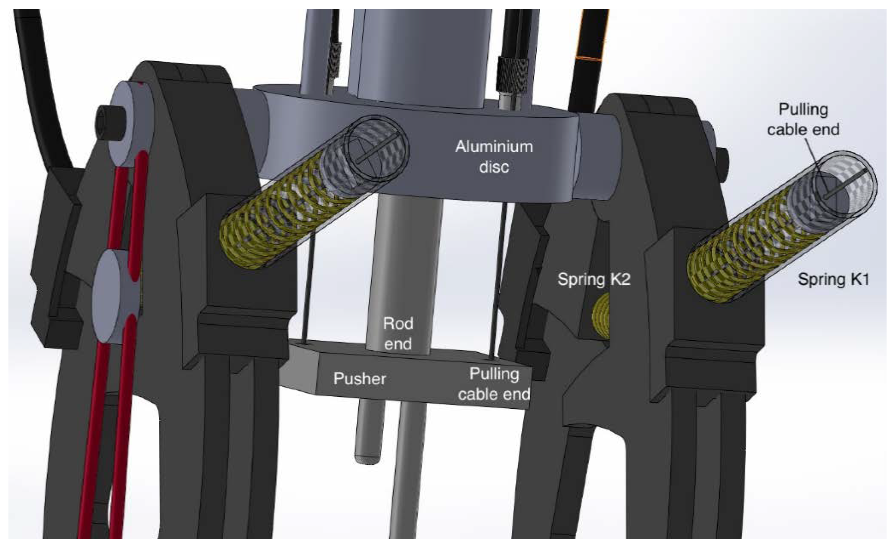
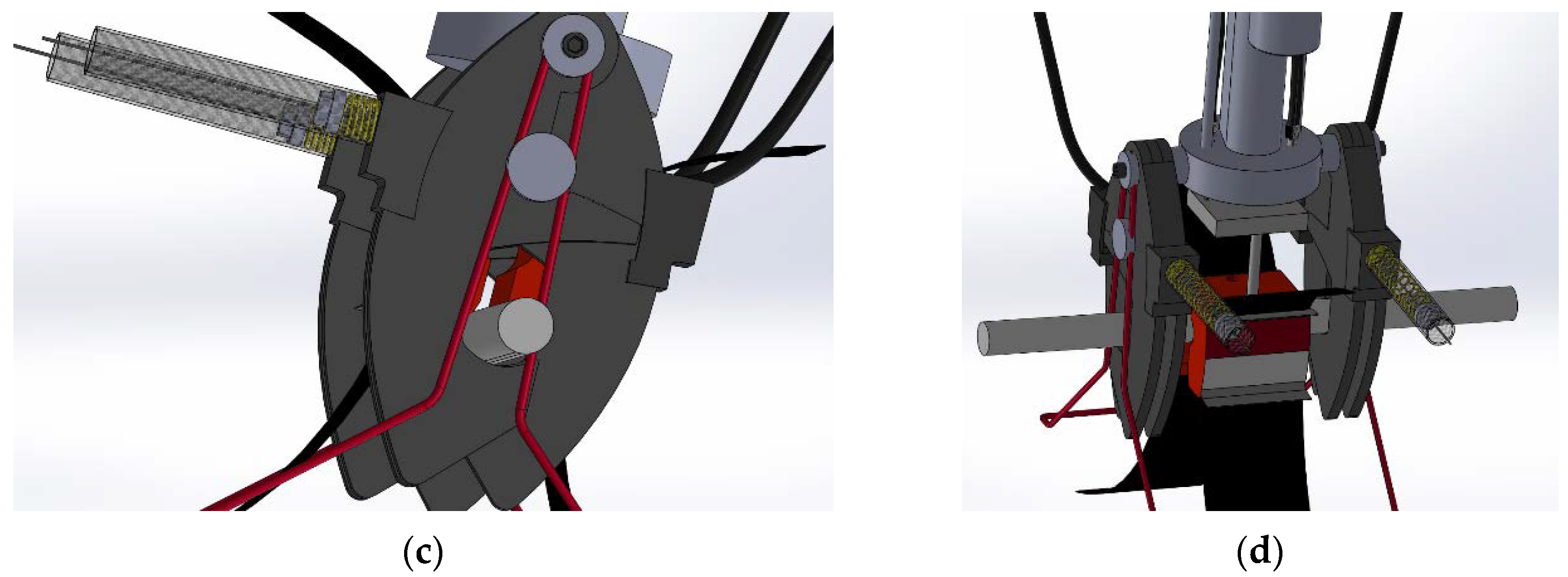
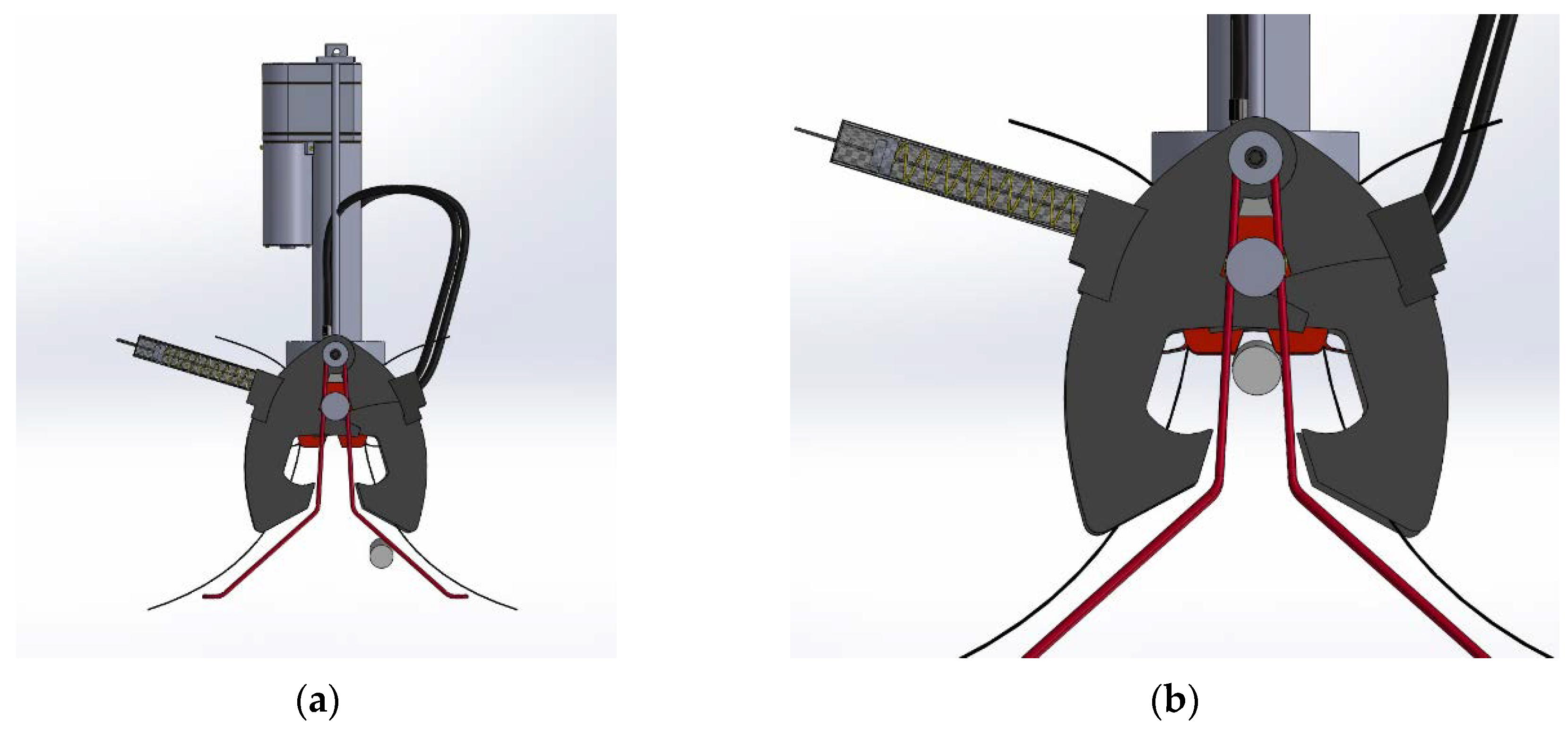
2.2. Diverter Installation Tool

The tool has been designed to meet the following requirements:
  • It should exert at least a 685   N ( 70   kg ) force on the bird diverter: 440   N ( 45   kg ) force to insert the clip plus 245   N ( 25   kg ) force as a safety margin.
  • The force exerted on the UAV during the installation should be minimal.
  • It should be operated easily.
The next subsections describe the mechanical components and how they are mounted, the control electronics, and the insertion procedure.

2.2.1. Tool Design and Mechanical Components

The tool developed has three main components as shown in Figure 3: the electric linear actuator, the clamps, and the pulling cables.
The electric linear actuator is a Firgelli FA-PO-240-12-4. This actuator provides a 200   lb ( 90   kg ) dynamic force with a 4 -inch ( 10   cm ) stroke and a 7.5   mm / s speed. It is equipped with a built-in 10   K Ω potentiometer to provide position feedback, and it is operated using a 12VDC input. The actuator housing is fixed to an aluminum disc that supports the clamps as shown in Figure 3 and Figure 4. The rod end of the linear actuator holds the pusher. This is a square-shaped metallic part with two 6   mm pins that support the diverter and two ends of the pulling cables (see Figure 4).
Two plastic clamps are attached to the aluminum disc as shown in Figure 4. Each clamp is made of two jaws, a pivot joint, an innerspring between the jaws (K2 in Figure 4), and an outer spring (K1 in Figure 3 and Figure 4). The outer spring stiffness (K1) is higher than the innerspring stiffness (K2) by design, and their equilibrium length keeps the clamp open. Moreover, a cable guide (red part in Figure 3) allows for centering the power line cable in the tool and supporting the diverter’s flaps to avoid obstructions during the insertion process.
One pulling cable is needed to close or open each clamp moving the jaws. One end of the cable is attached to the rod end of the linear actuator, then the cable goes through the clamp innerspring K2 (see Figure 4), and the other end is attached to the outer spring K1 (see Figure 3 and Figure 4). When the linear actuator stretches out, the cable is pulled so the clamp closes (compressing both springs). When the linear actuator retracts, the springs recover their equilibrium length, so the clamp opens.

2.2.2. Control Electronics

The control electronics are based on an Arduino Nano board as shown in Figure 5. The control board receives commands from the operator through a radio-control (RC) receiver. Then, the Arduino board regulates the linear actuator stroke with the feedback of the embedded potentiometer. The actuator is commanded through an H-bridge driver, and the whole system is powered using a 12   S LiPo battery, with 7000   mAh at 44.4   V . The details of the voltages and the connections are illustrated in Figure 6.

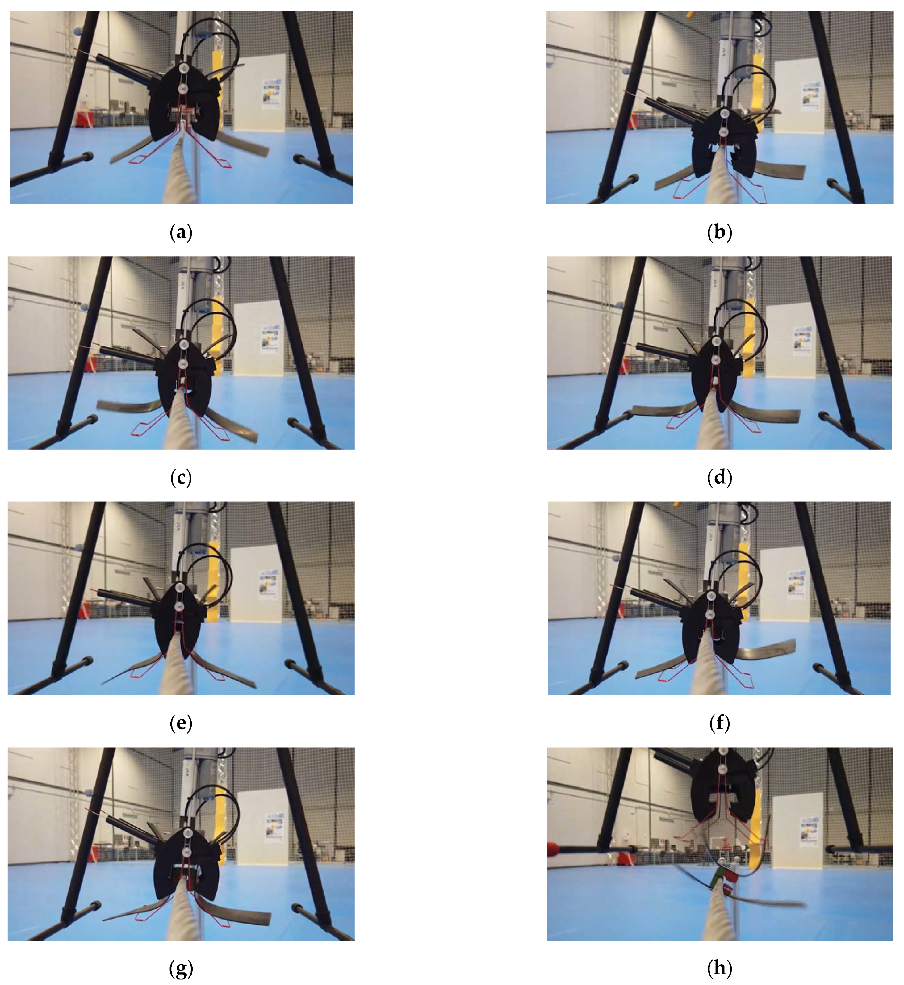
2.2.3. Insertion Procedure

The bird diverter has to be pre-charged in the installation tool before the process starts. For this purpose, the red clip part has to be inserted into the 6   mm pins of the pusher described in Section 2.2.1. Then, the aerial robot is ready to fly towards the power line cable and to approach the installation tool to the cable as shown in Figure 7a. The cable guides (in red) help to center the cable in the tool while the robot is descending (see Figure 7b). The clamps are still open at that moment. When the power line cable is centered in the tool, the insertion process is triggered. The linear actuator stretches out closing the clamps and pushing the clip on the cable as shown in Figure 7c. The force exerted by the linear actuator on the cable is canceled by the clamp’s force, and therefore no force is applied to the aerial robot. In addition, the pivot joint between the installation tool and the aerial robot helps to avoid perturbations that could unbalance the UAV flight. Then the linear actuator retracts, disengaging the clip part (see Figure 7d) and opening the clamps. Finally, the aerial robot can move up and fly back to charge another diverter.

3. Experimental Results
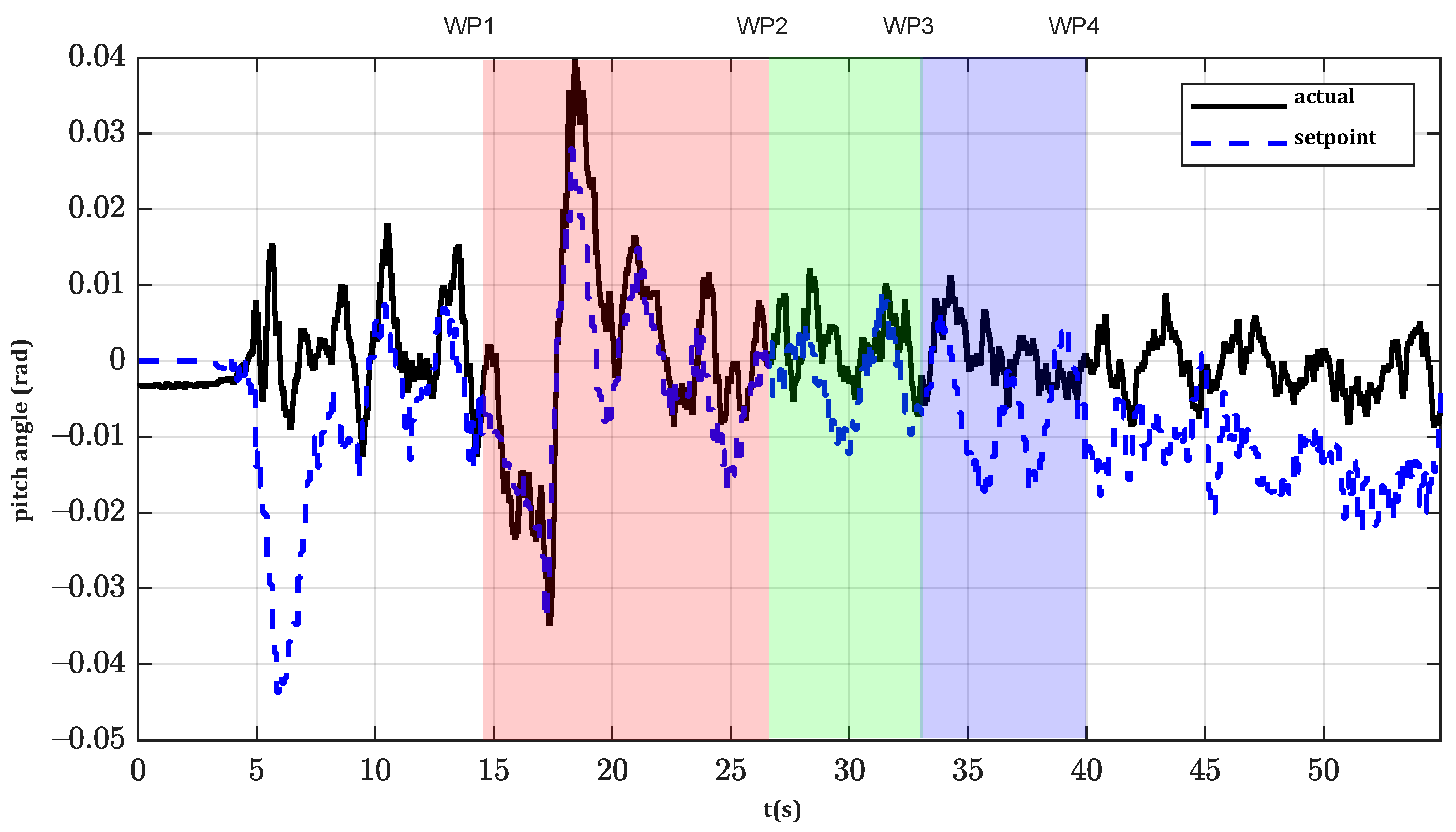
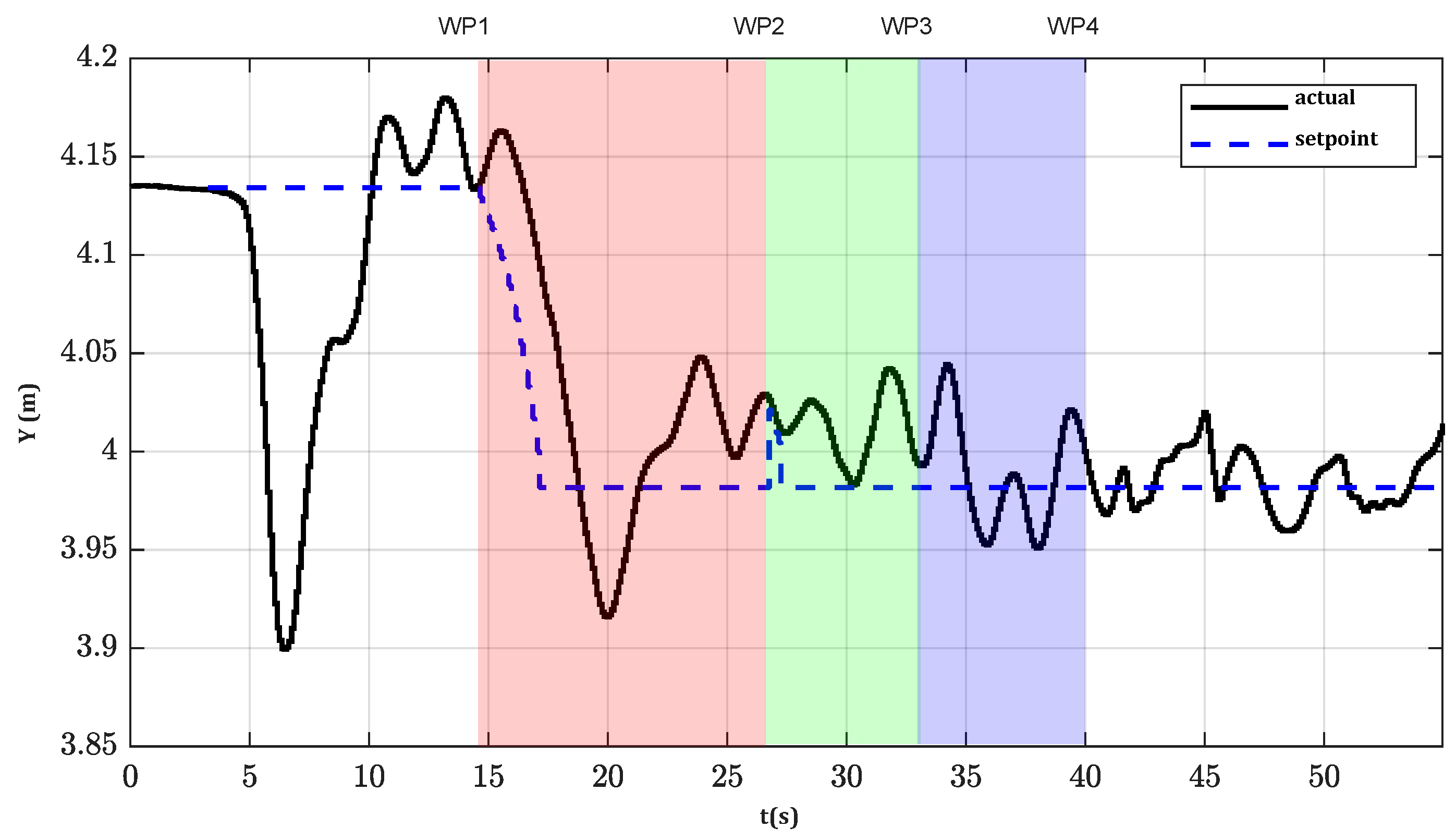
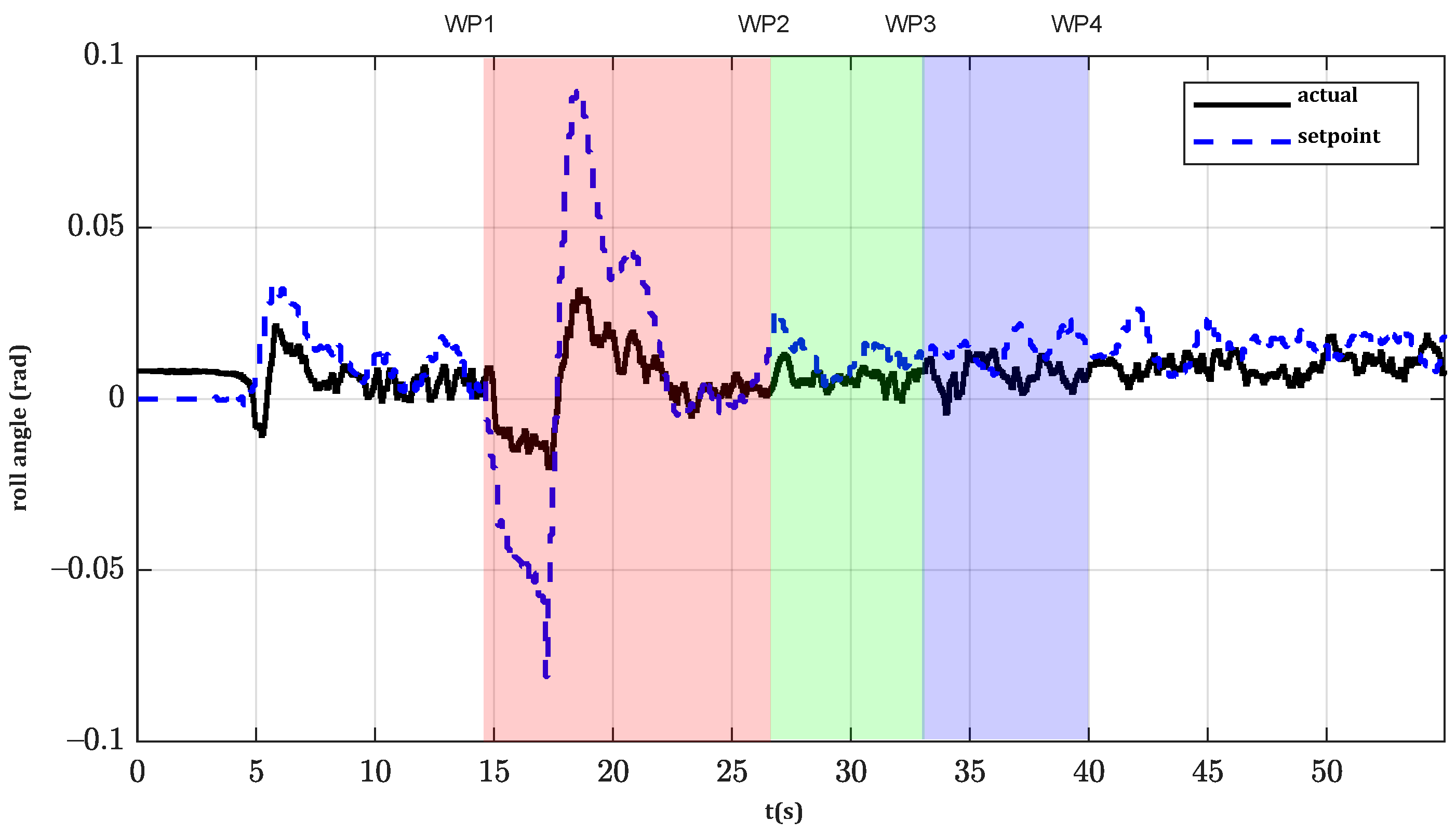
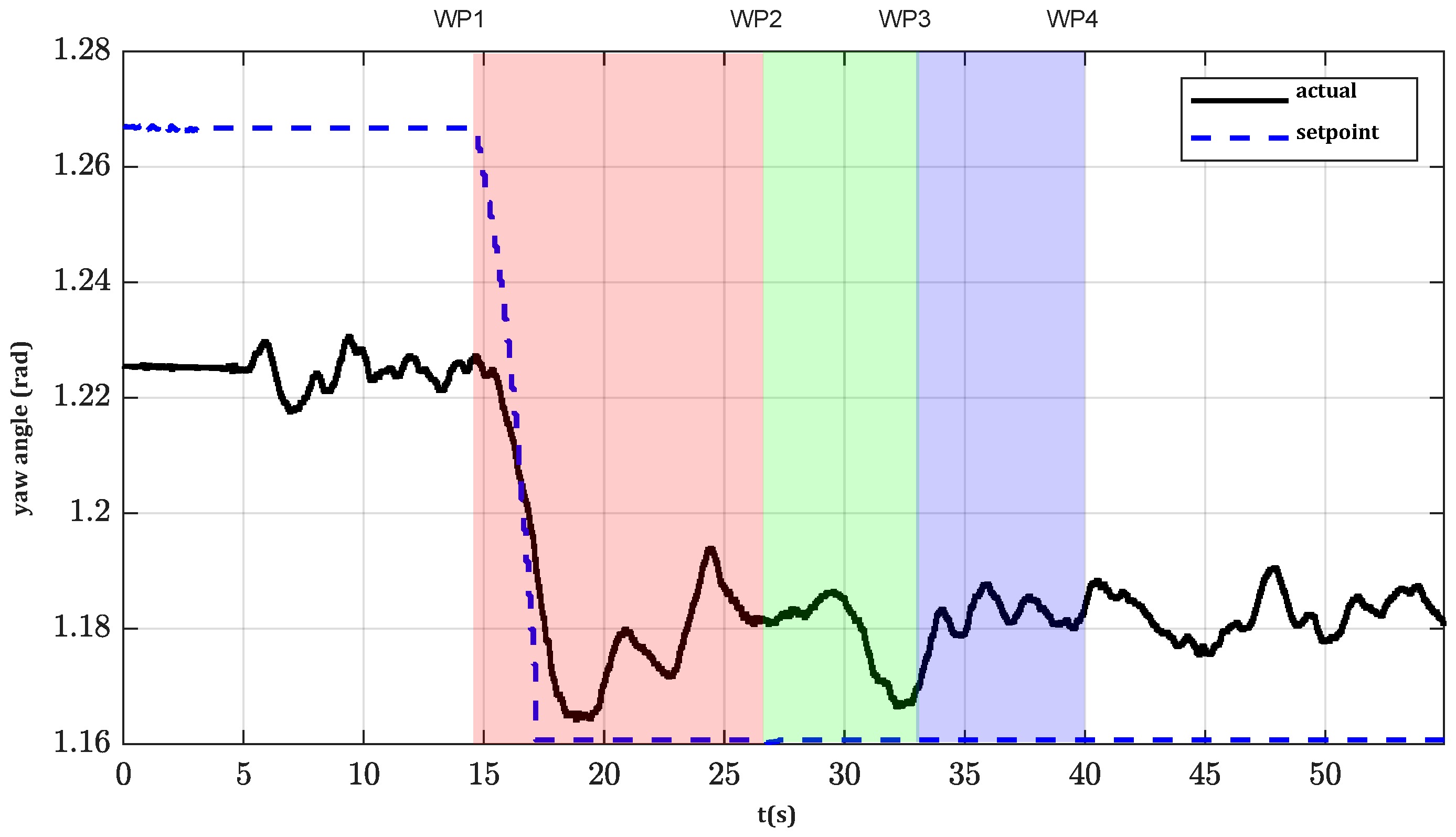
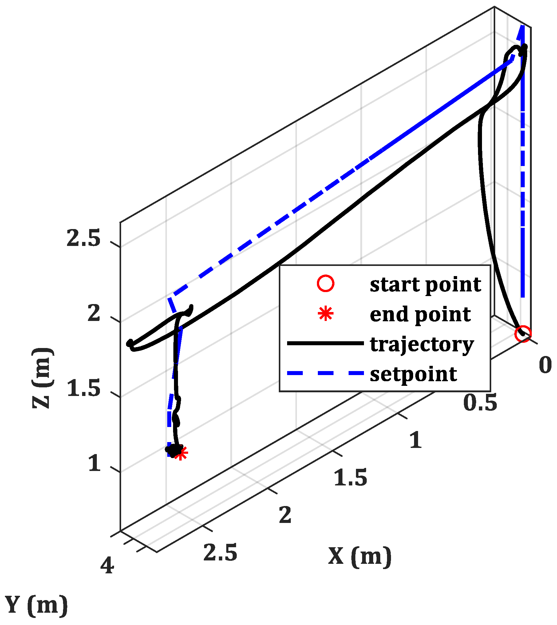
The system has been validated in an indoor testbed using a mock-up as shown in Figure 8. The mock-up is a 2   m long cable suspended at 1   m above the ground. Four positions are defined, namely WP#, and prerecorded using an Opti-Track motion capture system:
WP1 is defined at a 6.5   m distance from the insertion point on the cable and a 2.5   m height.
WP2 is defined above the insertion point at a 2   m height ( 1   m above the cable).
WP3 is defined above the insertion point at a 1.3   m height ( 30   cm above the cable).
WP4 is defined as the insertion point on the cable.
The Opti-Track is an ultra-precise camera tracking system for providing visual feedback to the controller. The current testbed dimension is 20 × 15 × 7   m with high accuracy ( 1   mm ) including 28 cameras. The high data rate translation and orientation feedback are read by the drone’s controller and facilitate the semi-autonomous operation.
The multi-copter autopilot controls the position using the feedback provided by the Opti-Track system. The experiments, shown in the video provided as Supplementary Material, consisted of the following phases:
  • The pilot sends a “Goto WP1” command to the aerial robot, and it takes off to WP1.
  • After reaching WP1, the pilot sends a “Goto WP2” command, so the robot moves toward the cable, and the pilot waits until it is stabilized in that position.
  • Then, the pilot sends consecutive “Goto WP3” and “Goto WP4” commands, and the aerial robot slowly descends to the insertion point (WP4). In this position, the cable is centered in the tool and inside the clamps.
  • After WP4 has been reached, the pilot triggers the installation command, and the diverter installation tool starts its operation, automatically closing the clamps and inserting the clip on the cable.
  • When the pilot visually confirms that the bird diverter has been deployed, he/she sends a fly-up command to the aerial robot, which is finally landed.
The trajectory performed during one of the trials is shown in Figure 9, Figure 10, Figure 11, Figure 12, Figure 13 and Figure 14. The Cartesian coordinates are shown in Figure 9, Figure 10 and Figure 11, and the orientation variables are plotted in Figure 12, Figure 13 and Figure 14. The 3D trajectory of the system is also presented in Figure 15. The oscillations in the y -axis seem bigger than the other x and z axes; however, they are in the same order. Since the motion in the y -axis is almost zero, the oscillation seems bigger than the other two. The UAV takes off and goes to WP1 from t = 0   s to t = 14   s . Then, it navigates to WP2, which is reached at t = 27   s . As shown in Figure 14, during this time slot, the yaw is changed to align the UAV with the cable. The pilot sends the “Goto WP3” command at t = 27   s and the “Goto WP4” command at t = 33   s . The insertion operation is then triggered at t = 37   s . After installing the bird diverter, the UAV flies away at t = 40   s .
The yaw control would need more fine-tuning (Figure 14); however, it was intended to demonstrate that the system works even with misalignment between the tool and the power line. This has been experimentally evaluated; theoretically, the tool design (clamps and cable guide size) and the pivot joint should allow a maximum 8   cm lateral error (if it is perfectly aligned) or a maximum 20   degree misalignment (if the lateral error is zero). The UAV does not try to follow a continuous trajectory, though it tries to reach the predefined waypoints. The UAV reaches each waypoint with an error lower than 4   cm (see Figure 15).
The operation performed during step 4 is illustrated in detail in Figure 16. First, the guide leads the cable inside the clamps (Figure 16a). The insertion operation is triggered when the cable is placed in the middle of the clamps and touching the clip (Figure 16b). The linear actuator stretches out, moving the clamps (Figure 16c) until they are fully closed around the cable (Figure 16d). Then, the actuator continues pushing the bird diverter until the cable is clipped (Figure 16e). Then, the actuator retracts, opening the clamps (Figure 16f); then, the clamp moves back (Figure 16g), and the aerial robot flies up, leaving the bird diverter deployed (Figure 16h).
The effect of the force exerted during the installation on the hovering condition of the UAV is then analyzed. As can be seen in Figure 9, there is only a minor effect on the Z -axis error due to the vertical force during the installation, but the horizontal error (Figure 10 and Figure 11) and orientation angles (pitch, roll, and yaw, Figure 12, Figure 13 and Figure 14) are mainly unaffected.
Three consecutive trials have been performed to validate the repeatability and robustness and to obtain some timing data. The following three-time intervals are measured:
  • Descending toward cable: the time it takes to navigate from WP2 to WP4 and until the pilot triggers the installation procedure. This time can vary because the pilot triggers the operation when he/she considers the UAV is stabilized enough in WP4.
  • Clamping: the time the diverter installation tool takes to insert the bird diverter into the cable.
  • Retreat: the time the linear actuator needs to retreat and open the clamps again, plus the time required to fly back to WP3. This time can also vary because the flyback command is manually triggered by the pilot.
The time details of the experiments are summarized in Table 1. The average time of the operation is 32.6   s (excluding the time required for take-off and navigation from WP1 to WP2). Descending onto the cable takes an average time of 9   s due to the constrained vertical speed and smoothness required. The clamping and retreating stages are automatic and take identical time ( 10   s ), but, as explained before, the decision to fly back is made by the pilot, so “Retreat” values are different in Table 1. It should be noted that the “Descending Toward Cable” phase could take quite a different time in a real operation due to the long flight to cable position.
The flight time was estimated and recorded 20 min of autonomy, measured approximately. Accounting less than 2 min for each diverter ( 30 40   s for installation plus fly back and new diverter uploading), a single battery would install 10 diverters. For real outdoor installation, adding a new device for holding several clips is necessary, which changes the current timing on the indoor tests. The flight to the pylon and back to the station would also be different.

4. Conclusions

This paper describes a prototype that allows for the semi-automated installation of a kind of clip-type bird diverter on power line cables. The current process is usually performed using helicopters, suspended carts, or elevators, this being costly and risky for the personnel involved. Using an autonomous aerial robot would help to reduce risks and increase efficiency. For this purpose, a custom-made novel diverter installation tool has been designed and developed. The novel system presented here is based on a linear actuator and two clamps attached to the aerial robot, and it allows the user to isolate the force exerted on the cable from the aerial platform. To the best of the authors’ knowledge, it is the first semi-autonomous system with a customized design to conduct clip installations on power lines. A set of experiments have been performed on an indoor mock-up scenario, and the system shows a successful performance with acceptable repeatability. The diverters can be installed in less than 40   s , including some delay due to human intervention, and the aerial platform is completely stable during the operation.
Future steps: Future work will include fully autonomous installation using visual servoing to close the control loop and testing in a real de-energized power line cable. In reality, looking up when the UAV is flying near cables is difficult; it is too far away (too high) to see details with the naked eye, it is too fast to see and control with binoculars, the sky is bright and the UAV is dark, and it is very difficult/painful to work with the UAV. The GPS feedback is also not precise enough to provide sufficient accuracy for autonomous installation. As a result, the platform for the real experiment will be different in terms of feedback generation and tracking. It should be noted that the customized add-ons and the insulation, the flight controller, and the quadcopter will keep their design and mechanical structure. For these reasons, the use of onboard cameras and visual servoing is an obligation. Moreover, a new tool for multiple diverter installation is a work in progress. This would allow deploying several diverters without landing to recharge each time, thus increasing efficiency. The final objective is to perform the entire process automatically and efficiently.
The Opti-Track system is unique to indoor experiments. For the real flight and installation, the use of a ground station is necessary where it can localize the UAV for providing feedback. Onboard visual servoing is also proposed for future experimentation for recognition of the cable and giving the pilot/controller visual feedback.
Any wind gust results in bad performance. It is ideal to work in good conditions, though the study could be expanded in the future for adding active disturbance rejection systems or robust controllers.

Supplementary Materials

The following are available online at https://www.mdpi.com/article/10.3390/app11167427/s1, Video S1: The multi-copter autopilot controls the position using the feedback provided by the Opti-Track system.

Author Contributions

Conceptualization, A.R.-C., S.R.N., H.R., R.S. and J.Á.A.; methodology, A.R.-C., S.R.N., H.R., R.S. and J.Á.A.; validation, H.R. and R.S.; formal analysis, A.R.-C. and S.R.N.; investigation, A.R.-C., S.R.N., H.R., R.S. and J.Á.A.; resources, A.R.-C. and A.O.; writing—original draft preparation, S.R.N.; writing—review and editing, A.R.-C., S.R.N. and J.Á.A.; visualization, A.R.-C., S.R.N., H.R., R.S. and J.Á.A.; supervision, A.R.-C. and A.O.; project administration, A.R.-C. and A.O.; funding acquisition, A.R.-C. and A.O. All authors have read and agreed to the published version of the manuscript.

Funding

This work was supported by the European Commission H2020 Programme under the AERIAL COgnitive integrated multi-task Robotic system with Extended operation range and safety (AERIAL-CORE) project, contract number 871479.

Institutional Review Board Statement

Not applicable.

Informed Consent Statement

Not applicable.

Conflicts of Interest

There is no conflict of interest reported by the authors.

References

  1. European-Commission. Guidance on Energy Transmission Infrastructure and EU Nature Legislation; European-Commission: Brussels, Belgium, 2018. [Google Scholar]
  2. Sardaro, R.; Bozzo, F.; Fucilli, V. High-voltage overhead transmission lines and farmland value: Evidences from the real estate market in Apulia, southern Italy. Energy Policy 2018, 119, 449–457. [Google Scholar] [CrossRef]
  3. Red Eléctrica de España. Available online: https://www.ree.es/es/conocenos/principales-indicadores/red-de-transporte-circuito (accessed on 15 December 2020).
  4. Permanent-URL(a). Available online: https://aerial-core.eu/ (accessed on 15 December 2020).
  5. Kim, J.; Ham, Y. Vision-based analysis of utility poles using drones and digital twin modeling in the context of power distribution infrastructure systems. In Proceedings of the Construction Research Congress 2020, Tempe, Arizona, 8–10 March 2020; Computer Applications. pp. 954–963. [Google Scholar]
  6. Bizzarri, F.; Nitti, S.; Malgaroli, G. The use of drones in the maintenance of photovoltaic fields. E3S Web Conf. 2019, 119, 21. [Google Scholar] [CrossRef]
  7. Menéndez, O.; Pérez, M.; Auat Cheein, F. Visual-based positioning of aerial maintenance platforms on overhead transmission lines. Appl. Sci. 2019, 9, 165. [Google Scholar] [CrossRef] [Green Version]
  8. Reddy, A.; Indragandhi, V.; Ravi, L.; Subramaniyaswamy, V. Detection of Cracks and damage in wind turbine blades using artificial intelligence-based image analytics. Measurement 2019, 147, 106823. [Google Scholar] [CrossRef]
  9. Myeong, W.C.; Jung, K.Y.; Jung, S.W.; Jung, Y.H.; Myung, H. Drone-type wall-climbing robot platform for structural health monitoring. In Proceedings of the 6th International Conference on Advances in Experimental Structural Engineering/11th International Workshop on Advanced Smart Materials and Smart Structures Technology, Champaign, IL, USA, 1–2 August 2015. [Google Scholar]
  10. Kocer, B.B.; Tjahjowidodo, T.; Pratama, M.; Seet, G.G.L. Inspection-while-flying: An autonomous contact-based nondestructive test using UAV-tools. Autom. Constr. 2019, 106, 102895. [Google Scholar] [CrossRef]
  11. Ollero, A.; Heredia, G.; Franchi, A.; Antonelli, G.; Kondak, K.; Sanfeliu, A.; Viguria, A.; Martinez-de Dios, J.R.; Pierri, F.; Cortés, J. The aeroarms project: Aerial robots with advanced manipulation capabilities for inspection and maintenance. IEEE Robot. Autom. Mag. 2018, 25, 12–23. [Google Scholar] [CrossRef] [Green Version]
  12. Suarez, A.; Heredia, G.; Ollero, A. Lightweight compliant arm with compliant finger for aerial manipulation and inspection. In Proceedings of the 2016 IEEE/RSJ International Conference on Intelligent Robots and Systems (IROS), Daejeon, Korea, 9–14 October 2016; pp. 4449–4454. [Google Scholar]
  13. Sanchez-Cuevas, P.J.; Gonzalez-Morgado, A.; Cortes, N.; Gayango, D.B.; Jimenez-Cano, A.E.; Ollero, A.; Heredia, G. Fully-actuated aerial manipulator for infrastructure contact inspection: Design, modeling, localization, and control. Sensors 2020, 20, 4708. [Google Scholar] [CrossRef]
  14. Trujillo, M.Á.; Martínez-de Dios, J.R.; Martín, C.; Viguria, A.; Ollero, A. Novel aerial manipulator for accurate and robust industrial NDT contact inspection: A new tool for the oil and gas inspection industry. Sensors 2019, 19, 1305. [Google Scholar] [CrossRef] [PubMed] [Green Version]
  15. Danko, T.W.; Chaney, K.P.; Oh, P.Y. A parallel manipulator for mobile manipulating UAVs. In Proceedings of the 2015 IEEE International Conference on Technologies for Practical Robot Applications (TePRA), Woburn, MA, USA, 11–12 May 2015; pp. 1–6. [Google Scholar]
  16. Larrauri, J.I.; Sorrosal, G.; González, M. Automatic system for overhead power line inspection using an Unmanned Aerial Vehicle—RELIFO project. In Proceedings of the 2013 International Conference on Unmanned Aircraft Systems (ICUAS), Atlanta, GA, USA, 28–31 May 2013; pp. 244–252. [Google Scholar]
  17. Pagnano, A.; Höpf, M.; Teti, R. A roadmap for automated power line inspection. Maintenance and repair. Procedia Cirp 2013, 12, 234–239. [Google Scholar] [CrossRef]
  18. He, T.; Zeng, Y.; Hu, Z. Research of multi-rotor UAVs detailed autonomous inspection technology of transmission lines based on route planning. IEEE Access 2019, 7, 114955–114965. [Google Scholar] [CrossRef]
  19. Teng, G.E.; Zhou, M.; Li, C.R.; Wu, H.H.; Li, W.; Meng, F.R.; Zhou, C.C.; Ma, L. Mini-UAV LiDAR for power line inspection. Int. Arch. Photogramm. Remote Sens. Spat. Inf. Sci. 2017, XLII-2/W7, 297–300. [Google Scholar] [CrossRef] [Green Version]
  20. Zhang, R.; Yang, B.; Xiao, W.; Liang, F.; Liu, Y.; Wang, Z. Automatic extraction of high-voltage power transmission objects from UAV lidar point clouds. Remote Sens. 2019, 11, 2600. [Google Scholar] [CrossRef] [Green Version]
  21. Schofield, O.B.; Lorenzen, K.H.; Ebeid, E. Cloud to cable: A drone framework for autonomous power line inspection. In Proceedings of the 2020 23rd Euromicro Conference on Digital System Design (DSD), Kranj, Slovenia, 26–28 August 2020; pp. 503–509. [Google Scholar]
  22. da Silva, M.F.; Honorio, L.M.; Marcato, A.L.M.; Vidal, V.F.; Santos, M.F. Unmanned aerial vehicle for transmission line inspection using an extended Kalman filter with colored electromagnetic interference. ISA Trans. 2020, 100, 322–333. [Google Scholar] [CrossRef] [PubMed]
  23. Lu, M.; Bagheri, M.; James, A.P.; Phung, T. Wireless charging techniques for UAVs: A review, reconceptualization, and extension. IEEE Access 2018, 6, 29865–29884. [Google Scholar] [CrossRef]
  24. Simic, M.; Bil, C.; Vojisavljevic, V. Investigation in wireless power transmission for UAV charging. Procedia Comput. Sci. 2015, 60, 1846–1855. [Google Scholar] [CrossRef] [Green Version]
  25. Suarez, A.; Salmoral, R.; Zarco-Periñan, P.J.; Ollero, A. Experimental evaluation of aerial manipulation robot in contact with 15 kV power line: Shielded and long reach configurations. IEEE Access 2021, 9, 94573–94585. [Google Scholar] [CrossRef]
  26. Barrientos, R.; Ponce, C.; Palacín, C.; Martín, C.A.; Martín, B.; Alonso, J.C. Wire marking results in a small but significant reduction in avian mortality at power lines: A BACI designed study. PLoS ONE 2012, 7, e32569. [Google Scholar] [CrossRef] [PubMed] [Green Version]
  27. Ferrer, M.; Morandini, V.; Baumbusch, R.; Muriel, R.; De Lucas, M.; Calabuig, C. Efficacy of different types of “bird flight diverter” in reducing bird mortality due to collision with transmission power lines. Glob. Ecol. Conserv. 2020, 23, e01130. [Google Scholar] [CrossRef]
  28. Dwyer, J.F.; Pandey, A.K.; McHale, L.A.; Harness, R.E. Near-ultraviolet light reduced Sandhill Crane collisions with a power line by 98%. Condor 2019, 121, duz008. [Google Scholar] [CrossRef]
  29. Dashnyam, B.; Purevsuren, T.; Amarsaikhan, S.; Bataa, D.; Buuveibaatar, B.; Dutson, G. Malfunction rates of bird flight diverters on powerlines in the Mongolian Gobi. Mong. J. Biol. Sci. 2016, 14, 13–20. [Google Scholar] [CrossRef]
Figure 1. (a) Clip-type bird flight diverter developed by Wigeva currently installed on a power line cable; (b) detailed view of the diverter’s clip part (red) with the cable inserted.
Applsci 11 07427 g001
Figure 2. (a) The aerial platform of the diverter installation process and (b) the attachment of the clip installation tool through a pivot joint.
Applsci 11 07427 g002
Figure 3. (a) Design of the diverter installation tool and (b) the current prototype developed.
Applsci 11 07427 g003
Figure 4. Detailed view of the attachment of the clamps to the linear actuator.
Applsci 11 07427 g004
Figure 5. Block diagram of the control electronics.
Applsci 11 07427 g005
Figure 6. The details of the electronics and voltages of the units.
Applsci 11 07427 g006
Figure 7. (a) Automatic installation process. The aerial robot carries the installation tool with a pre-charged diverter and approaches the power line cable. (b) The cable is centered in the tool while the aerial robot descends. (c) When the cable is in place, the linear actuator closes the clamps and pushes the diverter on the cable. (d) Finally, the linear actuator retracts, detaching the diverter and opening the clamps before flying out.
Applsci 11 07427 g007aApplsci 11 07427 g007b
Figure 8. (a) Experimental setup for validation. The aerial robot takes off to WP1. (b) Then, it stabilizes on WP2, 1   m above the cable. (c) The robot slowly descends to WP3, 30   cm above the insertion point, and (d) it finally reaches WP4, the insertion point.
Applsci 11 07427 g008aApplsci 11 07427 g008b
Figure 9. Z -axis motion during one of the trials.
Applsci 11 07427 g009
Figure 10. X -axis motion during one of the trials.
Applsci 11 07427 g010
Figure 11. Y -axis motion during one of the trials.
Applsci 11 07427 g011
Figure 12. The roll angle of the UAV in clip installation.
Applsci 11 07427 g012
Figure 13. The pitch angle of the UAV in clip installation.
Applsci 11 07427 g013
Figure 14. Yaw angle of the UAV during one of the trials.
Applsci 11 07427 g014
Figure 15. The 3D trajectory of the autonomous clip installation.
Applsci 11 07427 g015
Figure 16. A series of images to show the sequence of the process; (a) approaching, (b) positioning the device, (c) pushing down the diverter, (d) fixing the diverter, (e) clamping, (f) opening, (g) retreating of the linear actuator, (h) fly back to station.
Applsci 11 07427 g016
Table 1. The timing of the clip installation process.
Test Number123Average
Descending toward cable11 s7 s9 s9 s
Clamping10 s10 s10 s10 s
Retreat16 s10 s15 s13.6 s
Total time37 s27 s34 s32.6 s
Publisher’s Note: MDPI stays neutral with regard to jurisdictional claims in published maps and institutional affiliations.

