Abstract
The subject of the present study is the reproduction of a submersible electric pump impeller through reverse engineering and additive manufacturing. All of the phases commonly envisaged in the reproduction of an existing piece were carried out. The aim of the study is to show how the chosen pump component can be effectively re-engineered and produced with the selective laser melting technique, obtaining a final product that is comparable if not even better than the starting one. To achieve this goal, the original piece was redesigned and a new model was created and analyzed. The whole process has been split into three main phases: (i) realization of the three-dimensional model from an existing piece using reverse engineering techniques; (ii) finite element analysis for the optimization of the use of the material; and (iii) 3D printing of a concept model in polyethylene terephthalate by using the fused deposition modeling technology and of the functional model in AISI 316 stainless steel with selective laser melting technology.
1. Introduction
Traditional manufacturing processes involve the realization of components through the succession of two phases: an initial phase of coarse forming (by casting, forging, extrusion, rolling, etc.), followed by a final finishing phase (by cutting, turning, milling, drilling, grinding, etc.). In the first phase, solid parts are created and then modeled through subtractive processes of materials [1]. Alongside these well-established traditional processing technologies, the use of unconventional innovative techniques [2], valid in both phases, has become increasingly widespread. These technologies allow one to carry out processes such as cutting, milling, drilling, etc. through the use of innovative processes including lasers [3], plasma [4], water jets [5], and electro-erosion [6].
The push towards the research and industrialization of innovative, unconventional processing technologies is linked to the most important disadvantages of traditional ones [7]. In fact, although the vast majority of objects are still today made using traditional techniques, production based on material removal processes requires auxiliary support systems (such as electricity, water, air compressed, steam, waste water, purification), often large workspaces, and conspicuous natural and energy resources [8]. Production is centralized, taking place in large industrial systems with huge storage warehouses downstream, from which the finished product is distributed to the customer. Traditional manufacturing, therefore, proves to be little oriented towards environmental, energy, and economic sustainability, leading to the need to research and optimize innovative and more sustainable production processes [9].
In this context, the role of 3D printing or additive manufacturing (AM) processes, born and developed initially to meet the needs of rapid prototyping, is crucial [10]. These processes involve the manufacture of artifacts by overlapping multiple layers of material, starting from a 3D model of the object to be created. The layers are compacted by melting the material, which then solidifies into the desired geometry [11]. The starting 3D model can be either the result of a CAD design or a 3D scan of a real object. The software that governs the 3D printers, divides the digital model of the object into superimposed layers (slicing), and then controls the deposition of the material. Additive manufacturing processes allow one to work with different materials such as plastic polymers [12], metals [13], ceramics [14], and composites [15]. Technological evolution has led to the possibility of using materials with industrial characteristics capable of withstanding high temperatures and significant mechanical stress [16]. Today, the use of 3D printing proves to be an optimal technology for small series productions or where great flexibility and a high level of customization of the finished product are needed [17].
Compared to traditional subtractive manufacturing, additive manufacturing technology offers several advantages such as the possibility of creating, in a single piece, shapes with complex geometries, avoiding traditional assemblies [18]; the reduction of processing waste; the possibility of using alternative and innovative materials [19]; the reduction of production costs associated with the fabrication of objects in small series; great ease of customization of an object [20] compared to a basic model, with very low costs to manage production variations, and not requiring intervention on the machine equipment; the significant reduction of the “time to market”, thanks to the possibility of producing small batches to be placed on the market, for an initial evaluation of the product response, and only then activating a large-scale production; and the possibility of producing components “on-site”, thus also reducing warehouse stocks [21].
However, the spread of 3D printing in mass production is still limited by several factors, the most significant of which is low productivity, linked to the current limited 3D printing speeds [22]. If this aspect is negligible in prototyping, certainly it is not so for large-scale production. Instead, at the quality level of the finished object, due to the overlapping of layers typical of AM processes, it is possible that the presence of “hidden” defects between one layer and another, which are more difficult to verify than for a solid object, are first cast and then finished as in classical production [23,24].
Nowadays, additive manufacturing systems are based on different technologies. For example, fused deposition modeling (FDM) uses thermoplastic materials (such as PLA, ABS, nylon, PET, ultem, polycarbonates) melted at high temperatures through an extruder and then deposited on a printing plate, creating objects of complex geometry with an accurate level of precision [25]. The selective laser sintering (SLS) process instead uses a laser beam to selectively sinter portions of a powder bed within a compact layer. This technique allows the use not only of plastic material but also of ceramic, glass, and metal powders [26]. Once a cross-section of powder is sintered, the printing platform is lowered to allow the deposition of a subsequent layer of powder. The process is repeated until the production of the model is complete. The selective laser melting (SLM) technique instead allows the use of different materials (such as aluminum alloys, titanium, chromium, cobalt, steel, and nickel) fused from a bed of powder through a high power laser, obtaining prototypes and components such as inserts for injection molds [27]. The products have excellent mechanical characteristics and a high finishing degree, such as to be used also in the goldsmith sector and in the production of medical prostheses. Finally, the multi jet fusion (MJF) process, developed by Hewlett–Packard (HP), represents the last evolution of AM technologies. It is based on the use of multiple material jet nozzles, which deposit a fusion agent to selectively melt the particles [28]. This technology allows one to produce very thin successive layers and to obtain a finished object with a high density, low porosity, and a very high level of aesthetic finish. The presence of more nozzles also allows a significant increase in productivity, compared to other 3D printing systems [29].
Currently, the application of AM processes is still an unexplored area in many industrial sectors, including that of the production of impellers for electric pumps, proposed in this study, in which its modeling is analyzed using reverse engineering techniques [30]. This operating machine is composed of an electric motor, generally asynchronous, connected through a joint to a pump (axial, centrifugal, or radial). Its task is to transform electrical energy into potential energy, available in the form of pressure in the liquid. Most of the impellers on the market are made using precision casting processes, but it is estimated that in the coming years there will be an increasing use of additive manufacturing, similar to what happened to the production of components for the aerospace industry (subsidized by heavy investments in major airlines companies) [31].
The integration of reverse engineering (RE) techniques to AM processes has been already successfully studied in many sectors, such as the industrial sector, and is involved in the maintenance or replacement of machine elements, such as turbine blades [32], and the development of specific surgical implants for patients [33], until the application in the production of small-scale cultural artifacts [34].
The integration of additive manufacturing technology into the high-performance stainless steel submersible pump market would allow the development of impeller blade profiles with a greater hydraulic efficiency [35], thanks to a greater design freedom, with the possibility of easily creating complex shapes and using ultra-light and ultra-resistant materials, such as titanium or aluminum alloys, to reduce masses, thicknesses, and wear. Further advantages relate to the possibility of customizing the hydraulic characteristics of the pump body so as to maximize internal efficiency, for all applications, with a significant improvement in energy conversion processes [36].
To date, few literature papers have verified the possibility of integrating RE techniques with AM for the development of high efficiency pumps. Rajenthirakumar and Jagadeesh [37] used CAD systems, supported by a computational fluid dynamics (CFD) analysis, for rapid optimization of impellers’ parameters. The integration of RE and CFD techniques has also been successfully studied by Chen et al. [38], for the manufacture of SLS prototypes of blood pump impellers which are dimensionally accurate, structurally robust, and inexpensive. This combination has also been proposed by Quail et al. [39], in the development of an impeller with complex blade profiles, using the FDM technique, verifying how it could represent an excellent alternative to conventional numerical control milling processes which are difficult and expensive for complex geometries. The application of RE techniques for the design of high efficiency impellers, manufactured using SLM, was successfully verified by Jia et al. [40] who fabricated a TiAl6V4 lattice structure, to reduce the mass and the moment of inertia, verifying an increase in mechanical and structural performance. Elizondo and Reinert [41] reproduced the spare part of an aircraft’s wing holder, made of Inconel 718 alloy, in order to ensure a more efficient, simpler and lightweight design. Adiaconitei et al. [42] studied the development of an impeller, made by the SLM technique and subsequent abrasive flow machining, evaluating its performance in terms of manufacturing time and geometric accuracy compared to conventional methods. Finally, Huber et al. [43] studied the optimal orientation of build direction and the design of support structures for small impellers made of the Inconel 625 alloy.
In this context, the present work deals with the proposal of a reverse engineering approach aimed at reproducing an impeller for a submersible electric pump. First, the reconstruction of the 3D model of the impeller is made by traditional measuring systems and a topographical optimization is proposed in order to simplify the geometry of the impeller while ensuring the same performance or even improving it. Therefore, this optimized model is used to analyze the mechanical performance in terms of stress deformation through a finite element method-based simulation. Then, the fused deposition modelling and the selective laser melting processes have been used to realize the concept and the functional models, respectively. Finally, the functional model has been inspected to evaluate the geometric accuracy with which it is reproduced, and to define if the SLM technique could be considered suitable for the fabrication of highly-customized and efficient impellers for submersible electric pumps.
2. Materials and Methods
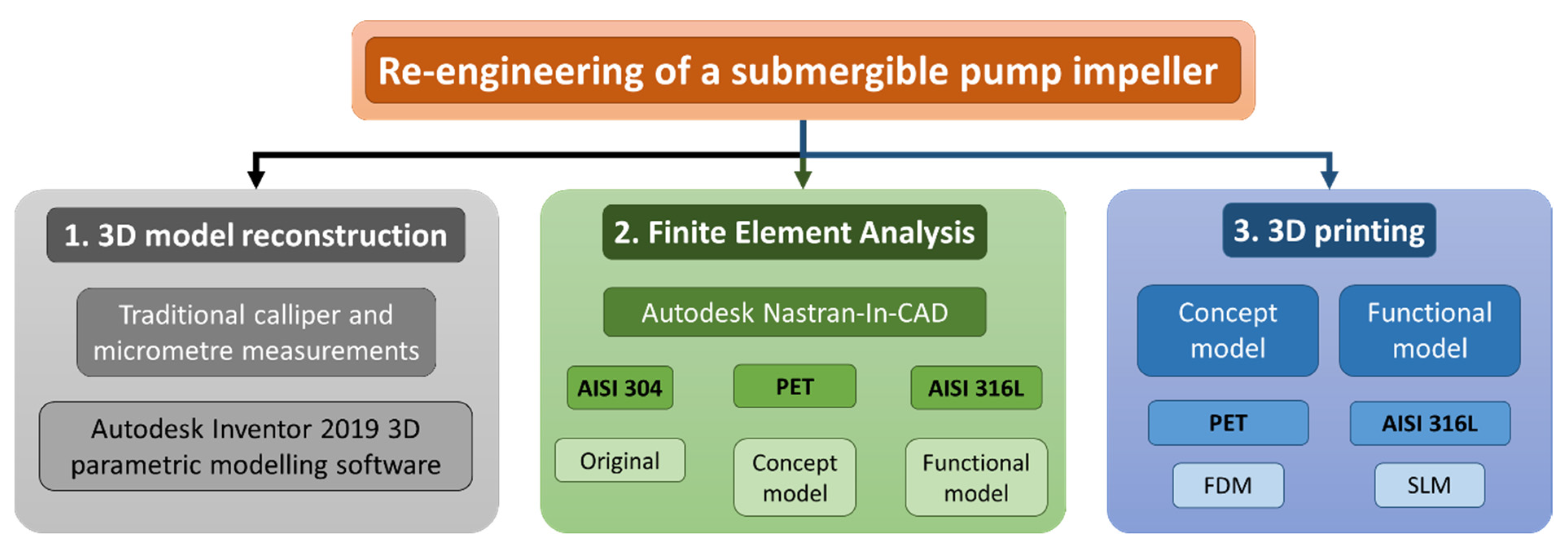
The aim of the present study is to show how the chosen pump component can be effectively re-engineered and produced with the SLM technique, obtaining a final product that is comparable if not even better than the starting product. To this end, the investigation concerned three main activities, as shown in Figure 1 and detailed in the next sections. The following is a short summary:
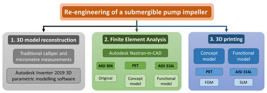
Figure 1.
Flowchart of the activities carried out for the re-engineering of the impeller of a submersible electric pump.
- The first activity concerned the reproduction of a 3D model of the chosen submersible electric pump impeller using reverse engineering techniques and creating the model within the Autodesk Inventor environment;
- The second step was aimed at evaluating the mechanical response of the proposed materials and models to be printed with additive manufacturing techniques by means of a finite element analysis through the Autodesk Nastran-IN-CAD environment; this phase allowed predicting the applicability of the 3D printed functional model;
- Finally, both the concept and the functional prototypes were printed by using the fused deposition modelling and the selective laser melting techniques, respectively. In particular, the concept prototype is used to assess the feasibility of the re-engineered impeller model and to make the designer able to carry out the appropriate changes before the final printing of the functional model in SLM, which should be used for the final application.
2.1. 3D Impeller Model Reconstruction
The first step of this study was the reproduction of the three-dimensional model of a submersible electric pump impeller using reverse engineering techniques.
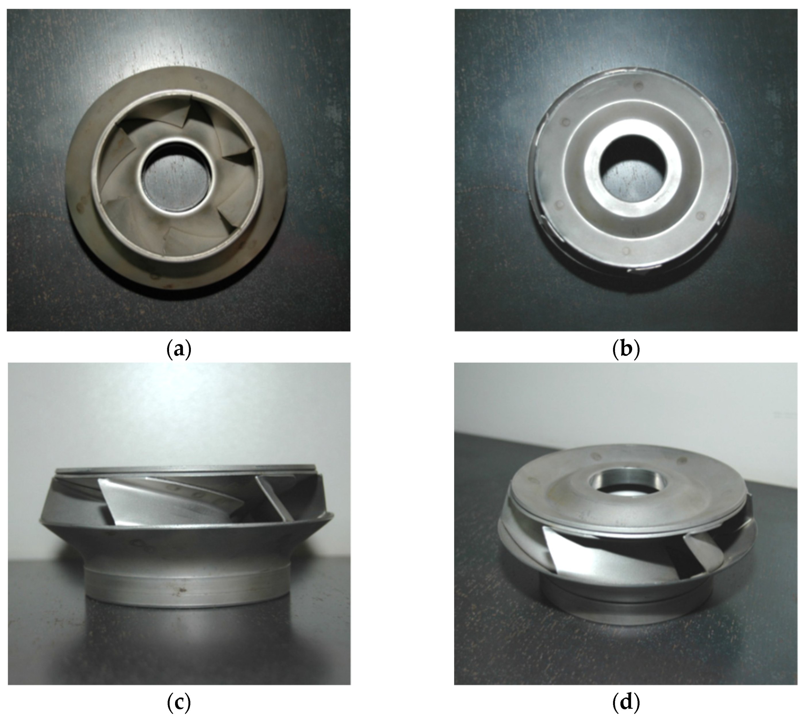
The existing impeller, chosen for the present work, is the one supplied with the SP 215 pump produced by the Danish company Grundfos. It is made of AISI 304 stainless steel sheets that are bended and spot welded, while the majority of the impellers of the competitors are made using precision casting processes (see Figure 2). The Grundfos pumps of the SP 215 series have very high hydraulic efficiency and, thanks to the used materials, high resistance to corrosion due to pumping aggressive fluids.
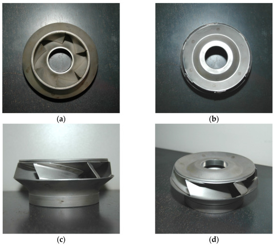
Figure 2.
Impeller of the SP 215 pump produced by Grundfos: (a) top view; (b) bottom view; (c) side view; and (d) 3D view.
Nowadays, there are several technologies to support the reverse engineering process including: (i) 3D laser scanner, with which it is possible to obtain, through laser scanning, a basic three-dimensional model of the piece to be subsequently perfected with parametric modelling software; (ii) digitizer probes with a measuring arm, with which it is possible to obtain the coordinates, in a virtual reference space, of the points of the surface of the piece being measured, by converting the angular values, detected by encoders, of the arm joints when the surface comes into contact with the feeler; and (iii) traditional measuring instruments and techniques (e.g., caliper, micrometer, traditional projection of the profiles on the plane, identification of the coordinates of the nodes of the curves, detection of the main dimensions in direct and indirect mode using a gauge).
In this study, in order to define the sketch of the digital model of the impeller, the main dimensions of the real piece were obtained mainly through the traditional approach due to its simplicity and cost-effectiveness (see Table 1 and Table 2 and Figure 3).

Table 1.
Main dimensions of the impeller of the SP 215 pump measured by adopting the traditional measuring instruments (i.e., caliper and micrometer). For the visualization of the dimensions refer to Figure 3.
Table 2.
Thickness values of the sections constituting the original impeller by Grundfos measured on three random points (indicated as #1, #2, and #3 for sake of simpleness). All of the values are expressed in mm. “Std” stands for standard deviation.
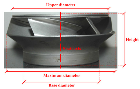
Figure 3.
Main dimensions of the impeller of the SP 215 pump.
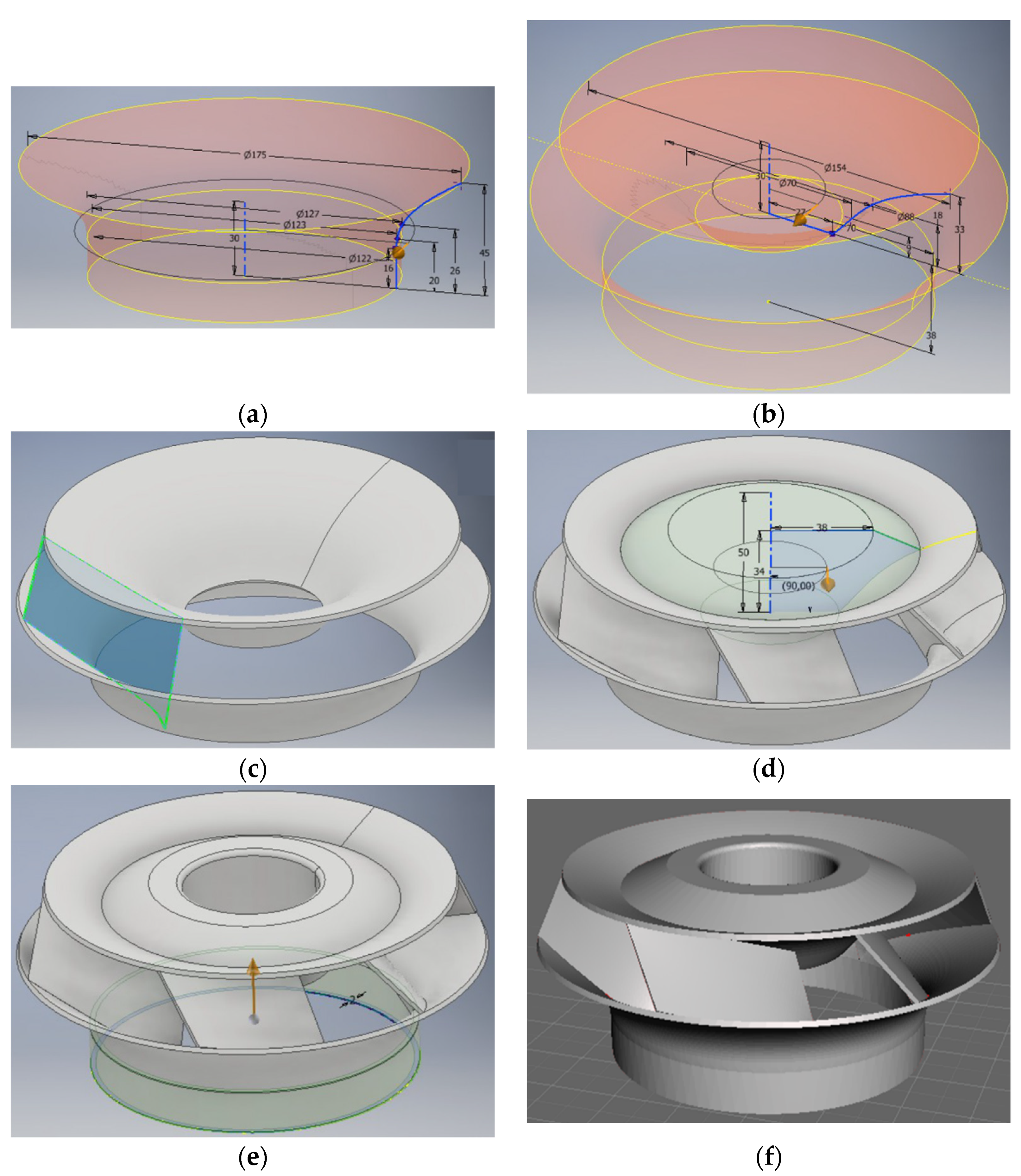
The digital model of the electric pump impeller was created using the Autodesk Inventor 2019 (by Autodesk, San Rafael, CA, USA) three-dimensional parametric modelling software (see Figure 4). The modelling process was carried out in several steps, the main ones of which are reported in the following:

Figure 4.
Modelling process of the impeller: (a) surface of revolution from the 2D sketch of the lower flared part; (b) surface revolution of the upper flared part; (c) thickening of the walls and definition of the geometry of a blade; (d) reproduction of the blades around the profile of the impeller; (e) creation of the central hole and of the wear ring at the base of the impeller; and (f) resulting 3D model. All the dimensions are expressed in mm.
- Modelling of the lower flared part;
- Modelling of the upper flared part;
- Impeller blade modelling;
- Circular series of the impeller blade to obtain the other five blades;
- Modelling of the reinforcement solid for connection to the axis;
- Modelling of the lower wear ring.
First of all, a sketch was created starting from the taken measurements and from side photos of the piece to trace its profile. In this phase, it was possible to make some simplifications compared to the original model made of press-bent and spot-welded sheet metal. In fact, the different traditional phases of production of the piece require specific thicknesses and angles of modeling of the sheets that are not necessary with the additive manufacturing technique. It is worth reporting that a total filling of the upper flared part has been carried out (see Figure 5a,b). This is the part through which the impeller is coupled to the pump shaft. The total filling was done to ensure greater resistance to the upper flared part and therefore the success of the SLM printing process. Specifically, the thickness of the upper flared part was kept the same of the original impeller at 1.90 mm in average (see Table 2). The same value was chosen also for the lower flared part in order to guarantee the continuity of the thickness for the 3D printing process, against the original value of around 1.82 mm in average, as reported in Table 2. Moreover, for the realization of the profile of the blades, in order to inspect the edges and how they are connected with the flared parts, it was necessary to dissect a faulty impeller, since some sections of the edges were not accessible. In particular, the simplification of the blades concerned considering them directly connected to the flared parts without the need of extra bended flaps for the welding, as shown in Figure 5c,d. In addition, the thickness of the blades was reduced from 1.60 mm (i.e., the average of all the measurements made on the blades and listed in Table 2) to 1.30 mm. Such a value was chosen according to the following FEA analyses (Section 2.2) as the optimal one ensuring a similar response if compared with the original impeller.
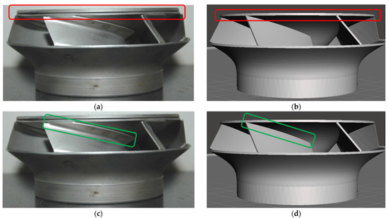
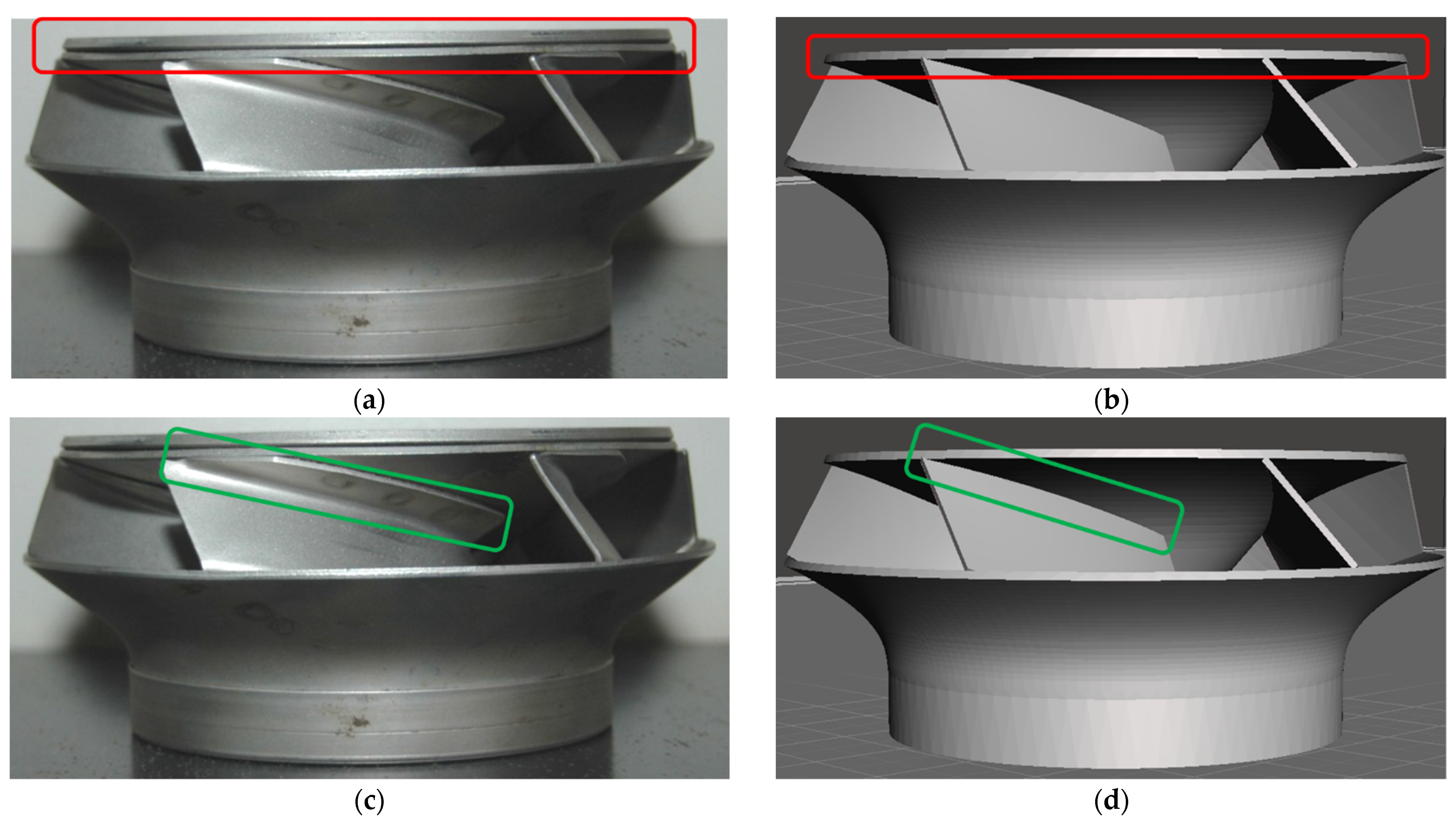
Figure 5.
Topographic optimization and modification of the flared parts and blades for improving the resistance of the impeller and guarantee the success of the SLM printing process: (a,b) complete filling of the upper flared part; (c,d) simplification of the blade hanging by removing the bended flap.
2.2. Finite Element Analysis
The model (see Figure 4) reproduced by following the approach presented in Section 2.1 has been used for the FEM simulations and the next 3D printing of both the concept and the functional impellers. In particular, the study of the stresses and deformations of the materials was carried out through the finite element analysis (FEA) Autodesk Nastran-In-CAD 2019 software, within the Autodesk Inventor 2019 environment. In particular, three different configurations of materials and techniques for making the impeller were studied (see Table 3 for the details):
Table 3.
Main properties of the adopted materials for the finite element analysis. The values reported for the AISI 304 and PET are those suggested by the Autodesk Inventor 2019 software, while for the AISI 316L the typical average values evaluated after the SLM printing process [44] have been accordingly added.
- AISI 304 stainless steel sheet work-hardened by plastic deformation through molding;
- PET for the 3D printing of the concept model through fused deposition modelling (FDM);
- AISI 316L stainless steel for the 3D printing of the functional model through selective laser melting (SLM).
The first adopted configuration considers the original material of the Grundfos impeller (i.e., AISI 304 stainless steel), while for the 3D printing technique SLM is the AISI 316L stainless steel. The choice of the AISI 316L stainless steel comes from the availability of the material as a metal powder for the SLM technology and due to the fact that the presence of molybdenum as an alloying element, which is absent in the grade 304, is more suitable for corrosive and humid environments.
For both metal materials (i.e., AISI 304 and AISI 316L), a linear analysis under the hypothesis of small displacements was carried out. Conversely, since the polymeric material is subject to non-linear deformation, a non-linear analysis was performed for the PET. The analysis was limited to an impeller blade as the most stressed part.
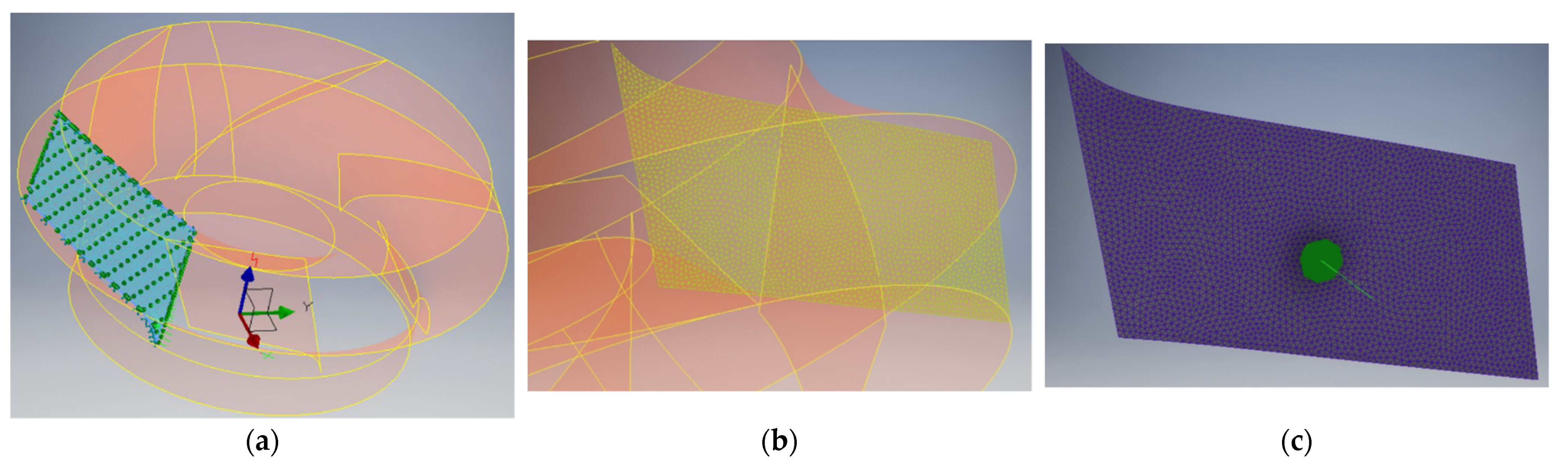
A shell-type idealization was chosen since, the thickness of the component being much smaller than the other two dimensions, it fairly faithfully represents the behavior of the solid model. The mesh was set with a characteristic size of 1 mm of the triangular element of the grid. Such a dimension was chosen according to that one able to reduce the solution error to values lower than 10−13. Constraints were imposed, and placed on the upper and lower edges of the impeller blade, as shown in Figure 6a,b.

Figure 6.
FEA analysis configurations for the stresses and deformations evaluation on a single blade of the impeller: (a) shell-type idealization, (b) meshing with a characteristic size of 1 mm of the triangular element of the grid, and (c) pressure load application.
A pressure load of 3 MPa on the external blade surface was assumed, represented in Figure 6c with the green arrow. This value corresponds to the pressure produced by the maximum water column that lifts the electric pump equipped with this type of impeller. In other words, the force of pressure is distributed in accordance with the highest prevalence of exercise of the pump model analyzed.
Once the constraints were fixed, the pressure load on the external face of the blade was set. Then the resolution by Nastran was initiated to obtain the Von Mises stress diagram and the deformation of the surface.
2.3. 3D Printing
For the concept model printing, the FDM (fused deposition modelling) method was adopted, due to the speed of implementation and the low cost. An AnyCubic—Predator Delta printer (by Anycubic, Shenzhen, China) was used for printing, whose main features are reported in Table 4. The used material is PET, a thermoplastic polymer belonging to the family of polyesters and suitable for food contact. PET is extremely resistant to the action of chemicals and it is ideal for obtaining waterproof models. Basically, no odor is produced during printing. Shrinkages are particularly limited and, consequently, the tendency to develop deformations is minimal. The adopted printing parameters are listed in Table 5.
Table 4.
Main features of the AnyCubic—Predator Delta FDM-based 3D printer used for the realization of the concept model made of PET.
Table 5.
Printing parameters set in Slic3r software for the realization of the concept model made of PET with the 3D FDM-based printer AnyCubic—Predator Delta.
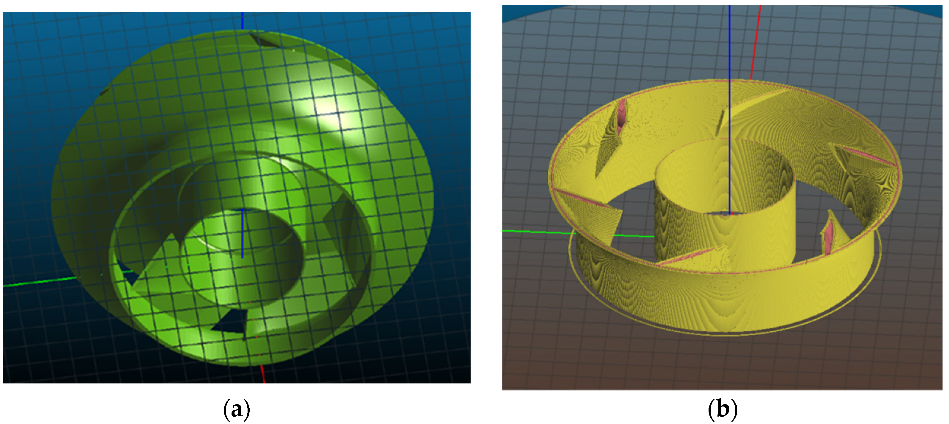
In order to simplify the printing process and avoid the use of support material, which is difficult to remove when using PET, a support tube has been added to the model which, resting on the base, supports the upper flared part of the impeller (see Figure 7). The open-source software Slic3r was used to slice the model for the creation of the machine code (.gcode) to be sent to the printer in FDM technology.

Figure 7.
Support tube added to the upper flared part of the impeller in order to avoid using the support material suggested by the slicing software: (a) bottom view and (b) internal view.
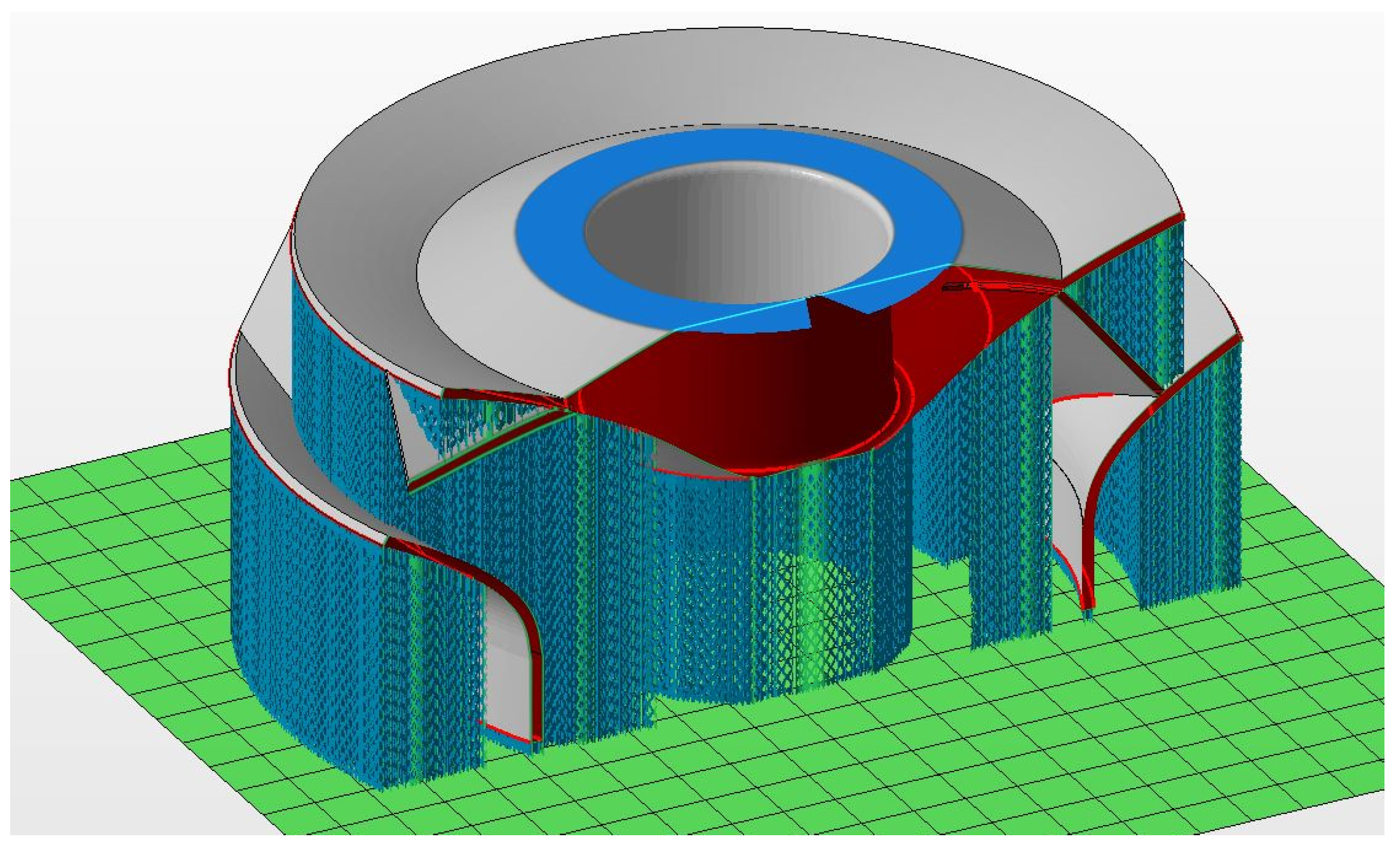
The functional model was then printed through a 3D printing service (ZARE S.r.l.), a leader in the market and operating for 50 years in the manufacturing production and numerical control processing markets. The functional model was printed with a printer from the German company SLM Solutions Group AG (model 500). The main process parameters are reported in Table 6. In this case, the support material was necessary due to the chosen printing process, as shown in Figure 8.
Table 6.
Printing parameters adopted for the realization of the functional model made of AISI 316L stainless steel with the 3D SLM-based printer SLM500—SLM Solutions Group AG by ZARE S.r.l. 3D printing service.
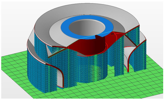
Figure 8.
Support structure for the realization of the impeller by using the SLM technique.
Finally, after printing, the functional model was inspected by using a digital caliper in order to verify the geometrical accuracy with which it has been reproduced. In particular, the selective laser melting process was considered successful if the thickness of the various sections of the impeller (Table 2) are fabricated with a maximum dimensional tolerance of ±0.1 mm [42].
3. Results and Discussion
3.1. Finite Element Analysis
The study of the stresses and deformations of the materials chosen for the printing processes (i.e., PET/FDM for the concept model and AISI 316L/SLM for the functional one) and for the AISI 304 of the original product was carried out through the finite element analysis (FEA) Autodesk Nastran-In-CAD software, within the Autodesk Inventor 2019 environment. To do so, a pressure load of 3 MPa distributed on the outer surface of an impeller blade was set (see Figure 6), corresponding to the highest prevalence of the pump during operation. The chosen mesh, as described in Section 2.2, is characterized by a total of 2767 nodes and 5325 elements.
The FEA has shown that the concentration of stresses is localized in a vertex of the blade, as reported in Figure 9 as a representative case. Obviously, as expected, the concept model produced with the FDM technique in PET, with a yield strength of 54.4 MPa, is far from being able to have mechanical characteristics suitable for the stresses to which the component is subjected in service (i.e., around 547 MPa (see Table 7)). On the other hand, the model in AISI 316L stainless steel to be produced by using the SLM technology has shown resistance characteristics similar to the original product made of AISI 304 stainless steel sheet: the total displacement is 0.0335 mm for AISI 316L against 0.0833 mm for AISI 304 and 6.017 mm for PET, as reported in Table 6.
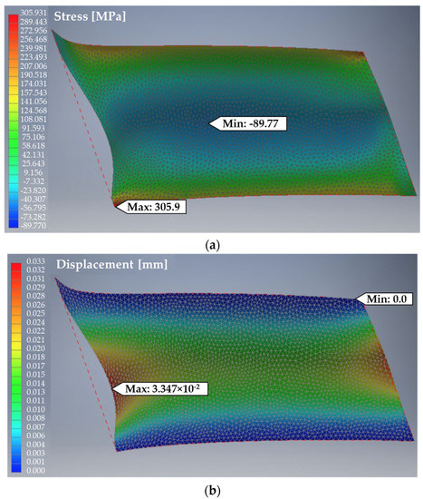
Figure 9.
FEA output for a single blade of the proposed impeller made of AISI 316L stainless steel sheet to be printed through SLM: (a) stress distribution (the maximum stress is on the bottom left corner); (b) total displacement.
Table 7.
Main FEA results for the three materials adopted (i.e., AISI 304 from the original impeller, PET for the concept model to be printed with the FDM technique, and AISI 316L for the functional model to be printed with the SLM technique).
As shown in Figure 9a, it is evident that the stress is mainly concentrated on the top and bottom side of the blade, corresponding to the joint with the upper and lower flared parts, respectively (as expected). Moreover, according to Table 6, it is worth noting that for both AISI 304 stainless steel and PET, the Von Mises stress is greater than the corresponding yield strength (see Table 3), therefore suggesting a possible rupture of the part. However, even if this can be considered plausible for PET due to its very low yield strength, it should be reconsidered for the AISI 304 stainless steel, due to the real application of such a configuration in commercially available submersible electric pumps. In fact, this high stress can be due to many reasons (e.g., that the mesh and/or the model are not accurate) and should be reinterpreted. Despite this, the obtained value can be considered acceptable since the deformation is reasonable and in line with that one obtained for the other material (i.e., 0.0833 mm against 0.0335 mm for the AISI 316L) [45,46].
3.2. 3D Printing
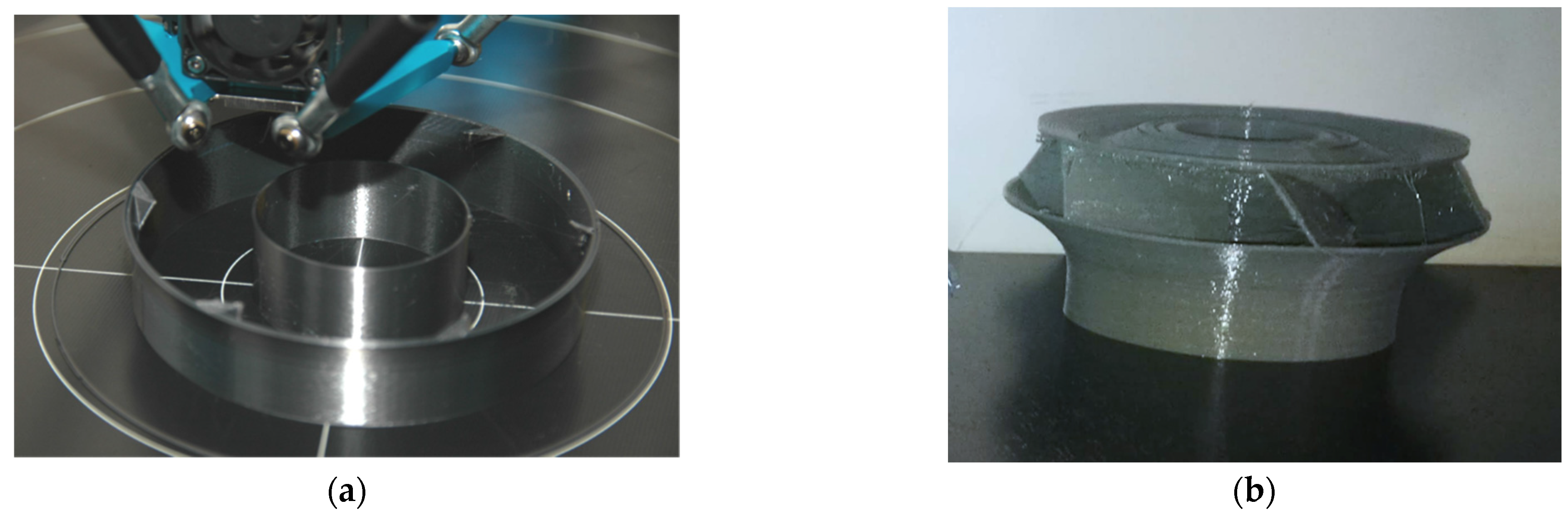
With a dimensional error of about 0.3 mm, as the result of the entire process chain from reverse engineering to printing, the concept model still allows verifying the applicability on the pump axis and in the diffuser seat. This is crucial to make the designer able to carry out the appropriate changes before the final printing of the functional model in SLM. The printing process was 15 h long. Figure 10 shows the concept model during and after printing.
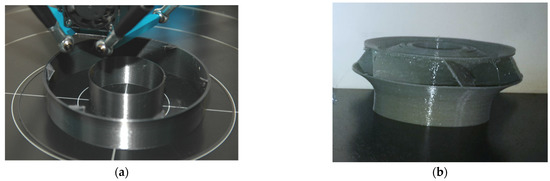
Figure 10.
Concept model printing of the impeller of a submersible electric pump through FDM technology by using PET as base material: (a) during and (b) after.
The functional model was printed through the SLM technology. The geometry of the impeller required the use of a lot of support material (as shown in Figure 8) which, requiring work to remove, made printing quite expensive (more than €1200.00 before taxes). However, the cost can be justified by the flexibility in changing the pitch angle of the blades and by the drastic reduction in costs related to the logistics of the pieces produced, making the solution in additive manufacturing interesting. Figure 11 shows the printed impeller.
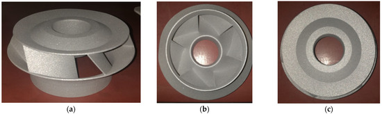
Figure 11.
Functional model of the impeller printed through the SLM technology by the service ZARE S.r.l.: (a) 3D view, (b) bottom view, and (c) top view.
Comparing the main dimensions of the 3D printed functional component with the original one made of stainless-steel sheets, negligible differences have been shown thanks to the ability to predict the volume shrinkage during SLM (around 2%), and therefore foreseeing an appropriate increased volume to be printed.
It is evident from Figure 11 that the functional model is characterized by a rough surface, which is around 8.5 µm (measured by using the mechanical profilometer Sloan Dektak 3030), against the typical values of laminated steel sheets less than 0.8 µm [47]. This can be critical for the chosen component, which should have a reduced surface roughness in order to guarantee the highest efficiency of the pump [48,49]. In fact, the enhanced surface roughness of SLM printed products is one of the main drawbacks of the technology [50,51,52]. Therefore, there is a need for a post-processing treatment aimed at obtaining the required surface roughness for the specific application, leading to a further increase in the final cost of the component. On the other hand, the typical mechanical characteristics of AISI 316L stainless steel pieces produced by SLM appear to be improved if compared with annealed samples, both in terms of hardness and tensile strength, but with lower ductility [53,54].
Table 8 reports the results of the geometrical accuracy. It suggests that the printing process follows the geometrical constraints of ±0.1 mm on the blade tolerances with respect to both the original and the CAD models. In fact, the absolute error, defined as the difference between the measured (average) and the target (from CAD model) values of the various thicknesses, is 1% for the blades and the upper flared part, while around 3% for the lower flared part.
Table 8.
Geometrical accuracy evaluation of the sections’ thickness of the 3D printed impeller through the measurement on three random points (indicated as #1, #2, and #3 for sake of simpleness). All the values are expressed in mm. “Std” stands for standard deviation; “Err” is the absolute error defined as the difference between the measured (average) and the estimated (from CAD model) values of the various thicknesses.
The greater deviation observed for the upper flared part with respect to the lower one (i.e., with standard deviations of 0.043 vs. 0.005, respectively) is due to the post-processing operations needed for the removal of the support structures. However, such a discrepancy can be reduced by means of a further finishing process ensuring a more constant thickness for all of the impeller’s sections.
Moreover, the SLM process allows reproducing the blades with an improved repeatability if compared with the traditional cutting and bending of sheet laminates used to produce the original impeller. In fact, the standard deviation obtained for the six blades’ thicknesses is around 0.030 for the original impeller (Table 2) and against around 0.018 for the 3D printed one.
Despite the fact that the thickness of the blades has been reduced from 1.60 mm to 1.29 mm in average, the total material volume of the impeller increased from ~4108 mm3 of the original one to ~6162 mm3 of the printed one. This is due to the increased value of the thickness of the lower flared part (1.93 mm against 1.82 mm in average) and the full densification of the upper one chosen in order to guarantee a greater resistance of these sections and, therefore, the success of the SLM printing process. As a result, the 3D printed pump impeller has a greater weight of around 1.5 times higher than the original one and a more robust design, allowing to operate velocities with the same stress thus generating increased head [55].
Moreover, the reduction of the thickness of the blades, together with the simplification of their geometry by avoiding the use of extra overhangs for bending and welding, results in an increased volume available for the fluid flow and therefore ensuring a higher flow rate, thus likely leading to an increased efficiency [56,57]. However, it is worth noting that the pump efficiency strictly depends on the total energy losses, which can originate from sources of different physical nature. Among all, the mechanical friction losses are of particular importance [56]. Therefore, since the surface of the blades, as well as all the surface of the impeller as a whole, are characterized by a high roughness, a decrease in the pump efficiency is expected [58,59] unless an appropriate finishing process is performed. But all of these aspects need further investigations, which were not part of the present study.
In general, the SLM technique could represent a suitable alternative for the production of mechanical parts with characteristics comparable to traditional production techniques, but still require further processing of the components for obtaining the required surface roughness for the chosen application (i.e., the reproduction of the impeller of a submersible electric pump). However, this study further needs the investigation of the actual performance of the impeller during operation in order to evaluate the efficiency of the pump.
4. Conclusions
This work aims at proposing and demonstrating a reverse engineering-based approach in order to reproduce the impeller of a submersible electric pump by using the selective laser melting 3D printing process.
First, a traditional manual measurement (i.e., through caliper and micrometer) for the evaluation of the actual dimensions of the impeller was adopted.
Then, after reconstructing the 3D model by modifying the thicknesses of the flared parts of the impeller and of the hanging between the blades and the flared parts, a finite element analysis was been carried out. The goal was to verify the suitability of both the proposed material (i.e., AISI 316L stainless steel instead of the AISI 304 stainless steel of the original impeller) and technology (i.e., SLM against sheet lamination and welding, for the final application). To this end, a pressure load of 3 MPa, which represent the highest prevalence of the pump during operation, was considered.
Before printing the functional component by SLM, a concept model was produced through the fused deposition modelling technique by using PET material in order to verify the applicability on the pump axis and in the diffuser seat.
The service ZARE S.r.l. has been used to produce the functional component by using the SLM technique. The biggest issue here was the use of a massive amount of support structures that need expensive post-production processes to be removed. Moreover, surface roughness is still a limit of the technology, with measured values of around 8.5 µm, requiring other post-processing operations and further increasing the final cost of the product.
Conversely, the SLM printing process allows the fabrication of highly-accurate geometries by ensuring the compliance with the imposed constraints of ±0.1 mm on the blade tolerances with respect to both the original and the CAD models. In fact, the absolute error evaluated for the various thicknesses is 1% for the blades and the upper flared part, while it is around 3% for the lower flared part.
The topographic optimization involved the reduction of the blades’ thickness from 1.60 mm to 1.30 mm, the full densification of the upper flared part and the increase in the thickness of the lower one from 1.82 mm to 1.90 mm in order to guarantee a greater resistance of these sections and therefore the success of the SLM printing process. As a result, the 3D printed pump impeller has a more robust design, allowing one to operate at higher speed while maintaining the same stress and therefore generating increased head. Moreover, an increased volume available for the fluid flow is obtained, thus ensuring a higher flow rate, which can lead to an increased pump efficiency.
Therefore, the SLM additive manufacturing technique allows for obtaining components with improved mechanical performances (i.e., hardness and tensile strength), if compared with the traditional laminated sheets, and the complete freedom to create complex objects in a single production process, capable of creating a pump perfectly suited to the customer’s needs with an undisputed positive impact on efficiency and energy consumption of the product.
The next step will be the use of the produced impeller under operating conditions in order to verify its actual suitability for the applications for which the submersible electric pumps are intended.
Author Contributions
Conceptualization, G.S.P., O.G., and S.G.; methodology, G.S.P.; software, M.H.; validation, G.S.P., F.T., and S.G.; formal analysis, G.S.P. and M.H.; investigation, G.S.P. and M.H.; resources, M.H.; data curation, G.S.P., F.T., and S.V.; writing—original draft preparation, G.S.P., F.T., and S.V.; writing—review and editing, G.S.P., F.T., S.V., M.H., O.G., and S.G.; supervision, O.G. and S.G. All authors have read and agreed to the published version of the manuscript.
Funding
This research received no external funding.
Institutional Review Board Statement
Not applicable.
Informed Consent Statement
Not applicable.
Data Availability Statement
Not applicable.
Acknowledgments
The authors gratefully acknowledge Arnaldo Luppino for the technical support.
Conflicts of Interest
The authors declare no conflict of interest.
References
- Kosky, P.; Balmer, R.; Keat, W.; Wise, G. Manufacturing Engineering. In Exploring Engineering; Elsevier: Amsterdam, The Netherlands, 2021; pp. 259–291. [Google Scholar]
- Zheng, J.; Zheng, W.; Chen, A.; Yao, J.; Ren, Y.; Zhou, C.; Wu, J.; Ling, W.; Bai, B.; Wang, W.; et al. Sustainability of unconventional machining industry considering impact factors and reduction methods of energy consumption: A review and analysis. Sci. Total Environ. 2020, 722, 137897. [Google Scholar] [CrossRef]
- Ion, J.C. Evolution of Laser Material Processing. In Laser Processing of Engineering Materials; Elsevier: Amsterdam, The Netherlands, 2005; pp. 12–40. [Google Scholar]
- Bhowmick, S.; Basu, J.; Majumdar, G.; Bandyopadhyay, A. Experimental study of plasma arc cutting of AISI 304 stainless steel. Mater. Today Proc. 2018, 5, 4541–4550. [Google Scholar] [CrossRef]
- Huang, Z.; Li, G.; Tian, S.; Song, X.; Sheng, M.; Shah, S. Theoretical Basis of Abrasive Jet. In Abrasive Water Jet Perforation and Multi-Stage Fracturing; Elsevier: Amsterdam, The Netherlands, 2018; pp. 1–62. [Google Scholar]
- Perumal, A.; Kailasanathan, C.; Stalin, B.; Rajkumar, P.R.; Gangadharan, T.; Venkatesan, G. Evaluation of EDM process parameters on titanium alloy through Taguchi approach. Mater. Today Proc. 2020. [Google Scholar] [CrossRef]
- Ghaffar, S.H.; Corker, J.; Fan, M. Additive manufacturing technology and its implementation in construction as an eco-innovative solution. Autom. Constr. 2018, 93, 1–11. [Google Scholar] [CrossRef]
- Pawar, S.S.; Bera, T.C.; Sangwan, K.S. Modelling of Energy Consumption for Milling of Circular Geometry. Procedia CIRP 2021, 98, 470–475. [Google Scholar] [CrossRef]
- Scharf, S.; Sander, B.; Kujath, M.; Richter, H.; Riedel, E.; Stein, H.; Tom Felde, J. FOUNDRY 4.0: An innovative technology for sustainable and flexible process design in foundries. Procedia CIRP 2021, 98, 73–78. [Google Scholar] [CrossRef]
- Kruth, J.P.; Leu, M.C.; Nakagawa, T. Progress in additive manufacturing and rapid prototyping. CIRP Ann. Manuf. Technol. 1998. [Google Scholar] [CrossRef]
- Molitch-Hou, M. Overview of additive manufacturing process. In Additive Manufacturing: Materials, Processes, Quantifications and Applications; Elsevier: Amsterdam, The Netherlands, 2018; pp. 1–38. ISBN 9780128121559. [Google Scholar]
- Tagliaferri, V.; Trovalusci, F.; Guarino, S.; Venettacci, S. Environmental and economic analysis of FDM, SLS and MJF additive manufacturing technologies. Materials 2019, 12, 4161. [Google Scholar] [CrossRef] [Green Version]
- Guarino, S.; Ponticelli, G.S.; Venettacci, S. Environmental assessment of Selective Laser Melting compared with Laser Cutting of 316L stainless steel: A case study for flat washers’ production. CIRP J. Manuf. Sci. Technol. 2020. [Google Scholar] [CrossRef]
- Hofer, A.-K.; Kraleva, I.; Bermejo, R. Additive manufacturing of highly textured alumina ceramics. Open Ceram. 2021, 5, 100085. [Google Scholar] [CrossRef]
- McCarthy, E.; Brabazon, D. Additive Manufacturing for Sustainability of Composite Materials Production. In Reference Module in Materials Science and Materials Engineering; Elsevier: Amsterdam, The Netherlands, 2021. [Google Scholar]
- Fernandes, R.R.; Tamijani, A.Y.; Al-Haik, M. Mechanical characterization of additively manufactured fiber-reinforced composites. Aerosp. Sci. Technol. 2021, 113, 106653. [Google Scholar] [CrossRef]
- Mehrpouya, M.; Vosooghnia, A.; Dehghanghadikolaei, A.; Fotovvati, B. The benefits of additive manufacturing for sustainable design and production. In Sustainable Manufacturing; Elsevier: Amsterdam, The Netherlands, 2021; pp. 29–59. [Google Scholar]
- Druzgalski, C.L.; Ashby, A.; Guss, G.; King, W.E.; Roehling, T.T.; Matthews, M.J. Process optimization of complex geometries using feed forward control for laser powder bed fusion additive manufacturing. Addit. Manuf. 2020, 34, 101169. [Google Scholar] [CrossRef]
- Barletta, M.; Gisario, A.; Mehrpouya, M. 4D printing of shape memory polylactic acid (PLA) components: Investigating the role of the operational parameters in fused deposition modelling (FDM). J. Manuf. Process. 2021, 61, 473–480. [Google Scholar] [CrossRef]
- Mehrpouya, M.; Gisario, A.; Nematollahi, M.; Rahimzadeh, A.; Baghbaderani, K.S.; Elahinia, M. The prediction model for additively manufacturing of NiTiHf high-temperature shape memory alloy. Mater. Today Commun. 2021, 26, 102022. [Google Scholar] [CrossRef]
- Rinaldi, M.; Caterino, M.; Manco, P.; Fera, M.; Macchiaroli, R. The impact of Additive Manufacturing on Supply Chain design: A simulation study. Procedia Comput. Sci. 2021, 180, 446–455. [Google Scholar] [CrossRef]
- Ford, S.; Despeisse, M. Additive manufacturing and sustainability: An exploratory study of the advantages and challenges. J. Clean. Prod. 2016, 137, 1573–1587. [Google Scholar] [CrossRef]
- Mukherjee, T.; DebRoy, T. Mitigation of lack of fusion defects in powder bed fusion additive manufacturing. J. Manuf. Process. 2018, 36, 442–449. [Google Scholar] [CrossRef]
- Moran, T.P.; Warner, D.H.; Phan, N. Scan-by-scan part-scale thermal modelling for defect prediction in metal additive manufacturing. Addit. Manuf. 2021, 37, 101667. [Google Scholar] [CrossRef]
- Durgashyam, K.; Indra Reddy, M.; Balakrishna, A.; Satyanarayana, K. Experimental investigation on mechanical properties of PETG material processed by fused deposition modeling method. Mater. Today Proc. 2019, 18, 2052–2059. [Google Scholar] [CrossRef]
- Yan, C.; Shi, Y.; Li, Z.; Wen, S.; Wei, Q. Typical applications of selective laser sintering technology. In Selective Laser Sintering Additive Manufacturing Technology; Elsevier: Amsterdam, The Netherlands, 2021; pp. 877–936. [Google Scholar]
- Song, B.; Wen, S.; Yan, C.; Wei, Q.; Shi, Y. Preparation and processing of metal materials. In Selective Laser Melting for Metal and Metal Matrix Composites; Elsevier: Amsterdam, The Netherlands, 2021; pp. 35–88. [Google Scholar]
- Cai, C.; Tey, W.S.; Chen, J.; Zhu, W.; Liu, X.; Liu, T.; Zhao, L.; Zhou, K. Comparative study on 3D printing of polyamide 12 by selective laser sintering and multi jet fusion. J. Mater. Process. Technol. 2021, 288, 116882. [Google Scholar] [CrossRef]
- Xu, Z.; Wang, Y.; Wu, D.; Ananth, K.P.; Bai, J. The process and performance comparison of polyamide 12 manufactured by multi jet fusion and selective laser sintering. J. Manuf. Process. 2019, 47, 419–426. [Google Scholar] [CrossRef]
- Saiga, K.; Ullah, A.S.; Kubo, A.; Tashi. A Sustainable Reverse Engineering Process. Procedia CIRP 2021, 98, 517–522. [Google Scholar] [CrossRef]
- Gisario, A.; Kazarian, M.; Martina, F.; Mehrpouya, M. Metal additive manufacturing in the commercial aviation industry: A review. J. Manuf. Syst. 2019, 53, 124–149. [Google Scholar] [CrossRef]
- Bauer, F.; Schrapp, M.; Szijarto, J. Accuracy analysis of a piece-to-piece reverse engineering workflow for a turbine foil based on multi-modal computed tomography and additive manufacturing. Precis. Eng. 2019, 60, 63–75. [Google Scholar] [CrossRef]
- Chougule, V.N.; Mulay, A.V.; Ahuja, B.B. Development of patient specific implants for Minimum Invasive Spine Surgeries (MISS) from non-invasive imaging techniques by reverse engineering and additive manufacturing techniques. Procedia Eng. 2014, 97, 212–219. [Google Scholar] [CrossRef] [Green Version]
- Segreto, T.; Bottillo, A.; Teti, R.; Galantucci, L.M.; Lavecchia, F.; Galantucci, M.B. Non-contact Reverse Engineering Modeling for Additive Manufacturing of Down Scaled Cultural Artefacts. Procedia CIRP 2017, 62, 481–486. [Google Scholar] [CrossRef]
- Panse, S.S.; Ekkad, S.V. Forced convection cooling of additively manufactured single and double layer enhanced microchannels. Int. J. Heat Mass Transf. 2021, 168, 120881. [Google Scholar] [CrossRef]
- Sun, C.; Wang, Y.; McMurtrey, M.D.; Jerred, N.D.; Liou, F.; Li, J. Additive manufacturing for energy: A review. Appl. Energy 2021, 282. [Google Scholar] [CrossRef]
- Rajenthirakumar, D.; Jagadeesh, K.A. Analysis of interaction between geometry and efficiency of impeller pump using rapid prototyping. Int. J. Adv. Manuf. Technol. 2009, 44, 890–899. [Google Scholar] [CrossRef]
- Chan, W.K.; Wong, Y.W.; Chua, C.K.; Lee, C.W.; Feng, C. Rapid manufacturing techniques in the development of an axial blood pump impeller. Proc. Inst. Mech. Eng. Part H J. Eng. Med. 2003, 217, 469–475. [Google Scholar] [CrossRef] [PubMed]
- Quail, F.J.; Scanlon, T.; Strickland, M. Development of a regenerative pump impeller using rapid manufacturing techniques. Rapid Prototyp. J. 2010, 16, 337–344. [Google Scholar] [CrossRef] [Green Version]
- JIA, D.; LI, F.; ZHANG, Y. 3D-printing process design of lattice compressor impeller based on residual stress and deformation. Sci. Rep. 2020, 10, 600. [Google Scholar] [CrossRef] [Green Version]
- Elizondo, A.; Reinert, F. Limits and hurdles of reverse engineering for the replication of parts by additive manufacturing (Selective laser melting). Procedia Manuf. 2019, 41, 1009–1016. [Google Scholar] [CrossRef]
- Adiaconitei, A.; Vintila, I.S.; Mihalache, R.; Paraschiv, A.; Frigioescu, T.; Vladut, M.; Pambaguian, L. A Study on Using the Additive Manufacturing Process for the Development of a Closed Pump Impeller for Mechanically Pumped Fluid Loop Systems. Materials 2021, 14, 967. [Google Scholar] [CrossRef] [PubMed]
- Huber, M.; Ess, J.; Hartmann, M.; Andreas, W.; Rettberg, R.; Kr, T.; Kaspar, L. Industrializing Additive Manufacturing—Proceedings of Additive Manufacturing in Products and Applications—AMPA2017; Meboldt, M., Klahn, C., Eds.; Springer International Publishing: Berlin/Heidelberg, Germany, 2018; Volume 1, ISBN 978-3-319-66865-9. [Google Scholar]
- Hitzler, L.; Hirsch, J.; Heine, B.; Merkel, M.; Hall, W.; Öchsner, A. On the anisotropic mechanical properties of selective laser-melted stainless steel. Materials 2017, 10, 1136. [Google Scholar] [CrossRef] [PubMed] [Green Version]
- Li, J.; Tang, L.; Zhang, Y. The influence of blade angle on the performance of plastic centrifugal pump. Adv. Mater. Sci. Eng. 2020, 2020. [Google Scholar] [CrossRef]
- Zhang, H.; Tang, L.; Zhao, Y. Influence of Blade Profiles on Plastic Centrifugal Pump Performance. Adv. Mater. Sci. Eng. 2020, 2020. [Google Scholar] [CrossRef]
- Peckner, D.; Bernstein, I.M. Handbook of Stainless Steels; McGraw-Hill: New York, NY, USA, 1977. [Google Scholar]
- Priegue, L.; Stoesser, T. The influence of blade roughness on the performance of a vertical axis tidal turbine. Int. J. Mar. Energy 2017. [Google Scholar] [CrossRef]
- He, X.; Jiao, W.; Wang, C.; Cao, W. Influence of Surface Roughness on the Pump Performance Based on Computational Fluid Dynamics. IEEE Access 2019, 7, 105331–105341. [Google Scholar] [CrossRef]
- Greco, S.; Gutzeit, K.; Hotz, H.; Kirsch, B.; Aurich, J.C. Selective laser melting (SLM) of AISI 316L-impact of laser power, layer thickness, and hatch spacing on roughness, density, and microhardness at constant input energy density. Int. J. Adv. Manuf. Technol. 2020, 108, 1551–1562. [Google Scholar] [CrossRef]
- Bernevig-Sava, M.A.; Stamate, C.; Lohan, N.M.; Baciu, A.M.; Postolache, I.; Baciu, C.; Baciu, E.R. Considerations on the surface roughness of SLM processed metal parts and the effects of subsequent sandblasting. In Proceedings of the IOP Conference Series: Materials Science and Engineering; Institute of Physics Publishing: Iasi, Romania, 2019; Volume 572, p. 012071. [Google Scholar]
- Ponticelli, G.S.; Giannini, O.; Guarino, S.; Horn, M. An optimal fuzzy decision-making approach for laser powder bed fusion of AlSi10Mg alloy. J. Manuf. Process. 2020, 58, 712–723. [Google Scholar] [CrossRef]
- Liverani, E.; Toschi, S.; Ceschini, L.; Fortunato, A. Effect of selective laser melting (SLM) process parameters on microstructure and mechanical properties of 316L austenitic stainless steel. J. Mater. Process. Technol. 2017, 249, 255–263. [Google Scholar] [CrossRef]
- Sun, Z.; Tan, X.; Tor, S.B.; Yeong, W.Y. Selective laser melting of stainless steel 316L with low porosity and high build rates. Mater. Des. 2016, 104, 197–204. [Google Scholar] [CrossRef]
- Ayad, A.F.; Abdalla, H.M.; El-Azm Aly, A.A. Effect of semi-open impeller side clearance on the centrifugal pump performance using CFD. Aerosp. Sci. Technol. 2015, 47, 247–255. [Google Scholar] [CrossRef]
- Stoffel, B. Physical and Technical Background of the Efficiency of Pumps. Assess. Energy Effic. Pumps Pump Units 2015, 45–61. [Google Scholar] [CrossRef]
- Yu, J.; Zhang, T.; Qian, J. Efficiency testing methods for centrifugal pumps. Electr. Mot. Prod. 2011, 125–172. [Google Scholar] [CrossRef]
- Bellary, S.A.I.; Samad, A. Exit Blade Angle and Roughness Effect on Centrifugal Pump Performance. In Proceedings of the ASME 2013 Gas Turbine India Conference GTINDIA 2013, Bangalore, India, 5–6 December 2013. [Google Scholar] [CrossRef]
- Wang, V.-H.; Li, K.-H.; Li, J.-Y. The influence of wall roughness on centrifugal pump performance. IOP Conf. Ser. Mater. Sci. Eng. 2021, 1081, 012054. [Google Scholar] [CrossRef]


Publisher’s Note: MDPI stays neutral with regard to jurisdictional claims in published maps and institutional affiliations. |
© 2021 by the authors. Licensee MDPI, Basel, Switzerland. This article is an open access article distributed under the terms and conditions of the Creative Commons Attribution (CC BY) license (https://creativecommons.org/licenses/by/4.0/).