Abstract
Due to the lack of information about the concept of Tons of Steering Pull (TSP) of many escort tugs, and the lack of research works relating the TSP demanded by a tethered vessel with respect to the TSP provided by tugs, the present paper shows an original study with mathematical models on how to solve these problems. What is more, an important percentage of the towing sector always employs Bollard Pull (BP), which is considered the only parameter capable of defining performance, so this paper aims to relate BP with TSP. The present research was carried out based on more than 25 escort tugs of different towing companies. Furthermore, a real case study of different tanker vessels was used for modelling purposes of tethered vessels’ TSP. Finally, once the proposed models were obtained, they were compared with International Maritime Organization (IMO) guidelines. The results showed charts with the main independent variables of tugs and vessels in order to be as useful and practical as possible to the shipping industry, mainly to ship owners and tug operators, from a safety point of view.
1. Introduction
For several decades, towing operations have been lucrative commercial activities and a relevant key of safety in the shipping industry [1,2]. Furthermore, the growing significance of the size of ships in the last years, which does not match with the increase of working areas of ports, makes it evident that the margin to safety has been reduced [3]. Therefore, considering that nowadays towing operations (ship assistance and escort towing) are vital from a safety point of view, it is even more important to known that in the event of an emergency situation, employed tugs are capable of providing the assistance necessary in order to avoid an accident [4,5,6].
Throughout the 1970s and 1980s, the state-of-the-art began to describe the tugs’ capabilities basing on polar diagrams of thrust vectors [7]. However, polar diagrams have two important handicaps to make an accurate comparison between tugs: they only represent tug capabilities at zero speed, and thrust capabilities are represented in a coordinate system referenced to the tugs themselves instead of being referenced to assisted vessels [8]. For this reason, although it is valid to analyse the abilities of tugs at very low speeds, they are not useful when assistances are carried out with an important forward speed. To overcome this lack of objective information from polar diagrams, in 2001, for the first time, researchers represented the forces generated by a purpose-built escort tug referred to as the Cartesian coordinate system of the assisted vessels [9]. This new diagram is known as a “butterfly” diagram, and through introducing the speed and the “appearance” of the tug, it is possible to read magnitudes of transverse (steering) and longitudinal (braking) forces generated on the assisted vessel at 360° and at different speeds. However, “butterfly” diagrams do not specify, for example, the displacement and the manoeuvrability of the escorted vessel. Therefore, forces generated by an escort tug can be sufficient to assist a particular vessel, but not to another, which would seriously jeopardise the overall safety of the operation.
On the other hand, BP only can be used to differentiate the capabilities at zero speed, because it is defined as the maximum force (thrust) exerted by the tug on a fixed towline in static condition [10,11,12]. Nowadays, this is the main parameter used to assess the capabilities of ship-handling tugs working at lower speeds, but if tugs have a certain speed over the water, BP will be different with respect to the static condition, mainly because at each speed, the hydrodynamic resistance consumes different energy.
This circumstance was more evident with the implementation of escorting assistance after the accident of m/v “Exxon Valdez” in 1989 and the consequent promulgation of the Oil Pollution Act in 1990 (OPA 90) [13,14,15]. It became clear that BP was not a good tool to assess the tugs’ capabilities during escorting assistance sailing at high speeds (above 6 knots) over long distances [16]. In these operations, the hydrodynamic lift from the tug’s hull will be used to develop a large force for transmitting through the rope into the tow [17], which is proportional to the tug’s hull underwater area and the square of transit speed [18,19]. Therefore, the performance of escort tugs must be defined, at least, by the capability to generate steering forces using indirect methods up to 10 knots [20,21]. This force, known as Tons of Steering Pull (TSP), is more important and higher than BP, and it corresponds to a steering force used to alter the vessel’s course in order to head it to a safe area; to help it to reduce the forward speed; or to counteract the effects of its rudder locked into a side, sailing at 10 knots [22,23,24].
Despite this, for many past decades and even nowadays, an important portion of the towing industry consider BP as the most important and only parameter that defines the characteristics of all types of tugs [4,25]. Professional works [26] confirm that tug owners publish little information about steering pull of tugs, so usually this information is estimated by multiplying BP by a figure that depends on the circumstance. In fact, even many tugs classified as Escort by a classification society do not have the TSP available in its ship’s particulars. Then, the lack of reliable information about the performance of escort tugs is evident from the genesis of this assistance mode. This can be observed in the simulation study carried out by Merrick (2002) [27] in order to assess, through dynamic models, the scheme escorting in Prince William Sound (Alaska), precisely the location where m/v Exxon Valdez suffered the accident. This work confirms the difficulty of reaching an agreement about the purpose of escort tugs after more than 8 years of discussions with all locally involved interests. More precisely, it was proposed that in some areas where two escort tugs were being employed, afterwards, only one escort tug was needed, but no performance characteristics of the involved tugs were specified. In other research works about models and simulations with tugs [6], the efficiency of escort tugs assisting the biggest vessels is connected only with BP and the size of tugs.
Following Molyneux et al. [28], and taking into account their length, escort tugs operate in off-design hydrodynamic conditions. For that, there is much research with model experiments focused on predicting the total forces generated and the limits of safe working. Furthermore, in the literature review, the reader can find many relevant studies concerning numerical simulations and proposed mathematical models of manoeuvring ships and tugs’ motion [29,30,31].
Regarding the tethered vessel, the manoeuvring performance, including the zigzag manoeuvres with different rudder angles, was also simulated in previous works research [26,32] with the objective of obtaining the yaw angle and lateral hull force, among others.
Regarding the influence of forces between the tug and the tethered ship, recent studies [3] use mathematical models to analyse the problems of forces generated in dynamic operations between both vessels considering the effects of drift and wind force, but in the port environment, i.e., under very low-speed conditions.
Although the research with mathematical models of forces affecting ships covers areas that are very different (hydrodynamic, hydrostatic, propulsion, and external forces), recent papers propose to develop synthetic and simple models of forces for its application to a ship in real-time mode [33]. This intention is in connection with the present work, that it is to find the simplest mathematical model able to relate the performance characteristics of tugs with the assisted vessels.
Tethered vessels must be always operated within the performance capabilities of escort tugs [26], and, therefore, the capabilities and requirements of both should be studied as a whole. However, as it can be observed in the literature revision, there are few research works that analyse, from a safety point of view, the requirements of assisted vessels together with capabilities and performance of tugs working as a unique element at high speeds. Furthermore, there is a lack of information about TSP in tugs, and BP is generally employed. Then, as the problem of relating ships’ characteristics and tugs’ performance has not been approached, the present paper aims to connect the tugs’ efficiency at different speeds (TSP of tugs) in relation to their BP, starting from the ships’ requirement (TSP of ships) and using different mathematical models. With this objective, this study proposes providing the shipping industry with new information to be used from two points of view. On one side, ship owners benefit from considering the BP tugs (always available) to know the TSP that a tug can exert to their vessels; as a consequence, they can select the type and the appropriate number of tugs to be employed. On the other side, tug operators benefit from knowing the BP needed of one or more tugs in order to satisfy the required TSP of escorted vessels as a function of their deadweight.
For this research, the next sections are composed of Materials and Methods, which describe the database used; the Results section, which makes use of ANOVA modelling, showing the graphs and the equations obtained; the Discussion section, which compares the results with the IMO ship requirements and; finally, the Conclusion section, which suggests further research that builds on the present work.
2. Materials and Methods
In the present paper, in order to relate the BP with TSP of the tugs, the main characteristics of more than 25 escort tugs of different towing companies were analysed, classified, and then modelled. Although this is not a number that is excessively high, mainly due to the limited number of escort tugs available in the world with their TSP published, it is a number that allows carrying out solid statistics analysis. The selected escort towing companies are located all over the world, and tugs are rendering assistance to vessels that are very different in size and characteristics. Furthermore, these tugs are employed in areas and under weather conditions very different between them, so they can be considered as representative of the escort towing fleet in the world.
Moreover, as it is also necessary to connect the TSP of tugs with the required TSP of escorted vessels, real cases data of different tanker vessels were selected and modelled, taking into consideration that each vessel has particular steering characteristics, which are a function of the speed and the steering angle [25,26,31]. Finally, after analysing the models’ errors, we show the relation between variables of tugs and assisted vessels.
In order to model the multiple variables involved, Minitab version 18 was selected [34,35].
The selected variables of tugs and units for the present research are included in Table 1.

Table 1.
Identification of tugs’ variables and used units.
The Type of Tug variable was codified with numerical values, as it can be seen in Table 2.
Table 2.
Codification of Type of Tug variable.
It was not necessary to codify the rest of the variables, so they were used with their own values, which were numerical values.
Finally, in order to compare our results with widely employed guidelines, we used the graphs of TSP published by the IMO, which were traced for oil tankers and LNG carriers sailing at 10 knots and considering the guidelines “Standards for Ship Manoeuvrability” [36,37]. These guidelines are recommendations only, and some authors [26] consider that in real cases, the needed TSP are higher than the theoretical values obtained in the graphs. However, other authors consider that the figures obtained from the graphs are excessive [38]. In any case, the scope of these works was not to analyse the reason for these discrepancies.
We used 10 knots as a reference value because it is considered by the literature as the reference escort speed. However, it is known that this speed only can be reached in certain areas of escort operations and sailing several nautical miles, because most seaports have the maximum speed established at 6–7 knots, corresponding to ship-handling assistance.
3. Results
Modelling
As it was mentioned in previous sections, many people with interest involved in the towing industry, even in the escort sector, associate the performance and capabilities of tugs directly with BP. After a previous analysis of normality and homoscedasticity of the more common variables employed to define the BP, some of them were identified by an ANOVA study to model BP. These variables were Type of Tug; Length (m); Beam (m); Depth (m); Draft (m); Speed (knots); Horsepower (HP); and Year Built.
Therefore, in the first stage of this research work, we developed a response surface to obtain a mathematical model able to calculate the estimated BP with the correlation between each of the previous variables. The model (1) obtained is shown in Equation (1).
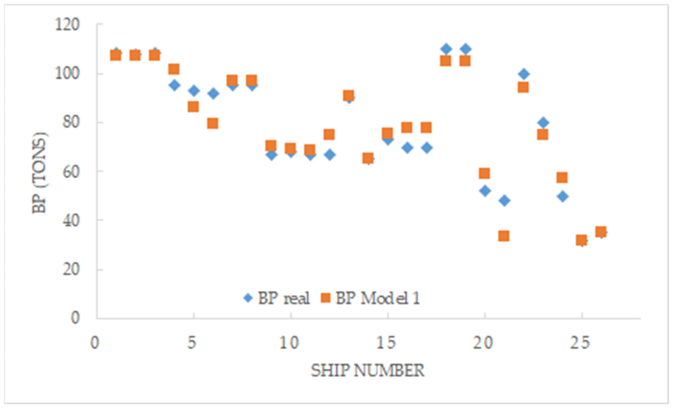
Units of BP obtained are in tons and, as it can be concluded from Figure 1, which represents the real BP of samples with BP obtained with this Model 1, a high precision is obtained: (R-square, 93.40%).
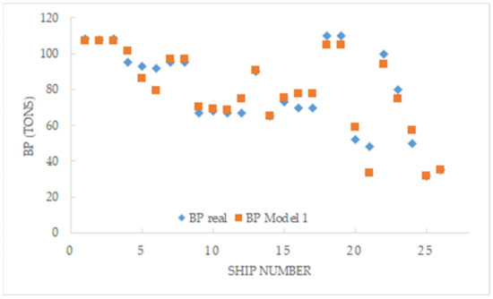
Figure 1.
Representation of tugs’ BP obtained with Model 1.
Considering that in the literature, we can find many different types of BP (as sustained BP, maximum static BP, marketing BP, or Brazilian BP) [11], the proposed model will be useful in order to calculate, with a very simple equation, the real BP. These data can be used in the next stage of the present research in the strange case that this information is not included in the tug’s particulars.
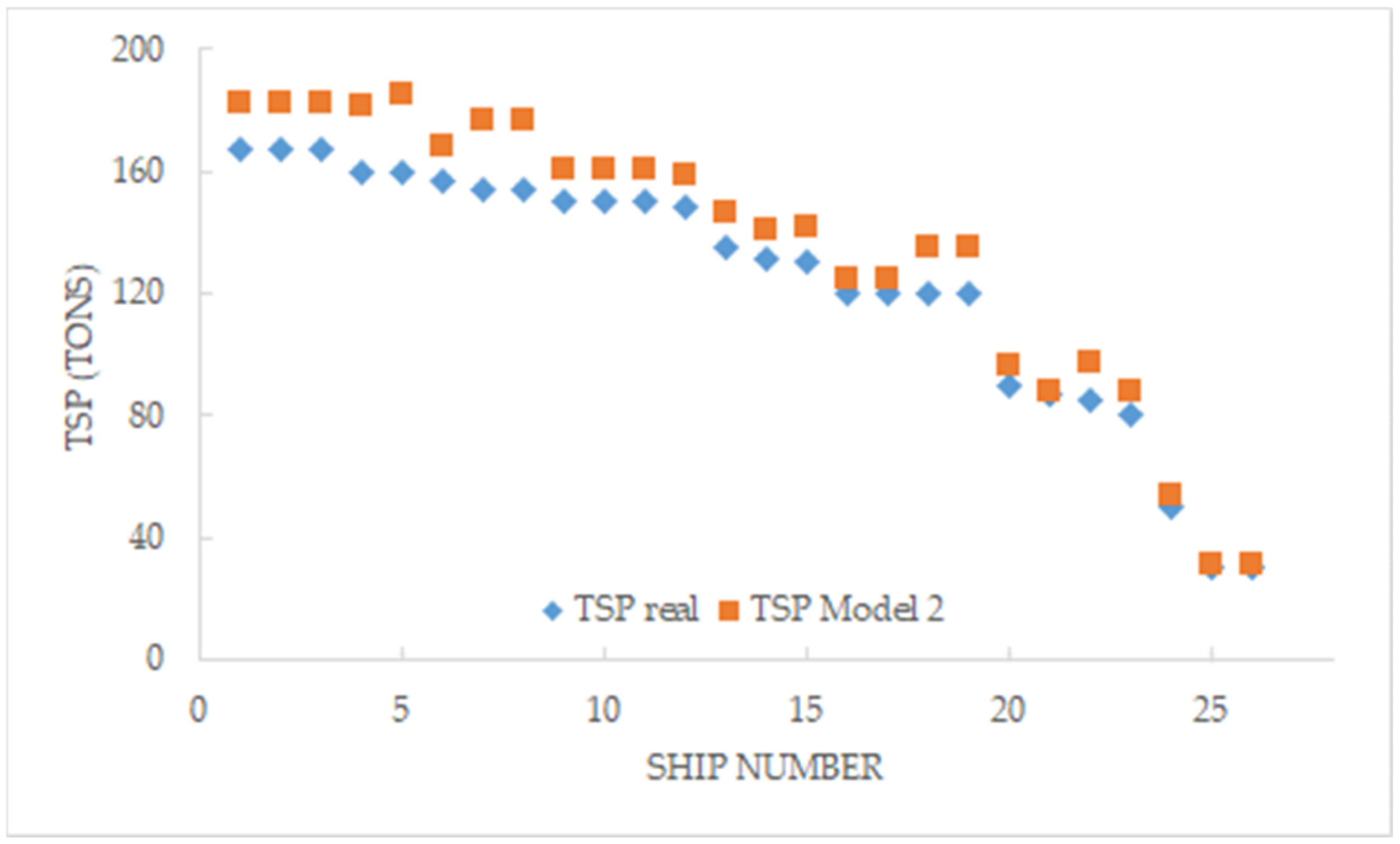
Therefore, although BP is usually published by tug owners, as it was commented previously, the same does not happen with TSP data. Therefore, here, we propose another response surface modelling in order to calculate the TSP of tugs at 10 knots, and considering the same variables of the previous model, which are usually known, i.e.: Type of Tug; Length (m); Beam (m); Draft (m); Depth (m); Tug Speed (Knots); Horsepower (BHP); and Year Built.
The regression equation of mathematical Model 2 obtained is included in Equation (2):
where the units TSP are tons, and a precision of 100% was obtained in R square. Figure 2 shows the good relation between real and estimated data of tugs’ TSP.

Figure 2.
Representation of tugs’ TSP real and obtained with Model 2.
Once the equations of BP and TSP are modelled with the tug’s usual data, a new regression equation was obtained including BP as a variable. This regression equation of Model 3 allows calculating the TSP developed by a tug at 10 knots as a function of only two independent variables: Tug Speed (knots) and BP (tons). The result of this model is Equation (3).
A determination factor of 80.01% for R-square indicates good precision. It can be also concluded from Figure 3, which plots the real TSP and the estimated TSP of tugs as per Model 3.
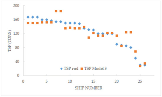
Figure 3.
Representation of tugs’ TSP real and obtained with Model 3.
Finally, it is interesting to comment on the validity range of the previous models and their variables, as it shown in Table 3.
Table 3.
Validity range of Models 1, 2, and 3.
In escort towing operations, as two ships are involved (the escort tug and assisted vessel), it is necessary to know the required TSP of the assisted vessel sailing at different speeds to be counteracted in the event of an emergency situation. Therefore, in this case, it is necessary to know the TSP needed by the escorted ship and the TSP developed effectively by the tug, in order to be sure that escort operations are being carried out with a sufficient margin of safety. Then, taking into consideration the rudder forces of different tankers registered in previous studies with the rudder blocked at various angles [28], we developed a mathematical model that allows us to calculate the TSP required by a ship relating the following independent variables: Deadweight; Ship Speed; and Rudder Angle. This data collection is included in Table 4.
Table 4.
TSP data in tons of different tanker vessels.
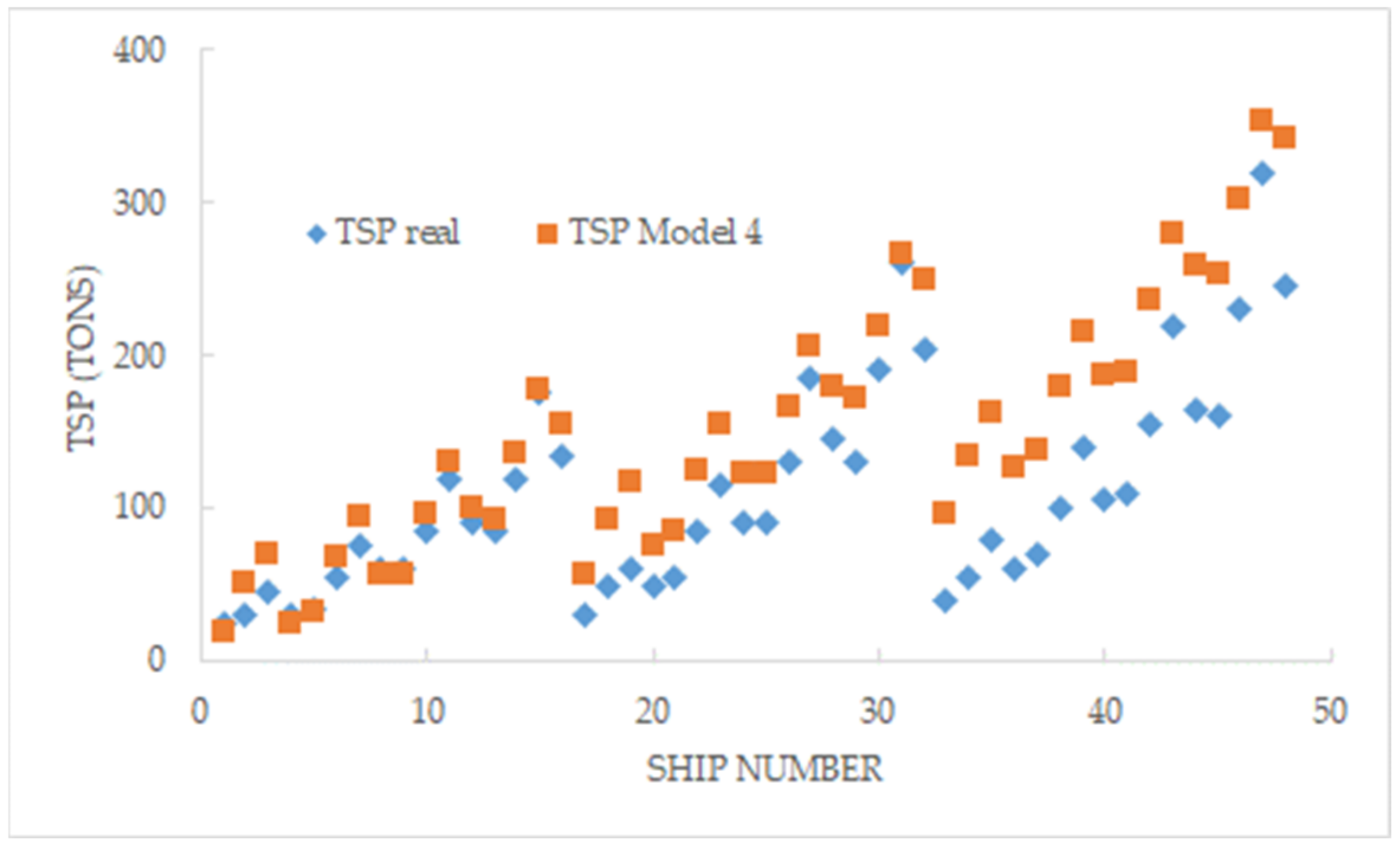
Equation (4) includes the result of Model 4 obtained:
where SS is ship speed in knots; DWT is deadweight in tons; and RA is rudder angle in degrees, being all variables referred to as tanker vessels. With this mathematical model, it we calculate the TSP (tons) required by a tanker with a precision of R-square of 96.69%, as can be seen from Figure 4.
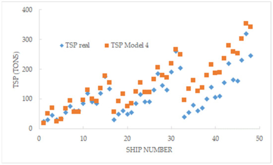
Figure 4.
Representation of tanker vessels’ real TSP and the corresponding TSP obtained with Model 4.
Once again, the validity range of Model 4 and its variables are shown in Table 5.
Table 5.
Validity range of Model 4.
4. Discussion
Models Analysis
From a safety point of view of towing operations, when vessels are being escorted, ship operators need to know if the tugs’ capabilities employed during the assistance match their needs of steering force. As it was previously mentioned, and unlike BP, the TSP of tugs are not always available, so the present section shows the relationship between both variables. Thus, anyone and at any time, without the need to carry out full-scale trials or complex simulations, can assess the tug TSP starting from their BP and vice versa.
To achieve this objective, Equation (3) of Model 3 was used to calculate TSP with a tug’s characteristics, and Equation (4) of Model 4 was used to calculate TSP with a ship’s particulars; then, these were matched with the objective of defining the tug BP variable as follows:
Therefore, Equation (5) allows us to define tug BP as a function of the required TSP of a tethered vessel using the deadweight, ship speed, and rudder angle as independent variables.
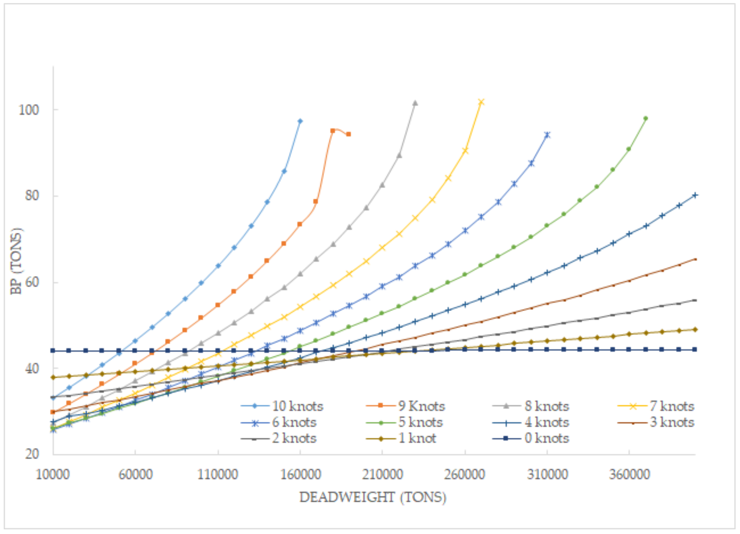
Considering that the literature review indicates that maximum steering forces (TSP) are required from a rudder angle of 25° [25], BP was calculated for series of assisted ship’s rudder angles of 15° and 25° according to Equation (5). In this simulation, the tug speed of 10 knots was considered as a constant. In each series, an individualised BP was calculated for each ship’s speed, from 10 knots to zero knots; once the escort tug begins to exert force, the ship’s speed will decrease progressively until it is under control. Therefore, more than 800 runs were tabulated, as can be seen in Figure 5 and Figure 6.
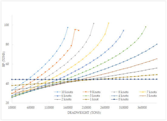
Figure 5.
Tug BP needed as a function of ship’s characteristics (constant rudder angle of 15°).
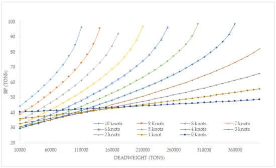
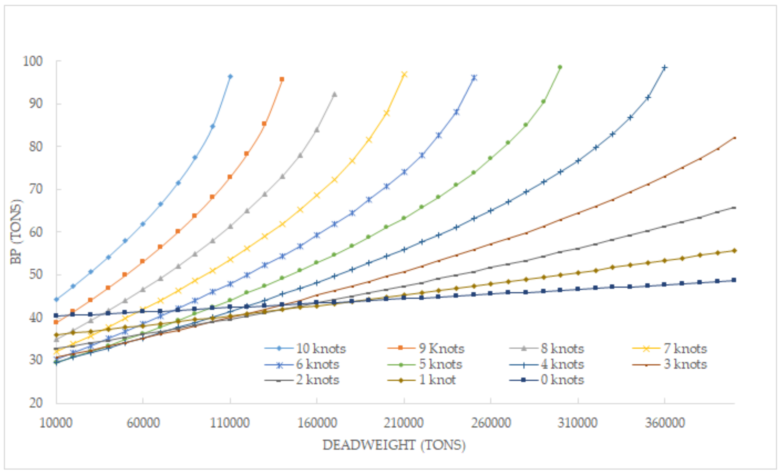
Figure 6.
Tug BP needed as a function of ship’s characteristics (constant rudder angle of 25°).
Figure 5 shows the BP needed from tugs to assist tethered tanker vessels sailing throughout the range of escort speeds with a rudder angle of 15°. Figure 6 represents the same but with a rudder angle of 25°.
If we now compare Figure 5 and Figure 6, it can be concluded that when the assisted ship is in static condition (zero speed), the BP hardly varies as a function of deadweight. This means that unlike the safety policy of many port authorities, which require excessive BP regardless of the type of traffic, it would not be necessary to employ tugs in ship-handling towing with BP as high as those currently used in many cases. In this circumstance, at zero speed, BP and TSP concur.
Furthermore, comparing both figures and at higher speeds, it is observed that the BP required is higher with a higher rudder angle (25°). This aspect would be in line with the literature stating that the maximum TSP required by an assisted vessel is produced with a rudder angle of 25°, and as a consequence, the corresponding BP needed from tugs.
On the other hand, taking into consideration the tendency of curves at higher speeds, especially with a rudder angle of 25°, it could be concluded that at present, there are no escort tugs available in the market with that BP required. Nevertheless, this circumstance is solved in real life using two tugs working in tandem [39], so the BP of each escort tug is added as it is regulated in Los Angeles/Long Beach port [40,41].
Another particular case of interest observed in both Figure 5 and Figure 6 is that except for 10 knots, in the range of lower deadweight, the BP required is lower than the BP required in static condition. Although this result could be considered illogical, it should be noted that these vessels are not sailing straight ahead, so the greater the rudder angle, the greater the yaw angle, and as a consequence, the greater the lateral surface of the underwater hull working against the flow of water. This hydrodynamic force will reduce the shipping speed and, therefore, tugs can control the TSP demanded with a lower BP.
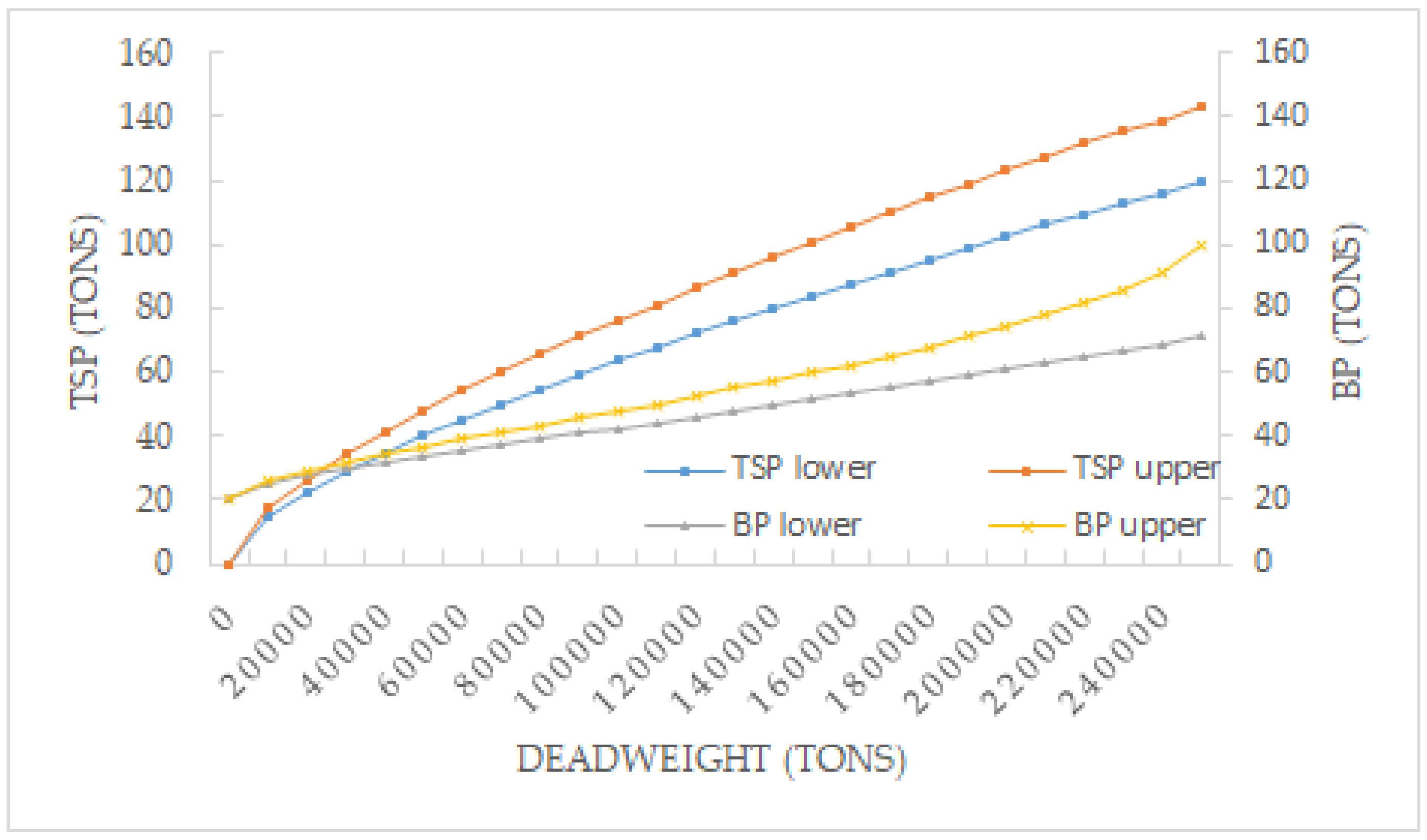
In order to know if our models satisfy the tools used by the towing industry at present, Figure 7 represents the IMO recommendations about upper and lower TSP limits required by a tanker vessel of different deadweight sailing at 10 knots.
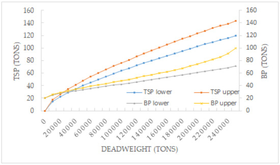
Figure 7.
IMO TSP limits and the corresponding BP limits as per Model 3.
As there are no published equations that define the IMO TSP limits, once we obtained several values of IMO graphs, they were used in our Model 3 in order to calculate the BP limits corresponding to IMO TSP limits. The results are also represented in Figure 7, which shows a good relationship between both variables.
In this sense, considering that the TSP provided by escort tugs are not always available, it is interesting to understand that starting from the TSP demanded by assisted vessels according to IMO, it is possible to assess the minimum BP (which are always available) that tugs would have to have to satisfy the TSP required.
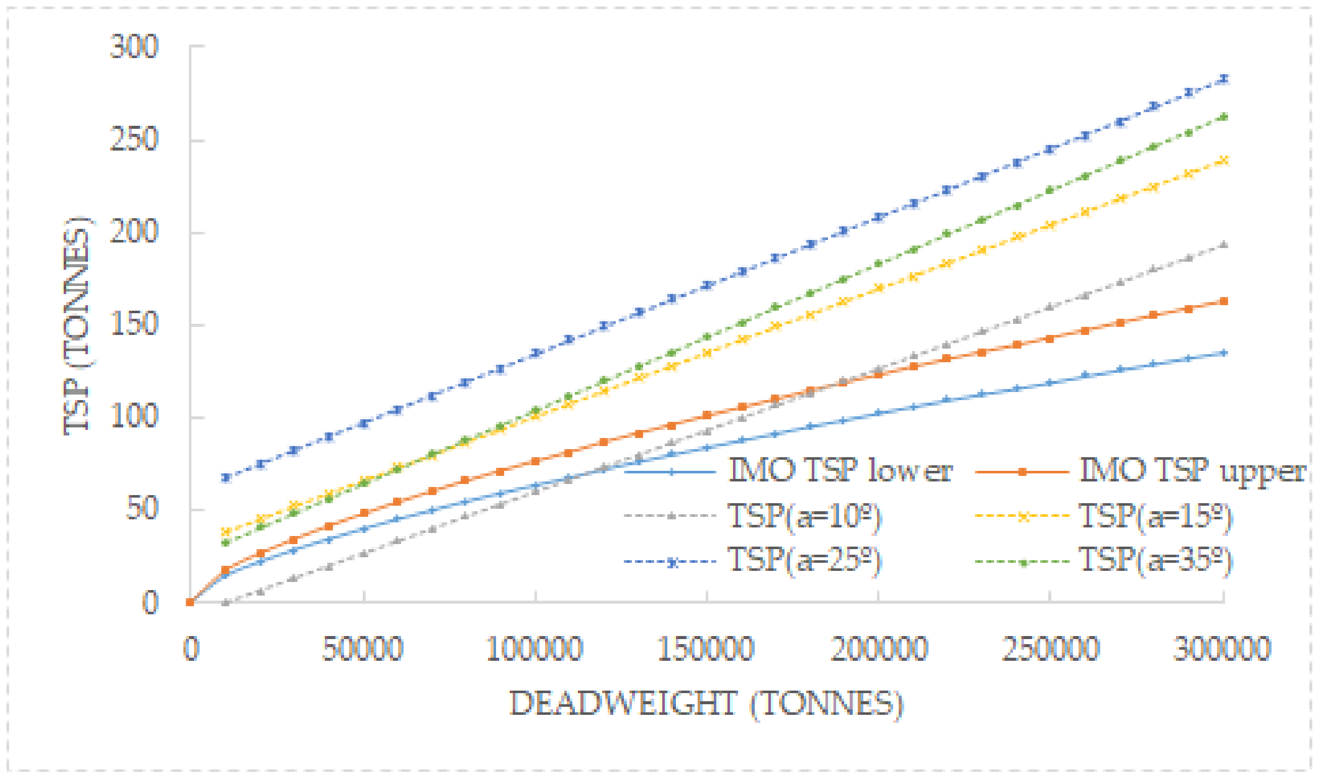
At the same time, with the objective of analysing the relation between IMO TSP and TSP demanded by a tanker vessel according to our Model 4, we developed a simulation of 160 runs for rudder angles of 10°, 15°, 25°, and 35°, where the ship speed variable was considered as constant (10 knots). From Figure 8, it can be concluded that IMO TSP limits correspond very well with our Model 4 when the tanker vessel is working with a rudder angle of 10°. Although in IMO TSP no information is published about rudder angles, this conclusion can be considered as acceptable taking into account that, calculating the correct wheel-over point, merchant vessels rarely steer with large angles of the rudder.
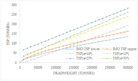
Figure 8.
IMO TSP limits and calculated TSP as per Model 4 for different rudder angles.
From Figure 8, it is also interesting to observe that at higher rudder angles, the TSP needed according to Model 4 is considerably higher than the upper limits of TSP required by IMO. This conclusion could be related to previous simulations and manoeuvring studies [26], where it is stated that the needed steering pull is 50% higher than upper IMO guidelines. Therefore, in the absence of more objective information that considers the navigation and manoeuvring characteristics of assisted vessels, the proposed models and the relationship between independent variables of tug and vessel could be useful for the towing sector.
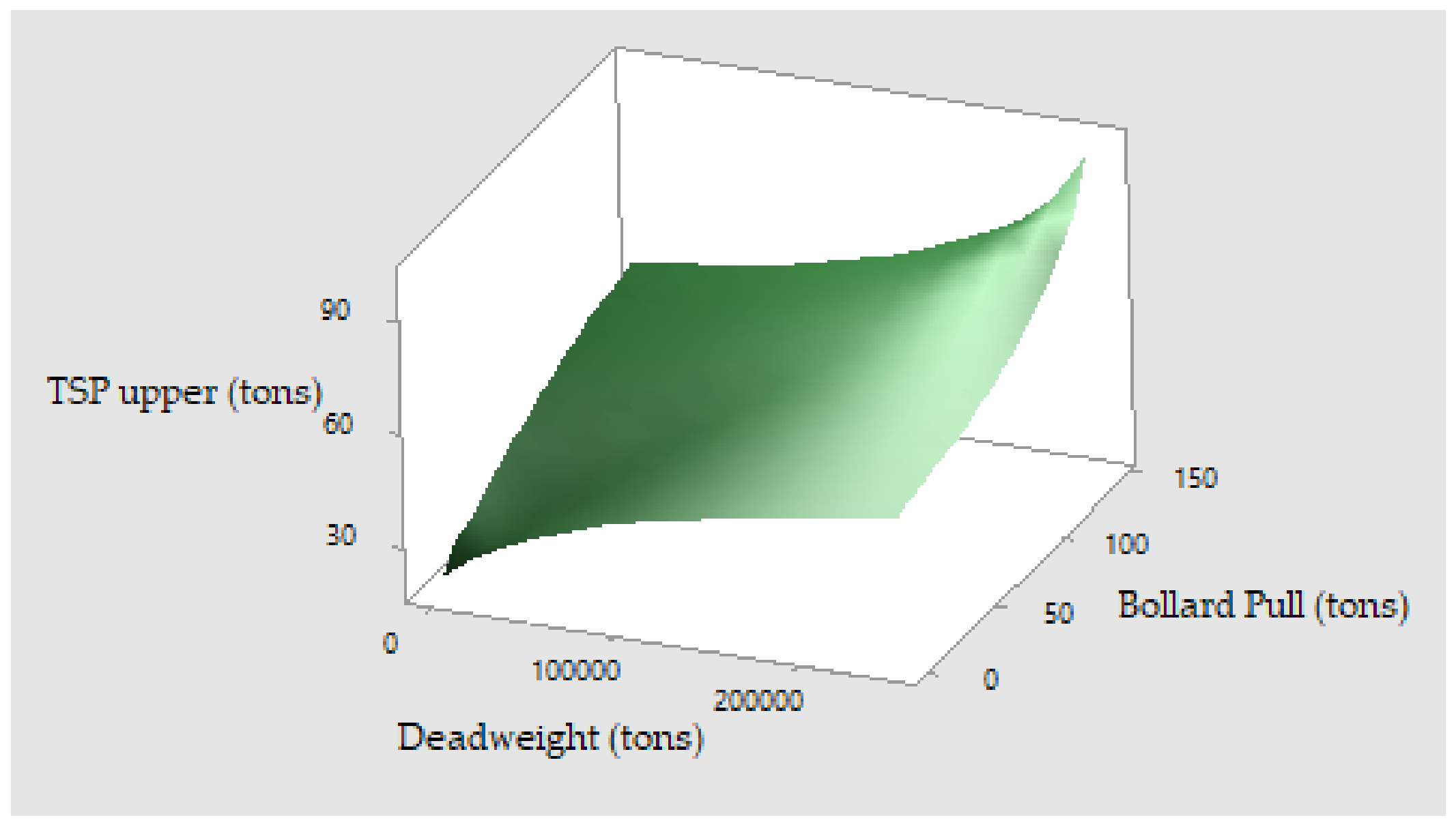
Finally, as it was previously mentioned, the parameter usually employed in order to classify a tug is BP. Therefore, this section intends to show and relate the main three variables playing in a tug–vessel system in a 3D map: deadweight of the tethered ship; tug BP and IMO TSP limits. For this mission, the upper and lower IMO TSP limits are deduced from its graphs, and tug BP considering the previous TSP is calculated following our Model 3. Figure 9 and Figure 10 represent the surface graphs where the appearance is very similar due to the difference between the upper and lower TSP limits being barely 20%.

Figure 9.
Surface graph for IMO TSP lower limit.

Figure 10.
Surface graph for IMO TSP upper limit.
5. Conclusions
With the genesis of escorting operations, it was soon shown that BP was not the only parameter that allows us to analyse the full performance of tugs, nor can it be used for comparative purposes between different tugs. Furthermore, as it is vital to know the TSP developed by an escort tug at different speeds (unknown many times), and given the lack of research works in the TSP subject, a case study with a number representative of an escort tug fleet was conducted. With this information, one mathematical model was proposed to ascertain BP; in the strange event that this parameter is not available or in case of doubts, a mathematical model was proposed to calculate TSP exerted by tugs based on their main characteristics, and another model was developed to ascertain the TSP of tugs using only two variables. One of these variables is BP, so this will allow us to relate TSP and BP. The last model proposed, employing a real case study, was used to obtain the TSP demanded by assisted vessels.
Considering that all the proposed mathematical models had a very good precision, afterwards, we matched the TSP equation demanded by tanker vessels with the TSP equation provided by tugs. In this way, the requirements of tugs expressed in BP can be obtained as a function of rudder angle and speed. Subsequently, using the third proposed model, IMO TSP is expressed in BP, i.e., the best-known parameter of a tug fleet. Finally, we carried out a comparison between the TSP IMO guidelines and the results of the proposed models, concluding that IMO guidelines should be over-reviewed in excess and/or considering the rudder angle maximum to be applied by the assisted ship.
Author Contributions
Conceptualisation, J.M.P.-C., J.A.O. and E.A.P.; methodology, J.M.P.-C., J.A.O. and E.A.P.; validation, J.M.P.-C., J.A.O. and E.A.P.; formal analysis, J.M.P.-C., J.A.O. and E.A.P.; investigation, J.M.P.-C., J.A.O. and E.A.P.; data curation, J.M.P.-C., J.A.O. and E.A.P.; writing—original draft preparation, J.M.P.-C., J.A.O. and E.A.P.; writing—review and editing, J.M.P.-C., J.A.O. and E.A.P. All authors have read and agreed to the published version of the manuscript.
Funding
This research was funded by the Spanish Ministry of Education and the University of A Coruña (Spain) in their research project to reduce energy consumption in ships (Grant No. 64900).
Institutional Review Board Statement
Not applicable.
Informed Consent Statement
Not applicable.
Data Availability Statement
Not applicable.
Acknowledgments
The authors wish to express their deepest gratitude to the Sustainability Specialisation Campus of the University of A Coruña for the administrative and technical support.
Conflicts of Interest
The authors declare no conflict of interest.
References
- Pulido Begines, J.L. Cuestiones Generales. In Los Contratos de Remolque Marítimo, 1st ed.; J. M. Bosch: Barcelona, Spain, 1996; pp. 27–129. [Google Scholar]
- Jayarathne, N.; Ranmuthugala, D.; Leong, Z. Safe tug operations during ship assist manoeuvres. J. Navig. 2019, 72, 813–831. [Google Scholar] [CrossRef]
- Wu, G.; Zhao, X.; Sun, Y.; Wang, L. Cooperative maneuvering mathematical modeling for multi-tugs towing a ship in the port environment. J. Mar. Sci. Eng. 2021, 9, 384. [Google Scholar] [CrossRef]
- Paulauskas, V.; Martynas Simutis, M.; Placiene, B.; Barzdžiukas, R.; Jonkus, M.; Paulauskas, D. The influence of Port Tugs on improving the navigational safety of the port. J. Mar. Sci. Eng. 2021, 9, 342. [Google Scholar] [CrossRef]
- Dongxing, X.; Xiufeng, Z.; Yong, Y. The computer simulation study of tug pushing operation system. In Proceedings of the 35th Chinese Control Conference (CCC), Chengdu, China, 27–29 July 2016; pp. 2074–2080. [Google Scholar]
- Figari, M.; Martinelli, L.; Martelli, M.; Enoizi, L.; Benedetto Piaggio, B. A new escort tug family designed to anticipate new safety requirements and operational needs. In Technology and Science for the Ships of the Future, 1st ed.; Marino, A., Bucci, V., Eds.; IOS Press: Amsterdam, The Netherlands, 2018; Volume 1, pp. 986–993. [Google Scholar] [CrossRef]
- Baer, W. Assessment of tug performance. In Proceedings of the First International Tug Conference; Troup, K.D., Ed.; Thomas Reed and Company Ltd.: London, UK, 1970; p. 4. [Google Scholar]
- Scalzo, S.; Hogue, D. Escort tug performance results. In Proceedings of the 14th International Tug and Salvage Convention; Troup, K.D., Ed.; Thomas Reed Publications: Surrey, UK, 1996; pp. 57–74. [Google Scholar]
- Gray, D.L. Development of tanker escort regulations in the United States with emphasis on the U.S. Pacific Coast. In Work Boat World, Asia 2001, Proceeding of the Singapore International Convention and Exhibition Centre, Singapore, 20–22 February 2001; Baird Publications: Melbourne, Australia, 2001. [Google Scholar]
- Brownlie, K. Controllable Pitch Propellers, 1st ed.; The Institute of Marine Engineers: London, UK, 1998; pp. 3–8. [Google Scholar]
- Jukola, H.; Skogman, A. Bollard Pull. In Proceedings of the 17th International Tug and Salvage Convention; Smith, A., Ed.; The ABR Company Limited: Wiltshire, UK, 2002; pp. 189–197. [Google Scholar]
- El Zaalik, M.A.A.; Kotb, M.A.; Sharara, A.I. Theoretical and experimental measurements of bollard pull with emphasis on propeller dimensions. Int. J. Multidiscip. Res. Dev. 2015, 3, 777–783. [Google Scholar] [CrossRef] [Green Version]
- Cohen, M. In the Wake of the Exxon Valdez. The Oil Pollution Act of 1990. An Analysis. In Proceedings of the 11th International Tug Convention and Marine Salvage Symposium; Troup, K.D., Ed.; Thomas Reed Publications: Surrey, UK, 1990; pp. 5–28. [Google Scholar]
- Jansen, M. Paradigm Shifts in Tugnology. In Proceedings of the 23rd International Tug, Salvage & OSV Convention and Exhibition; Gorman, D., Ed.; The ABR Company Ltd.: Wiltshire, UK, 2014; pp. 245–249. [Google Scholar]
- Allan, R.G. The Evolution of Tug Design through ITS Eyes. In Proceedings of the 25th International Tug and Salvage Convention and Exhibition; Wraight, C., Bury, J., Eds.; The ABR Company Ltd.: Wiltshire, UK, 2018; pp. 31–50. [Google Scholar]
- Allan, R. The evolution of escort tug technology: Fulfilling a promise. SNAME Trans. 2000, 108, 99–122. [Google Scholar]
- Baniela, S.I.; Melón, G.E. The Voith turbo fin (VTF) a new system to improve the performance of escort tractor Voith Tug. J. Navig. 2006, 59, 505–519. [Google Scholar] [CrossRef]
- Artyszuk, J. Types and power of harbour tugs. The latest trends. Pr. Nauk. Politech. Warsz. Transp. 2013, 98, 9–20. [Google Scholar]
- Noble, J.M. Bollard Pull–Fact or Fiction. How the experts determine tow Requirements. In Proceedings of the 18th International Tug and Salvage Convention; Smith, A., Ed.; The ABR Company Ltd.: Wiltshire, UK, 2004; pp. 75–80. [Google Scholar]
- Piaggio, B.; Martelli, M.; Viviani, M.; Figari, F. Manoeuvring model and simulation of the non-linear dynamic interaction between tethered ship and tug during escort. In Proceedings of the Maritime Transportation and Harvesting of Sea Resources, Lisbon, Portugal, 9–11 October 2017. [Google Scholar]
- Iglesias-Baniela, S.; Vinagre-Ríos, J.; Pérez-Canosa, J.M. Ship handling in unprotected waters: A review of new technologies in escort tugs to improve safety. Appl. Mech. 2021, 2, 46–62. [Google Scholar] [CrossRef]
- Allan, R.; Molyneux, D. Escort tug design alternatives and a comparison of their hydrodynamic performance. Trans. Nav. Soc. Nav. Archit. 2004, 112, 191–205. [Google Scholar]
- DNV·GL. Full Scale Testing of Escort Vessels. Class Guideline DNVGL-CG-0155. February 2016. Available online: http://www.dnvgl.com (accessed on 10 June 2021).
- Van Kasteren, J. The ART of tugnology: The ultimate balance between safe ship assist and safe escort duties. Rotor Tug 2012, 1, 1–11. [Google Scholar]
- Hensen, H. Tug Use in Port. A Practical Guide. Including Port. In Port Approaches and Offshore Terminals, 3rd ed.; The ABR Company Ltd.: Wiltshire, UK, 2018; pp. 235–263. [Google Scholar]
- Bay, J.; Schultz, S. Manoeuvring Study of Escorted Tankers to and from Kitimat. In Real-Time Simulations of Escorted Tankers Bound for a Terminal at Kitimat, 1st ed.; Force Technology: Lyngby, Denmark, 2010. [Google Scholar]
- Merrick, J.R.W. Evaluation of tug escort schemes using simulation of drifting tankers. Simulation 2002, 78, 380–388. [Google Scholar] [CrossRef]
- Molyneux, D.; Xu, J.; Bose, N. Flow vectors around an escort tug at a large yaw angle. In Proceedings of the Canadian Marine Hydrodynamics and Structures Conference, St. John’s, NL, Canada, 16–17 October 2017. [Google Scholar]
- Yoshimura, Y. Mathematical model for manoeuvring ship motion (MMG Model). Proceeding of the Workshop on Mathematical Models for Operations involving Ship-Ship Interaction, Tokyo, Japan, 4–5 August 2005. [Google Scholar]
- Sutulo, S.; Guedes-Soares, C. Mathematical models for simulation of manoeuvring performance of ships. In Marine Technology and Engineering, 1st ed.; Guedes-Soares, C., Garbatov, Y., Fonseca, N., Texeira, A.P., Eds.; CRC Press: Boca Raton, MA, USA, 2011; pp. 661–699. [Google Scholar] [CrossRef]
- Tzeng, C.-Y.; Chen, J.-F. Fundamental properties of linear ship steering dynamic models. J. Mar. Sci. Technol. 1999, 7, 79–88. [Google Scholar]
- Aksu, E.; Köse, E. Evaluation of mathematical models for tankers’ maneuvering motions. J. ETA Marit. Sci. 2017, 5, 95–109. [Google Scholar] [CrossRef]
- Sen, D.O.; Vinh, T.C. Developing mathematical model for calculating forces affecting to Ship motions. Fluid Mech. Res. Int. 2018, 2, 66–71. [Google Scholar] [CrossRef] [Green Version]
- Minitab v.18. Response Surfaces. Available online: https://support.minitab.com/en-us/minitab/18/help-and-how-to/modeling-statistics/doe/supporting-topics/response-surface-designs/response-surface-central-composite-and-box-behnken-designs (accessed on 29 July 2021).
- Orosa, J.A.; Costa, A.M.; Vergara, D.; Fraguela, F. The influence of climate parameters on maintenance of wind farms—A Galician case study. Sensors 2021, 21, 40. [Google Scholar] [CrossRef] [PubMed]
- International Maritime Organization, IMO 2002 Standards for Ship Manoeuvrability. Maritime Safety Committee (IMO MSC), 76th Session, Agenda Item 23. Report on the Maritime Safety Committee on its Seventy-Sixth Session, MSC 76/23/Add.1. Annex 6, Resolution MSC.137 (76) (Adopted on 4 December 2002), 1–6. London, UK, 18 December 2002. Available online: https://wwwcdn.imo.org/localresources/en/KnowledgeCentre/IndexofIMOResolutions/MSCResolutions/MSC.137(76).pdf (accessed on 2 August 2021).
- Davis, H.; Polawski, M. Classification Society Tug Review for Prince William Sound Regional Citizens’ Advisory Council, 1st ed.; Det Norske Veritas: Sunrise, FL, USA, 2011. [Google Scholar]
- Allan, R.G. A Review of Best Available Technology in Tanker Escort Tugs. Project 212-090; Revision 3; Robert Allan Ltd.: Vancouver, BC, Canada, 2013. [Google Scholar]
- Baniela, S.I.; Díaz, A.P. The first escort tractor Voith tug with a bulbous bow: Analysis and consequences. J. Navig. 2008, 61, 143–163. [Google Scholar] [CrossRef]
- Schisler, V.J.; Brooks, G. Team Towing: Using Relatively Small Tractors on Heavy Ships. Professional Mariner 2001. Available online: http://www.towingsolutionsinc.com (accessed on 9 June 2021).
- California Code of Regulations. Title 14, Division 1. Subdivision 4, Office of Spill Prevention and Response Chapter 4. Vessel Requirements. Subchapter 2. Tank Vessel Escort Program for the Los Angeles/Long Beach Harbor. Sections 851.20–851.32. August 2012. Available online: https://wildlife.ca.gov/OSPR/Legal/OSPR-Regulations-Index (accessed on 2 August 2021).


Publisher’s Note: MDPI stays neutral with regard to jurisdictional claims in published maps and institutional affiliations. |
© 2021 by the authors. Licensee MDPI, Basel, Switzerland. This article is an open access article distributed under the terms and conditions of the Creative Commons Attribution (CC BY) license (https://creativecommons.org/licenses/by/4.0/).