Article

Are We Able to Print Components as Strong as Injection Molded?—Comparing the Properties of 3D Printed and Injection Molded Components Made from ABS Thermoplastic

Institute of Metrology and Biomedical Engineering, Faculty of Mechatronics, Warsaw University of Technology, 8 Sw. A. Boboli St., 02-525 Warsaw, Poland
*
Author to whom correspondence should be addressed.
Appl. Sci. 2021, 11(15), 6946; https://doi.org/10.3390/app11156946
Submission received: 28 June 2021 / Revised: 23 July 2021 / Accepted: 26 July 2021 / Published: 28 July 2021

Abstract

:

Featured Application

The presented results can be introduced in the design stage of the polymer and composite elements for additive manufacturing to achieve the highest mechanical strength, comparable with corresponding parts fabricated with the injection molding technique.

Abstract

In this paper, we are focusing on comparing results obtained for polymer elements manufactured with injection molding and additive manufacturing techniques. The analysis was performed for fused deposition modeling (FDM) and single screw injection molding with regards to the standards used in thermoplastics processing technology. We argue that the cross-section structure of the sample obtained via FDM is the key factor in the fabrication of high-strength components and that the dimensions of the samples have a strong influence on the mechanical properties. Large cross-section samples, 4 × 10 mm2, with three perimeter layers and 50% infill, have lower mechanical strength than injection molded reference samples—less than 60% of the strength. However, if we reduce the cross-section dimensions down to 2 × 4 mm2, the samples will be more durable, reaching up to 110% of the tensile strength observed for the injection molded samples. In the case of large cross-section samples, strength increases with the number of contour layers, leading to an increase of up to 97% of the tensile strength value for 11 perimeter layer samples. The mechanical strength of the printed components can also be improved by using lower values of the thickness of the deposited layers.

1. Introduction

Additive techniques are gaining more and more attention in the manufacturing process of components and prototypes, with the FDM technique (fused deposition modeling) leading in the fabrication of polymer components [1,2]. The FDM technique uses thermoplastic polymers. Fused/plasticized material is applied layer by layer according to the generated program based on computer-aided design. The resulting element is not monolithic compared with injection molded parts: it consists of contour layers generated in place of the element perimeters and partially hollow infill in the internal structure.
For several years, intensive research has been carried out to determine the mechanical properties of the elements produced with the FDM technique. These experiments aimed at assessing the influence of printout direction during the formation process to obtain the highest possible mechanical properties. The main focus of such research is to evaluate the infill density, the infill pattern, and orientation of deposited layers and their influence on the mechanical properties of 3D printed components [1,3,4]. Additionally, the influence of layer height has been evaluated [5,6]. To this day, these process elements are the key factor considered in the fabrication of large-scale 3D printed components and the optimization of the additive process.
From analysis of the literature, we can argue that maximum infill volume is not always recommended. After the infill exceeds 50%, the strength value stabilizes at a certain level [7], and further increase does not affect the strength significantly, while the printing time increases drastically [6]. The types of infill patterns used during the fabrication process in relation to the movement directions of the printing head are presented in the literature [6]. It turns out that the selection of a specific infill type affects the mechanical properties. The most widely discussed problem is related to the orientation of the printed component on the support table. The influence of the sample alignment affecting the direction of the printing on the mechanical properties is evaluated in the literature, and results suggest that the lowest strength values of the formed elements are recorded in the direction of layer growth, which is the Z-axis for fused deposition modeling process [8,9].
What is missing in the literature is detailed studies on the influence of contour layer thickness on the mechanical strength of printed components. Only a handful of studies suggest that increasing the value of perimeter layers improves mechanical strength. Still, no deep analysis of the problem is presented, and no attempt has been made to compare the results of samples printed with different cross sections. In many publications, authors use standard sample shapes without deep analysis of additional geometric factors. For the first time, we compare the difference between the mechanical properties of samples with different cross sections fabricated with the same formation parameters.

2. Materials and Methods

Colorless ABS thermoplastic material (poly(acrylonitrile-co-butadiene-co-styrene) was acquired from Plastaw, Poland, in the form of 1.75 mm filament rod. Due to the lack of defined standards for inspection of additively fabricated components, the standards for tensile strength test in injection molding of thermoplastics were used: ISO 527-1:2012, ISO 3167:2014 and ISO 294:2017. The detailed dimensions of the dog bone specimens type 1A (Figure 1a) and type 5A (Figure 1b) are listed in Table 1. The sample types 1A and 5A were selected for experiments to compare the effect of additive forming on the samples with a different cross section (dimensions).
The design of the test samples was prepared in Autodesk Inventor CAD and exported to the STL format file. Next, the MakerBot Print slicer generated a G-code to control the FDM 3D printer. The samples were printed with ABS on a commercial, low-end FDM printer, CTC Bizer 2X PRO series dual nozzle 3D printer from CTC Electronic, Zhuhai, China. Samples were printed individually with the following parameters:
-
print speed 40 mm/s,
-
head temperature 280 °C,
-
nozzle diameter 0.4 mm,
-
table temperature 110 °C.
Corresponding samples with the same geometry were injection molded from the same ABS material (granulated for molding), on the Boy 15 S, single screw injection molding machine, from Dr. Boy GmbH, Neustadt-Fernthal, Germany, with corresponding process parameters:
-
material temperature 170 °C,
-
mold temperature 40 °C,
-
pressure 100 MPa.
Tensile strength tests were performed using a QC-506B1 universal testing machine, from Cometech Testing Machines Co., Ltd., Taiwan, at a speed of 2 mm/min to observe the behavior of the samples during extension.

3. Results

For the procedure samples printing, the hexagonal infill pattern and the different number of contour layers were selected, presented in Figure 2 and Figure 3, respectively. The infill density of the samples was set to 30%, 50%, 70%, 90%, and 100%, while the number of contour layers was set to 3, 5, 7, 9, and 11. For all configurations of infill volume and contour layers, five samples were prepared of each type. Results presented in the tables and figures are the average values calculated from the measurements, with additional error bars covering the highest and lowest measured values.
The orientation of the printed samples on the support table is presented in Figure 4. The most common arrangement for the fabrication of 3D printed models is “flat” (Figure 4b), but we also wanted to evaluate other printing directions. Therefore, the following orientation for printing was “horizontal” (Figure 4a), followed by building along the Z-axis, “vertical” (Figure 4c). Such orientation of the samples allows the different arrangement of the infill inside the samples and a different number of perimeter layers. With such preparation of samples, we were able to evaluate the influence of the printing direction on the mechanical properties. Additionally, Figure 5 shows the differences in cross sections of samples depending on the number of contour layers and the type of sample (1A or 5A).
Tensile strength tests depending on the printing orientation of the samples on the working table are presented in Figure 6. Samples were printed with a layer height of 0.2 mm, three layers of contour, and 50% infill density. For comparison, the results of the injection molded parts are denoted on the graph.
The influence of the infill density of printed samples was also analyzed (Figure 7). A comparison is presented for the same printing parameters as previously prepared for the 1A test samples printed in “flat” orientation. The infill pattern for individual samples is presented in Figure 2. Once again, for comparison, the results of the injection molded parts are denoted.
The effect of infill density and the number of contour layers on the “flat” printed samples are compared in Figure 8. We can observe a significant influence of the contour on the infill inside the printed samples, which is illustrated in Figure 3 and Figure 5.
Comparative results for both types of test samples (1A and 5A) with different infill densities printed in the “flat” orientation are presented in Figure 9. In both sample types, the number of contour layers was three. This limitation in layer number was due to the cross section of the 5A fitting, having geometric limitations, which are visible in Figure 5f. A small cross-section area of the sample was limited to a maximum of three contour layers. More layers would have resulted in the 100% infill of the sample, an unfavorable situation for our experiments, influencing the g-code generation algorithm in the slicer tool. This situation is described in details in the Discussion section.
The analysis of the impact of deposited layer thickness on the mechanical strength of samples printed in the “flat” orientation is presented in Figure 10. Here, type 5A samples were prepared with three contour layers and a constant infill density of 70%. During the printing process, the width of the material fed through the nozzle did not change, only the height of the applied layer. It was necessary to check what effect this parameter had on the tensile strength of elements formed in additive technology.

4. Discussion

The results obtained with different orientation of samples on the worktable are presented in Figure 6, compared with similar samples fabricated by injection molding (Table 2) [10]. The best results were obtained for samples printed with the horizontal orientation, according to Figure 4, which had 65% of the strength compared with the injection molded samples. Similar results are presented in the literature [8,9,11]. Despite the best values of the mechanical strength, this method of sample fabrication has some drawbacks related to the printing of additional supports, extending the printing time. The “flat” orientation eliminates the problem of supports and at the same time obtains 60% of the strength noted for injection molded samples. The least resistant samples were oriented vertically to the worktable, having only 33% strength of the injection molded parts. Additionally, we did not observe breakage of the samples but slow delamination of the layers printed, in the same direction as the applied force. Comparing samples printed with different orientations, we can conclude that the samples built along the Z-axis (vertical) had around 50% of the strength of the remaining samples. Such a phenomenon is due to a significantly lower binding strength between the applied layers (vertical print) compared with the strength of the layer itself (flat, horizontal) [9]. This clearly indicates that the deposition direction of layers in the FDM process (and other additive processes) is of great importance for the strength of the “printed” model [12,13]. This suggests that it is necessary to determine the directions of the load within the printed parts during the design process and apply the most optimal orientation of the printouts on the worktable during the FDM forming process.
Due to the small difference in the strength values of the samples printed in “flat” and “horizontal” orientation (less than 5%) and the additional process drawback of printing the support material for horizontal samples, further tests were performed with a flat pattern. The strength tests were performed for the samples with different infill density (Figure 7). Results of the tensile stress test of printed samples with the different infill density are presented in Table 3. An increase in the infill density resulted in an increase in the strength value [7]. At low infill density values of 30%, the strength of the samples was limited to 50% of the samples made by injection molding, and it increased with the larger values of the material added with a higher infill percentage. However, at between 50% and 90% of the infill density, the differences in mechanical strength values were negligible (24.26 and 25.41 MPa, respectively). Only when 100% of infill volume was set did we observe a significant change in the strength value (up to 28.35%). It resulted from a different approach of the slicer algorithm to the type of infill pattern (Figure 2e). Instead of hexagonal infill, layers printed in the XY plane appeared to be printed parallel to the X and Y axes. On one hand, this allowed us to obtain stronger parts, but on the other hand, this created an unexpected input into the experiment, and for this reason, the 100% infill samples were not analyzed further.
Setting 100% density of the printout does not mean that the sample structure is identical to that of injection molded parts. It should be noted that there are voids between the consecutively deposited layers and fibers [12,14,15,16]. This means that the FDM printed part is porous in its structure, and therefore it has inferior mechanical strength to elements fabricated from solid material (i.e., injection molded). Such a drawback is inherent for components fabricated with additive manufacturing.
Additionally, we have analyzed how the increase in infill density influences the time needed to make a single sample. For a 30% infill density, the FDM printer needed 41 min for one part, while for 90% the time extended to 46 min. This was due to the larger volume of deposited material, 6 g for 30% and 8 g for 90%, respectively.
Another parameter that can be adjusted during FDM forming is the number of contour layers. There is a significant increase in strength with a higher number of perimeter layers, unrelated to the infill density. Results of the tensile stress test are presented in Table 4. The most significant increase is noted when comparing 3 and 11 perimeter layers: they have 50% to 93% of the mechanical strength of injection molded parts, respectively. This observation suggests that the fibers deposited parallel to the Y-axis of the worktable are the main structural component affecting the mechanical strength. The deposition of the fibers in the perimeter layers of “flat” and “horizontal” samples is parallel to the extension forces affecting the samples during the mechanical tests.
The obtained results indicate that the number of perimeter layers has a significant impact on the tensile strength of the samples, resulting in an increase of up to 100% in the value for the 30% infill. At the same time, the infill density impact was less significant, with a maximum 33% increase of the tensile strength value for the three perimeter layer samples. Experiments showed that the volume of the filament material used to make the sample increased slightly with more perimeter layers. In addition, a significant increase in the time needed to form the sample was observed. For samples with 50% infill density with three contour layers, it took 48 min and 7 g of material, while for 11 contour layers, 53 min and 9 g, respectively.
The differences were also related to the samples’ shape, which translates to the geometry of the final components. This was visible if, instead of sample type 1A (40 mm2), we used 5A samples (8 mm2). In such a case, three perimeter layers for type 1A constituted 47% of the sample cross section, and for 5A type, the perimeter wall covered 84% of the sample cross section. In such a case, the infill density had little impact on the mechanical properties of the samples, while the perimeters occupied a larger part of the sample cross section.
We also assumed that the sample type (1A, 5A) had a little effect on the mechanical properties of the samples, with similar geometry parameters, here analyzed for the samples with 80% perimeters covering the cross section. However, it turned out that sample type 1A with 9 contour layers had 86% of the value of injection molded samples’ strength, while sample 1A with 11 contour layers had almost the same value as the injection molded part (97%), while at the same time for type 5A it was even up to 110% (Figure 9 and Figure 10) for the samples printed with layer thickness below 0.25 mm. Such a difference in the results was due to the geometry of the samples and the fibrous nature of the 3D printed parts in the FDM technique. Injection molded parts have a homogeneous structure, while the material pushed through the nozzle in FDM has fibers oriented along the direction of the extension during mechanical tests. When the sample is extended and starts to break, the rupture propagates uniformly in injection molded parts until the parts are damaged. However, for the FDM printed samples, there is no damage to the entire cross section but only to individual fibers in the structure [12]. After breaking the weakest fiber, the sample continues to withstand the stress until more fibers start to be damaged. The more fibers in the cross section of the test sample, the more durable it is. On the other hand, injection molded samples are more prone to plastic deformation after exceeding the maximum stresses, while in FDM printed parts the fibers are damaged and the sample breaks.
The effect of the layer thickness applied in the Z-axis was also analyzed. As the thickness of the deposited material increases, the strength of the samples decreases rapidly [5]. In the case of a layer with a low height (0.05 mm), direct contact of the nozzle with the applied layer creates additional heat-spot influencing the printouts. This creates an additional factor thermally connecting subsequent layers together, giving the advantage of the mechanically strong element. However, the time for making a single type 5A fitting with a infill density of 70% increased up to 35 min. An increase in the layer height deteriorates the connection between the applied layer and the already printed element, reducing the strength of the entire component. An additional disadvantage is the lower quality of details [6]. However, the print time is very short. With a layer height of 0.2 mm, the printing time was 10 min, while for 0.4 mm, the time was reduced to 5 min.

5. Conclusions

As a result of the conducted research, the following conclusions can be stated:
-
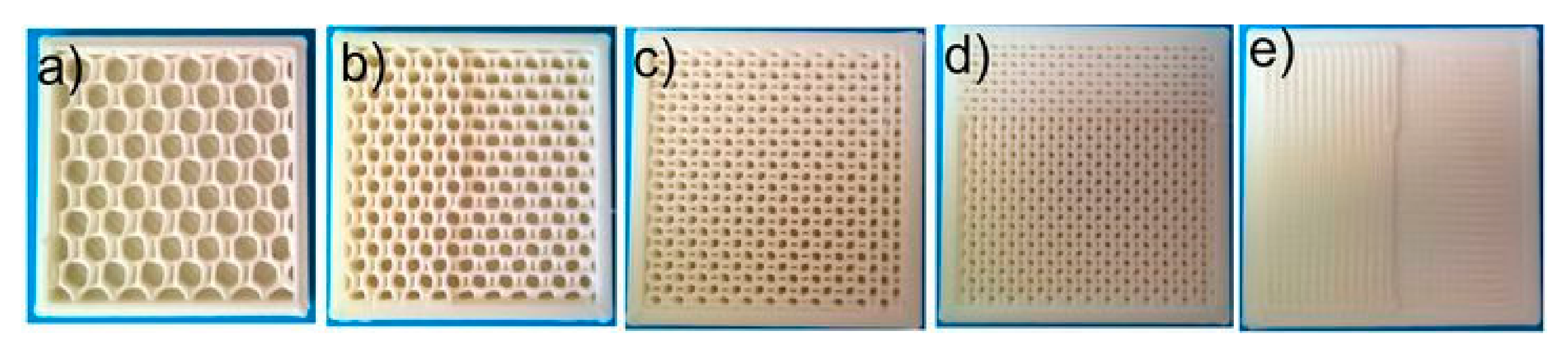
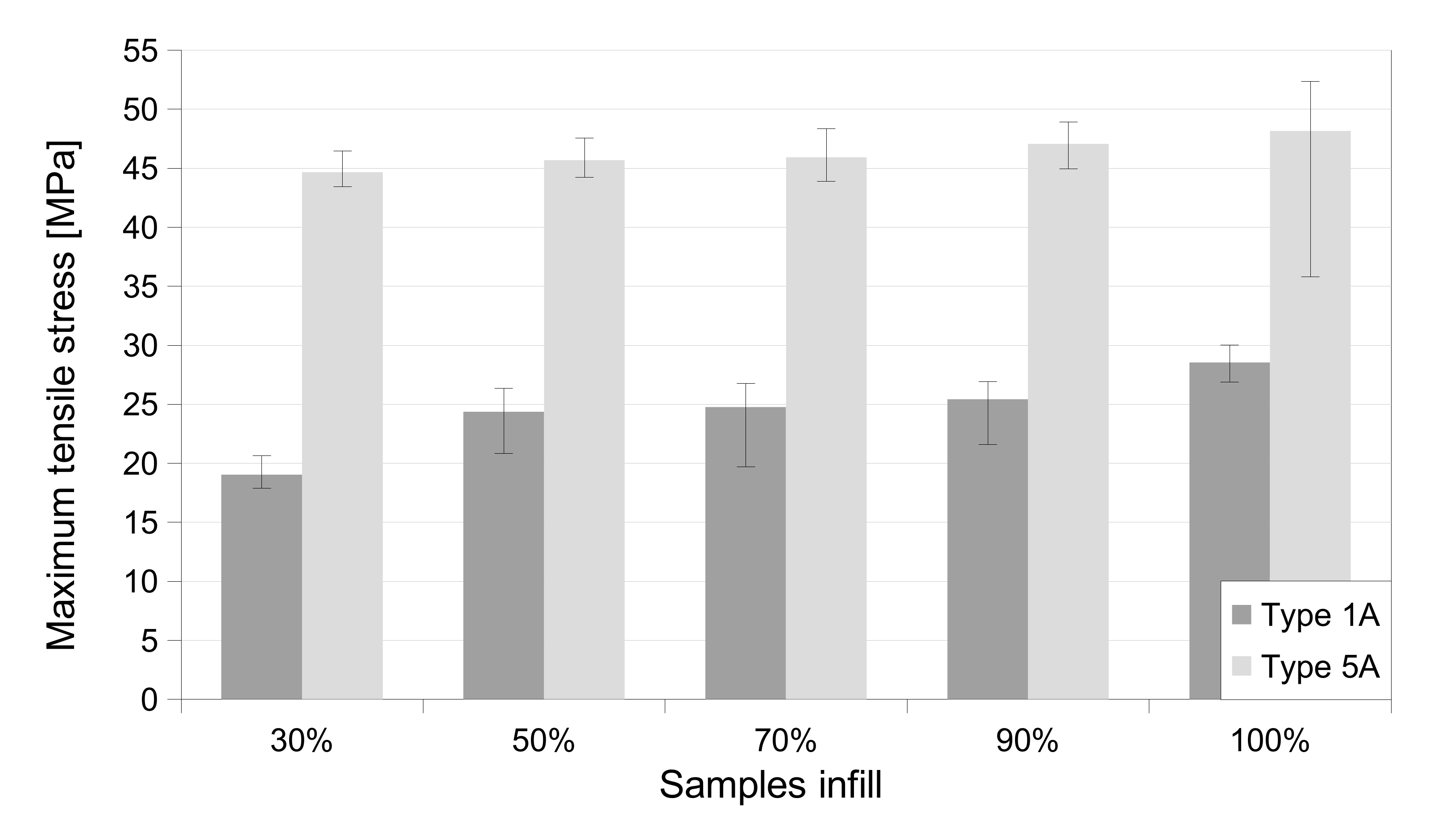
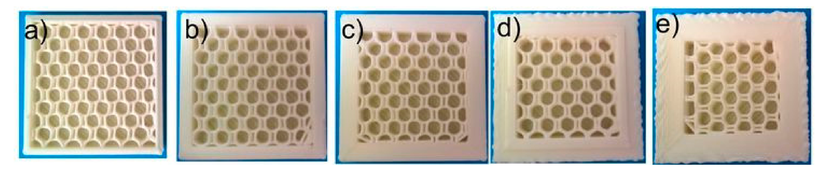
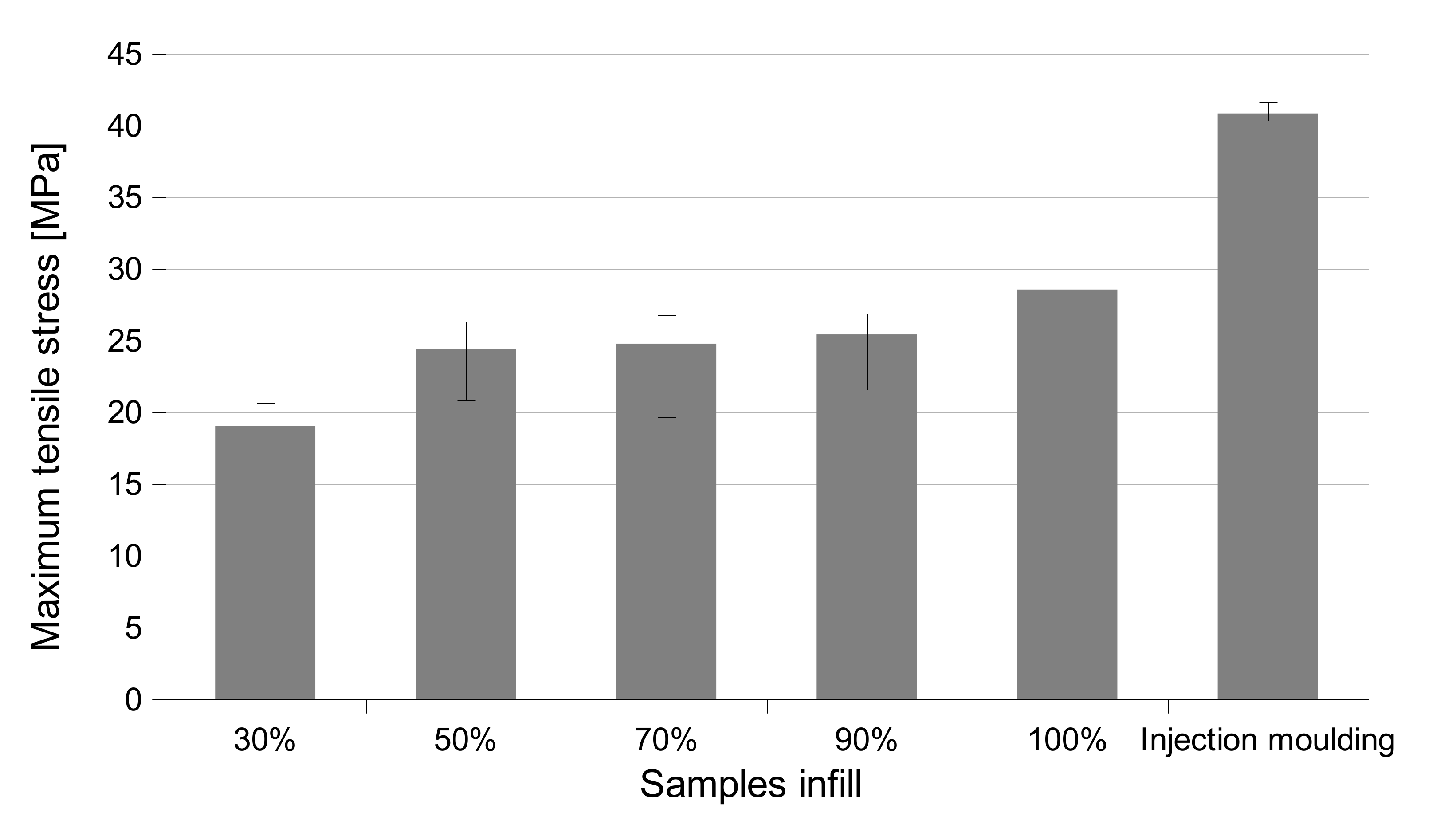
The density of the infill has little effect on the strength of the element. Increasing the infill density improves the strength, but not so much: it is suggested to use 90% infill density.
-
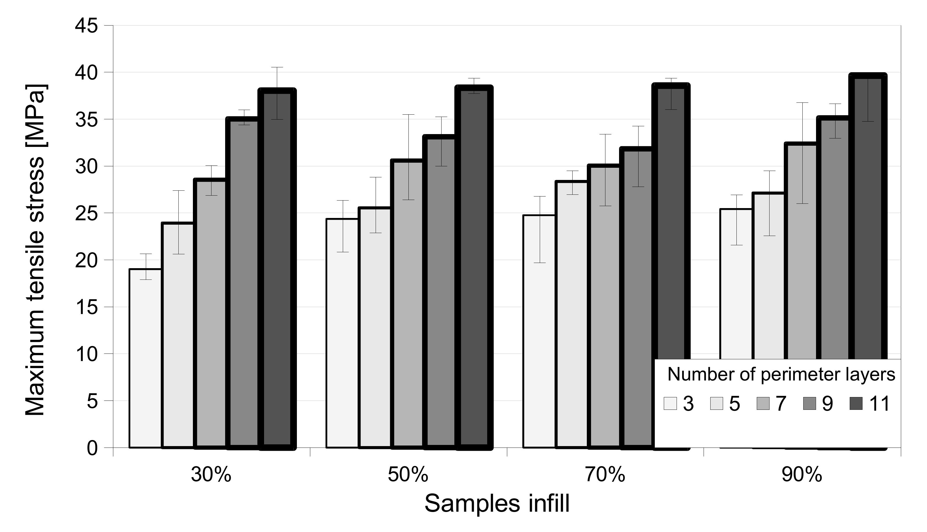
The number of contour layers significantly influences the strength, and increasing them directly leads to an increase in mechanical strength. However, this parameter has its limits, and we must distinguish the cross-section geometry of the samples printed with 100% infill from those printed without the infill. The travel path of the printing nozzle was similar to that of the contour layers in the first example, and in the other example, layers were printed from lines parallel to the Y and X axes.
-
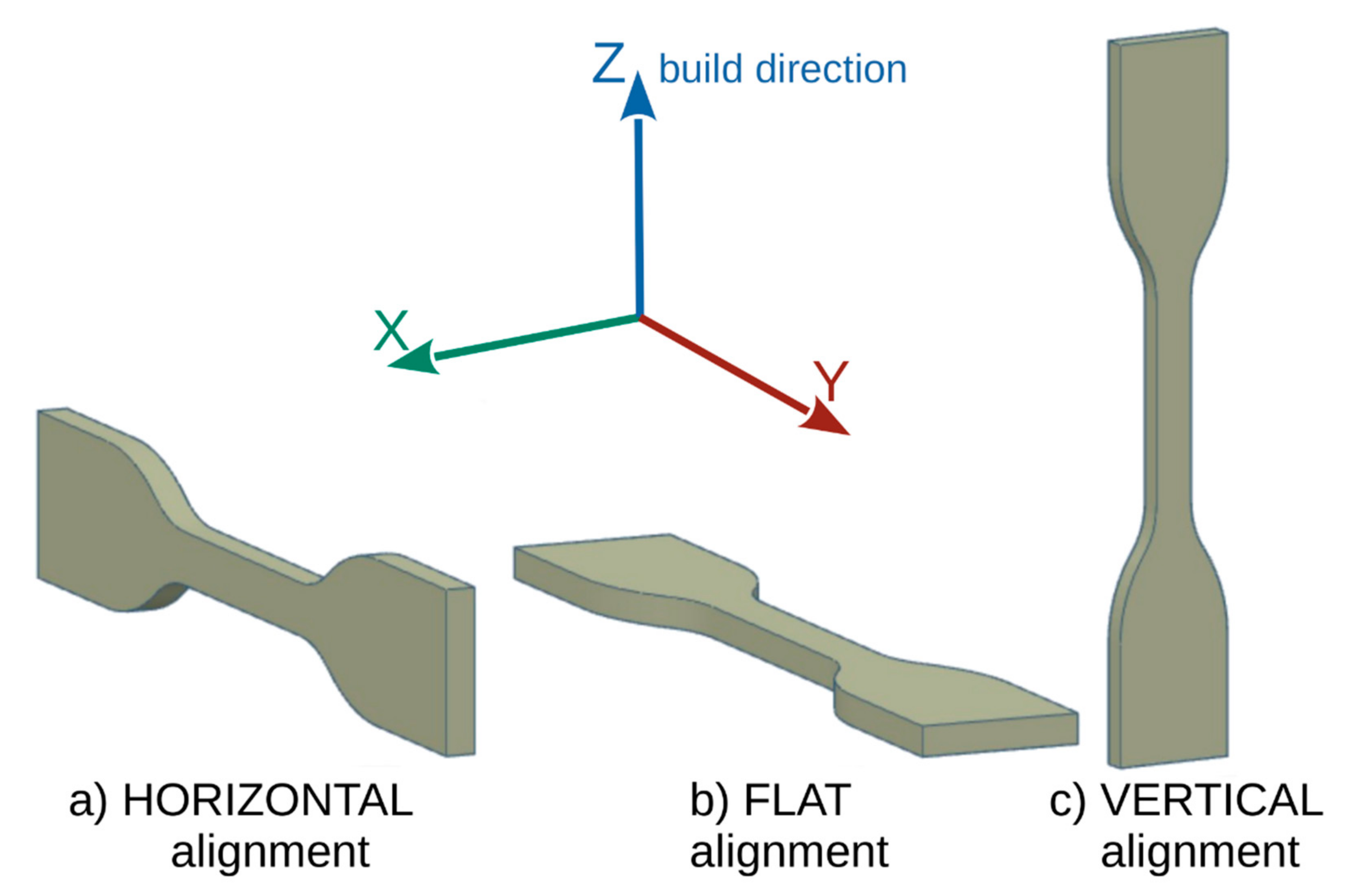
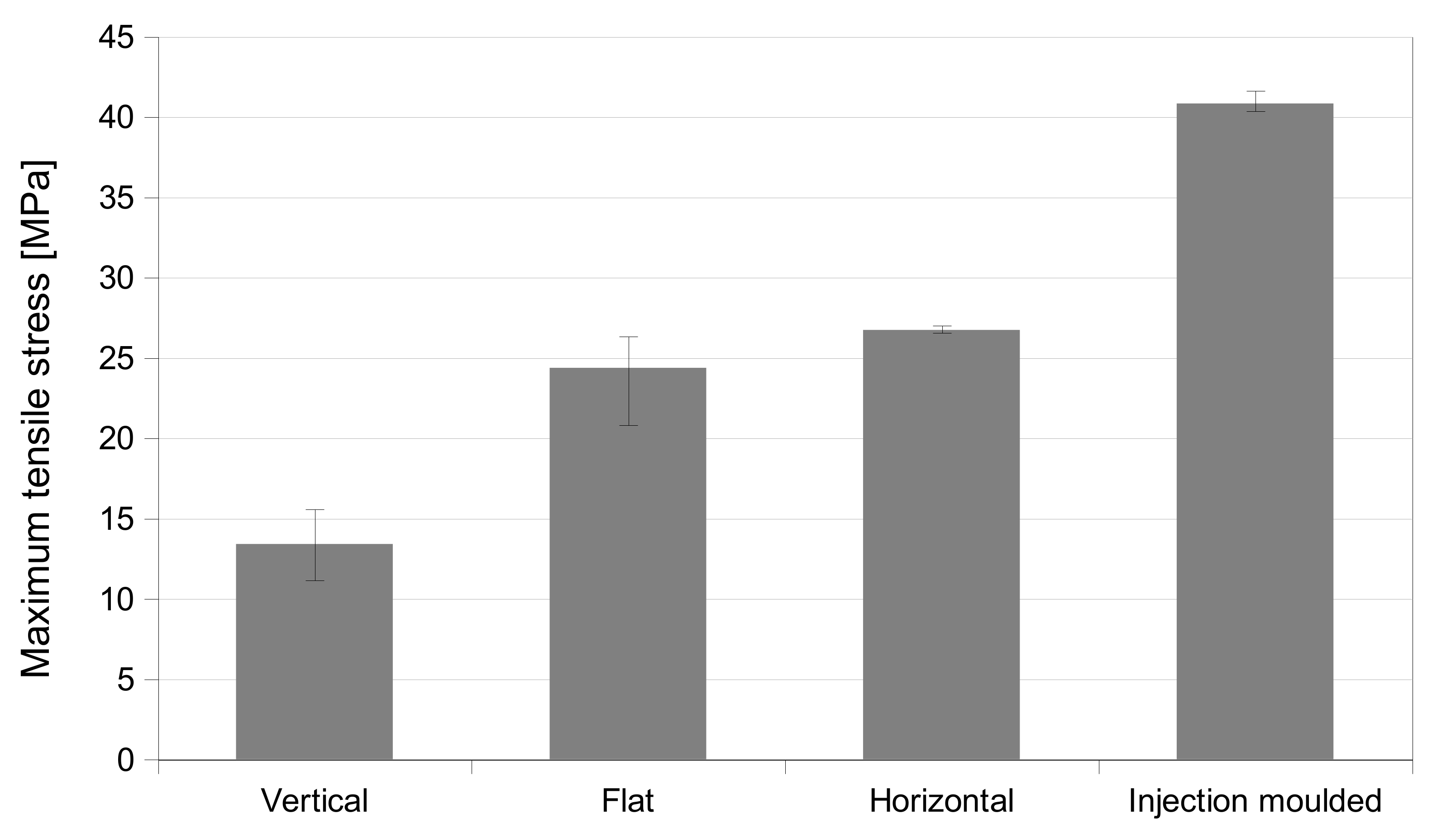
The arrangement of the element on the table is of great importance as it influences the strength in a specific direction. The weakest parts were printed in the Z-axis orientation (vertical). It is best to print samples horizontally, most often printing in a flat orientation. The direction of forces causing the highest stresses must always be considered when designing elements and placing the design on the printer table for printing.
-
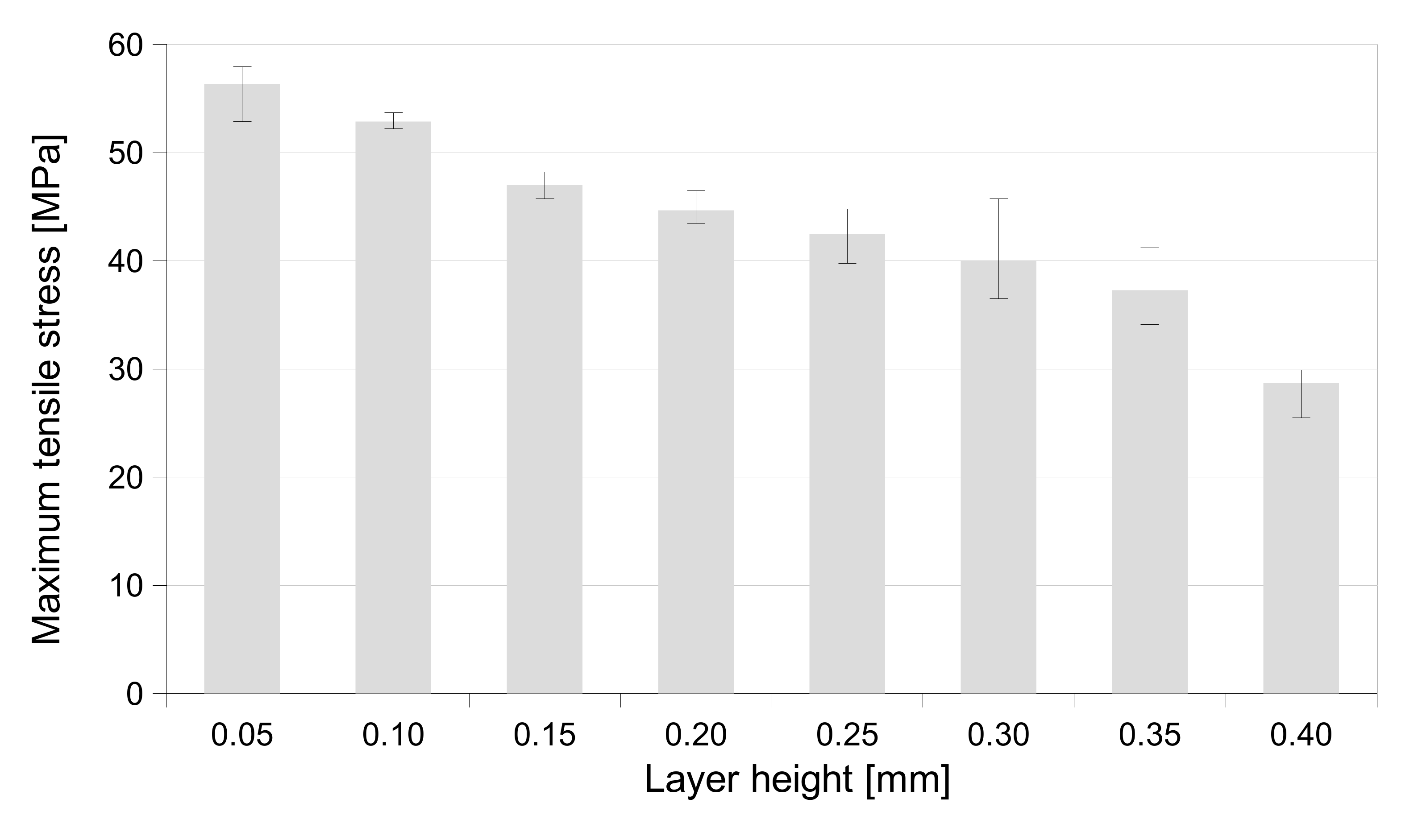
The height of the layer in the Z-axis determines its strength. The low height of the layer produces very durable parts. However, they influence the economic factor of printing time.
In further research, it will be necessary to determine the influence of different geometries of cross sections on the FDM printed parts. The obtained results will be used in the near future to compare ABS composites filled with graphene and carbon nanotubes.

Author Contributions

Conceptualization, A.S. and M.S.; methodology, B.P., A.S. and W.R.; validation, A.S. and M.S.; formal analysis, B.P., W.R. and A.S.; investigation, W.R. and A.S.; resources, A.S. and M.S.; writing—original draft preparation, B.P. and W.R.; writing—review and editing, M.S.; visualization, W.R. and M.S.; supervision, A.S. and M.S.; project administration, M.S.; funding acquisition, M.S. All authors have read and agreed to the published version of the manuscript.

Funding

This research was funded by Foundation for Polish Science (project nr First TEAM/2016-1/7).

Data Availability Statement

Data available on request from the corresponding author.

Acknowledgments

This research was supported by the Institute of Metrology and Biomedical Engineering (Faculty of Mechatronics at the Warsaw University of Technology).

Conflicts of Interest

The authors declare no conflict of interest. The funders had no role in the design of the study; in the collection, analyses, or interpretation of data; in the writing of the manuscript, or in the decision to publish the results.

References

  1. Sauer, M.J. Evaluation of the Mechanical Properties of 3D Printed Carbon Fiber Composites; South Dakota State University: Brookings, SD, USA, 2018; Available online: https://openprairie.sdstate.edu/etd/2436 (accessed on 1 June 2021).
  2. Bagsik, A.; Schöppner, V. Mechanical properties of fused deposition modeling parts manufactured with ULTEM*9085. In Proceedings of the 69th Annual Technical Conference of the Society of Plastics Engineers, Boston, MA, USA, 1–5 May 2011; pp. 1–5. [Google Scholar]
  3. Afrose, M.F.; Masood, S.H.; Iovenitti, P.; Nikzad, M.; Sbarski, I. Effects of part build orientations on fatigue behaviour of FDM-processed PLA material. Prog. Addit. Manuf. 2016, 1, 21–28. [Google Scholar] [CrossRef]
  4. Uddin, M.S.; Sidek, M.F.R.; Faizal, M.A.; Ghomashchi, R.; Pramanik, A. Evaluating mechanical properties and failure mechanisms of fused deposition modeling acrylonitrile butadiene styrene parts. J. Manuf. Sci. Eng. 2017, 139, 081018. [Google Scholar] [CrossRef]
  5. Syamsuzzaman, M.; Mardi, N.A.; Fadzil, M.; Farazila, Y. Investigation of layer thickness effect on the performance of low-cost and commercial fused deposition modelling printers. Mater. Res. Innov. 2014, 18, S6-485–S6-489. [Google Scholar] [CrossRef]
  6. Johansson, F. Optimizing Fused Filament Fabrication 3D Printing for Durability: Tensile Properties and Layer Bonding; Blekinge Institute of Technology: Karskruna, Sweden, 2016; Available online: https://www.diva-portal.org/smash/get/diva2:940935/FULLTEXT02.pdf (accessed on 1 June 2021).
  7. Kiński, W.; Pietkiewicz, P.; Nalepa, K.; Miąskowski, W. Tensile strength comparison of composite specimens printed in FDM technology with specimens printed from PLA. Mechanik 2017, 90, 615–617. [Google Scholar] [CrossRef] [Green Version]
  8. Chacón, J.M.; Caminero, M.A.; García-Plaza, E.; Núnez, P.J. Additive manufacturing of PLA structures using fused deposition modelling: Effect of process parameters on mechanical properties and their optimal selection. Mater. Des. 2017, 124, 143–157. [Google Scholar] [CrossRef]
  9. Rybachuk, M.; Mauger, C.A.; Fiedler, T.; Öchsner, A. Anisotropic mechanical properties of fused deposition modeled parts fabricated by using acrylonitrile butadiene styrene polymer. J. Polym. Eng. 2017, 37, 699–706. [Google Scholar] [CrossRef]
  10. Dawoud, M.; Taha, I.; Ebeid, S.J. Mechanical behaviour of ABS: An experimental study using FDM and injection moulding techniques. J. Manuf. Process. 2016, 21, 39–45. [Google Scholar] [CrossRef]
  11. Upadhyay, K.; Dwivedi, R.; Singh, A.K. Determination and comparison of the anisotropic strengths of fused deposition modeling P400 ABS. In Advances in 3D Printing & Additive Manufacturing Technologies; Wimpenny, D.I., Pandey, P.M., Kumar, L.J., Eds.; Springer: Singapore, 2017; pp. 9–28. [Google Scholar] [CrossRef]
  12. Wu, W.; Geng, P.; Li, G.; Zhao, D.; Zhang, H.; Zhao, J. Influence of layer thickness and raster angle on the mechanical properties of 3D-printed PEEK and a comparative mechanical study between PEEK and ABS. Materials 2015, 8, 5834–5846. [Google Scholar] [CrossRef] [PubMed]
  13. Tanoto, Y.Y.; Anggono, J.; Budiman, W.; Philbert, K.V. Strength and Dimension Accuracy in Fused Deposition Modeling: A Comparative Study on Parts Making Using ABS and PLA Polymers. Rekayasa Mesin 2020, 11, 69–76. [Google Scholar] [CrossRef]
  14. Górski, F.; Wichniarek, R.; Kuczko, W.; Zawadzki, P.; Buń, P. Strength of ABS parts produced by Fused Deposition Modelling technology–a critical orientation problem. Adv. Sci. Technol. Res. J. 2015, 9, 12–19. [Google Scholar] [CrossRef] [Green Version]
  15. Hossain, M.S.; Ramos, J.; Espalin, D.; Perez, M.; Wicker, R. Improving tensile mechanical properties of FDM-manufactured specimens via modifying build parameters. In Proceedings of the International Solid Freeform Fabrication Symposium: An Additive Manufacturing Conference, Austin, TX, USA, 12 August 2013; Volume 2013, pp. 380–392. [Google Scholar]
  16. Sheth, S.; Taylor, R.M.; Adluru, H. Numerical investigation of stiffness properties of FDM parts as a function of raster orientation. In Proceedings of the Solid Freeform Fabrication Symposium: An Additive Manufacturing Conference, Austin, TX, USA, 7–9 August 2017; pp. 1112–1120. [Google Scholar]
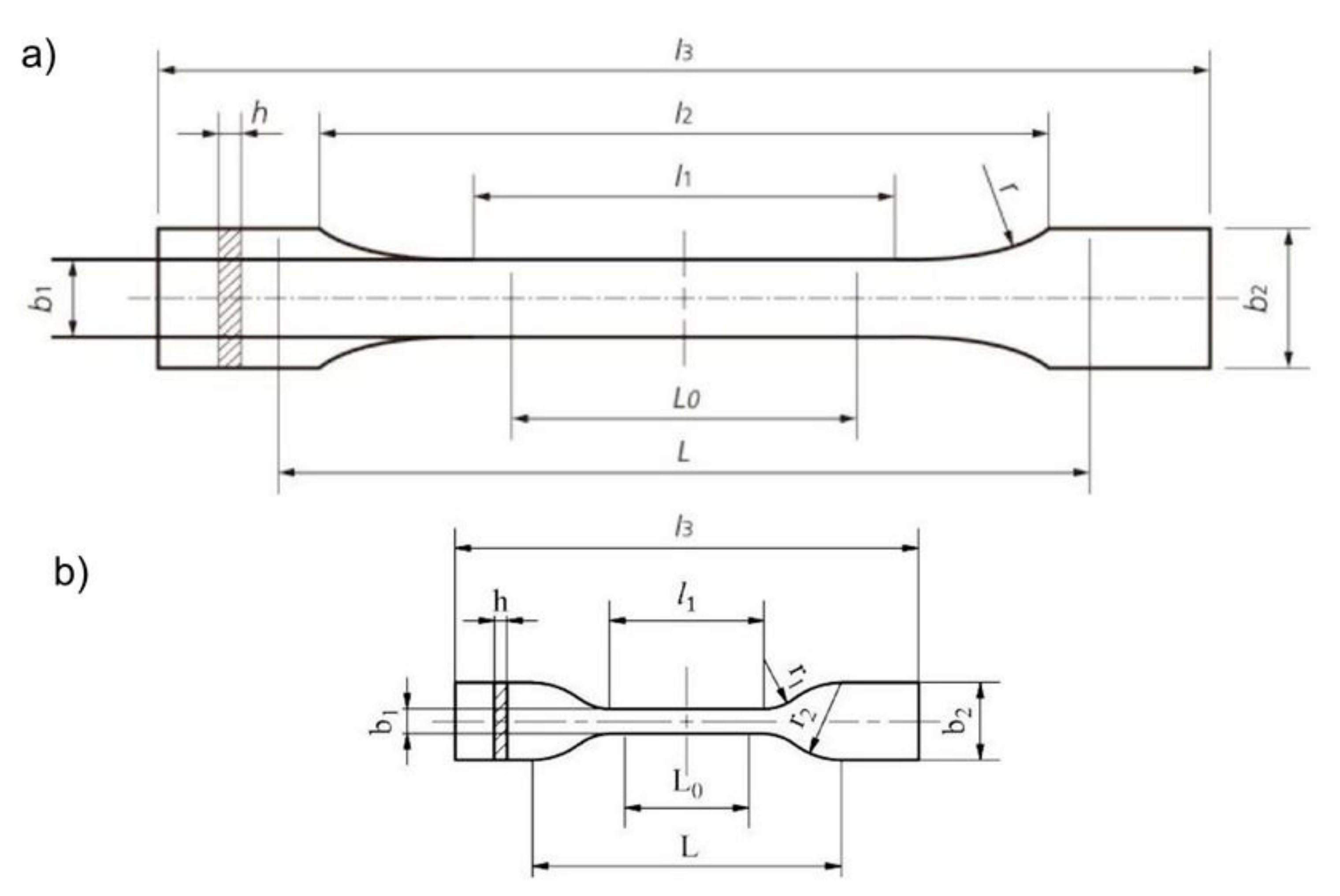
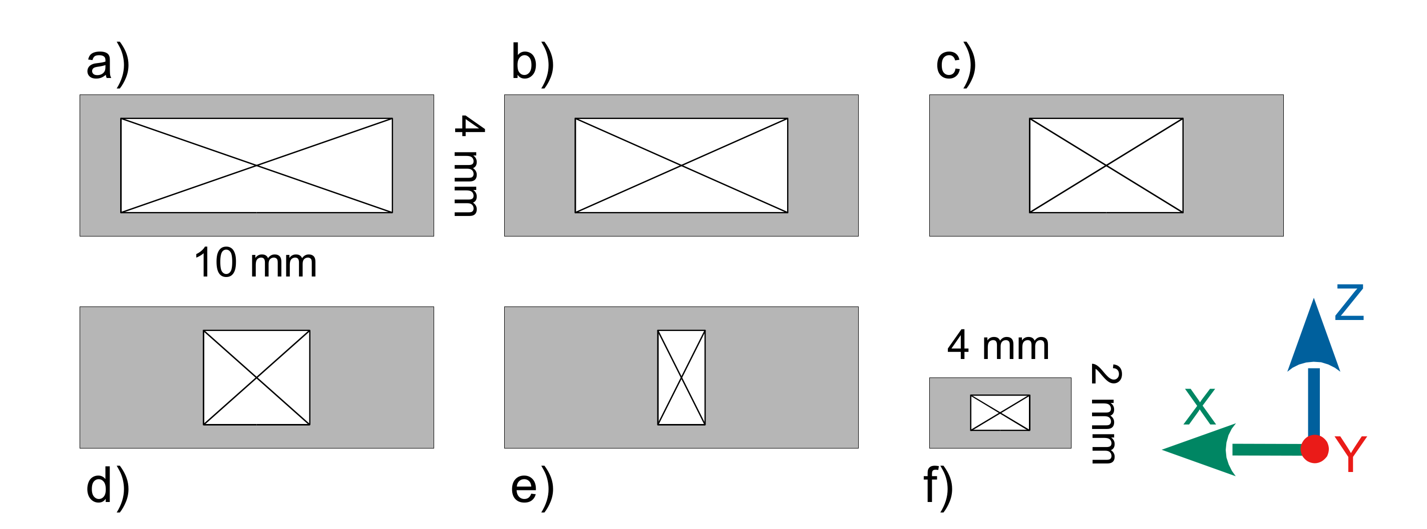
Figure 1. Universal dog bone samples used for tensile strength tests: (a) type A1, (b) type 5A.
Applsci 11 06946 g001
Figure 2. Photographs of printed samples with various densities of infill: (a) 30%, (b) 50%, (c) 70%, (d) 90%, (e) 100%.
Applsci 11 06946 g002
Figure 3. Photographs of printed samples showing the difference in the number of contour layers: (a) 3, (b) 5, (c) 7, (d) 9, (e) 11, with the same value of infill, 50%.
Applsci 11 06946 g003
Figure 4. Orientation of the samples on the worktable: (a) “horizontal”, (b) “flat”, (c) “vertical”.
Applsci 11 06946 g004
Figure 5. Cross sections of samples: (a) type 1A, 3 layers of contour, (b) type 1A, 5 layers of contour, (c) type 1A, 7 layers of contour, (d) type 1A, 9 layers of contour, (e) type 1A, 11 layers of contour, (f) type 5A, 3 layers of contour.
Applsci 11 06946 g005
Figure 6. The influence of the orientation of printing on the mechanical properties of the samples.
Applsci 11 06946 g006
Figure 7. The influence of the infill density of printed samples on their mechanical properties.
Applsci 11 06946 g007
Figure 8. The influence of the number of perimeter layers shows a corresponding change in the overall density of the mechanical properties of the printed dog-bone shaped samples.
Applsci 11 06946 g008
Figure 9. The influence of the sample type and infill density on the mechanical properties of the printed samples.
Applsci 11 06946 g009
Figure 10. The influence of the layer thickness applied during the printing process on the mechanical properties of the printed samples.
Applsci 11 06946 g010
Table 1. Detailed dimensions of the samples.
Parameter NameType 1AType 5A
l3–overall length≥150 mm≥75 mm
l2-parallel length105 mm-
l1– narrow section length80.0 ± 0.2 mm25.0 ± 1 mm
r-radius60 mm-
r1-radius-8.0 ± 0.5 mm
r2-radius-12.5 ± 1 mm
b2–grips width20.0 ± 0.2 mm12.5 ± 1 mm
b1–gauge width10.0 ± 0.2 mm4.0 ± 0.1 mm
h-thickness4.0 ± 0.2 mm2.0 ± 0.2 mm
L0–gauge length50.0 ± 0.2 mm20.0 ± 0.5 mm
L–distance between grips115.0 ± 1 mm50.0 ± 2 mm
Table 2. Results of the tensile tests for the samples printed with different orientation and injection molded reference samples.
(FDM)
Vertical
(FDM)
Flat
(FDM)
Horizontal
Injection Molded
Tensile strength [MPa]13.3924.3626.7340.82
In relation to injection molding33%60%65%-
Table 3. Tensile stress results depending on the infill density of printed samples.
30%50%70%90%100%Injection Molded
Tensile strength [MPa]19.0124.2624.7625.4128.3540.82
In relation to injection molding47%59%61%62%69%-
In relation to 100% infill density67%86%87%90%--
Table 4. Results of the mechanical tests of the samples printed with different numbers of perimeter layers and different infill density.
Number of
Perimeter Layers
FDM 30%FDM 50%FDM 90%
3Tensile strength [MPa]19.0124.3625.41
In relation to injection molding47%60%62%
5Tensile strength [MPa]24.6125.5331.69
In relation to injection molding60%63%78%
7Tensile strength [MPa]28.5430.5832.38
In relation to injection molding70%74%79%
9Tensile strength [MPa]33.1235.0235.12
In relation to injection molding81%86%86%
11Tensile strength [MPa]38.0338.3439.63
In relation to injection molding93%94%97%
Publisher’s Note: MDPI stays neutral with regard to jurisdictional claims in published maps and institutional affiliations.

