1. Introduction
1.1. The State-of-the-Art
Kumru and Kumru [
1] stated that the production system performance usually depends on the chosen types of machine tools used by companies. The overall production system performance can be adversely affected by incorrectly chosen machine tools. Zhang et al. [
2], in their research, pointed out the fact that large-scale measurement systems are widely used in industrial measurement fields such as robot performance evaluation, ship building, aerospace assembling, railway facility collimation and calibration, automobile quality inspection, numerical control machine calibration, reverse engineering and so on. The rapid progress observed today in the field of engineering design includes the growing need to incorporate shapes of complex geometry into design, as Skalski et al. [
3] explained.
A constant development of computer numerical control (CNC) production machines and their operating systems enables the production of complex machine parts with high measurement and shape accuracy, as Adams [
4] explained. Wdowik et al. [
5] mentioned that the challenges of today’s competitive environment are the result of new development in the construction of CNC machine tools and coordinate measuring machines (CMMs). Nekrasov and Tempel [
6] reported that the creation and usage of flexible production modules and production complexes for material processing by cutting leads to the acquisition and widespread usage of CNC machines. Swornowski [
7], in his research, presented the application of neural networks in determining and correcting the deformation of a coordinate measuring machine workspace. Gaska et al. [
8] stated that as production accuracy increases, the measurements and methods used to assess the measurement uncertainty need to be more accurate.
The coordinate measuring machine means “any measuring machine that records information from the work piece step-by-step using optical or tactile means on the basis of a coordinate system defined by the device and further processes the coordinate values using a computer”, as stated Cuesta et al. [
9]. As it was presented in Quality Magazine Editorial [
10], CMMs can measure parts regardless of their distorted condition. This provides immediate variable data that quantify how badly and in what manner parts are distorted so that process corrections can be made immediately if necessary. Compared to other types of measurement, it is the ability to correctly and quickly capture and evaluate the obtained data ranks coordinate measuring machines among the top measuring technology with perfectly sophisticated tactile or non-contact scanning systems, such as Schmalzried and Schmitz [
11] explained.
Equipping of coordinate measuring machines with powerful control and processing computers predetermines them as a practical solution suitable for checking the complex geometry of the produced component base, as stated by Schneider et al. [
12]. Waurzyniak [
13] performed research about off-line programming LK’s Camio Studio CMM programming software and he found out that off-line programming software tools for CMMs allow producers to increase measurement capacity and throughput by programming CMMs, probes, and fixtures before parts are made. Krawczyk et al. [
14] presented the fact that evaluating the accuracy of coordinate measurement is a very complex task, and especially the development of one method for all coordinate measuring systems. Most methods focus only on coordinate measuring machines. Research work from Hussien [
15] presented a computer-aided inspection system that reads as input a fixed B-rep model in SAT format and produces the final CMM program in DMIS format. In research by Gaska et al. [
16] they tried to present the direction of further research, but the discussion focused mainly on five-axis systems using touch-trigger probes. Models for these systems would be the basis for a bigger problem, a virtual machine for five-axis scan measurements. There is no satisfactory solution for this problem even with typical three-axis CMMs. Neamtu et al. [
17] reported that, currently, most 3D measuring software offers functions for off-line coordinate measuring machine (CMM) programming. Several software solutions allow the simulation of CMM and other elements involved in the measurement process, such as a human operator or an automated system for loading and unloading the measured parts. In research by Qu et al. [
18], a new approach to measurement methodology for a vision integrated coordinate measuring system was developed and demonstrated. The vision coordinate measurement system features the integrated use of a high-precision coordinate measuring machine (CMM), a vision system, advanced computing software and related electronics. It has potential usage across a range of producing issues with a big impact on metrology, control and reverse engineering. Lin et al. [
19] presented the view that fast and accurate measurement in the process has recently become standard in product cycles, especially in the production of parts having 3D contoured shapes. As a result, the ability to analyse large amounts of dimensional data requires that today’s coordinate measuring machines (CMMs) take advantage of their extreme functionality. Lotze [
20] and Vermeulen et al. [
21] defined Coordinate Measuring Machines (CMMs) in a very similar way, as the universal machines that are often used to measure geometrical dimensions and shapes of rather complex products in production. Cheng et al. [
22] pointed out that measuring instruments should be intelligent, accurate, and multifunctional and evolve in a multidirectional, scientific and proportionate manner; reliable evaluation of the measurement uncertainty of precision instruments is also becoming increasingly difficult, and the measurement uncertainty of coordinate measuring machines (CMMs) is one of the typical problems.
The study performed by Suzuki et al. [
23] proposes a method for quick production of the deformed evaluation image using a whole-space tabulation method. Another study conducted by Shiou and Chen [
24] represents the development of a hybrid measuring system integrated into a machining centre to perform a possible intermittent measurement of the work piece. The work conducted by Sladek [
25] mainly focuses on the issue of measuring tip contact with the measured object, and it is based on the author’s original method for the identification of a probing system: contact probe errors with the use of a circular standard together with the system of software separation of components. Gaska et al. [
26] stated that coordinate measuring machines are today a necessary tool of quality management systems, as they allow quick verification of the conformity of the object with the geometric specifications contained in the technical documentation.
Since coordinate measuring machines are a part of every modern production plant, the paper is a response to the current situation, and its development required not only knowledge of the coordinate measuring machine and related software, but also the knowledge of mechanical metrology, computer technology, reading and drawing preparation, documentation and parametric modelling in the CAD (computer-aided design) system.
1.2. Problem Description
The measuring program is created in the measuring and evaluating software PC-DMIS (PC-Dimensional Measurement Interface Specification), which is based on the analysis of the measured part and the prepared measuring procedure, which was pointed out by Jing [
27]. Theoretical and practical skills are used, regarding not only the coordinate measuring device itself but also from the area of engineering metrology, reading and preparation of technical documentation, and ultimately, skills from the area of parametric modelling in the CAD system CATIA. Correctness of the prepared measuring program is verified in the PC-DMIS work environment by an off-line simulation, which gives prerequisites for its non-problematic verification and the measuring itself on the coordinate measuring machine DEA Global Performance 12.22.10.
Compared to basic construction elements of the coordinate measuring device, its measuring and evaluating software becomes equally important, which also participates on a large scale of all measuring activities administered. By measuring and evaluating software of the coordinate measuring device DEA Global Performance, the PC-DMIS CAD++ v4.3 is built based on additional program packages, which can be bought by each user according to their needs. The stated software represents the highest available version of the PC-DMIS, by which it is predestined to perform the most challenging applications for scanning and touch measuring. The default work environment consists of a graphic window, a command tree for a coordinate measuring device and several panels with “tools” used for creation of the measuring program particle. The principle of work in the work environment is similar, compared to other applications installed in the Windows OS (Operating System).
PC-DMIS CAD++ v4.3 (hereinafter only PC-DMIS) as a measuring software of the coordinate measuring device offers many various available functions, out of which at least these basic ones need to be mentioned:
Defining a new scanning system and its calibration.
Programming of a measured task.
Using the data file obtained by measuring.
Logging of measurement results.
It is necessary to state that the following subchapters do not explain the basic principles of calibration and measuring on the coordinates measuring devices but point to the most important options of the measuring software PC-DMIS. During the development of a new measuring program, the first step is choosing a suitable touch scanning system, which can be done by:
Defining a new configuration of elements of the touch scanning system, when the individual elements are taken out of the database in such a sequence so that the scanning system is created in the measuring program as identical with the scanning system attached in the endpoint of the coordinate measuring machine’s tailstock,
Invoking an existing touch scanning system in the case in which we have already used a scanning system with the required combination of elements in the past.
Every new configuration of the scanning system elements always has one pre-defined orientation A = 0°, B = 0°, and in the case in which any other system orientation is necessary for its measuring, it is necessary to define it. After the creation of a new touch scanning system, its calibration follows in all necessary directions, during which the point of touch of the scanning system comes into contact with the surface of a very accurate calibration ball. The diameter and position of the calibration ball in the work environment of the device are defined in the PC-DMIS in the calibration tools list.
PC-DMIS differentiates several regimes of calibration, derived from the following basic regimes:
As the measuring program includes a command file, based on which the device performs a particular measuring task, under the phrase “programming of the measuring task” we mean all activities leading to the creation of a functional measuring program of the controlled part. Nowadays, construction and technological preparation of the production is carried out by use of the software packages CAD/CAM (computer-aided manufacturing) like NX, Creo Parametric, CATIA, etc. Pro. Therefore, a great advantage of the PC-DMIS software is its ability to import a prepared parametric model of the measured part in the CAD system, which can be used for the programming of the measuring task, as well as for the presentation of the measured results. Measuring programs for the coordinate measuring device DEA can be created in the programming environment of the PC-DMIS by two means:
On-line programming—During the on-line programming of the measuring task, the computer with the installed measuring and evaluating software PC-DMIS is directly connected with the coordinate measuring device. A so-called learning creates the measuring program, when the user with the help of a manual operation unit estimates entry-measuring points on the surface of the controlled part, necessary for the identification of the position and type of the scanned geometric element. For the required accuracy of the measurement to be the highest, the device then repeats the strategy learnt in an automatic cycle and scans at least those same points, defined by the user. An indispensable condition for programming of the measuring task on-line is the presence of the controlled part in the work environment of the device, whereas its imported parametric model can be used as well, depending on the need. In the case of use of the imported parametric model, programming of the measuring task is carried out in a way so that the operator clicks on the required place on the surface of the parametric model in the programming environment of the PC-DMIS. The coordinates measuring device will realize the given task by scanning the point on the surface of the real part in the same place the operator required. Considering that during the programming it is not possible to administer any other measuring activities on the device, the disadvantage of measuring programs created in this way has mainly economic importance, particularly when the measuring device represents large purchase costs.
Off-line programming—The creation of the measuring program takes its course on a remote computer with an installed measuring software PC-DMIS off-line, which is not directly connected with the coordinate measuring device. Programming of the measuring task always stems from the imported parametric model of the measured part. Individual points needed for identification of the position and type of the geometric unit are entered by clicking on the surface of the imported model, whereas the value of the dimension of each geometric element represents a nominal value of the dimension of the same element on the real part. A program created off-line can be simulated in the programming environment of the PC-DMIS, which provides an option to remove the created collision of the scanning system with the measured part (
Figure 2).
A considerable advantage of the off-line programming of the measuring task is the removal of auxiliary unproductive times of the device that originate in programs created directly on the coordinate measuring device.
The next chapter will describe the procedure of component measurements with emphasis on compliance with the accuracy of measurement procedures.
2. Materials and Methods
PC-DMIS as a measuring and evaluating software of the coordinates measuring device uses a data file acquired by measuring for calculation of parameters (distance, shape deviation, position, rotational accuracy, etc.) describing production accuracy of the measured part. With this, it is possible to stem directly from the measured geometric elements and designed geometric elements, which the user can construct according to their needs. PC-DMIS also enables exporting the data file acquired by measuring into formats supported by leading CAD/CAM systems, which is applied mainly in the area of reverse engineering, when the curves are transferred with the file of measured points with a goal to reversely create a parametric model of the measured part.
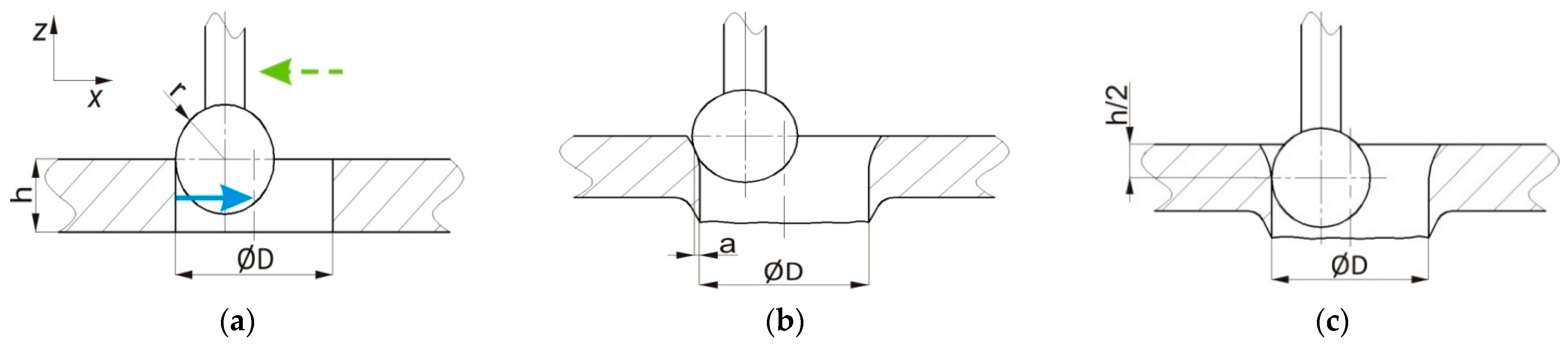
The basic principle of the coordinate measuring arises from the assumption that “every machine part consists of various geometric elements, such as plane, cone, cylinder, ball, torus”. These elements are scanned on the coordinates measuring device in the coordinate system, whereas the position of each one of the elements is distinct in this system and the goal is to estimate a shape deviation (circularity) on the coordinates measuring device by touch measuring. It originates by a cross section of the plane α on a real cone, which means that the given deviation will be investigated within the height of the cone equal to the value x (
Figure 3a). To determine the circularity of the investigated circle by touch measuring, we will scan four points evenly placed around its perimeter (
Figure 3b). Measuring software will transfer a substitute geometric element with the scanned points and consequently, by its evaluation, the expected shape deviation of the appropriate circle will be acquired.
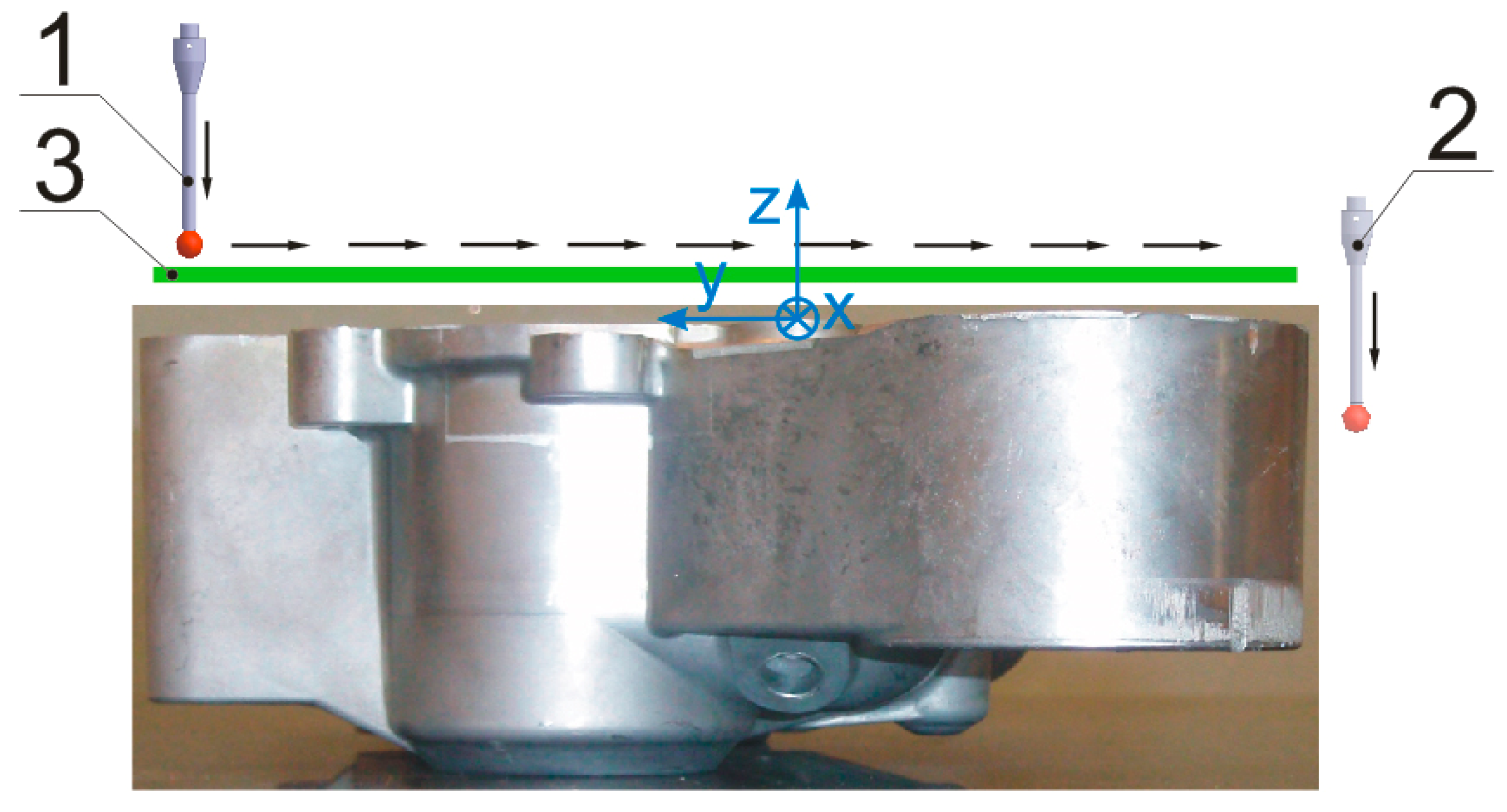
It is necessary to measure the position of the point A placed on the plane φ by use of the coordinate measuring device and touch, the point of which is a ball with radius r = 1 mm. In the first case (
Figure 4a), the point A is scanned so that the scanning system moves on the trajectory that is parallel with the axis x of the coordinate measuring device. Looking at that trajectory, on which the scanning system moves, it contains an angle β = 30° with the normal of the plane φ, the result of measuring is influenced by a gross error and the position of the point determined by measuring will be moved by the value a, compared to the set position. In the second case (
Figure 4b), the point A is scanned so that the scanning system moves on the trajectory that is parallel with the normal of the plane φ. As it results from the above stated text, the result of measuring will not be influenced by the gross error and the position of the point determined by measuring will respond to its set position.
For an easier problem explanation, we will use a case of touch measuring of a cylindrical opening diameter of a moulded panel, the semi product of which is a plate with the thickness h = 1 mm. The measured cylindrical opening is made by perforation. A considerable parameter is the setting of correct depth of scanning hs, in this case equal to zero, which means that the horizontal axis of the point (ball with radius r = 2 mm) of the touch is equal to the plane of the moulded panel surface. We consider two cases during measuring:
In the first case (
Figure 5a), an ideal cylindrical opening is made, without deformation, the result of which is scanning of points placed on the real diameter of the measured opening.
In the second case (
Figure 5b), the opening is made with a deformation, which causes the scanned points to not be situated on the real diameter of the scanned opening, but their position is moved by the value a.
We will reach the correct result of the given measuring by setting a suitable depth of scanning (
Figure 5c) that is in this case equal to half thickness of the material. It means that the scanning system will move in the direction of the axis until the horizontal axis of the touch point is not under the plane of the moulded panel surface. From the stated results, the set depth of scanning is h
s = mm.
We have expressively defined the position of the measured part in the work environment of the coordinates measuring device by removing degrees of freedom. Principle of levelling “3–2–1” is in
Figure 6.
3. Results
A measuring program was created by use of the imported parametric model of the component, from which a directional vector of the plane, on which the particular point has been scanned, is deducted for each scanned point. Coordinates of the position of individual scanned points are up to the moment of levelling deducted in the coordinate system of the device, and after levelling, these are in the coordinate system of the part. Nominal values of observed geometric specifications are deducted by use of the imported parametric model from this model; therefore, the parametric model of the measured part finds its justification even in the stage of logging of the measured results. Position and orientation of axes +x, +y, +z of the coordinate system of the part after fine levelling are in
Figure 7.
In the programming of the measured task with the usage of a parametric model of the measured part, the first step is the import of this model into the prepared measuring program. Convertor PC-DMIS transforms the output data of the CAD system into a format supported by the particular measuring and evaluating software. Prior to levelling, the position of the measured part in the work environment is unknown, from which stems an incorrect display of the scanning system considering the position of the measured part (
Figure 8a). We can estimate by necessary adjustment of the display setting which axis of the imported parametric model represents the axis of the coordinate measuring machine pertaining to it (
Figure 8b). Considering the placement of the measured part in the work environment of the coordinates measuring device, the display settings are as follows:
Axis +x on the parametric model corresponds to the axis +y on the device,
Axis +y on the parametric model corresponds to the axis +x on the device,
Axis +z on the parametric model corresponds to the axis +z on the device.
Considering the analysis of the measured part, for fine levelling (
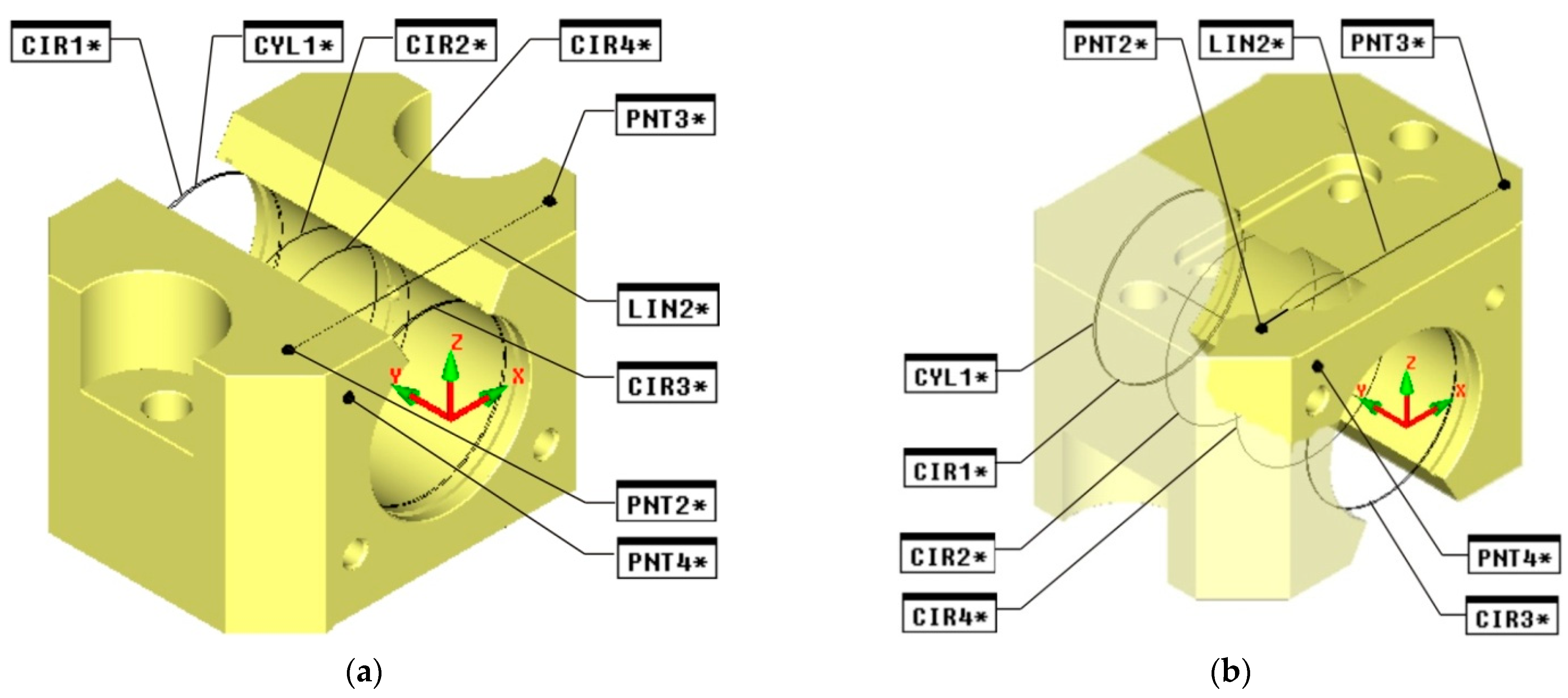
Figure 9) it is necessary to scan the opening Ø32 H7 (CYL1), the line (LIN2) and the point (PNT4).
Figure 9 does not show elements of the gross levelling for a more distinct clarity. The opening Ø32 H7 (mm) will be scanned by four circles CIR1, CIR2, CIR3, CIR4 in four cuts, by which the designed geometric element will be transferred, cylinder CYL1. Every circle will be scanned in the appropriate cut by eight points, and the selected work plane will be plane yminus. Considering the length of touch of the scanning system used, it is necessary to scan the first two circles CIR1, CIR2 in the orientation of the scanning system A = 90°, B = 0° and following two CIR3, CIR4 in the orientation A = 90°, B = 180°. For the directional vector of the designed cylinder (CYL1) to be oriented into the internal space of the opening, it is necessary in its construction to choose individual circles CIR1 to CIR4 in the order CIR3–CIR4–CIR2–CIR1, by which we will ensure the required orientation of the directional vector.
Compared to the gross levelling, a difference in the way of scanning the line LIN2 will happen, which in this case represents the designed geometric element transferred by two points PNT2 and PNT3. To secure the required orientation of its directional vector (stems from the analysis of the measured part), it is necessary to first select PNT2 and only then PNT3 in the construction of the line. Furthermore, one must not forget to select correct the work plane, which in this case is the plane yminus, as by the line LIN2, we set the rotation of the part in the work environment of the device in the plane xz. For simplicity, it will be proper to summarize the fine levelling in the following steps:
The axis +y of the designated coordinate system of the part will be levelled into the axis of the cylinder CYL1,
The axis +x of the coordinate system of the part will be rotated around the axis +y until its direction is identical with the direction of the directional vector of the line LIN2,
The beginning of axes x and z will be transferred into the axis of the cylinder, and the beginning of the axis y into the point PNT4.
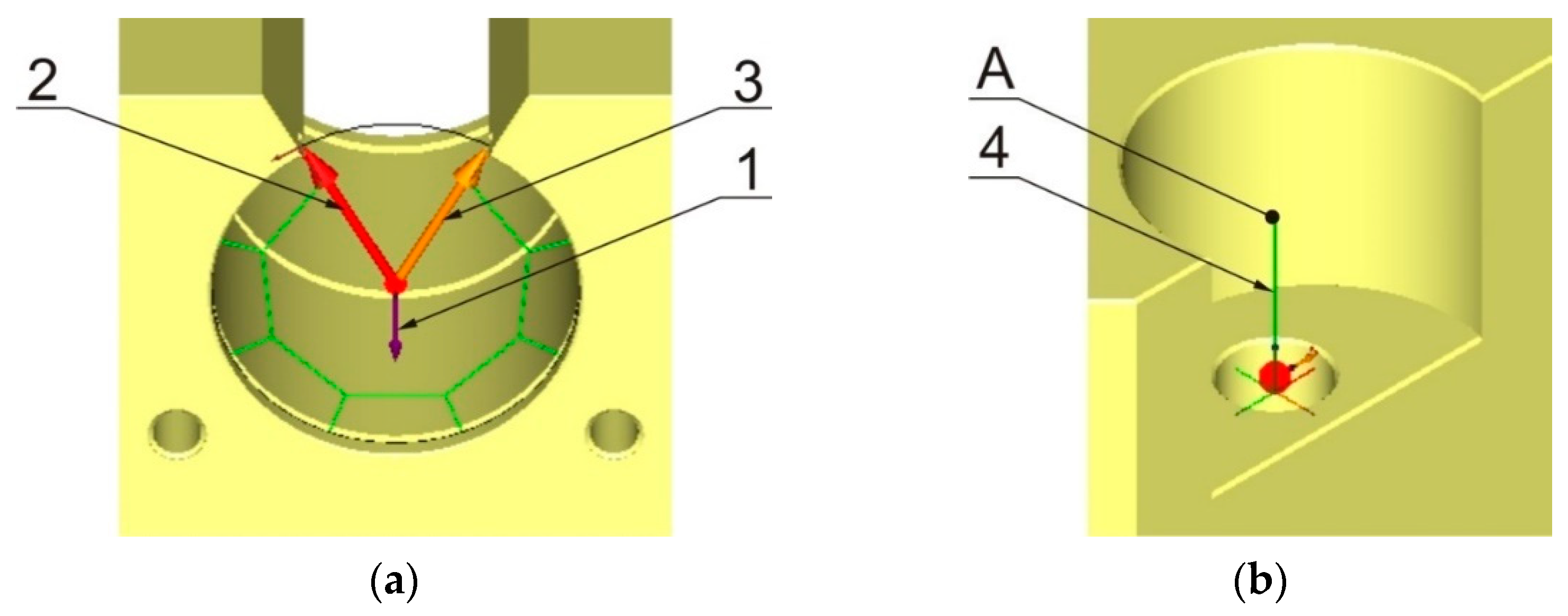
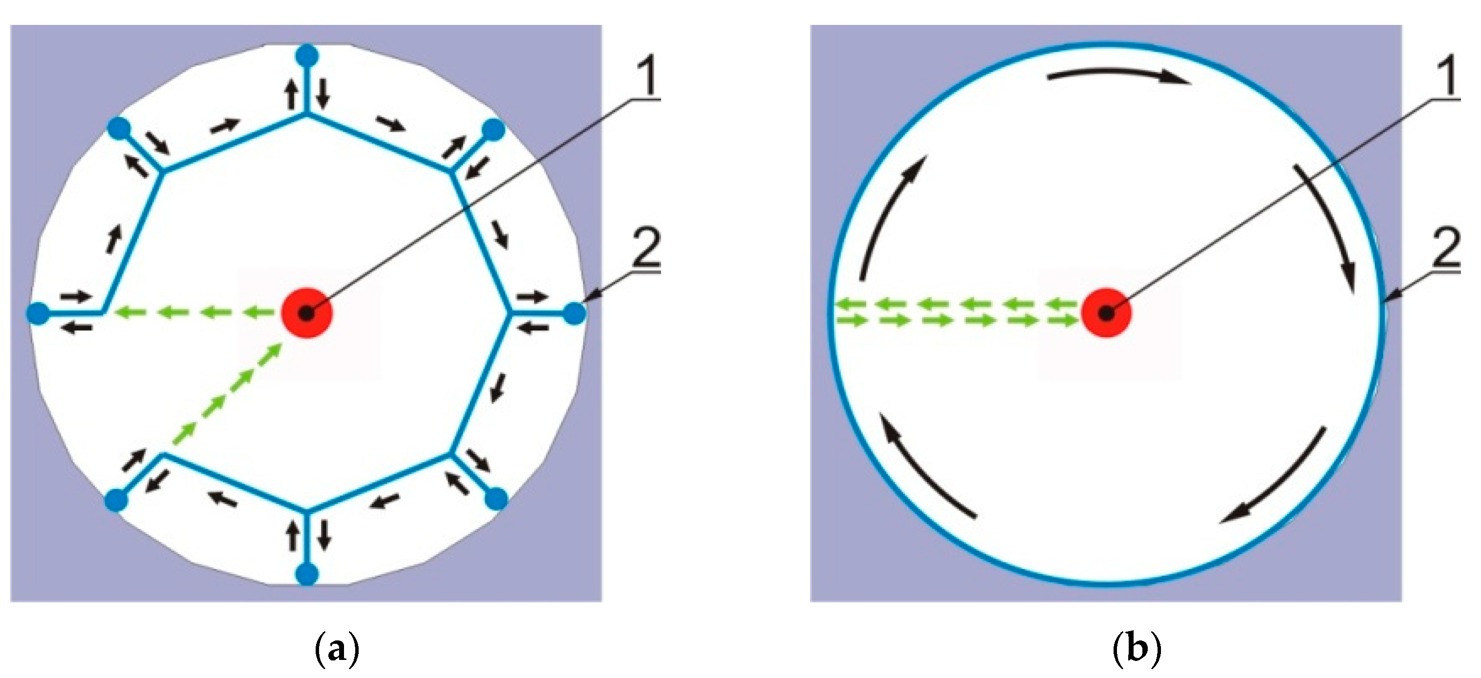
During the programming of the measuring task in the work environment PC-DMIS, for the part measured in the measuring position 1 and 2, the elements are defined by measuring and as automatic elements. For the automatic element of the circle, the parameters (
Figure 10a) are defined in the measuring program, such as centre, number of touches, angle of beginning and end of scanning (start and stop angle), direction of scanning (CW and CCW) and incursion (departure). Prior to scanning the circle, the scanning system will first move from any place to the point A and only then it will enter the opening on the designated trajectory with the goal to scan the given number of touches (
Figure 10b). This applies analogically also to the departure parameter.
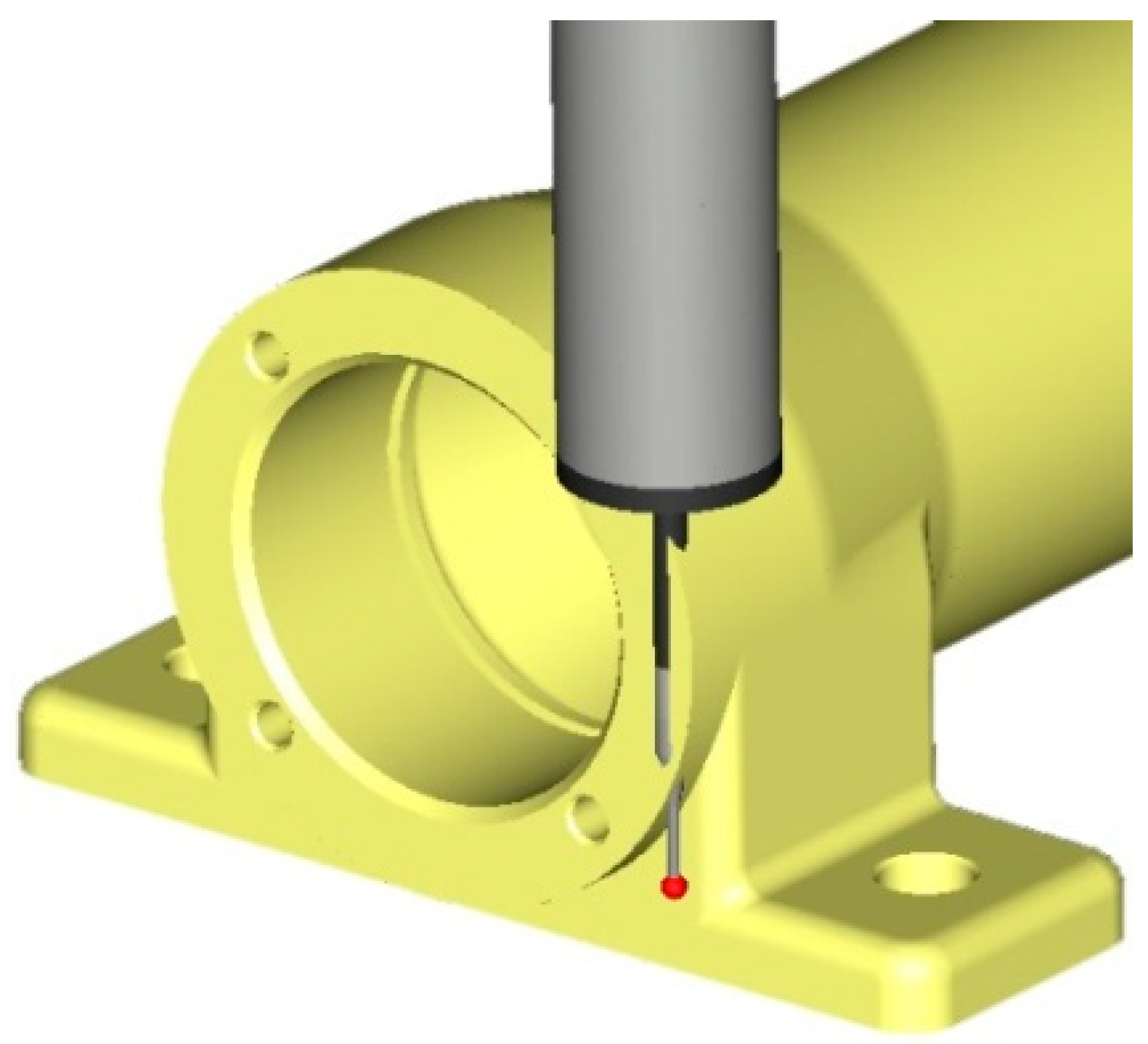
An automatic element of the vector point (
Figure 11) is used in the measuring program for the measuring positions 1 and 2. In the measuring programs for both measuring positions 1 and 2 all parameters (position in the coordinate system of the part and directional vector of the plane, which the point has been scanned from) of the surface point have been deducted from the imported parametric model of the measured part.
The geometric cylinder element designed by construction (in the measuring program CYL1) is necessary for defining the mutual position of the coordinate systems of the measured part and the coordinates measuring device. It is necessary to state that the direction of the directional vector of the cylinder is estimated by the order of selection of the elements CIR1 to CIR4 measured directly (
Figure 12).
4. Discussion
Before the direct running on the CMM, the measuring program has to be verified not only in terms of the kinematics of the movements during the measurement but also in terms of compliance with the correct technological procedure of the measurement.
Measuring and evaluating software PC-DMIS enables starting the prepared measuring program in the off-line simulation regime, during which collisions of the scanning system with the measured part, occasionally incorrectly placed contact places of the touch point with its surface, are identified. Simulation off-line in the work environment PC-DMIS was carried out for both prepared measuring programs (measuring program for measuring position 1, also for the measuring position MP2). During their simulation, a detection of collisions of the scanning system with the measured part was activated, which in the case of any collision will stop the operation of the measuring program and mark the point of its origin. Another function used not only during the off-line simulation but during the programming of the measuring task itself is a graphic display of the trajectory of the scanning system (
Figure 13).
Activation of this function has enabled to visually check the presence of excessive movements of the coordinate measuring machine based on the estimation, and the origin of possible collisions of the scanning system with the worktable of the device or with the measured part. Off-line simulation of the measuring program has pointed to the need to tune the prepared measuring program for the measuring position 1 as well as for the measuring position 2. On the basis of estimations, the coordinates of the position of several positioning points have been adjusted, and for the reason of removing excessive movements of the coordinate measuring device, the transfers of the coordinate system into the package plane have been removed in the cases where there was no threat of collision of the scanning system with the measured part. A debugged and collision-free measuring program for verification of observed geometric specifications of the device part in the measuring position 1 and 2 was verified on the coordinates measuring device DEA Global Performance 12.22.10. It was done at a considerably lower speed, as is the set measuring speed, and after confirmation of its faultlessness, a measuring in the measuring positions 1 and 2 was carried out on the stated coordinates measuring machine.
The principle of coordinate measuring is based on this assumption: “Each machine part consists of different geometric elements, such as e.g., plane, cone, cylinder, etc.” On coordinate measuring machines, points whose position is unambiguous in the defined coordinate system are sensed by contact of the touch tip of the sensing system with the surface of the measured part. The read coordinates of each scanned point are sent in real-time to the measuring and evaluation software. If the scanned points represent basic geometric elements, they are replaced by a corresponding substitute geometric element. To ensure the correctness of substitute geometric elements identification, it is necessary to observe the minimum number of scanned points for each of them (e.g., circle 3, line 2, etc.). As the number of scanned points increases, the substitute geometric element gets closer to reality, which increases the accuracy of the measurement. On the other hand, the measuring time increases, which causes an increase in the costs related to the measurement. At the end of the measurement, the dimensions, shape deviations and positions of the substitute geometric elements are compared with the nominal values of the dimensions, shape deviations and positions of the scanned elements of the verified machine part. Depending on the method of scanning of points on the surface of the verified machine part, a tactile measurement on coordinate measuring machines can be divided into:
Discontinuous tactile measurement (
Figure 14a)—scanning tactile system is moved away from the surface of the component after scanning each point, and when scanning the next point, it is moved to the surface again,
Continuous touch measurement—scanning (
Figure 14b)—we can speak about scanning in connection with the measurement, when we investigate deviations in the shape of a certain scanned surface and also in connection with reverse engineering, in which we determine the shape of the unknown scanned surface with the goal of creating its parametric model in reverse mode. In both cases, the touch tip of the scanning system is in continuous contact with the surface of the verified machine part during the point scanning.
In the presented paper, the verified machine part is the gearbox cover of the small tractor (
Figure 15), for which it is necessary to prepare a measuring program. The disadvantage is the lack of a parametric model, which does not allow the creation of a measuring program by off-line programming and debugging by simulation.
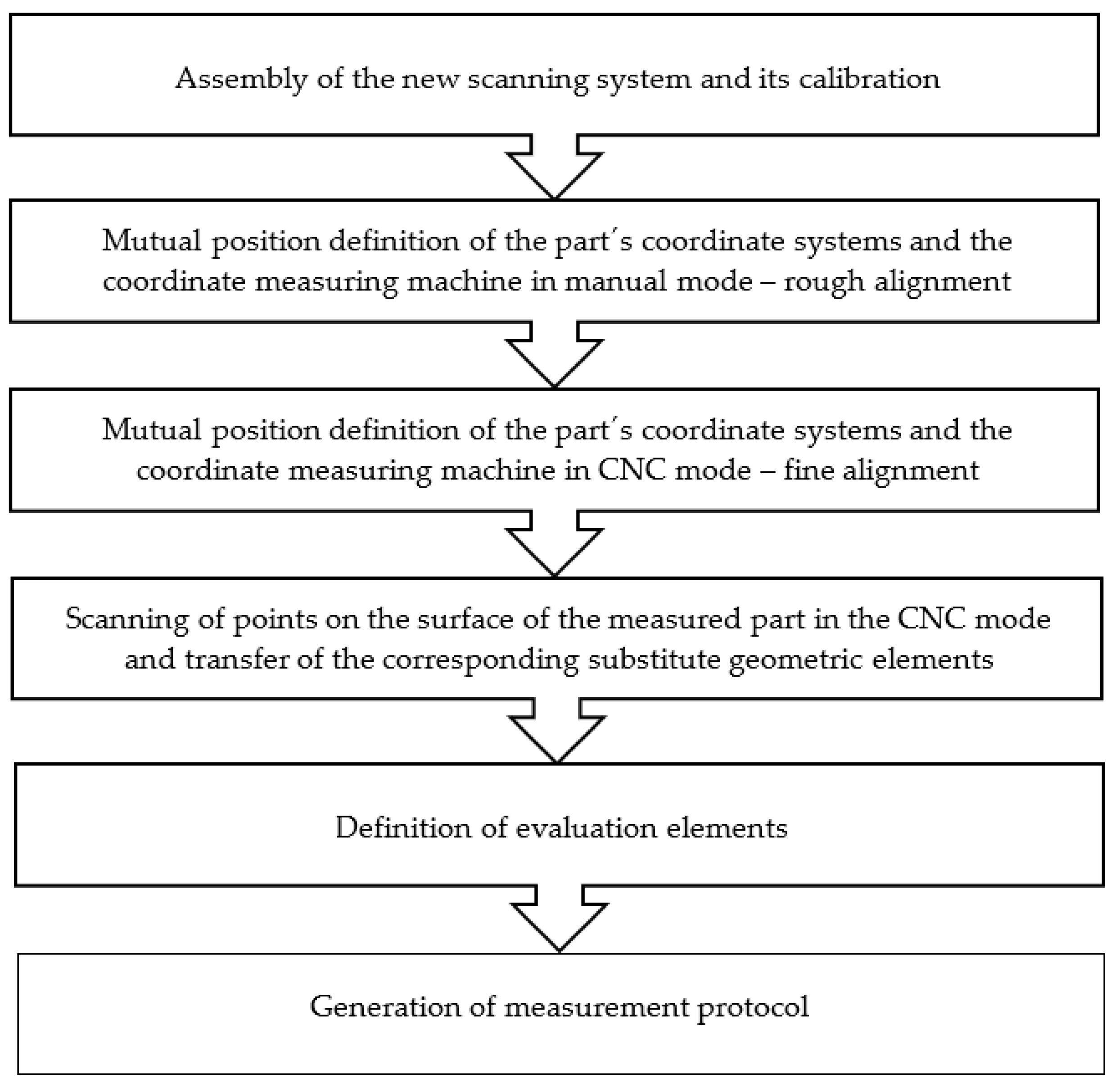
Since the number of elementary steps accompanies the creation of the repeatable and collision-free measuring program, it is appropriate to create a decomposition of the measuring task programming based on the analysis of the presented component (
Figure 16).
The scanning system, of which the contact length and the tip diameter allows to scan all necessary points for its verification on the surface of the part without collision, is constructed based on the shape of the verified machine part and its monitored geometric specifications. In order to achieve accurate measurement results, it is required to move the scanning system to the point of tip contact with the surface of the measured object along a path parallel to the normal of the surface on which the scanning points are located. In order to be able to verify all geometrical specifications prescribed by the drawing while complying with the requirement, a basic orientation of the scanning system is not sufficient. At the beginning of the new measurement, the position of the verified part in the working space of the coordinate measuring machine is not clearly defined. In order to create a repeatable and collision-free measuring program and to achieve reliable measurement results, it is necessary to define the mutual position of the coordinate systems of the part and the coordinate measuring machine. The definition of the mutual position of coordinate systems is called alignment.
“Alignment 3–2–1” can be included among the most basic and simplest ways of aligning the coordinate systems of a coordinate measuring machine and the measured part .
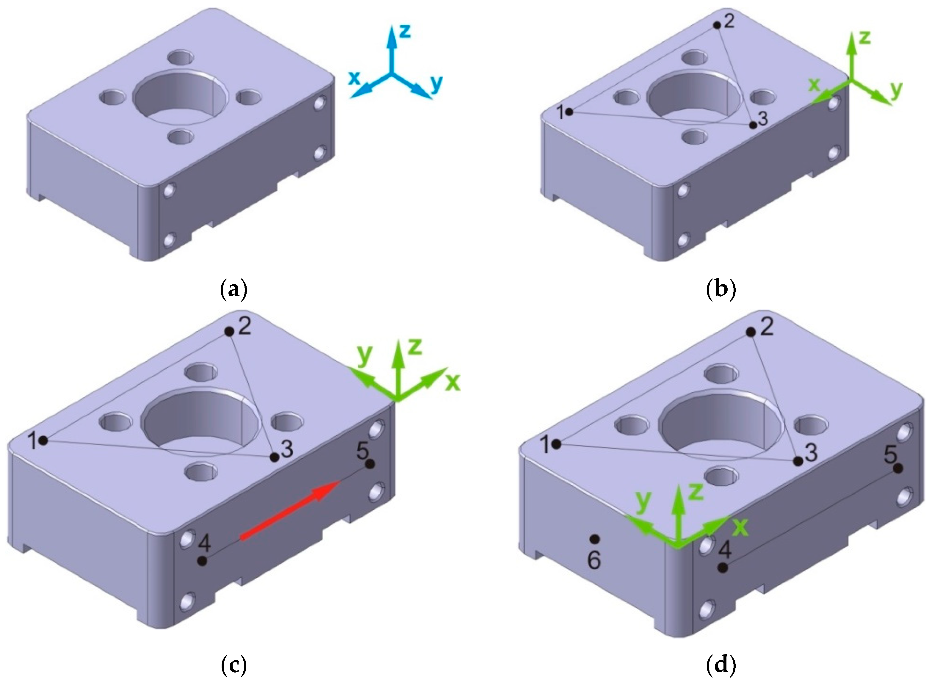
Our own alignment of the coordinate systems (
Figure 17) consists in the scanning of six points
,
i = 1, …, 6, which are on the surface of the measured part, while all points are scanned in the coordinate system of the coordinate measuring machine. The alignment points that form the coordinate system of the component have to be arranged on its surface so that they are on the most accurate, contiguous perpendicular surfaces.
The first three alignment points, , and , scanned on one surface of the measured part determine the plane translation, which is the coordinate plane xwyw of the part coordinate system. The next two points and are scanned on a surface perpendicular to the previous part surface. The plane passing through the points and is perpendicular to the previous plane and at the same time is the coordinate plane of the part coordinate system. The plane perpendicular to the previous planes passes through the last point scanned on the surface perpendicular to the previous two surfaces of the part, and this represents the plane of the coordinate system of the part.
The coordinate system of the component (
Ow,
xw,
yw,
zw) is now mathematically related to the coordinate system of the coordinate measuring machine (
Om,
xm,
ym,
zm). For the transformation matrix
T, which describes the translation and rotation between the given coordinate systems, the following applies (1):
The direction vectors
sxw,
syw,
szw of the individual coordinate axes
xw,
yw,
zw of the component coordinate system can be expressed as follows (2):
where
—relevant alignment points.
For directional cosines of the coordinate axes
xw,
yw,
zw of the coordinate system of the component with respect to the coordinate system of the coordinate measuring machine (3):
Until the mutual position of the coordinate systems is defined, the coordinates of all scanned points are expressed in the machine coordinate system, and only then are all scanned points expressed in the current coordinate system of the part.
- b.
Rough alignment.
During the rough alignment, the individual points are scanned in manual mode, which means that the touch tip of the scanning system does not touch the surface of the measured part with a constant force at all scanned points, and therefore, it is not possible to speak about a sufficiently precise definition of the mutual position of coordinate systems. The alignment ensures only the initial position determination of the verified machine part in the working space of the coordinate measuring machine, which in the next steps allows performing all working movements with the control unit in the CNC mode. For rough alignment of coordinate systems, it is necessary to scan on the surface of the measured part (
Figure 18):
Three points PNT1, PNT2, PNT3 to define the plane; subsequently, the z axis direction from the coordinate system of the part is identified with the direction of the direction vector by three points of the defined plane,
The circles CIR1 and CIR2, where the order of their selection determines the direction vector v; the coordinate system of the part is then rotated about the z-axis so that the direction of the x-axis is identical with the direction of the direction vector v,
The circle CIR3 as the available drawing documentation determines the position of the origin of the part coordinate system at its prescribed zero point (
Figure 18). This requirement is met when the origin of the
x-axis and also the origin of the
y-axis are shifted into the scanned circle CIR3. The last step is the movement of the origin of the
z axis to the plane scanned using points PNT1, PNT2 and PNT3.
- c.
Fine alignment.
Compared to rough alignment, the basic difference between is the controlled movements managed by the control unit of the coordinate measuring machine, which ensures that all points required for alignment of the scanning system to the point of contact of the contact tip with the surface of the part are scanned with constant force and constant approach speed. With the mentioned constant parameters, in addition to the points required for fine alignment, all required elements of the verified machine part are scanned, which is a basic prerequisite for achieving correct measurement results of precise machine parts. For fine alignment of coordinate systems, the same elements are scanned on the surface of the verified machine part as by rough alignment, while their replacement geometric elements are determined from several scanned points.
- d.
Scanning of elements necessary for evaluation of verified geometric specifications.
The technical documentation of the machine part clearly specifies which geometrical specifications are necessary to be verified. Therefore, all necessary points are scanned on their surface. Based on computational algorithms, they are translated with substitute geometric elements representing the real elements on the part. As the scanning system moves during scanning, it is necessary to avoid its collision with the measured part. In this case, the usage of the so-called envelope plane is the most suitable way for elimination of possible collisions (
Figure 19).
- e.
Definition of evaluation elements and generation of measurement protocol.
In the last phase of the measuring program preparation, an evaluation element is assigned to each replacement geometric element, which relates to the nominal value read from the technical documentation and the associated tolerance. Deviations in the size, position and shape of the substitute geometric elements then represent deviations from the nominal value of the dimension, position and shape of the actual element on the part. The output phase of the measuring process becomes a measuring protocol, which gives clear information on whether the verified machine part meets the given requirements or becomes repairable or a not-reparable failure. In addition to the nominal value and the associated tolerance, the measurement protocol also shows the measured value, its deviation from the nominal value and from the tolerance band, which is expressed both numerically and graphically.
4.1. Plan and Implementation of the Experiment
The design of the experiment is based on the approach of measuring a calibrated work piece with the same sequence of measurements, in the same way, with the same measuring device and under the same conditions as in real measurements in the production plant. Based on the work piece measurement on a laboratory coordinate measuring machine, a value estimate of the deviation of the surface parallelism and the associated measurement uncertainty, which is the total standard uncertainty of the calibrated work piece measurement, is obtained. Subsequently, the parallelism deviation of the surface of the calibrated work piece is measured with the usage of the coordinate measuring machine representing the measuring instrument. This simulates the measurement in the production plant. For each measurement, a new coordinate system of the component is created, in which the deviation of the surface parallelism is evaluated 30 times. The component coordinate systems used in the individual measurements are formed with a mutually different distribution of the same number of points scanned on the same surfaces of the calibrated work piece. The estimate of the extended measurement uncertainty of the surface parallelism deviation is expressed for the coordinate measuring machine representing the measuring instrument according to STN EN ISO 15530-3 as follows:
where
ucal—standard measurement uncertainty of a calibrated work piece determined by a laboratory coordinate measuring machine,
up—standard measurement uncertainty caused by the measuring process,
uw—standard uncertainty of the production process, |
b|—systematic error,
k—expansion coefficient.
The achieved measurement results of a calibrated work piece on a coordinate measuring machine that represents the measuring instrument are in
Figure 20. The graphical representation shows the dependence of the estimated value of surface parallelism deviation with expanded measurement uncertainty expressed for expansion coefficient
k = 2 and the distribution of the alignment points of the coordinate systems used in the individual measurements.
4.2. Conformity Assessment of the Produced Component with the Technical Documentation
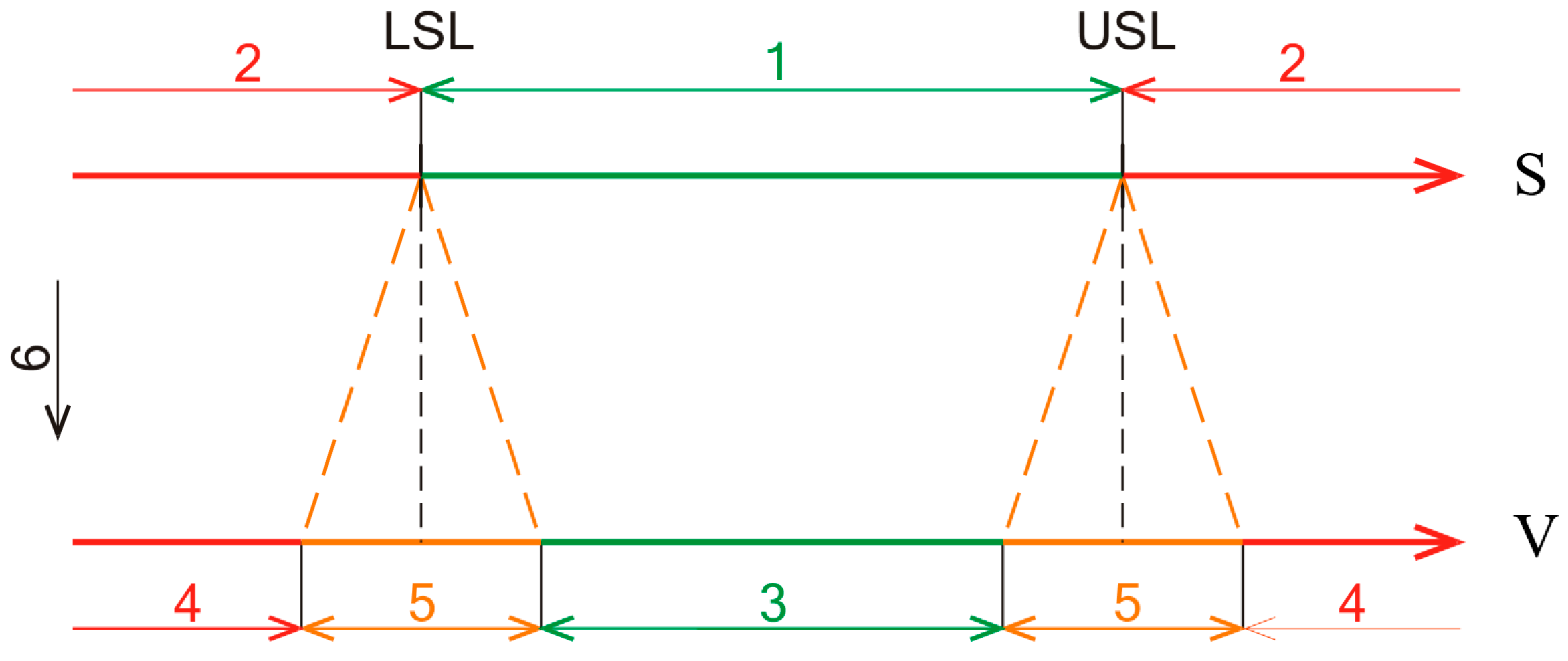
In connection with the conformity assessment of geometric parameters of products with the technical documentation, the meaning of the terms geometric parameter compliant or non-compliant with the relevant technical documentation is complicated by the uncertainty of measuring the assessed parameter, which plays an important role in determining conformity. At present, the conformity assessment of the produced part with the technical documentation is performed in accordance with the international standard STN EN ISO 14253-1, which changes the uniform demarcation of the lower and upper specification limits to uncertainty intervals (
Figure 21). It is clear that the range of values for which it is possible to decide about the conformity of the produced component with the technical documentation narrows with increasing measurement uncertainty, and thus, the number of components whose conformity with the technical documentation is not uniform increases. On the other side, the number of components that can be classified as compliant with the technical documentation will decrease at the same production costs. The problem of uniform determination of the conformity of the measured geometric parameter with the technical specification occurs when the measurement result is within the range of uncertainty, when the conformity cannot be declared.
In the case of evaluating the deviation of the surface parallelism relative to the base, in which the coordinate plane of the part coordinate system is assigned as an integral element, the uncertainty of this deviation is influenced by how the position of the coordinate systems is defined, which ultimately affects the distribution of points scanned during alignment. If the production process under the same conditions has to be the process without failures or components whose conformity with the technical specification is not clear, the conformity assessment process has to be taken into account at the design and development stage of the product. At this stage, new specification limits are determined to take into account not only the functionality of the produced component but also the expected measurement uncertainties, the size of which is also affected by the definition of the relative position of the coordinate systems.
At the workplace of one of the authors, similar control measurements of components were performed, which were used for verification of the technological procedures of components production, or correction of tools for machining on CNC machines. At the same time, CMM serves as a part of the learning process in professional subjects at the faculty.


 —directional vector of the plane,
  —direction of scanning.

 directional vector of the plane,
  direction of scanning.