Article

A Few MeV Laser-Plasma Accelerated Proton Beam in Air Collimated Using Compact Permanent Quadrupole Magnets

1
Consiglio Nazionale delle Ricerche, Istituto Nazionale di Ottica, 56124 Pisa, Italy
2
Istituto Nazionale di Fisica Nucleare (INFN), Sezione di Pisa, 56127 Pisa, Italy
3
Istituto Nazionale di Fisica Nucleare (INFN), Sezione di Firenze, 50019 Sesto Fiorentino, Italy
4
Consiglio Nazionale delle Ricerche, Istituto di Fisiologia Clinica, 56124 Pisa, Italy
*
Authors to whom correspondence should be addressed.
These authors contributed equally to this work.
Current address: Accelerator Physics Group, Cockcroft Institute, Department of Physics and Astronomy, The University of Manchester, Manchester M13 9PL, UK.
Appl. Sci. 2021, 11(14), 6358; https://doi.org/10.3390/app11146358
Submission received: 12 May 2021 / Revised: 3 July 2021 / Accepted: 6 July 2021 / Published: 9 July 2021
(This article belongs to the Special Issue Laser-Driven Accelerators, Radiations, and Their Applications)

Abstract

:
Proton laser-plasma-based acceleration has nowadays achieved a substantial maturity allowing to seek for possible practical applications, as for example Particle Induced X-ray Emission with few MeV protons. Here we report about the design, implementation, and characterization of a few MeV laser-plasma-accelerated proton beamline in air using a compact and cost-effective beam transport line based on permanent quadrupole magnets. The magnetic beamline coupled with a laser-plasma source based on a 14-TW laser results in a well-collimated proton beam of about 10 mm in diameter propagating in air over a few cm distance.

1. Introduction

After decades of fundamental research in laser-plasma particle acceleration, nowadays this novel acceleration technique is experiencing a great impulse towards implementation for practical applications. The possibility to achieve laser-based particle acceleration with a compact setup is a very appealing factor for the development of high-quality electron [1] and proton/ion [2] accelerators. Specifically concerning protons, a few to hundreds of MeV particle energy can be achieved via laser-based acceleration [3,4]. Some examples of envisaged or already implemented practical applications of laser-accelerated protons are radiotherapy with tens to hundreds of MeV protons [4,5], as well as the radiography of laser directly-driven implosions [6] and imaging of fast laser-generated magnetic fields [7,8,9] with tens of MeV protons. Concerning lower energy beams, a few MeV protons can be used for material characterization and surface/superficial processes [10], like Particle-Induced X-ray Emission (PIXE). PIXE is a high-sensitivity non-destructive analysis technique that enables to perform quantitative characterization of the surface elemental composition of materials by measuring the characteristic X-ray emission induced by proton irradiation [11]. PIXE is typically implemented using 2 to 3 MeV proton beams from classical electrostatic accelerators.
Pulsed proton beams with a few MeV particle energy can indeed be efficiently generated with laser intensities of about 10 19 W/cm 2 via the so-called Target Normal Sheath Acceleration (TNSA) process [3,4,12,13,14,15]. Briefly, in the TNSA process, an ultraintense laser beam is focused on a thin solid target creating a hot plasma; the fast electrons thereby generated are ejected, inducing a strong electric field normal to the rear surface of the TNSA target; protons and ions are then accelerated by such a high field. Intensities needed to trigger the TNSA process are routinely achieved using laser systems with a peak power of tens of TW which can run at a repetition rate up to 10 Hz, and are nowadays available in many research laboratories worldwide as well as commercially available as standard products [16,17].
The implementation of laser-plasma accelerated proton beams for PIXE application have been recently investigated [18,19,20,21,22,23], mainly with modeling and simulations. In [18], a detailed analysis is performed by a Monte Carlo simulation of PIXE measurements using a realistic laser-driven few MeV proton source with broad band energy spectrum and a single photon counting CCD camera for spectral analysis of the X-ray emission from the irradiated sample. Interestingly, it was shown that implementing measurements with different energy distributions, i.e., cut-off energy, can allow to extract quantitative information of inhomogeneous samples, i.e., with a depth-dependent elemental composition, performing the so-called “Differential PIXE” measurements [24]. Indeed, the cut-off energy of laser-accelerated protons can be tuned by adjusting the laser-plasma interaction conditions, as for example the position of the TNSA target with respect to the laser focus. In [19], a Monte Carlo simulation of laser-driven PIXE experiments using few MeV laser-accelerated protons is presented, showing the feasibility of measurements on materials of importance for the cultural heritage context. Of particular importance, in [20], the effect of the TNSA fast electrons on the PIXE signal have been analyzed and quantified. Simulations showed that the contribution of such fast electrons is not negligible, and therefore their removal from the beam path is mandatory. In [21], measurements are reported of the characteristics X-ray emission from samples in vacuum after single pulse irradiation with laser-accelerated particles generated using the very powerful TITAN laser of the Jupiter Laser facility at Lawrence Livermore National Laboratory. In [22], a detailed study is reported on the design of a magnetic beamline for laser-accelerated proton energy up to 20 MeV and the final spot of about 10 mm 2 , comprised of focusing with magnetic quadrupoles and energy selection with a magnetic chicane. In [23], a detailed experimental investigation on the use of a laser-driven particle source for quantitative PIXE analysis and EDX spectroscopy in vacuum is reported.
In general, a key and very appealing characteristic when using few MeV protons for practical applications is the possibility of having access to the particle beam in ambient atmosphere, i.e., with external beam [25]. This allows one to easily irradiate a sample in atmospheric conditions, which is necessary when the sample cannot be placed in vacuum (e.g., biological specimen and samples containing volatile components [26,27,28]), or when many samples have to be analyzed in a limited period of time avoiding sample exchange in vacuum (e.g., aerosol samples [29,30]). Although the proton beam accelerated via TNSA propagates mainly towards the direction normal to the rear side of the laser-plasma target, it has a divergence of typically 10 to 15 half-angle [31,32,33,34]. Therefore, for practical use of the laser-accelerated protons, a magnetic transport beamline has to be implemented in order to transfer the protons from the TNSA source to the application site [22,31,35,36]. Moreover, the magnetic beamline (MBL) can remove the unwanted fast electrons created during TNSA.
Here we report about the design, implementation, and characterization of a few MeV laser-plasma-accelerated proton beamline in air using a compact and cost-effective proton transport based on permanent quadrupole magnets. The MBL is coupled with a TNSA laser-plasma proton source based on a 14-TW laser, resulting in a collimated few MeV proton beam of about 10 mm in diameter propagating in air over a few cm distance.

2. Results and Discussion

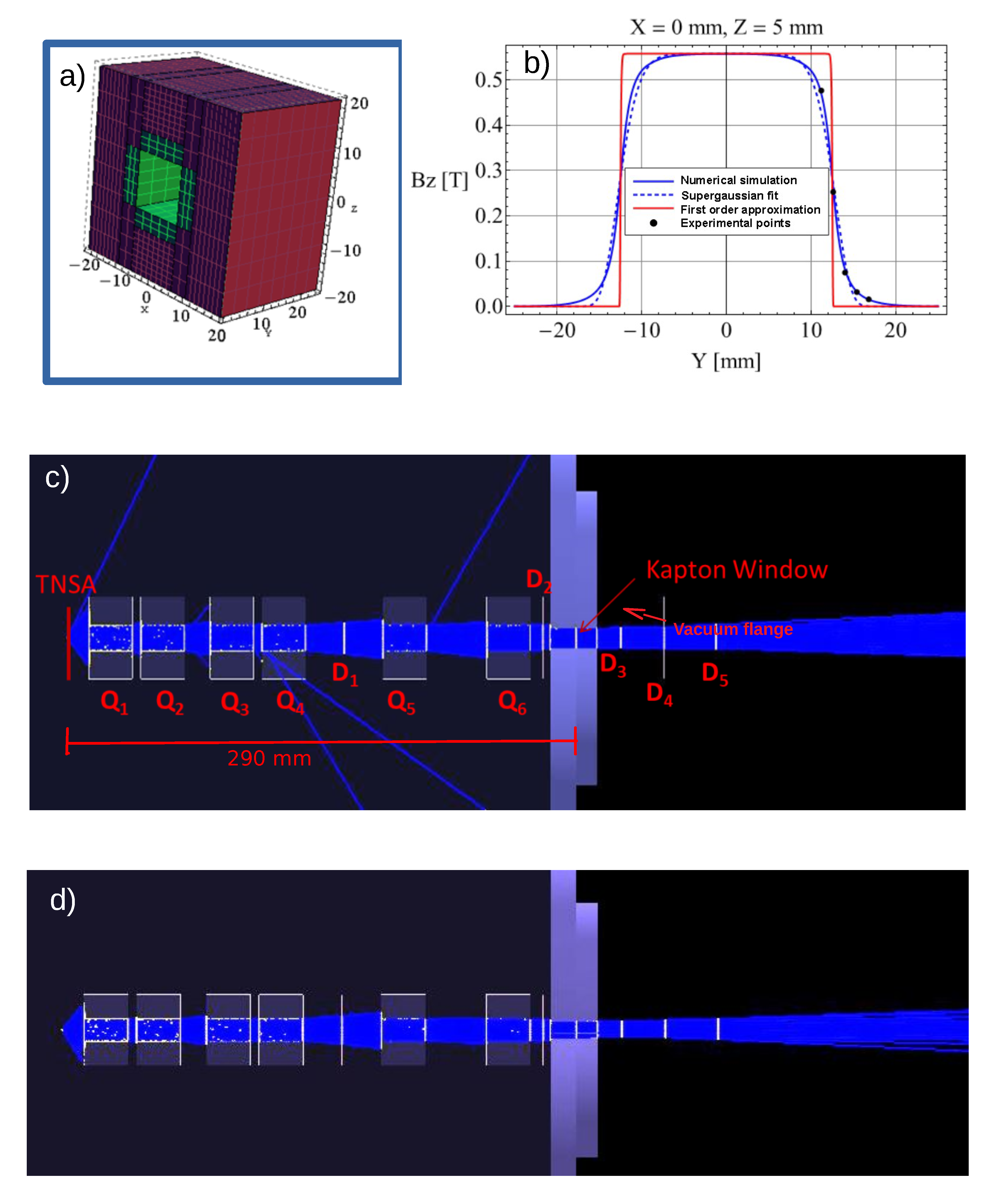
2.1. Magnetic Beamline Design
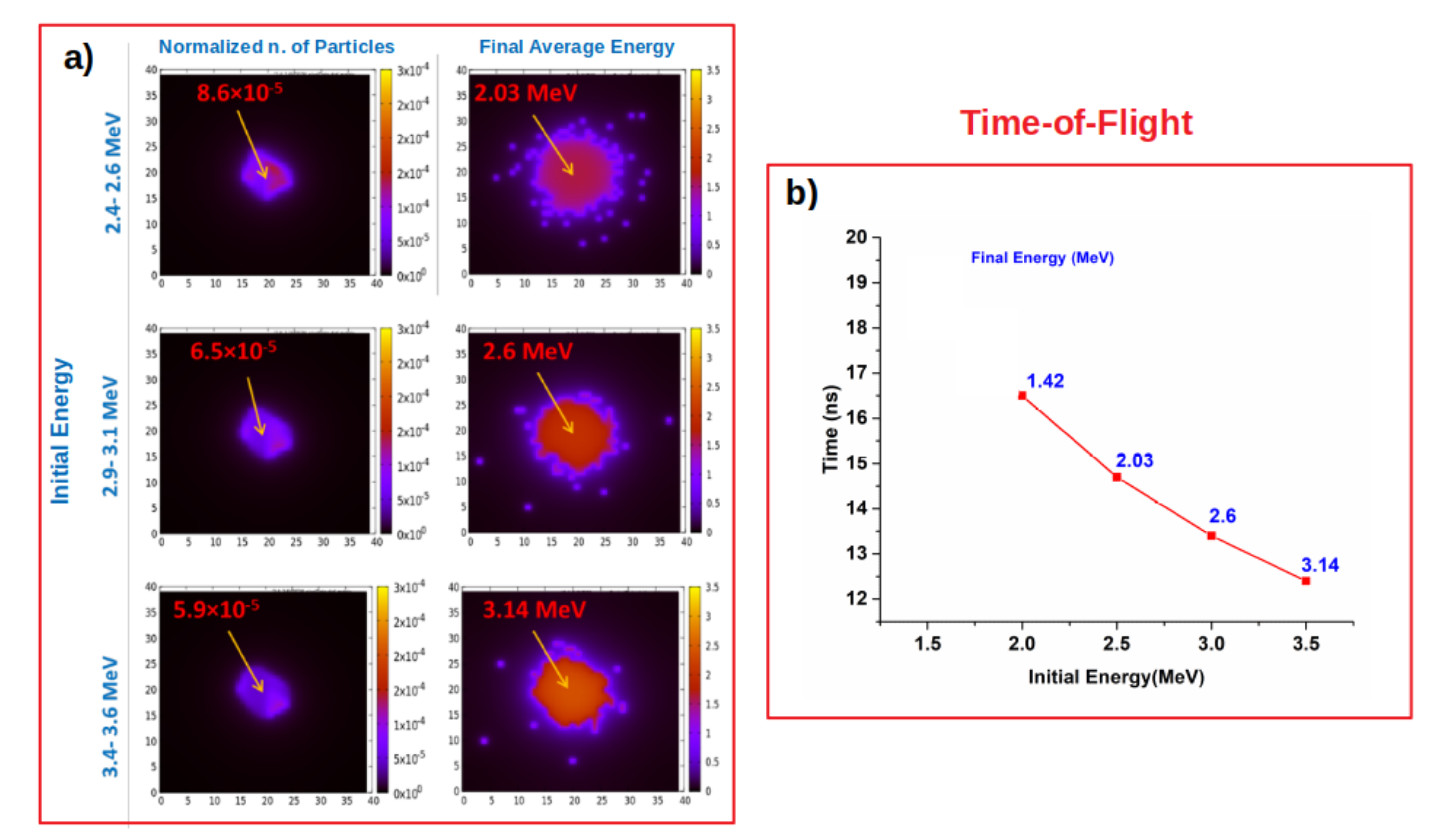
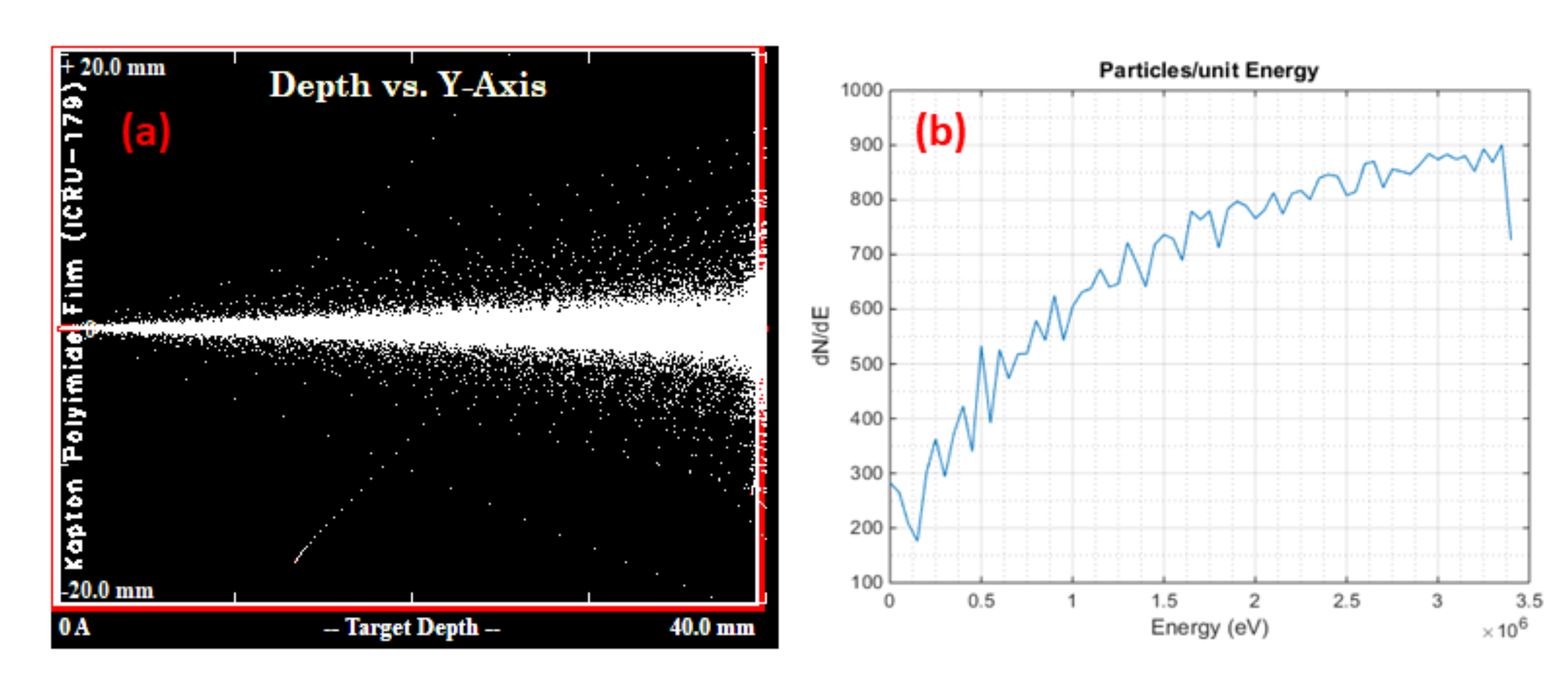
The MBL is specifically designed to achieve a few MeV proton beam of about a 10-mm diameter collimated over a few centimeters in length when propagating in air.
The MBL consists of magnetic quadrupoles comprising standard neodymium-based commercial permanent magnets of 25 × 12 × 4 mm 3 dimensions that are embedded in a soft iron supporting cage, as shown schematically in Figure 1a. The simple design and components of the developed permanent quadrupoles results in a compact and cost-effective beamline.
The transport of the laser-accelerated protons through the MBL is studied using the Monte Carlo GEANT4 toolkit [37] (see Methods for details). An analytical function for the magnetic field of the quadrupoles is used in the GEANT4 simulations. Such a function is obtained by fitting the magnetic field numerically, reconstructed from actual measurements, of which an example is reported in Figure 1b (see Materials and Methods for details). In Figure 1b, the truncated ideal quadrupole magnetic field is also reported as a reference for comparison. The aim of the simulation is to find a configuration of the MBL that efficiently transfers the few MeV divergent proton beam from the TNSA source to a collimated beam in air. The proton beam exits the vacuum chamber through a Kapton window of a 10-mm diameter and 13- μ m thickness, which sustains a vacuum to the 10 4 mbar level. The compact MBL set-up comprises six quadrupole magnets placed with alternating field orientation and gaps of 5 mm, 15 mm, 5 mm, 45 mm, and 35 mm between each other starting from the TNSA source side. The total length of the MBL is 255 mm. The first quadrupole is placed at 12.5 mm from the TNSA source and the overall distance between the Kapton window and the TNSA source is measured to be 290 ( 5 ) mm. In Figure 1c,d the schematics of the two orthogonal transverse cross sections of the MBL are shown along with the simulated proton beam trajectories (see Materials and Methods).
The characteristics of the proton beam transported in air is evaluated in details by performing simulations at an initial proton energy in narrow ranges. In Figure 2a, the particle distribution and the final energy obtained in air at 1 cm after the Kapton window are reported for initial energy in the ranges 2.4 to 2.6 MeV, 2.9 to 3.1 MeV, and 3.4 to 3.6 MeV. To compare with the experimental measurements, the time-of-flight (ToF) of the protons as a function of the initial energy is also evaluated. The graph reported in Figure 2b shows the ToF as well as the final energy considering the transport through the MBL, the Kapton window, and 1 cm of air at ambient conditions.
The properties of the proton beam when propagating in air are analyzed using the software SRIM [38]. Figure 3a reports the proton trajectory for an initial point-like beam with a flat energy spectrum, from 4.0 to 1.7 MeV, impinging normally to the 13- μ Kapton window and propagating through 4 cm of air. The resulting final spread of the beam in the transverse direction is in the order of a few mm. The graph in Figure 3b shows the final energy distribution after propagation through the Kapton window and the 4 cm path in air, with a sloping down trailing energy tail to zero energy, due to convolution with energy straggling effects and partial stopping of the lower energy protons (the range of 1.7 MeV protons in air, after losing energy in passing through the Kapton window, is 3.9 cm).
In order to evaluate the effect of the MBL on the fast electrons produced during the TNSA process, a GEANT4 simulation assuming a flat energy distribution between 0.1 and 1 MeV is performed. The result of such a simulation experiment is reported in Figure 4 and clearly shows that the fast electrons are very efficiently filtered out by the MBL.

2.2. Experiments

A schematic representation of the compact laser-based accelerator realized and tested is reported in Figure 5. The laser system used is the TW laser beamline at the Intense Laser Irradiation Laboratory of the CNR-INO in Pisa [39]. The laser beam is guided by multiple steering mirrors to an off-axis parabolic (AOP) mirror. The intensity in the focus is estimated to be several times 10 19 W/cm 2 (see Materials and Methods). The TNSA laser target used is a 5-micrometer thick titanium foil, whose position is controlled by a three-axis motorized stage with micrometer resolution. An optical camera is used to image the laser target in order to control the position of the laser focus on the titanium foil.
In Figure 6, the picture of the actual compact laser accelerator is reported, showing the laser beam transport line, the OAP mirror, the TNSA laser target, the MBL, and the Kapton window. The MBL is supported by a motorized linear stage that can be remotely controlled to insert and remove the MBL from the proton beam path.
The energy of the laser-generated proton beam is characterized with ToF measurements with the particle detector placed in air at 1 cm after the Kapton window. In Figure 7, the typical ToF traces measured with and without the MBL are shown. These data represent the maximum cut-off energy which is achieved when optimizing the TNSA process. When the TNSA target is moved out from the optimal position, proton beams with lower cut-off energy are obtained.
The actual cut-off energy value is inferred from the ToF data by the onset of the steep rising edge of the proton signal relative to the reference time corresponding to the laser-plasma interaction on the titanium foil target (t = 0). Such a reference time is set at 1.0 ns before the onset of the first ToF peak which is due mainly to the fast electrons with a contribution from X-rays from the laser-plasma (see Material and Methods Experiments section for details). The maximum cut-off proton energy achieved is ≈3 MeV in agreement with reported scaling law for the TNSA process [34,40]. The uncertainty on the cut-off proton energy determined by ToF measurements is estimated to be 0.2 MeV (see the Material and Methods Experiments section for details). Importantly, the first peak in the ToF traces is suppressed when using the MBL, confirming that fast electrons are removed from the proton beam path.
Radiochromic EBT3 films [41] are used to characterize the spatial distribution of the proton beam in air and to perform dosimetry. The results from EBT3 film irradiation experiments are reported in Figure 8. For direct and easier comparison between simulations and experiments, Figure 8a shows the particle distribution from GEANT4 simulation at 1 cm after the Kapton window considering a beam with a flat initial energy distribution from 1.7 MeV to 3.5 MeV. In Figure 8b, the image of the EBT3 film at 1 cm after the Kapton window irradiated by 8 shots is reported. In Figure 8c, the image of the EBT3 film at 4 cm after the Kapton window irradiated by 15 shots is reported showing slight ellipticity of the proton beam due to the MBL. The experimental measurements show a good agreement with the simulated beam reported in Figure 8a. The proton beam after 4-cm propagation in air shows a smoother profile with a few mm gradient region at the edge of the beam in agreement with the SRIM calculations. These results confirm that the MBL is producing a well-collimated proton beam for several centimeters in the air.
The delivered dose is evaluated from the optical density of the scanned EBT3 radiochromic film and the calibrations reported for mono-energetic protons [42,43]. Thus the calculated average dose is 1 Gy/shot and 0.4 Gy/shot after propagating in air for 1 cm and 4 cm respectively with an uncertainty estimated to be in the order of 20% (see the Material and Methods Experiments section). The reduced dose measured further away from the Kapton window reflects the loss of lower energy protons in air, as from the calculations reported in Figure 3b. The proton particle fluence per shot after propagating 4 cm in the air is estimated to be 3 × 10 7 cm 2 .

3. Conclusions

A laser-accelerated proton beamline delivering 3-MeV particle energy has been conceived, designed, realized, and tested, aimed at practical applications, like PIXE measurements. The proton source used is based on the TNSA process and implemented using a 14 TW laser system. Quadrupole permanent magnets are used to transport the protons from the TNSA source to the sample site in air through a thin Kapton window. The magnetic beamline design is compact and cost-effective and has been defined using Monte Carlo simulations in order to achieve a collimated proton beam over several cm in length, as well as to remove unwanted fast electrons from the beam path.
From dosimetry measurements, the number of few MeV protons after propagating 4 cm in air is estimated to be 2 × 10 9 in 100 shots, which is on the same order as the number of protons impinging on the PIXE sample used in the simulation experiments reported in [18,19]. This finding indicates that PIXE measurements are feasible with the presented laser-plasma accelerated proton beamline within tens of seconds assuming a 10-Hz repetition rate operation. Finally, it is noted that the energy spectrum of the laser-accelerated proton beam can be easily tuned (by moving the TNSA target with respect to the laser focus) in order to have different cut-off energies, therefore allowing to implement differential PIXE measurements of in-homogeneous samples in depth [18].

4. Materials and Methods

4.1. Quadrupole Magnets

Each magnetic quadrupole comprises 4 permanent neodymium-based magnets of a 25 × 12 × 4 mm 3 dimension with a nominal surface field of 1.2 T. The magnets are arranged with the field alternatively oriented in a soft iron frame of a 40 × 40 × 25 mm 3 dimension to gives a quadrupole field at the first order. This represents the simplest quadrupole design allowing, at the same time, for the largest effective free aperture. However, in the case of a square aperture bounded of permanent magnets, the quadrupole field cannot be approximated as an ideal field as the equipotential surfaces are not hyperbolic. For this reason, the actual field has been carefully measured and then simulated to obtain a proper approximation of the relative multipole field expansion.
The orthogonal component of the magnetic field has been measured using a Hall probe along parallel paths taken at different distances from the entrance. Using these results as matching points, the complete 3D field has been simulated using Radia [44,45], a software package build in C++ and interfaced with Mathematica (Wolfram Research). The focusing/defocusing properties of each device has been preliminary calculated using [46]:
f c = 1 / k sin ( k L ) 8.4 cm , f d = 1 / k sinh ( k L ) 7.4 cm
for focusing and defocusing length respectively, where k = ( q x B x / p ) 1 / 2 was calculated for 3-MeV protons with q and p the proton charge and momentum, respectively. The considered transverse gradient was x B x = 110 T/m while L = 25 mm is the longitudinal quadrupole length. In terms of these parameters, the whole design of the magnetic line, which is made of six elements, has been roughly defined according to the classical thick lens equation. The preliminary design takes into account that it is possible (in ideal conditions) to focalize a monoenergetic bunch in the same point in both orthogonal planes using a combination of identical devices. This properties follows from ( k L ) 2 0.35   / 1 , which implies remarkably different focal lengths f c f d (see Equation (1)). Clearly, the whole guiding system remains intrinsically astigmatic as the case of the thin lens approximation. Finally, the fine optimization has been obtained through several tests performed with GEANT4, in which an analytical model for the 3D magnetic field has been implemented to take into account the fringe field. An analytical approximation has been chosen instead of the complete Radia fields in order to drastically speed up the simulation process. No relevant differences has been observed in the final results considering a realistic protons bunch. In more detail, the transverse component of the field was used B = A ( B x , 0 , B z ) , where A is a supergaussian amplitude, while the B x , z components are given by:
B x = K 0 K 1 2 z 4 x + K 1 z 2 K 1 10 x 2 x 3 , B z = K 0 K 1 2 x 4 z K 1 x 2 K 1 10 z 2 z 3 ,
where k 0 and k 1 are free fit parameters. Expressions (2) can be directly obtained trough a Taylor’s expansions considering a square symmetry and the divergenceless and irrotational conditions on the fields.

4.2. Monte Carlo Simulations of the Quadrupole Beamline

The entire quadrupole beamline was designed and simulated using a code developed on purpose using the GEANT4 library toolkit [47,48]. In particular, all the volumes/materials making up the quadrupole structure were taken into account (as it can be realized looking at Figure 1 and Figure 4), as well as the detailed vacuum flange and Kapton window structures. The expressions given in Equation (2) were used for the magnetic fields. The G4EmPenelopePhysics physics list was used. For each run, a total number of 2.5 × 10 7 primary protons (or electrons, in the case shown in Figure 4) was used. The angle ϑ between the original direction of each primary particle and the symmetry axis of the system is distributed according to a gaussian function, i.e., P ( ϑ ) e x p ( ϑ 2 / σ ϑ 2 ) , with σ ϑ 13 . According to the existing literature, this is a typical value for few MeV TNSA protons [31,32,33,34]. For each run, the total number, mean energy, r.m.s. energy, and average arrival times of the particles of interest (protons or electrons) were sampled on one (or more) virtual plane (“detectors”) perpendicular to the main symmetry axis; this plane was sampled using “virtual pixels” with a typical size of 0.5–1 mm .

4.3. Experiments

For the experiment reported here, the 800-nm Ti:Sapphire “TW” laser beamline at the Intense Laser Irradiation Laboratory of the CNR-INO in Pisa was employed. This laser beamline provides a 30 fs duration, 450 mJ energy pulses, with an M 2 factor close to 1.5. The laser beam was focused on the TNSA target foil with a 15 angle of incidence using an f / 1.5 Off-Axis Parabola (Thorlabs Model MPD229-M03: Gold coating—focal length 50.8 mm—90 off-axis angle, reflected wavefront error < λ /2 at 633 nm). The final intensity on the target is estimated to be about 7–8 × 10 19 based on the optical quality of the low-cost OAP.
The ToF measurements were performed in air using a Si PIN diode biased with a voltage of about 80 Volt as the particle detector. An oscilloscope (Lecroy-Waverunner 64Xi, 600-MHz bandwidth, and 5-GS/s sampling rate) is used to acquire the ToF detector signal. The time “zero” on the ToF traces is set relative to the X-ray/fast electrons peak that is 1.00(2) ns (given a target to Si PIN detector distance of 300(5) mm) after the proton starting time which coincides on a picosecond time-scale with the laser pulse arrival time. The uncertainty on the time difference between the X-ray/fast electrons and the cut-off proton arrival time on the particle detector is limited basically by the sampling rate. As a conservative time accuracy estimate, we can assume two times the sampling rate which results in 0.2 MeV uncertainty in the 2 to 3 MeV cut-off energy range.
For radiochromic measurements in air, the first polyester supporting layer have been removed from the EBT3 films prior to irradiation in order for the few MeV laser-accelerated protons to reach the active layer of the film. Dosimetry evaluations are performed from the net optical density of the scanned films based on the calibration reported for EBT3 film using mono-energetic 4 and 5 MeV protons [42,43]. By performing SRIM calculations for different discrete input energy with and without the first supporting layer the uncertainty on our estimates is about 20%.

Author Contributions

Conceptualization, F.B. (Fernando Brandi), L.L., M.C, and L.A.G.; methodology, F.B. (Fernando Brandi), and L.L.; software, L.L., D.P. (Daniele Palla), and S.K.; validation, F.B. (Fernando Brandi), L.L.; formal analysis, L.L., D.P. (Daniele Palla), and S.K.; investigation, F.B. (Fernando Brandi), L.L., D.P. (Daniele Palla), S.K., L.F., P.K., and F.B. (Federica Baffigi); resources, F.B. (Fernando Brandi), L.L., and M.C.; data curation, F.B. (Fernando Brandi), L.L., D.P. (Daniele Palla), and S.K.; writing—original draft, F.B. (Fernando Brandi), L.L., D.P. (Daniele Palla), and S.K.; writing—review and editing, F.B. (Fernando Brandi), L.L., D.P. (Daniele Palla), and S.K.; visualization, F.B. (Fernando Brandi), L.L., D.P. (Daniele Palla), and S.K.; supervision, F.B. (Fernando Brandi), L.L., M.C., and L.A.G.; project administration, F.B. (Fernando Brandi), L.L., and L.A.G.; funding acquisition, F.B. (Fernando Brandi), L.L., M.C., D.P. (Daniele Panetta), and L.A.G. All authors have read and agreed to the published version of the manuscript.

Funding

This research was co-funded by Regione Toscana (POR FSE 2014-2020) and VCS srl (Parma, Italy) with the grant “LaserPIXE” within the programme ARCO-CNR. This project has also received funding from the CNR-funded Italian research Network ELI-Italy (D.M. No. 631 08.08.2016).

Institutional Review Board Statement

Not applicable.

Informed Consent Statement

Not applicable.

Data Availability Statement

Data are avilable from the corresponding authors upon reasonable request.

Acknowledgments

The authors wish to thank Fabio Di Martino of the U. O. di Fisica Sanitaria, Azienda Ospedaliero-Universitaria Pisana (Pisa, Italy) for support with the analysis of the irradiated EBT3 radiochromic films. The authors acknowledge the useful contributions of Claudia Ciraci and Gabriele Messina.

Conflicts of Interest

The authors declare no conflict of interest.

References

  1. Assmann, R.W.; Weikum, M.K.; Akhter, T.; Alesini, D.; Alexandrova, A.S.; Anania, M.P.; Andreev, N.E.; Andriyash, I.; Artioli, M.; Aschikhin, A.; et al. EuPRAXIA Conceptual Design Report. Eur. Phys. J. Spec. Top. 2020, 229, 3675–4284. [Google Scholar] [CrossRef]
  2. Margarone, D.; Cirrone, G.A.P.; Cuttone, G.; Amico, A.; Andò, L.; Borghesi, M.; Bulanov, S.S.; Bulanov, S.V.; Chatain, D.; Fajstavr, A.; et al. ELIMAIA: A Laser-Driven Ion Accelerator for Multidisciplinary Applications. Quantum Beam Sci. 2018, 2, 8. [Google Scholar] [CrossRef] [Green Version]
  3. Snavely, R.A.; Key, M.H.; Hatchett, S.P.; Cowan, T.E.; Roth, M.; Phillips, T.W.; Stoyer, M.A.; Henry, E.A.; Sangster, T.C.; Singh, M.S.; et al. Intense High-Energy Proton Beams from Petawatt-Laser Irradiation of Solids. Phys. Rev. Lett. 2000, 85, 2945–2948. [Google Scholar] [CrossRef]
  4. Daido, H.; Nishiuchi, M.; Pirozhkov, A.S. Review of laser-driven ion sources and their applications. Rep. Prog. Phys. 2012, 75, 056401. [Google Scholar] [CrossRef] [PubMed]
  5. Giulietti, A. (Ed.) Laser-Driven Particle Acceleration Towards Radiobiology and Medicine; Springer International Publishing: Cham, Switzerland, 2016. [Google Scholar]
  6. Zylstra, A.B.; Li, C.K.; Rinderknecht, H.G.; Séguin, F.H.; Petrasso, R.D.; Stoeckl, C.; Meyerhofer, D.D.; Nilson, P.; Sangster, T.C.; Le Pape, S.; et al. Using high-intensity laser-generated energetic protons to radiograph directly driven implosions. Rev. Sci. Instrum. 2012, 83, 013511. [Google Scholar] [CrossRef] [Green Version]
  7. Liao, G.; Li, Y.; Zhu, B.; Li, Y.; Li, F.; Li, M.; Wang, X.; Zhang, Z.; He, S.; Wang, W.; et al. Proton radiography of magnetic fields generated with an open-ended coildriven by high power laser pulses. Matter Radiat. Extremes 2016, 1, 187–191. [Google Scholar] [CrossRef] [Green Version]
  8. Gao, L.; Ji, H.; Fiksel, G.; Fox, W.; Evans, M.; Alfonso, N. Ultrafast proton radiography of the magnetic fields generated by a laser-driven coil current. Phys. Plasmas 2016, 23, 043106. [Google Scholar] [CrossRef]
  9. Law, K.F.F.; Bailly-Grandvaux, M.; Morace, A.; Sakata, S.; Matsuo, K.; Kojima, S.; Lee, S.; Vaisseau, X.; Arikawa, Y.; Yogo, A.; et al. Direct measurement of kilo-tesla level magnetic field generated with laser-driven capacitor-coil target by proton deflectometry. Appl. Phys. Lett. 2016, 108, 091104. [Google Scholar] [CrossRef]
  10. Schreiber, J.; Bolton, P.R.; Parodi, K. “Hands-on” laser-driven ion acceleration: A primer for laser driven source development and potential applications. Rev. Sci. Instrum. 2016, 87, 071101. [Google Scholar] [CrossRef] [Green Version]
  11. Ishii, K. PIXE and Its Applications to Elemental Analysis. Quantum Beam Sci. 2019, 3, 12. [Google Scholar] [CrossRef] [Green Version]
  12. Wilks, S.C.; Langdon, A.B.; Cowan, T.E.; Roth, M.; Singh, M.; Hatchett, S.; Key, M.H.; Pennington, D.; MacKinnon, A.; Snavely, A.R. Energetic proton generation in ultra-intense laser—Solid interactions. Phys. Plasmas 2001, 8, 542. [Google Scholar] [CrossRef]
  13. Gizzi, L.A.; Giove, D.; Altana, C.; Brandi, F.; Cirrone, P.; Cristoforetti, G.; Fazzi, A.; Ferrara, P.; Fulgentini, L.; Koester, P.; et al. A New Line for Laser-Driven Light Ions Acceleration and Related TNSA Studies. Appl. Sci. 2017, 7, 984. [Google Scholar] [CrossRef] [Green Version]
  14. Gizzi, L.A.; Baffigi, F.; Brandi, F.; Bussolino, G.; Cristoforetti, G.; Fazzi, A.; Fulgentini, L.; Giove, D.; Koester, P.; Labate, L.; et al. Light Ion Accelerating Line (L3IA): Test experiment at ILIL-PW. Nucl. Instrum. Methods Phys. Res. A 2018, 909, 160–163. [Google Scholar] [CrossRef]
  15. Gizzi, L.A.; Boella, E.; Labate, L.; Baffigi, F.; Bilbao, P.J.; Brandi, F.; Cristoforetti, G.; Fazzi, A.; Fulgentini, L.; Giove, D.; et al. Enhanced laser-driven proton acceleration via improved fast electron heating in a controlled pre-plasma. Sci. Rep. 2021, 11, 13728. [Google Scholar] [CrossRef] [PubMed]
  16. Available online: https://amplitude-laser.com/ (accessed on 7 July 2021).
  17. Available online: https://www.thalesgroup.com/en/markets/market-specific-solutions/lasers (accessed on 7 July 2021).
  18. Passoni, M.; Fedeli, L.; Mirani, F. Superintense laser-driven ion beam analysis. Sci. Rep. 2019, 9, 9202. [Google Scholar] [CrossRef] [PubMed]
  19. Barberio, M.; Antici, P. Laser-PIXE using laser-accelerated proton beams. Sci. Rep. 2019, 9, 6855. [Google Scholar] [CrossRef] [PubMed]
  20. Passoni, M.; Arioli, F.M.; Cialfi, L.; Dellasega, D.; Fedeli, L.; Formenti, A.; Giovannelli, A.C.; Maffini, A.; Mirani, F.; Pazzaglia, A.; et al. Advanced laser-driven ion sources and their applications in materials and nuclear science. Plasma Phys. Control. Fusion 2020, 62, 014022. [Google Scholar] [CrossRef]
  21. Barberio, M.; Veltri, S.; Scisciò, M.; Antici, P. Laser-Accelerated Proton Beams as Diagnostics for Cultural Heritage. Sci. Rep. 2017, 7, 40415. [Google Scholar] [CrossRef] [PubMed] [Green Version]
  22. Scisciò, M.; Migliorati, M.; Palumbo, L.; Antici, P. Design and optimization of a compact laser-driven proton beamline. Sci. Rep. 2018, 8, 6299. [Google Scholar] [CrossRef] [PubMed]
  23. Mirani, F.; Maffini, A.; Casamichiela, F.; Pazzaglia, A.; Formenti, A.; Dellasega, D.; Russo, V.; Vavassori, D.; Bortot, D.; Huault, M.; et al. Integrated quantitative PIXE analysis and EDX spectroscopy using a laser-driven particle source. Sci. Adv. 2021, 7, eabc8660. [Google Scholar] [CrossRef] [PubMed]
  24. Enguita, O.; Climent-Font, A.; García, G.; Montero, I.; Fedi, M.E.; Chiari, M.; Lucarelli, F. Characterization of metal threads using differential PIXE analysis. Nucl. Instrum. Methods Phys. Res. B 2002, 189, 328–333. [Google Scholar] [CrossRef]
  25. William, E.T. Pixe analysis with external beams: Systems and applications. Nucl. Instrum. Methods Phys. Res. B 1984, 3, 211–219. [Google Scholar] [CrossRef]
  26. Maeda, K.; Hasegawa, K.; Hamanaka, H.; Ogiwara, K. Development of an in-air high-resolution PIXE system. Nucl. Instrum. Methods Phys. Res. B 1998, 134, 418–426. [Google Scholar] [CrossRef]
  27. Sakai, T.; Oikawa, M.; Sato, T.; Nagamine, T.; Moon, H.D.; Nakazato, K.; Suzuki, K. New in-air micro-PIXE system for biological applications. Nucl. Instrum. Methods Phys. Res. B 2005, 231, 112. [Google Scholar] [CrossRef]
  28. Menu, M. External beam applications to painting materials. Nucl. Instrum. Methods Phys. Res. B 1993, 75, 469–475. [Google Scholar] [CrossRef]
  29. Lucarelli, F.; Calzolai, G.; Chiari, M.; Giannoni, M.; Mochi, D.; Nava, S.; Carraresi, L. The upgraded external-beam PIXE/PIGE set-up at LABEC for very fast measurements on aerosol samples. Nucl. Instrum. Methods Phys. Res. B 2014, 318, 55–59. [Google Scholar] [CrossRef]
  30. Lucarelli, F.; Calzolai, G.; Chiari, M.; Nava, S.; Carraresi, L. Study of atmospheric aerosols by IBA techniques: The LABEC experience. Nucl. Instrum. Methods Phys. Res. B 2018, 417, 121. [Google Scholar] [CrossRef]
  31. Nishiuchi, M.; Daito, I.; Ikegami, M.; Daido, H.; Mori, M.; Orimo, S.; Ogura, K.; Sagisaka, A.; Yogo, A.; Pirozhkov, A.S.; et al. Focusing and spectral enhancement of a repetition-rated, laser-driven, divergent multi-MeV proton beam using permanent quadrupole magnets. Appl. Phys. Lett. 2009, 94, 061107. [Google Scholar] [CrossRef]
  32. Groza, A.; Chirosca, A.; Stancu, E.; Butoi, B.; Serbanescu, M.; Dreghici, D.B.; Ganciu, M. Assessment of Angular Spectral Distributions of Laser Accelerated Particles for Simulation of Radiation Dose Map in Target Normal Sheath Acceleration Regime of High Power Laser-Thin Solid Target Interaction—Comparison with Experiments. Appl. Sci. 2020, 10, 4390. [Google Scholar] [CrossRef]
  33. Mancic, A.; Robiche, J.; Antici, P.; Audebert, P.; Blancard, C.; Combis, P.; Dorchies, F.; Faussurier, G.; Fourmaux, S.; Harmand, M.; et al. Isochoric heating of solids by laser-accelerated protons: Experimental characterization and self-consistent hydrodynamic modeling. High Energy Density Phys. 2010, 6, 21–28. [Google Scholar] [CrossRef]
  34. Fuchs, J.; Antici, P.; d’Humières, E.; Lefebvre, E.; Borghesi, M.; Brambrink, E.; Cecchetti, C.A.; Kaluza, M.; Malka, V.; Manclossi, M.; et al. Laser-driven proton scaling laws and new paths towards energy increase. Nat. Phys. 2006, 2, 48–54. [Google Scholar] [CrossRef]
  35. Cirrone, G.A.P.; Cuttone, G.; Romano, F.; Schillaci, F.; Scuderi, V.; Amato, A.; Candiano, G.; Costa, M.; Gallo, G.; Larosa, G.; et al. Design and Status of the ELIMED Beam Line for Laser-Driven Ion Beams. Appl. Sci. 2015, 5, 427–445. [Google Scholar] [CrossRef] [Green Version]
  36. Scuderi, V.; Amato, A.; Amico, A.G.; Borghesi, M.; Cirrone, G.A.P.; Cuttone, G.; Fajstavr, A.; Giuffrida, L.; Grepl, F.; Korn, G.; et al. Diagnostics and Dosimetry Solutions for Multidisciplinary Applications at the ELIMAIA Beamline. Appl. Sci. 2018, 8, 1415. [Google Scholar] [CrossRef] [Green Version]
  37. Available online: https://geant4.web.cern.ch/ (accessed on 7 July 2021).
  38. Available online: http://www.srim.org/ (accessed on 7 July 2021).
  39. Gizzi, L.A.; Labate, L.; Baffigi, F.; Brandi, F.; Bussolino, G.; Fulgentini, L.; Koester, P.; Palla, D. Overview and specifications of laser and target areas at the Intense Laser Irradiation Laboratory. High Power Laser Sci. Eng. 2021, 9, E10. [Google Scholar] [CrossRef]
  40. Zeil, K.; Kraft, S.D.; Bock, S.; Bussmann, M.; Cowan, T.E.; Kluge, T.; Metzkes, J.; Richter, T.; Sauerbrey, R.; Schramm, U. The scaling of proton energies in ultrashort pulse laser plasma acceleration. New J. Phys. 2010, 12, 045015. [Google Scholar] [CrossRef]
  41. EBT3 Specification Data Sheet. Available online: http://www.gafchromic.com/documents/EBT3_Specifications.pdf (accessed on 7 July 2021).
  42. Reinhardt, S.; Würl, M.; Greubel, C.; Humble, N.; Wilkens, J.J.; Hillbr, M.; Mairani, A.; Assmann, W.; Parodi, K. Investigation of EBT2 and EBT3 films for proton dosimetry in the 4–20 MeV energy range. Radiat. Environ. Biophys. 2015, 54, 71–79. [Google Scholar] [CrossRef]
  43. Vadrucci, M.; Esposito, G.; Ronsivalle, C.; Cherubini, R.; Marracino, F.; Montereali, R.M.; Picardi, L.; Piccinini, M.; Pimpinella, M.; Vincenti, M.A.; et al. Calibration of GafChromic EBT3 for absorbed dose measurements in 5 MeV proton beam and 60 Co γ-rays. Med. Phys. 2015, 42, 4678. [Google Scholar] [CrossRef] [PubMed] [Green Version]
  44. Elleaume, P.; Chubar, O.; Chavanne, J. Computing 3D magnetic fields from insertion devices, In Proceedings of the 1997 Particle Accelerator Conference (Cat. No.97CH36167), Vancouver, BC, Canada, 16 May 1997; Volume 3, pp. 3509–3511.
  45. Chubar, O.; Elleaume, P.; Chavanne, J. A three-dimensional magnetostatics computer code for insertion devices. J. Synchrotron Radiat. 1998, 5, 481. [Google Scholar] [CrossRef]
  46. Penner, S. Calculations of Properties of Magnetic Deflection Systems. Rev. Sci. Instrum. 1961, 32, 150. [Google Scholar] [CrossRef]
  47. Agostinelli, S.; Allisonas, J.; Amakoe, K.; Apostolakisa, J.; Araujoaj, H.; Arcelmxa, P.; Asaigai, M.; Axenit, D.; Banerjeebil, S.; Barrandan, G.; et al. Geant4—A simulation toolkit. Nucl. Instrum. Meth. Phys. Res. A 2003, 506, 250–303. [Google Scholar] [CrossRef] [Green Version]
  48. Allison, J.; Amako, K.; Apostolakis, J.; Arce, P.; Asai, M.; Aso, T.; Baglih, E.; Bagulyai, A.; Banerjeej, S.; Barrand, G.; et al. Recent developments in Geant4. Nucl. Instrum. Meth. Phys. Res. A 2016, 835, 186–225. [Google Scholar] [CrossRef]
Figure 1. Design of the magnetic beamline: (a) Schematic of the quadrupoles, the green shows the four permanent magnets, the brown shows the supporting soft-iron structure, dimensions in mm; (b) magnetic field in the quadrupole measured at position x = 0 close to the permanent magnet surface: Measured values (black points), numerically reconstructed field (blue line), supergaussian fit (blue dashed line), truncated ideal quadrupole field (red line); (c) vertical cross section of the MBL simulation (Q i are the quadrupoles and D i the virtual detectors used in the simulation); and (d) horizontal cross section of the MBL simulation.
Applsci 11 06358 g001
Figure 2. Proton beam characteristics at 1 cm after Kapton windows. (a) Proton particles distribution and final energy at various initial energy ranges calculated over an area of 40 mm × 40 mm centred on the MBL axis at position (20 mm, 20 mm); the highlighted numbers represents the values on the MBL axis; (b) graph of the ToF as function of the initial proton energy, with final energy also indicated.
Applsci 11 06358 g002
Figure 3. SRIM calculations of the few MeV proton beam propagation through the Kapton window and the 4-cm path in air: (a) Ensemble of the protons trajectories; (b) final proton energy distribution assuming an initial flat distribution of 1000 protons per unit energy.
Applsci 11 06358 g003
Figure 4. The effect of the magnetic Beamline on the TNSA fast electrons.
Applsci 11 06358 g004
Figure 5. Schematic of the experimental setup, showing the laser-plasma target, the compact magnetic beamline, and the proton beam diagnostics after the Kapton window, alternatively the EBT3 radiochromic film or the Si PIN diode for Time of Flight measurements.
Applsci 11 06358 g005
Figure 6. Picture of the actual compact accelerator, highlighting the TNSA laser target, the compact magnetic beamline, and the Kapton window to let the proton beam exit in air. In the picture, the MBL has been removed from the proton beam propagation direction using the dedicated motorized stage for better visualization.
Applsci 11 06358 g006
Figure 7. Time-of-flight measurements with and without the MBL: The first peak is due to fast electrons and X-rays, and the second peak is due to protons (cut-off energy highlighted).
Applsci 11 06358 g007
Figure 8. Measurements with EBT3 radiochromic films and comparison with simulation: (a) Proton beam cross section calculated with a GEANT4 toolkit: (b) EBT3 measurement at 1 cm from Kapton window (8 shots); (c) EBT3 measurement at 4 cm after the Kapton window (15 shots). The lower scale bar applies to both EBT3 film images. In (b), the shadow from a metal wire is present. The contrast in (c) has been altered for better visualization of the image.
Applsci 11 06358 g008
Publisher’s Note: MDPI stays neutral with regard to jurisdictional claims in published maps and institutional affiliations.

