Article

Thermal and Mechanical Assessment of PLA-SEBS and PLA-SEBS-CNT Biopolymer Blends for 3D Printing

Department of Innovative Vehicles and Materials, GAMF Faculty of Engineering and Computer Science, John von Neumann University, 6000 Kecskemét, Hungary
*
Author to whom correspondence should be addressed.
Appl. Sci. 2021, 11(13), 6218; https://doi.org/10.3390/app11136218
Submission received: 8 June 2021 / Revised: 1 July 2021 / Accepted: 2 July 2021 / Published: 5 July 2021
(This article belongs to the Special Issue Biomaterials, Polymers and Tissue Engineering)

Abstract

:
Polylactic acid (PLA) is one of the most promising biopolymers often used as a raw material in 3D printing in many industrial areas. It has good mechanical properties, is characterized by high strength and stiffness, but unfortunately, it has some disadvantages; one is brittleness, and the other is slow crystallization. Amounts of 1–5% SEBS (styrene-ethylene-butylene-styrene) thermoplastic elastomer were blended into the PLA and the thermal and mechanical properties were investigated. DSC (Differential Scanning Calorimetry) measurements on the filaments have shown that SEBS increases the initial temperature of crystallization, thereby acting as a nucleating agent. The cooling rate of 3D printing, on the other hand, is too fast for PLA, so printed specimens behave almost amorphously. The presence of SEBS increases the impact strength, neck formation appears during the tensile test, and in the bending test, the mixture either suffers partial fracture or only bends without fracture. Samples containing 1% SEBS were selected for further analysis, mixed with 0.06 and 0.1% carbon nanotubes (CNTs), and tested for thermal and mechanical properties. As a result of CNTs, another peak appeared on the DSC curve in addition to the original single-peak crystallization, and the specimens previously completely broken in the mechanical tests suffered partial fractures, and the partially fractured pieces almost completely regained their original shape at the end of the test.

1. Introduction

Rapid prototyping, or as it is increasingly referred to today, 3D printing, has changed the product design process. Thanks to the printed prototype, the time from the idea of the product to its production was shortened. In addition to hand-held, view-only models, there is a growing need for functional prototypes for the industry, with which the automotive industry, for example, can also perform assembly tests [1,2].
There are several types of 3D printing processes, of which FDM (Fused Deposition Modelling) technology is one of the simplest and most cost-effective. Thanks to these advantages, it is widespread, and even smaller companies can afford it, so the range of suppliers can expand.
In the FDM process, the coiled thermoplastic fiber is pushed into the heated print head by a pair of rollers, where it melts. At the end of the print head, there is a small cross-section nozzle; the molten fiber exits this and it is placed on the print-table in the direction specified by the software. After one layer is completed, for some printer types, the print table sinks by one layer and printing of the next layer begins; for other printer types, the nozzle is moved in the Z direction and the table does not move [1,2].
One of the most common raw materials in the FDM process is PLA, polylactic acid. PLA is thermoplastic, semi-crystalline polyester and it is a biopolymer that can be made from natural materials, such as starch and sugar, and it can be decomposed by composting under industrial conditions [3,4]. Nowadays, environmental protection is very important, so biopolymers such as PLA have become the center of interest [5]. The elevated environmental awareness and the good properties (high tensile strength and Young’s modulus, good flexural strength) have resulted in the expanded use of PLA for consumer goods and packaging applications; furthermore, it is expected that novel technological advances will lead to the biopolymer market boom in the transportation and automotive industries [6]. Due to its high mechanical strength and good processability, it has great potential to replace conventional materials; however, it also has some disadvantages. Its impact resistance is poor, tensile elongation is low, it behaves in a brittle manner, its heat resistance is low, and its crystallization rate is slow [7,8,9].
There have been many attempts to improve the disadvantages of PLA. The brittleness was reduced by the addition of a plasticizer or impact modifier. Even further improvement can be achieved by using nano-clay, which also increases the crystallinity of PLA [7].
Another way to overcome the disadvantages is to make blends with polymers with better impact resistance [10]. The advantage of using a polymer is that the blooming problem of small molecule additives will not occur. Natural rubbers or thermoplastic elastomers are used as toughening agents for thermoplastic polymers, so one of the simplest solutions is to use them to increase the impact resistance and flexibility of PLA [11,12].
The styrene-ethylene-butylene-styrene (SEBS) copolymer is a thermoplastic elastomer that has a low production cost but good processability, aging resistance, and excellent thermal stability [13,14]. It is often used as a toughness agent for polymer blends and nanocomposites. It is also used as a compatibilizer for immiscible polymers [15,16].
Due to these good properties, several studies have been published on the study of PLA and SEBS mixtures [13,14]. In most cases, a SEBS copolymer grafted with maleic anhydride (MA) was used [13,15,16,17]. It has been found that mixing 5% or more of SEBS into PLA significantly increases impact strength and flexibility [18].
To date, the effect of less than 5% of SEBS (without MA) on 3D-printed PLA specimens has not been studied.
Another very important area is nanocomposites, because the addition of nanomaterials can achieve significant property modification in the case of PLA [19,20]. Among the nanomaterials, carbon nanotube has been selected because it increases mechanical strength, thermal stability, electrical conductivity, and also promotes crystallization [21,22,23,24,25].
As 3D printing is still an evolving science today, the 3D printing of nanocomposites is receiving even more attention, and more and more researchers are starting to research this area [26,27,28]. Thanks to nanomaterials, the field of application of 3D-printed products can be further expanded.
In this study, the mechanical and thermal properties of 3D-printed PLA-SEBS blends and PLA-SEBS-CNTs nanocomposites were investigated. Next to the mechanical properties, it is important to know the crystallization process because the added materials affect the crystallization of PLA, and the size and morphology of the crystals greatly influence the processability and mechanical strength [5,10,29,30,31,32,33,34,35,36,37].

2. Materials and Methods

2.1. Materials and Blending Method

PLA (NatureWorks Ingeo Biopolymer 4032D), SEBS (MEGOL DP2758/6/47 UVR) and CNT masterpatch (Nanocyl Plasticyl SEBS1001, 10% NC7000 multiwall carbon nanotube) blends and nanocomposites were prepared by Brabender Plastograph and IDMX mixer. A total of 750 g of PLA was used to make a roll of filament.
The blends contained 1 to 5 weight% SEBS and the nanocomposite samples contained 1% SEBS and 0.06 and 0.1% CNTs. Before extrusion, PLA was dried at 60 °C and 4 h. The temperatures of the feeding extruder were 190, 200, 210, 220 °C (from hopper to die) and the rate of the screw was 40 rpm. The temperature of the mixer was 210 °C, and the rate of the screw was 12.5 rpm. The diameter of the filament was 1.7 mm, and the tolerance was +/−0.2 mm.

2.2. D Printing

The brand of the applied FDM/FFF (Fused Filament Fabrication)-type 3D printer is CraftBot PLUS. The temperature of printing was 230 °C, and the temperature of the print-table was 60 °C. The printing rate was 30 mm/s, and the filling was 100%. Due to the investigation of the effect of the raw material, the simplest structure was used, with the fibers being parallel to the longitudinal axis of the specimen. Four tensile and eight impact and bending specimens were printed on the table. The test cross-section of specimens was 4 × 10 mm2.
The nozzle diameter was 0.4 mm, the filling was 100% and two layers of walls were applied. There was no separate top and bottom. Although the fusion was better due to the table heating at the bottom, it was different from the top layer.
Two shapes were printed: a dog bone-shaped tensile specimen shape and a simple rectangular column shape for impact and bending tests. The size of the column was 10 × 4 × 80 mm3. The tested cross-section of the tensile specimen was 10 × 4 mm2. The overall length was 150 mm and the length of the middle straight section was 85 mm.

2.3. Testing Methods

DSC (Differential Scanning Calorimetry) tests were performed on the fibers and specimens by the TA Q200 instrument. The fibers were subjected to a non-isothermal analysis at cooling rates of 2.5, 5, and 10 °C/min. The temperature range was between 30 °C and 200 °C. After each cooling, the heating rate was 20 °C/min. The tests were performed under a nitrogen atmosphere. Only the first heating of the specimens was investigated, and the heating rate was 20 °C/min. The weight of the samples was about 5 mg.
Tensile, bending, and impact tests were performed on the printed specimens at room temperature. The bending test was 3-point bending according to ISO 178. The support distance was 64 mm for the 10 × 4 mm2 cross-section examined. An Instron 3366 universal testing machine was used to perform the tensile and flexural tests, and a Ceast Impactor II was used to perform the Charpy impact test. The rate of tensile and bending tests was 10 mm/min. For bending, the support distance was 64 mm. The energy of the Charpy impact hammer was 5 J.
The fracture surfaces were investigated by a Keyence VHX-2000 digital microscope.
The measurements were performed in the accredited Material Testing and Measurement Techniques Laboratory at John von Neumann University.

3. Results

3.1. Results of PLA-SEBS Blends

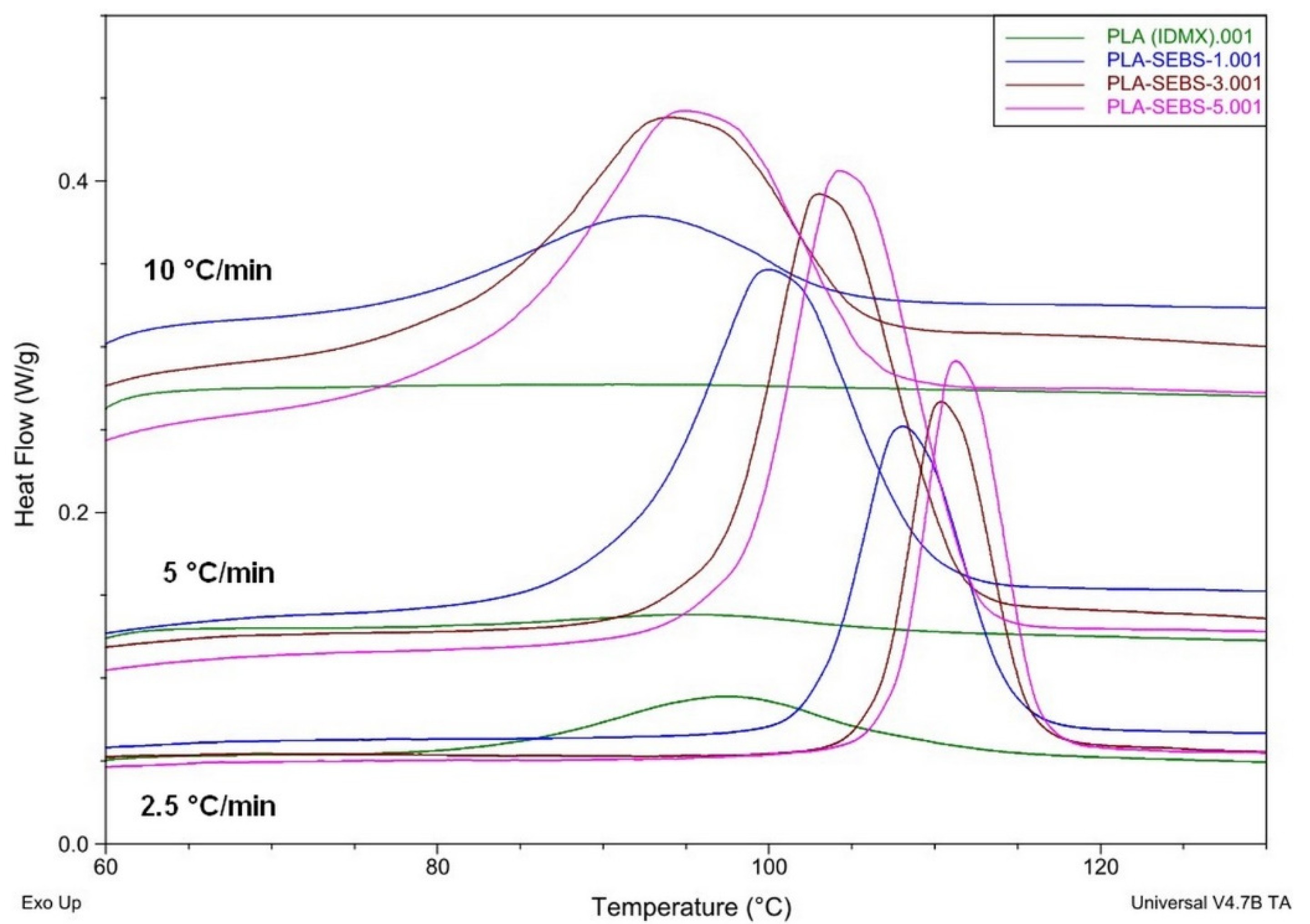
Figure 1 shows the results of the non-isothermal analysis, the effect of cooling rates on crystallization DSC curves at 0, 1, 3 and 5% SEBS contents. The samples are depicted in different colors.
The results of the anisothermal DSC analysis performed on the extruded fibers depict that as the cooling rates increased, the crystallization shifted to a lower temperature and the crystallization interval also widened. In PLA, the crystallization peak appeared clearly only at the slowest cooling rate, but its size was not significant compared to the others. As a result of SEBS, the crystallization peaks became clearly visible at each cooling rate, and as the SEBS content increased, the shape of the curves also changed, suggesting an alteration in the crystal structure. To demonstrate the nucleating effect of SEBS, the increase in the initial temperature of crystallization and in the heat of crystallization must be investigated.
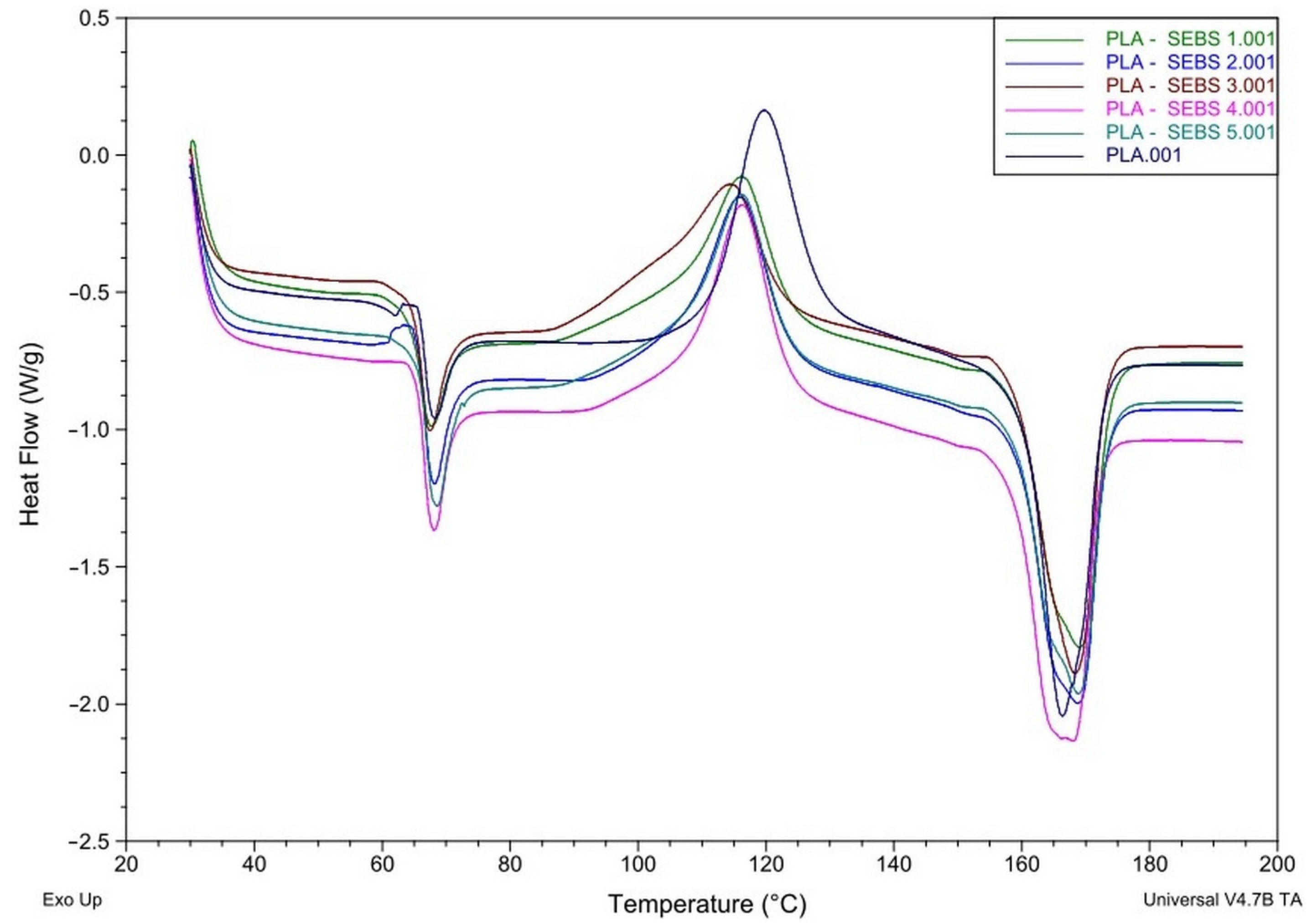
DSC analysis on the printed specimens shows that the cooling during printing was so fast for the PLA that it was able to generate only a few crystalline phases (Figure 2). On the other hand, when it absorbed the heat from the heating, and passed through the glass transition temperature, the phenomenon of so-called cold crystallization started, i.e., the molecules began to rearrange, forming the missing crystalline phases. However, on further heating, melting occurred, where both the crystals originally formed and those formed during the heating melted. The analytical program subtracted the heat of cold crystallization from the heat of melting to obtain the number of crystals that the printed specimens had. The amount of crystalline phases has a serious effect on the mechanical properties of the finished product. The more crystals are formed, the higher the mechanical strength can be achieved, but the impact resistance decreases. In contrast, a decrease in the number of crystallites results in lower mechanical strength but better impact resistance. In the DSC curves obtained during melting, the peak represents the melting temperature of most crystals. During crystallization, the peak means reaching the maximum of the crystallization rate. In Figure 2, the heating rate was 20 °C/min. Figure 2 shows another peak around 60–70 °C, too. This area is the glass transition temperature of PLA; the peak here means the disappearance of the internal stress.
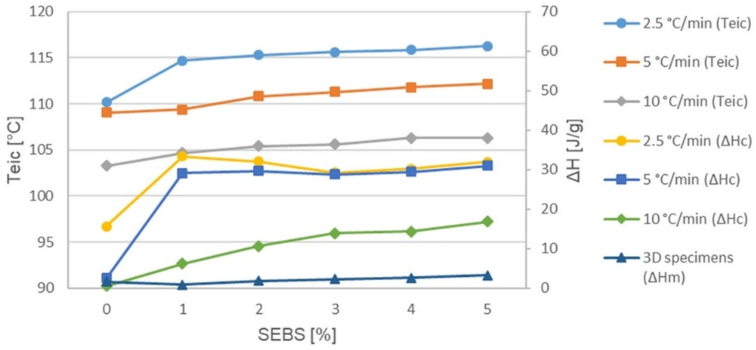
Figure 3 depicts the change in the initial extrapolated temperature of crystallization and the enthalpy changing as a function of SEBS content. According to ISO 11357-1, ‘eic’ is the extrapolated initial temperature of crystallization, which is the intersection of the extrapolated linear section of the rising peak with the apparent baseline below the peak. The enthalpy changing shows the heat of crystallization on the fibers, and the corrected heat of melting on the printed specimens. The samples are depicted in different colors.
The change in the initial extrapolated temperature of crystallization occur on all cooling rates, which precludes the influence of cooling rate. It can be seen that increasing the SEBS content increases the initial crystallization temperature, and crystallization begins sooner at higher temperatures, which is one of the accepted proofs of nucleation [19,20,21,22,23,24,25,26,27,28].
As a result of the appearance of SEBS, the heat of crystallization increased at all cooling rates relative to PLA. A higher heat of crystallization means more crystalline phases. At the two slower cooling rates, although the SEBS content increases, the value of the heat of crystallization does not alter, but the shape of the curve changes (Figure 1). That is, as the initial temperature increases, the shape of the curve alters but the heat of crystallization does not, so it can be concluded that it is likely that crystallites of similar sizes but different shapes, increasingly perfect, will form. At a cooling rate of 10 °C/min, the cooling intensity is already so high that it inhibits the amount of crystals that can be formed, so it does not reach the values measured at slower rates. However, in this case, increasing SEBS content can somewhat compensate the effect of the rapid cooling and increase the number of crystallites formed.
The heat of melting of the sample containing 1% SEBS is lower than that measured at PLA, and the value of 2% is practically the same. The growth of crystalline phases starts from 3%, but the differences are not too large. The sample of 5% reaches twice the heat of melting of PLA. However, the measured heat of melting of 1–3 J/g is quite low compared to 30–35 J/g measured in the non-isothermal test, so it can be said that although SEBS behaves as a nucleating agent, the mixtures are practically amorphous due to the cooling conditions of the printing.
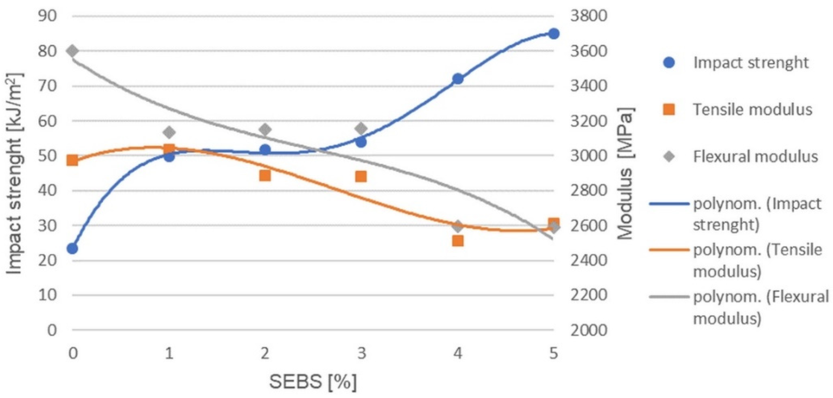
Figure 4 shows the change in impact strength, the tensile modulus and the flexural modulus as a function of SEBS content.
Already, with the addition of 1% SEBS, the impact strength doubles. The growth is minimal between 1 and 3%, practically unchanged; for 4%, it starts to increase further, where it reaches three times the impact strength of the original PLA, and at 5% it is an even higher value. Thanks to the flexibility of SEBS, it absorbs impact energy, thus improving its impact resistance of the originally brittle PLA. Until 3%, the amount is so small that the SEBS particles are at a great distance from each other so that each can locally relieve an internal tension of a small area. The amount may be 4% when the mixture already contains enough SEBS that the spreading impact energy collides into another energy-absorbing SEBS particle. From 4%, the regions of action of SEBS particles can be linked to PLA chains that act as binding molecules, similar to amorphous molecules that bind crystals. Thanks to these overlaps, the energy absorbing effect is amplified and extended.
The tensile modulus is practically unchanged until 3% SEBS is added if the standard deviations are taken into account. The 4 and 5% are also nearly the same, but their values are already lower than the values of the original PLA or the 1–3% samples. Adding a small amount of SEBS improves the impact strength but does not reduce the tensile modulus. During the impact test, the specimen receives the full load immediately, while during the tensile test, the software calculates the tensile modulus according to the standard, from the initial stage of the pull (0.05–0.25%), when the load only begins to build up. At this stage, the amount of SEBS has not yet reached the level to influence the original tensile modulus of the PLA. The change occurs only for a SEBS content of 4% or more.
The flexural modulus decreases slightly with the addition of 1% SEBS but does not change up to 3%, remaining broadly constant. The values of 4 and 5% are also about the same, but even lower. The bending modulus also applies to the initial phase of the load, but here the stress is different; here, tensile and compressive stresses occur simultaneously at the two edges of the specimen. Additionally, while the original modulus value of PLA has been retained in the tensile test, a smaller value is obtained at bending. However, the differences are similar, with 1–3 and 4–5% separated.
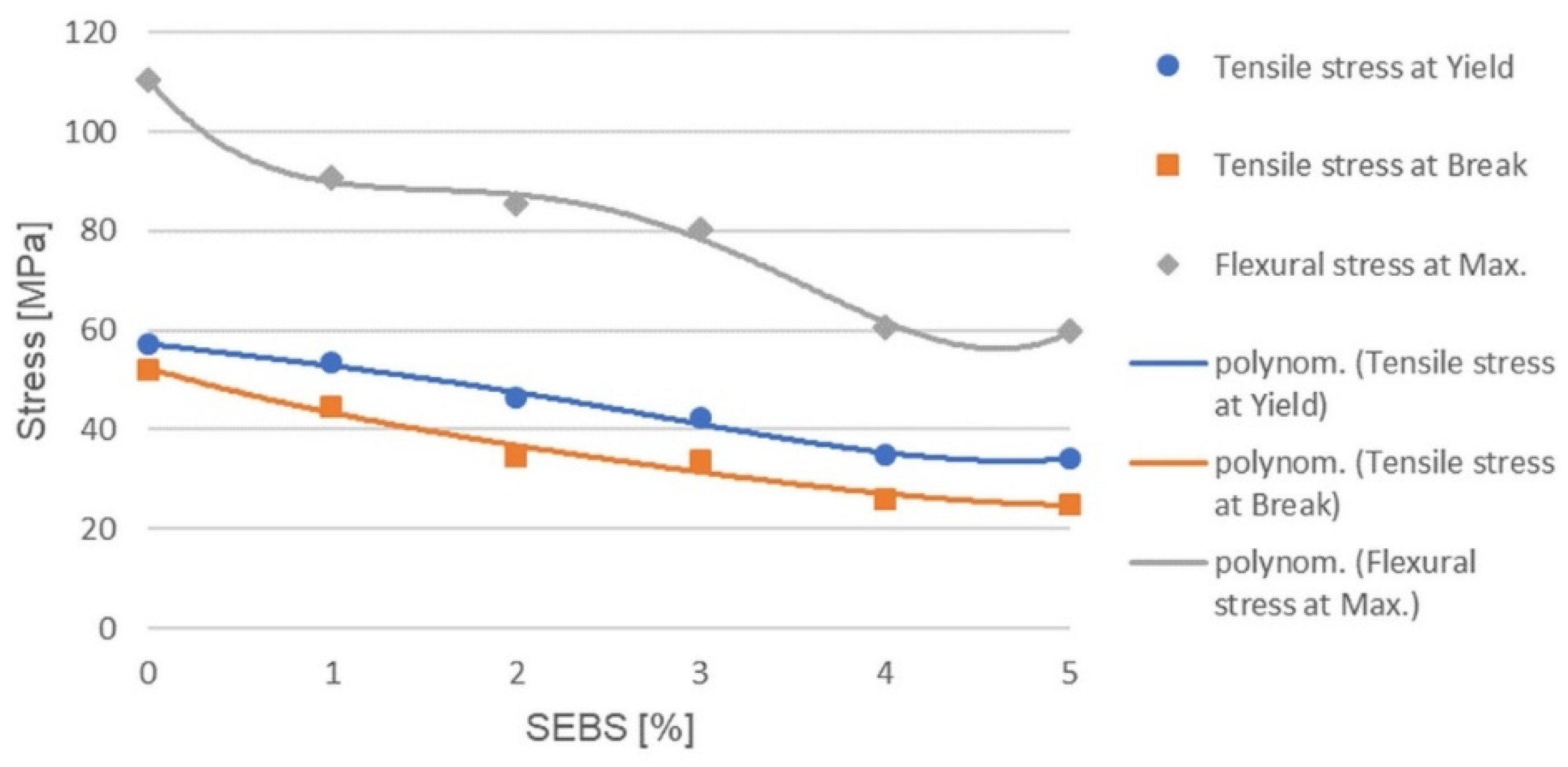
During the tensile test, the PLA behaves in a brittle manner, and even 1% of the SEBS can change this because the neck appears and begins to extend (Figure 5). The elasticity and low strength of SEBS also affect the strength of the mixture. The amount of the thermoplastic elastomer increases, and the tensile stress at Yield decreases. The decline lasts until 4%, then the 4 and 5% samples are similar. For PLA, the tensile strength was plotted.
In the case of the tensile stress at break, a similar statement can be made as in the case of tensile stress at Yield, with the difference that three separate parts can be observed here. The tensile stress at break of PLA decreases slightly with the addition of 1% SEBS. The values of 2 and 3% are smaller but very similar. The tensile strength of the 4 and 5% samples is even lower, but they also show approximately the same values.
The addition of 1% SEBS to PLA increases the impact strength, does not reduce the tensile modulus, and only slightly reduces the tensile stress at break. However, 2 or 3% SEBS further increases the impact strength and does not reduce the tensile modulus but already reduces the tensile stress at break to a greater extent. In the case of 4 or 5% SEBS, even if the impact strength increases even more, the tensile modulus decreases and the tensile stress at break decreases by about half.
In the case of the bending test, one of the changes was also that while the brittle PLA was broken, the samples containing SEBS no longer broke or only partial fracture occurred. The flexural strength is thus the maximum flexural stress for mixtures. The blended SEBS grains can elongate on the drawn side and compress on the compressed side due to their flexibility, thus reducing the strength values. As the amount of SEBS increases, the flexural strength gradually decreases until 4%, and then 5% is practically the same as the 4% sample.
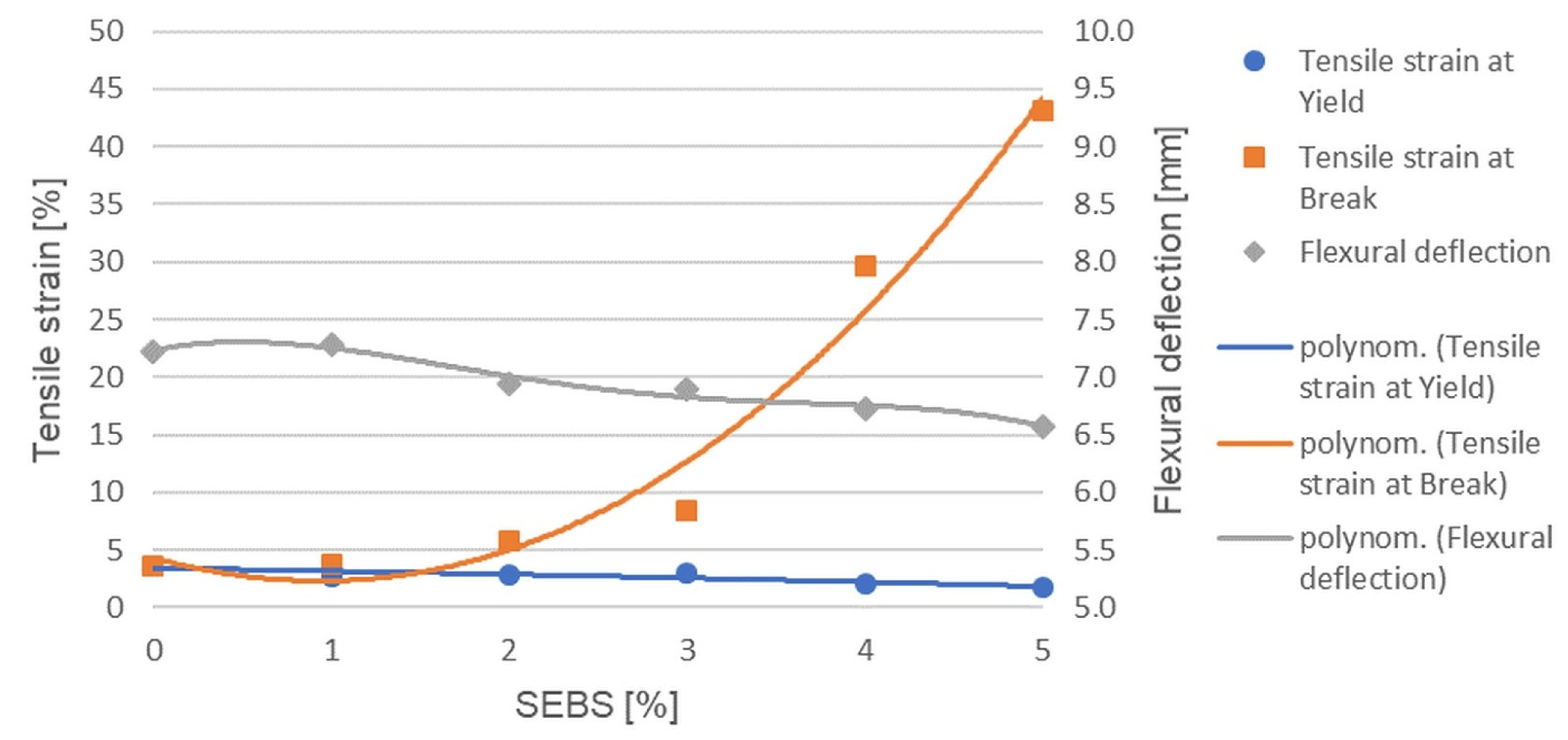
In the case of the tensile strain at Yield, it can be seen that 1–3% and 4–5% are separated from each other (Figure 6). Although the tensile stress at Yield continuously decreased until 3%, the tensile strain at Yield did not change, remaining at nearly the same value. At 4 and 5%, when the lower strength was associated with less elongation, the forming of the neck started earlier. In the case of PLA, the tensile strain at break was also shown here, due to its brittle behavior.
In the case of the tensile strain at break or elongation at break, the value of the 1% sample is practically the same as the PLA, but the rupture of the 2 and 3% samples also occurs, only with a slightly higher elongation. The larger change occurs from 4%, where the elongation at break increases severalfold. From 5%, we can measure even higher values. Until 3%, the amount of SEBS mixed is not large enough to form continuous areas; it can be too scattered, and thus only locally, around itself, can it initiate the rearrangement of PLA molecules in the direction of pull—no large elongations are possible. From 4%, the regions of action of SEBS particles can be linked with PLA binding molecules, which can lead to much higher elongations.
The flexural deflection measured when the maximum stress is reached practically changes only tenths of a millimeter, and if the standard deviation is taken into account, the change cannot be said to be significant. However, in the case of the mean values, it can be noted that the 1% sample is the same as the PLA, followed by a continuous decrease.
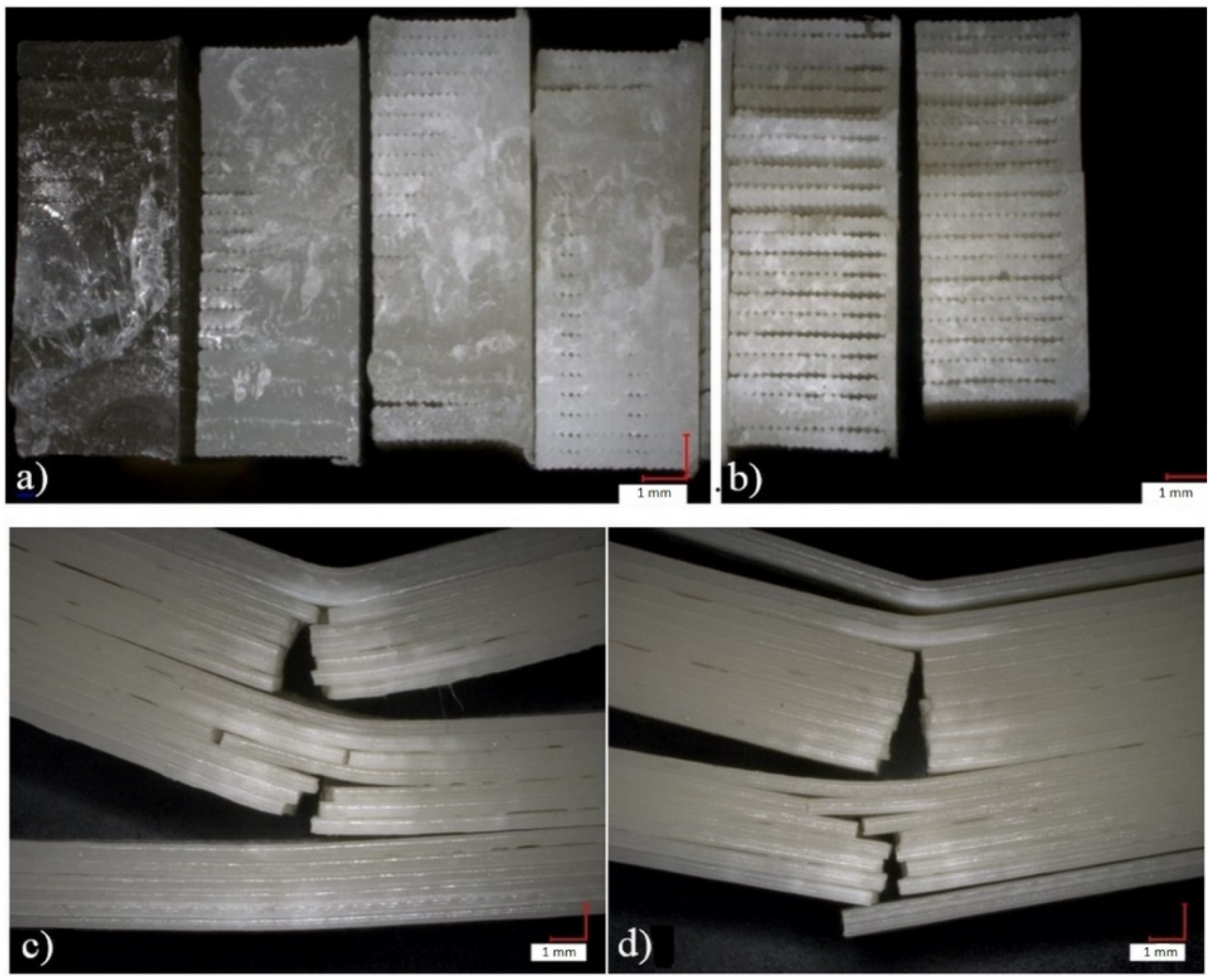
Figure 7 depicts optical microscopic images of the impacted specimens at 20× magnification. Figure 7a,b show the fractured surfaces and Figure 7c,d show the side views of the partial fractures of the unbroken specimens.
The microscopic images show that the fracture surfaces of the printed specimens are quite similar up to 3% SEBS content, and at 4 and 5%, the separation of the fibers can be observed (Figure 7). From PLA until 3%, the entire cross-section of all specimens was broken, while at 4 and 5%, some partial fractures (shown in Figure 7c,d) also occurred. These partial fractures can occur due to the separation of the fibers. The larger parts that remain together break, while the independent, thin fibers become flexible and no longer break due to the higher SEBS content.
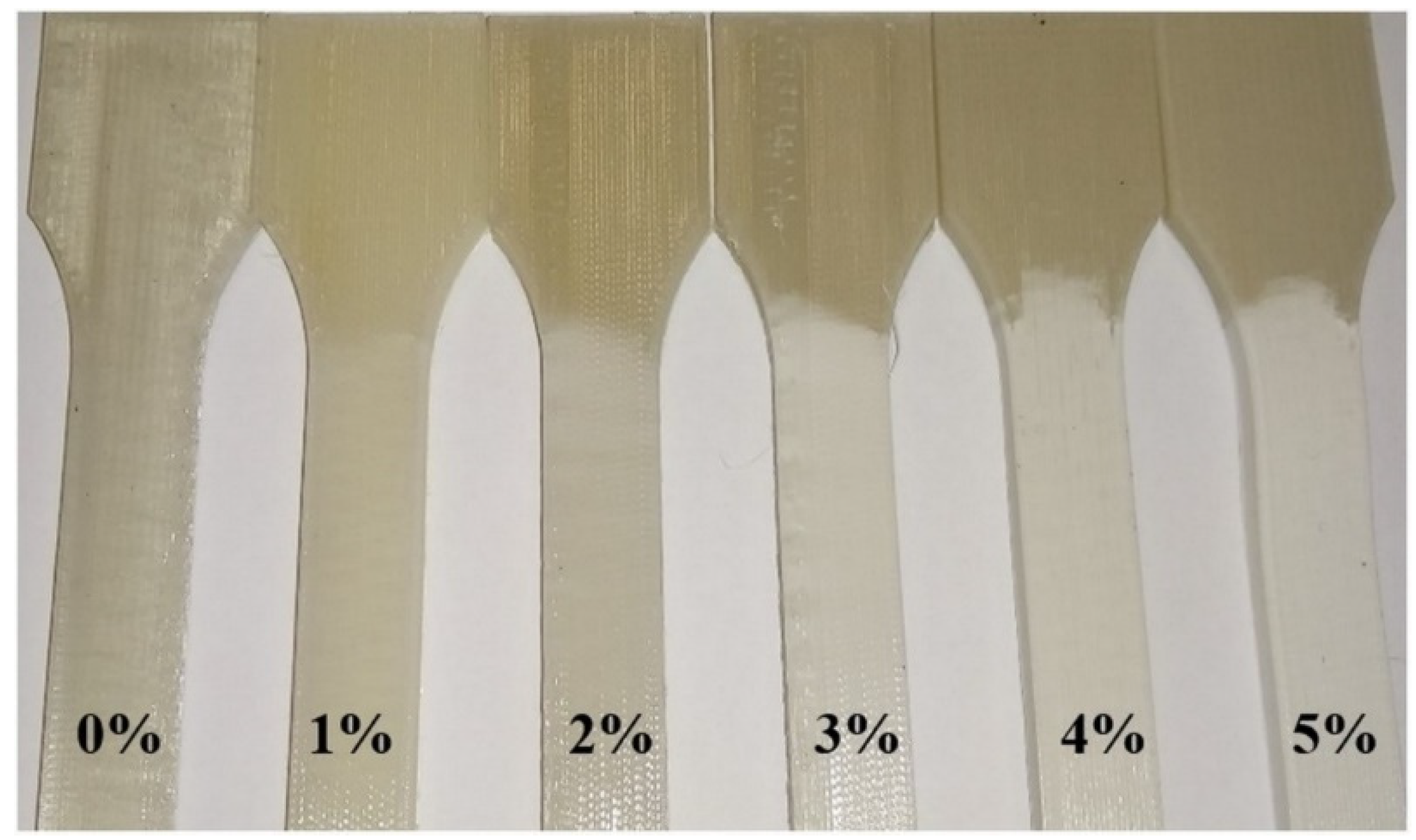
On the broken specimens, bleaching can be observed, which is characteristic of the tensile test of polymers, and it means that micro-cracks are formed under the effect of tensile stress (Figure 8). Now, these micro-cracks travel along the entire length of the specimens, up to the clamping, even at 1% SEBS content. As the concentration of SEBS increases, the specimen appears to become increasingly whiter, i.e., the amount of micro-cracks in the samples increases.
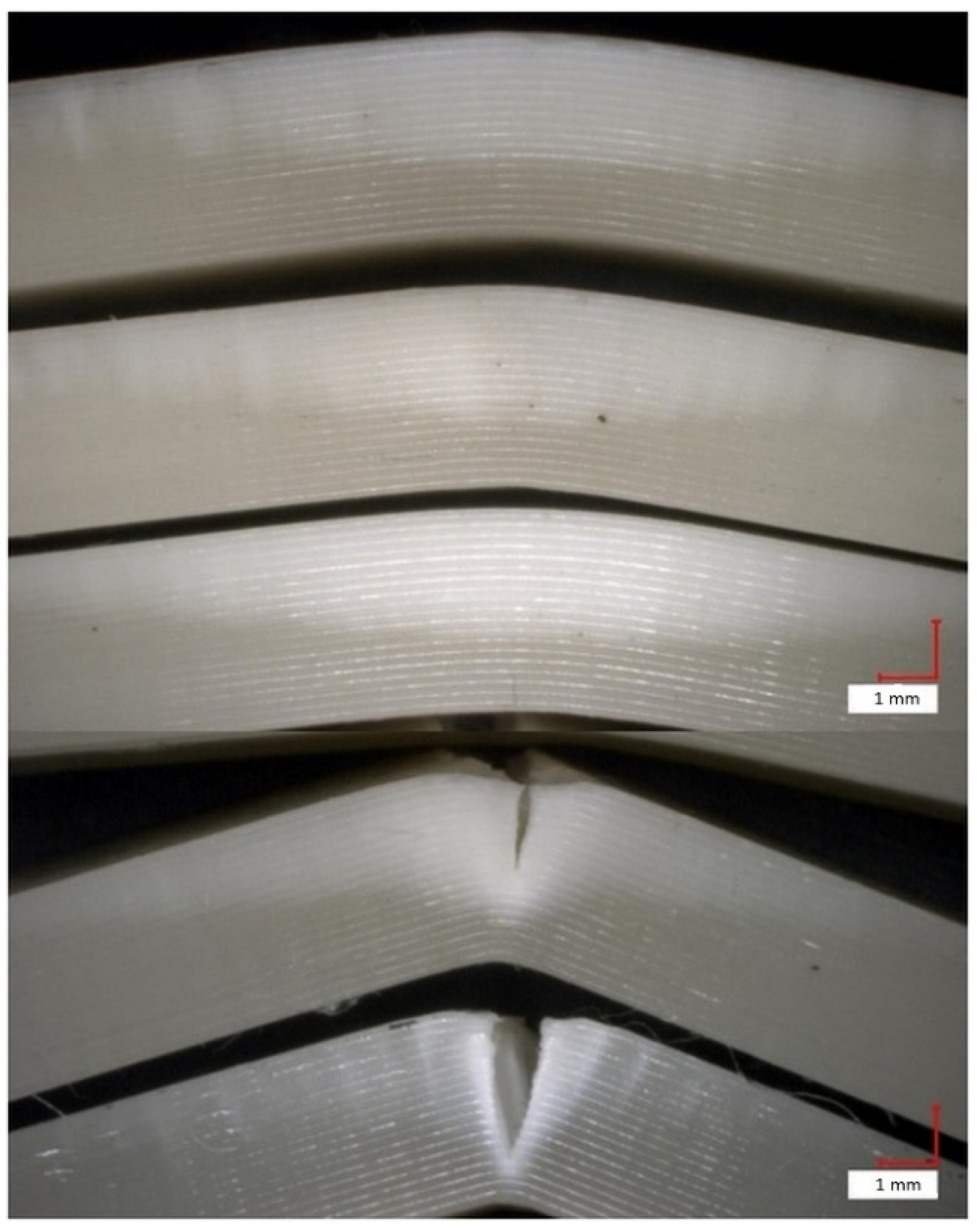
Figure 9 shows that in the case of 1 and 2% SEBS, the samples suffer from a partial fracture. At 1%, most of the cross-section breaks, at 2%, the fracture surface is already visibly reduced, and from 3%, fracture of the sample no longer occurs.

3.2. Results of PLA-SEBS-CNT Nanocomposites

From the study of PLA-SEBS blends, it can be concluded that the greatest potential is the blend containing 1% SEBS, because it does not or only slightly reduces the strength values of PLA, while doubling its impact resistance and mixing as little foreign matter as possible to PLA. For this reason, the sample containing 1% SEBS was chosen to mix carbon nanotubes in 0.06 and 0.1%. The conditions for blending, fiber production and printing are the same as those used for PLA-SEBS blends. DSC measurements were performed on the fiber and mechanical tests were performed on the printed specimens (Figure 10).
The labeling of the samples has been simplified, always containing only the name of the last additive, so that in the following, the names of the four samples examined are PLA, 1% SEBS, 0.06% CNT and 0.1% CNT.
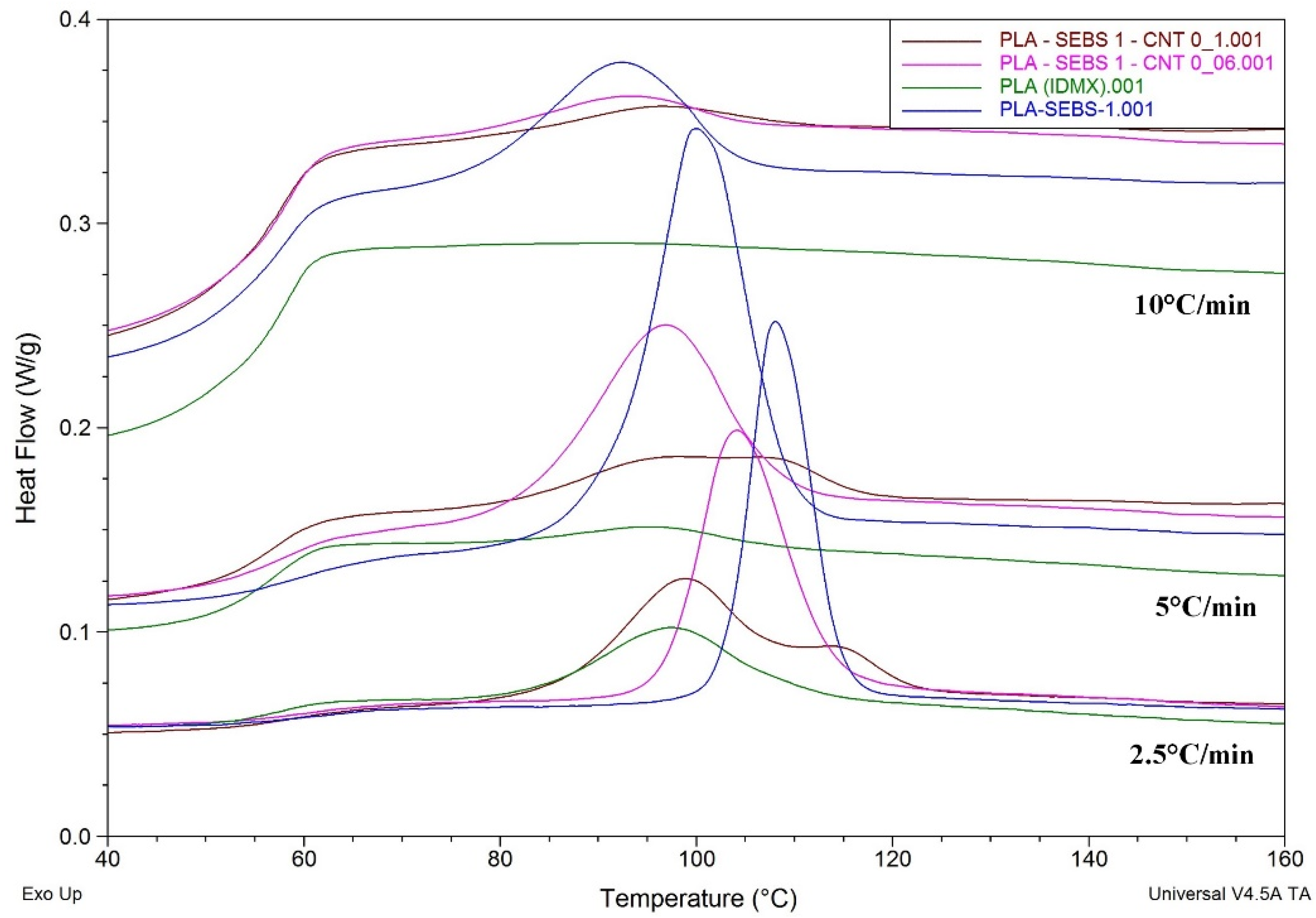
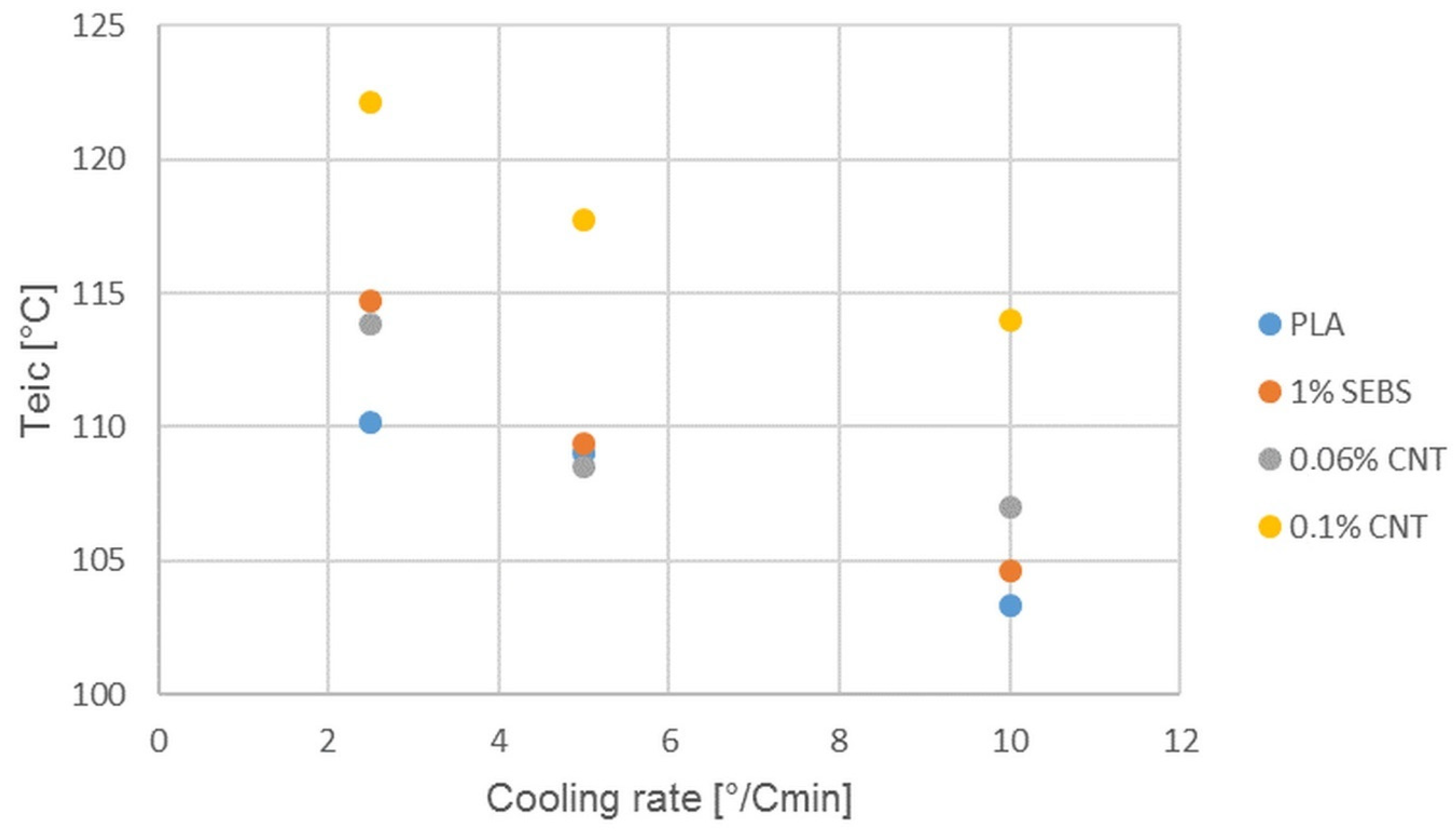
Examining the DSC curves of the nanocomposites, it can be said that the initial temperatures of crystallization (
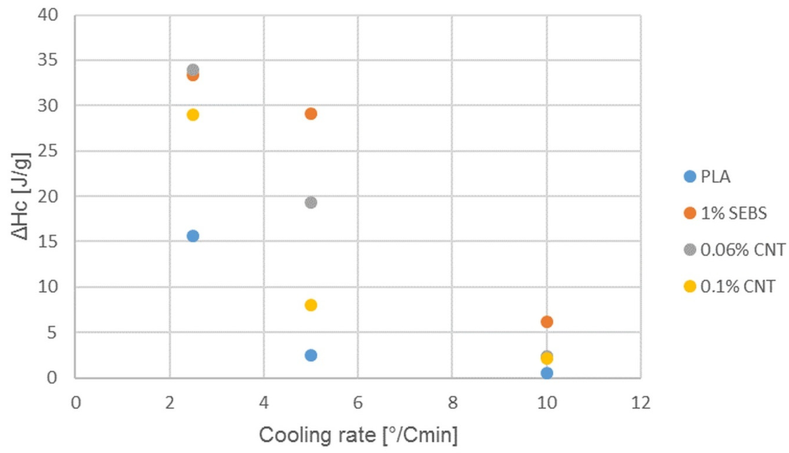
Figure 11) increase with increasing CNT content, which is evidence of nucleation. Thus, crystallization begins earlier, but the heat of crystallization (Figure 12) does not increase, which is likely to mean a modification of the crystal structure. The two peaks in the 0.1% CNT crystallization curve refer this. The first peak, as it precedes SEBS nucleation, is clearly the crystal structure formed by CNT.
The heat of crystallization may also have been reduced because SEBS has been shown to be a good nucleating agent, so that at higher cooling rates, the addition of CNT rather inhibits the nucleation of SEBS. There is too much nucleating agent while less time is available for crystallization, so too much growing crystallite inhibits each other. In the case of slow cooling, however, it is possible to prevail the positive effect of carbon nanotubes.
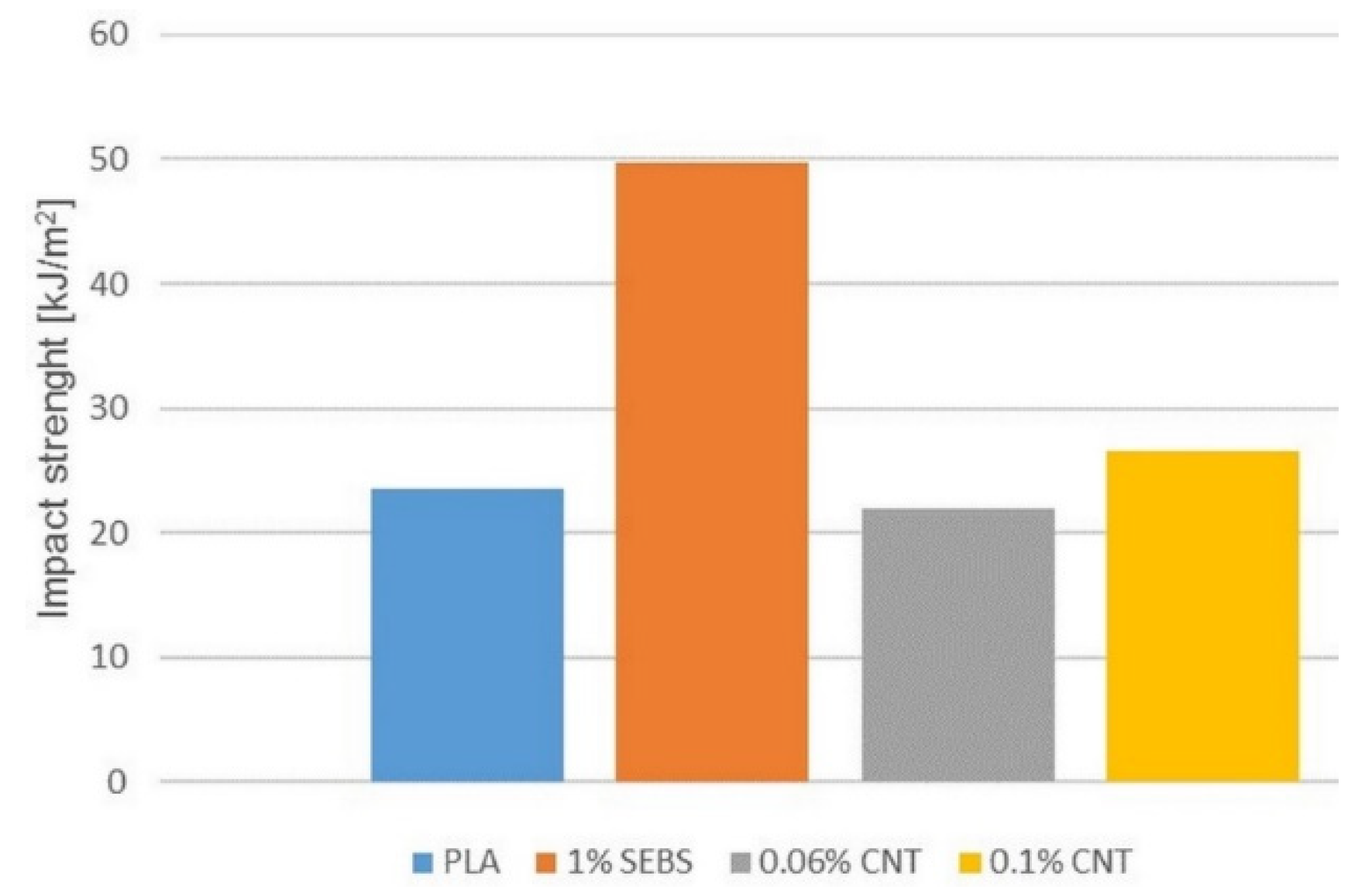
Figure 13 depicts the results of the Charpy impact testing of nanocomposites compared to the original PLA and 1% SEBS sample. Comparing the results of the nanocomposites with the original PLA and the samples containing 1% SEBS, it can be seen that the impact strength of the PLA doubled under the influence of SEBS and then decreased back to its original value when CNTs were added. Increasing the content of CNTs slightly increased the impact strength (Figure 13). However, looking at Figure 14, it is important to note that both PLA and 1% SEBS samples were broken in their full cross-section during the study. The direction of fracture was perpendicular to the longitudinal axis of the specimen. In contrast, for samples containing CNTs, only partial fiber separation occurred, or the fracture traveled longitudinally along the specimen and not perpendicularly. The magnitude of the force acting on the specimens did not reach the energy required for complete fracture but was large enough to cause a slight permanent deformation, and the 0.06% CNT specimens remained in a slightly bent state at the end of the test. For 0.1% CNT samples, the impact energy could cause fiber separation, but the specimens almost regained their original shape. Numerical values show a decrease, while in reality, the carbon nanotube changes the impact resistance. It is likely that this effect is caused by an improvement in the adhesion of the layer in the impact behavior of the material.
Figure 15, Figure 16 and 
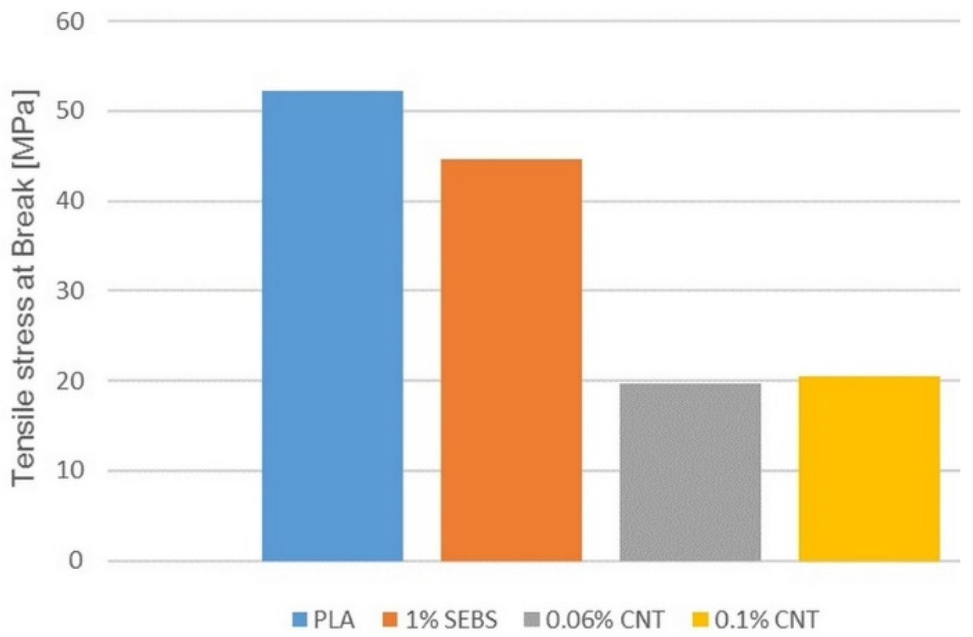
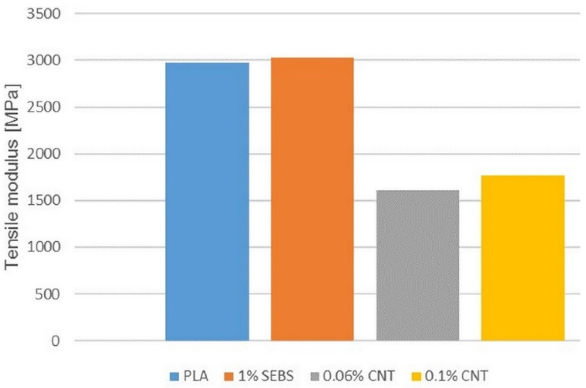
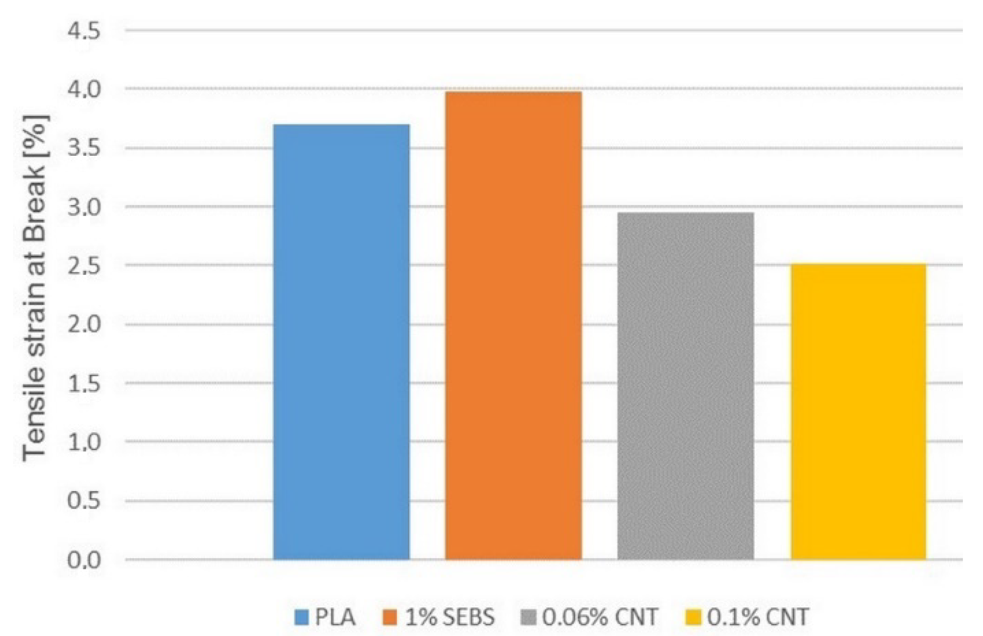
Figure 17 show the results of tensile test, the tensile modulus and the tensile strength and the elongation at break.
The results of the tensile test show that with the addition of carbon nanotubes, the results decrease. The tensile modulus and the tensile strength are halved, and the elongation at break is slightly reduced. However, visual inspection of the torn specimens shows (Figure 18) that the PLA and 1% SEBS specimens broken along a line in the full cross-section, perpendicular to the longitudinal axis, while the CNT-containing specimens again show fiber separation and there is no well-defined fracture line. The reason for the decrease in values may be the separation of the fibers, which can be prevented or reduced by changing the printing parameters; for example, by raising the printing temperature. These are the subject of further investigation.
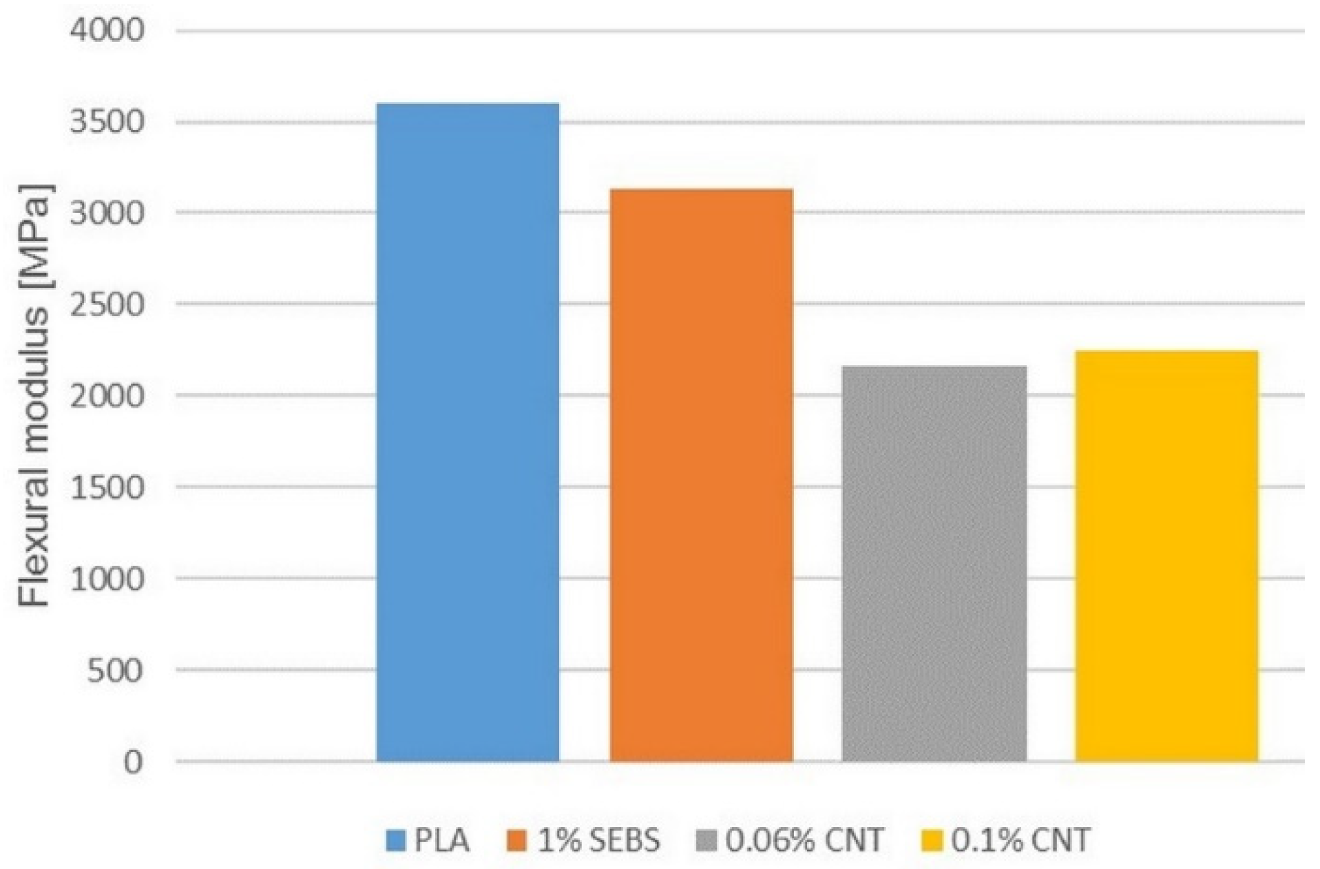
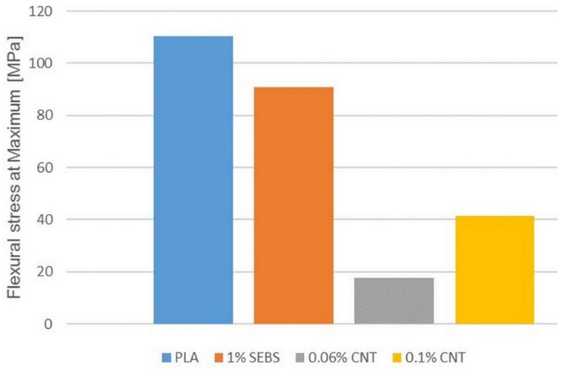
Figure 19, Figure 20 and 
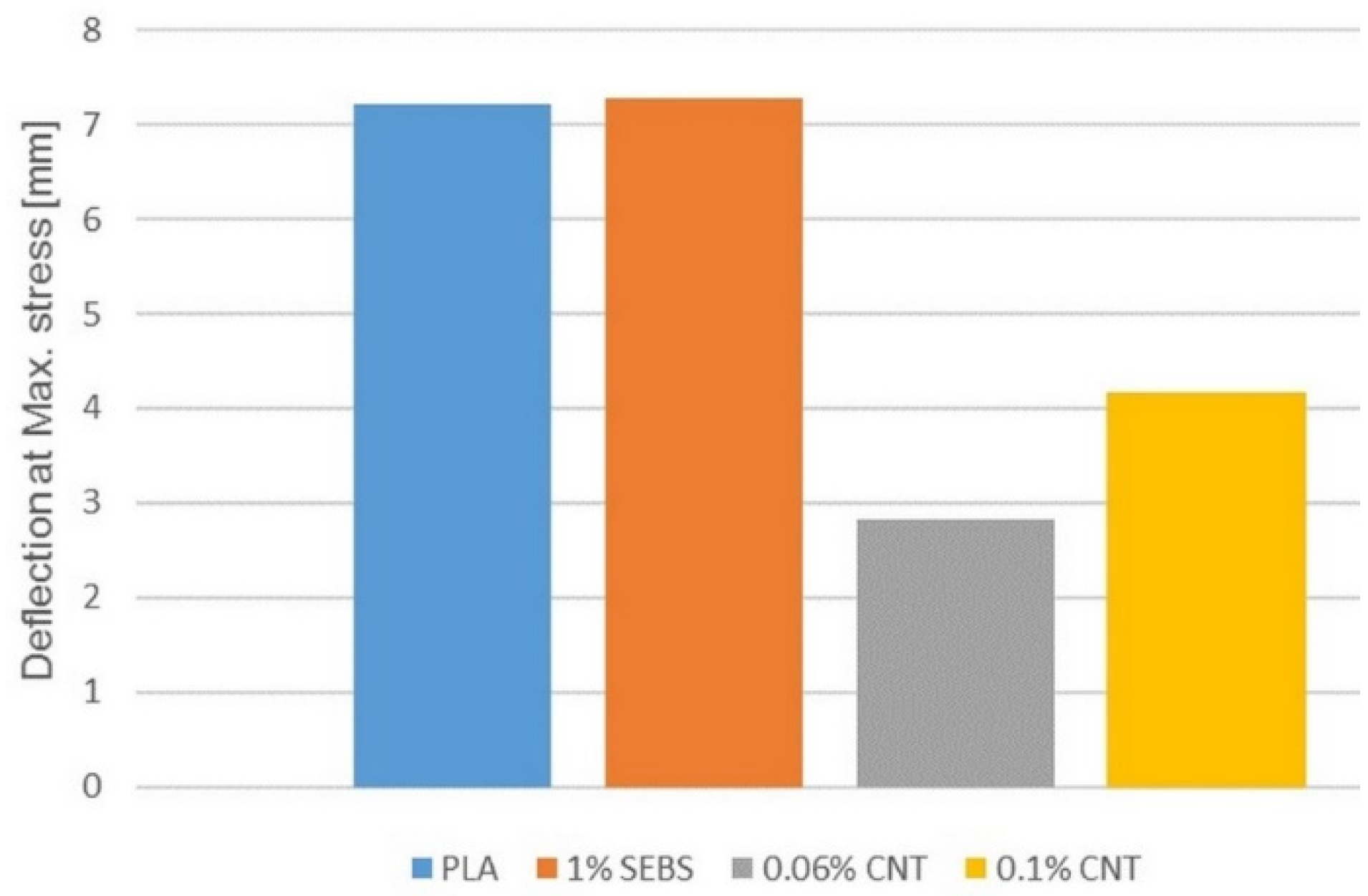
Figure 21 show the results of bending test, the flexural modulus, the flexural stress at maximum and the deflection at maximum stress.
The change in the results of the bending test is similar to that observed in the tensile test. The values decrease in all cases of the flexural modulus, the maximum flexural stress and the deflection at the maximum stress. The 1% SEBS sample shows lower values compared to the original PLA and the values further decrease if the CNTs are also mixed into it. Increasing the carbon nanotube content slightly increases the values but is still lower compared to samples with pure PLA or 1% SEBS.
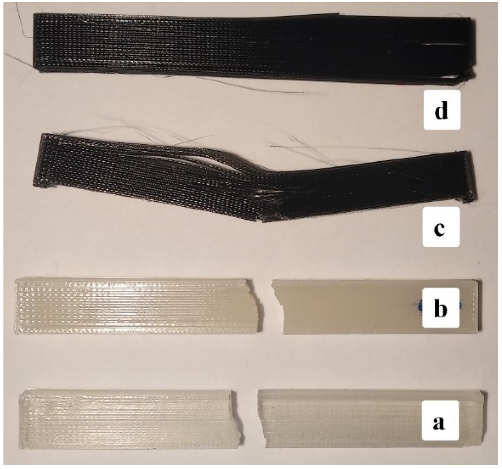
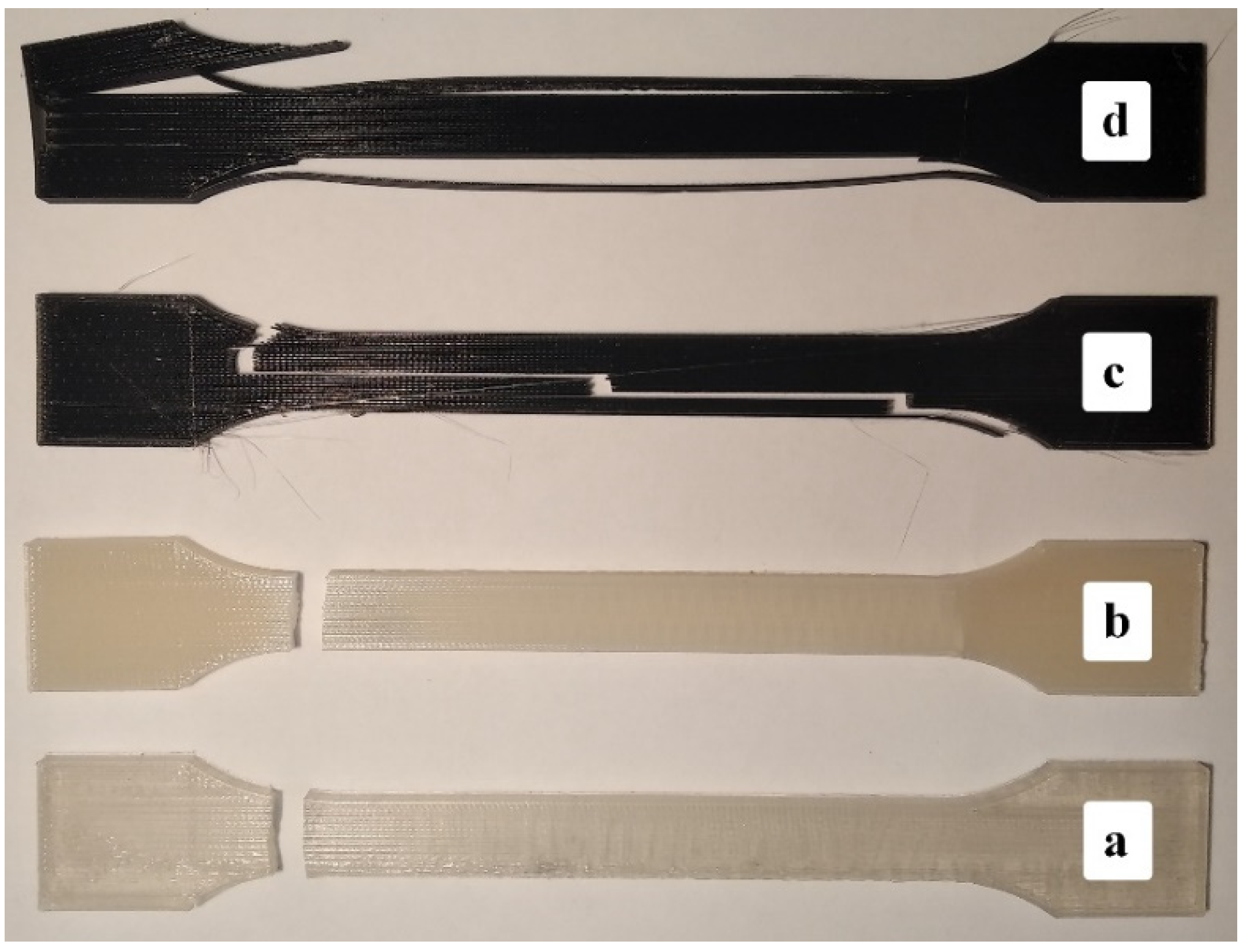
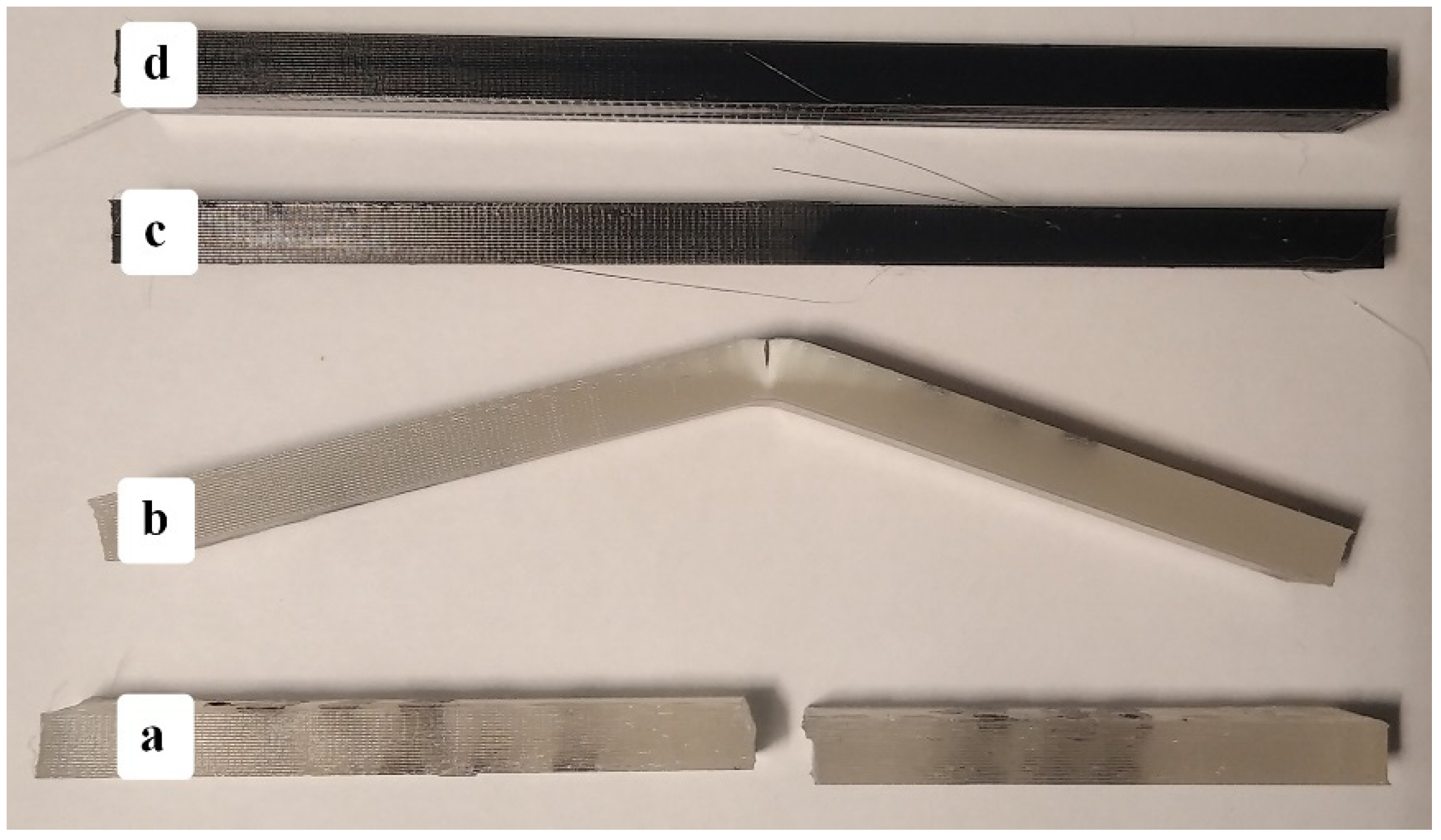
However, if we look at the specimens after the test (Figure 22), we can see that the pure PLA was broken in the full cross-section, the 1% SEBS sample suffered partial fracture, but the samples containing different amount of CNTs did not fracture. In addition, not only did they not break, but they also did not suffer a partial fracture, and they almost completely regained their straight shape after the test. The same cannot be said for the 1% SEBS sample, as it suffered from permanent deformation and remained in its bent state.
The type of test is three-point bending, which means that the specimens are not fixed anywhere and can move freely. The free movement of the specimens made it possible to show that the carbon nanotube increases the degree of elastic deformation, pushing out the occurrence of residual deformation. In the case of a tensile test, the fixed grip and the test method lasting until complete failure prevented its detection.
However, this also indicates that the resulting flexural stress value is not a strength value but only a limit stress, and this limit stress is still less than the stress required for the residual deformation.
This means that PLA samples reinforced with 0.06 and 0.1% carbon nanotubes and containing 1% SEBS are not only able to withstand a high degree of bending stress but can also be said to be raw materials suitable for shape memory prototypes or product printing.

4. Conclusions

From 1 to 5% SEBS thermoplastic elastomer was mixed to PLA, and then the printed specimens were subjected to thermal, mechanical, and optical observations.
DSC studies on the printing fiber have shown that SEBS can act as a nucleating agent in PLA by increasing the initial crystallization temperatures regardless of the cooling rates. However, studies on printed specimens have shown that cooling during the printing is so rapid for PLA that it can only produce a minimal crystalline phase, and although the nucleating effect of SEBS can be demonstrated, the amount of crystallites formed is too small to affect the mechanical properties.
In the case of an impact test, the impact strength doubles as early as the addition of 1% SEBS and does not change up to 3%. From 4%, partially broken specimens also occur.
In the case of tensile testing, the tensile modulus does not change up to 3% SEBS, and from 1%, the phenomenon of neck formation appears, and the elongation of the initially brittle PLA begins. The tensile stress at Yield and tensile strength of the specimens decreased only slightly in the case of the 1% sample, and the values of 4 and 5% were practically the same. In the case of the elongation at break, the increase is small until 3%, and there is a higher change from 4%, where the SEBS content reaches the value where the regions of action of SEBS particles can be connected to PLA chains. The whitening of the drawn specimens, that is, the number of micro-cracks, increased continuously with increasing SEBS concentration, but even at 1%, it went along the entire length of the specimen.
In the bending test, the flexural modulus decreased only slightly, then practically did not change between 1–3%, and 4–5% also took almost the same but lower values. During bending, only the PLA broke in a brittle manner, 1–2% SEBS containing samples were partially broken, and from 3%, the specimens were no longer broken, but only bent. The flexural strength decreased slightly but continuously until 4%, with 5% almost equaling with 4%. The values of deflection measured when the maximum stress was reached were not affected by the SEBS content.
In summary, the mechanical tests revealed that in most cases, 1–3% and 4–5% were separated. In all probability, up to 3%, the amount of mixed SEBS is so small, so scattered, that it can dampen the internal tension only at the local level, in its immediate vicinity. From 4%, these damping fields overlapped, connected with PLA chains, thus amplified and extended each other’s effect.
Thermal studies of the nanocomposites showed that 0.1% CNT was able to modify the crystal structure, and two-peak crystallization became visible on the DSC curves, of which the first peak is clearly the effect of CNT as it precedes SEBS-induced crystallization.
In mechanical tests, the reduction in numerical data can be misleading at first glance, especially as it occurs in all studies. The visual inspection of the specimens after testing reveals that CNT increases the impact and bending resistance of the PLA-SEBS blend. While pure PLA and the PLA-1% SEBS blend was broken during the Charpy test, the two nanocomposites were only partially broken or cracked, and the specimens suffered only minor residual deformation. At 0.06% CNT, the samples remained in a slightly bent state, and at 0.1% CNT, they almost regained their original shape.
In the bending test, it was found that the pure PLA was completely broken, and the 1% SEBS mixture also suffered a partial break and remained in a bent position at the end of the test. However, the nanocomposites not only did not break, but they did not suffer a partial break, and moreover, almost completely regained their original shape. The carbon nanotube reinforces the mixture to such an extent that the stress during the test does not reach the value causing the residual deformation. During the test, only elastic deformation occurs in the specimen, which is reversed after the load has been removed.
As the amount of blended carbon nanotube is very small, the obtained results confirm that the mixing quality was adequate, and the carbon nanotube was properly distributed in the fiber during extrusion. It can also be said that PLA blends containing 1% SEBS and 0.06 or 0.1% CNTs are suitable as raw materials for the 3D printing of shape memory products or prototypes.

Author Contributions

Conceptualization, Z.W. and B.Á.; methodology, B.Á.; investigation, B.Á.; resources, Z.W.; data curation, B.Á.; writing—original draft preparation, B.Á.; writing—review and editing, Z.W.; supervision, Z.W. All authors have read and agreed to the published version of the manuscript.

Funding

This work was supported by the European Union, co-financed by European Social Fund (Grant No. EFOP-3.6.1-16-2016-00014).

Institutional Review Board Statement

Not applicable.

Informed Consent Statement

Not applicable.

Acknowledgments

This work was supported by the European Union, co-financed by European Social Fund (Grant No. EFOP-3.6.1-16-2016-00014).

Conflicts of Interest

The authors declare no conflict of interest. The funders had no role in the design of the study; in the collection, analyses, or interpretation of data; in the writing of the manuscript, or in the decision to publish the results.

References

  1. Ngo, T.D.; Kashani, A.; Imbalzano, G.; Nguyen, K.T.Q.; Hui, D. Additive manufacturing (3D printing): A review of materials, methods, applications and challenges. Compos. Part B Eng. 2018, 143, 172–196. [Google Scholar] [CrossRef]
  2. Bose, S.; Ke, D.; Sahasrabudhe, H.; Bandyopadhyay, A. Additive manufacturing of biomaterials. Prog. Mater. Sci. 2018, 93, 45–111. [Google Scholar] [CrossRef] [PubMed]
  3. Murariu, M.; Dubois, P. PLA composites: From production to properties. Adv. Drug Deliv. Rev. 2016, 107, 17–46. [Google Scholar] [CrossRef] [PubMed]
  4. Lim, L.-T.; Auras, R.; Rubino, M. Processing technologies for poly(lactic acid). Prog. Polym. Sci. 2008, 33, 820–852. [Google Scholar] [CrossRef]
  5. Saeidlou, M.A.; Huneault, H.; Li, C.B. Park: Poly(lactic acid) crystallization. Prog. Polym. Sci. 2012, 37, 1657–1677. [Google Scholar] [CrossRef]
  6. Anderson, K.S.; Schreck, K.M.; Hillmyer, M.A. Toughening Polylactide. Polym. Rev. 2008, 48, 85–108. [Google Scholar] [CrossRef]
  7. Notta-Cuvier, D.; Odent, J.; Delille, R.; Murariu, M.; Lauro, F.; Raquez, J.; Bennani, B.; Dubois, P. Tailoring polylactide (PLA) properties for automotive applications: Effect of addition of designed additives on main mechanical properties. Polym. Test. 2014, 36, 1–9. [Google Scholar] [CrossRef]
  8. Shih, Y.-F.; Huang, C.-C.; Chen, P.-W. Biodegradable green composites reinforced by the fiber recycling from disposable chopsticks. Mater. Sci. Eng. A 2010, 527, 1516–1521. [Google Scholar] [CrossRef]
  9. Liao, H.-T.; Wu, C.-S. Preparation and characterization of ternary blends composed of polylactide, poly(ɛ-caprolactone) and starch. Mater. Sci. Eng. A 2009, 515, 207–214. [Google Scholar] [CrossRef]
  10. Su, S.; Kopitzky, R.; Tolga, S.; Kabasci, S. Polylactide (PLA) and Its Blends with Poly(butylene succinate) (PBS): A Brief Review. Polymer 2019, 11, 1193. [Google Scholar] [CrossRef] [Green Version]
  11. Phattarateera, S.; Pattamaprom, C. Comparative performance of functional rubbers on toughness and thermal property improvement of polylactic acid. Mater. Today Commun. 2019, 19, 374–382. [Google Scholar] [CrossRef]
  12. Petchwattana, N.; Covavisaruch, S.; Euapanthasate, N. Utilization of ultrafine acrylate rubber particles as a toughening agent for poly(lactic acid). Mater. Sci. Eng. A 2012, 532, 64–70. [Google Scholar] [CrossRef]
  13. Tsou, C.-H.; Kao, B.-J.; Yang, M.-C.; Suen, M.-C.; Lee, Y.-H.; Chen, J.-C.; Yao, W.-H.; Lin, S.-M.; Huang, S.-H.; De Guzman, M.; et al. Biocompatibility and characterization of polylactic acid/styrene-ethylene-butylene-styrene composites. Bio-Med. Mater. Eng. 2015, 26, S147–S154. [Google Scholar] [CrossRef] [PubMed] [Green Version]
  14. Sangeetha, V.H.; Varghese, T.O.; Nayak, S.K. Toughening of polylactic acid using styrene ethylene butylene styrene: Mechanical, thermal, and morphological studies. Polym. Eng. Sci. 2016, 56, 669–675. [Google Scholar] [CrossRef]
  15. Arvidson, S.A.; Roskov, K.E.; Patel, J.J.; Spontak, R.J.; Khan, S.A.; Gorga, R.E. Modification of Melt-Spun Isotactic Polypropylene and Poly(lactic acid) Bicomponent Filaments with a Premade Block Copolymer. Macromology 2012, 45, 913–925. [Google Scholar] [CrossRef]
  16. Tjong, S.; Xu, S.; Mai, Y. Impact fracture toughness of short glass fiber-reinforced polyamide 6,6 hybrid composites containing elastomer particles using essential work of fracture concept. Mater. Sci. Eng. A 2003, 347, 338–345. [Google Scholar] [CrossRef]
  17. Nehra, R.; Maiti, S.N.; Jacob, J. Effect of Thermoplastic Elastomer on Melt Rheological and Fracture Behavior of Poly(Lactic Acid). Polym. Technol. Eng. 2017, 57, 1254–1264. [Google Scholar] [CrossRef]
  18. Lu, Y.; Wang, C.; Yu, J.; Lu, S. Study on Preparation and Structural Properties of High Toughness Polylactic Acid. IOP Conf. Ser. Mater. Sci. Eng. 2018, 394, 022059. [Google Scholar] [CrossRef]
  19. Raquez, J.-M.; Habibi, Y.; Murariu, M.; Dubois, P. Polylactide (PLA)-based nanocomposites. Prog. Polym. Sci. 2013, 38, 1504–1542. [Google Scholar] [CrossRef]
  20. Papageorgiou, G.; Achilias, D.; Nanaki, S.; Beslikas, T.; Bikiaris, D. PLA nanocomposites: Effect of filler type on non-isothermal crystallization. Thermochim. Acta 2010, 511, 129–139. [Google Scholar] [CrossRef]
  21. Park, S.H.; Lee, S.G.; Kim, S.H. Isothermal crystallization behavior and mechanical properties of polylactide/carbon nanotube nanocomposites. Compos. Part A Appl. Sci. Manuf. 2013, 46, 11–18. [Google Scholar] [CrossRef]
  22. Shi, J.; Lu, X.; Li, H.; Li, D. Isothermal crystallization kinetics and melting behavior of PLLA/f-MWNTs composites. J. Therm. Anal. Calorim. 2014, 117, 1385–1396. [Google Scholar] [CrossRef]
  23. Kuan, C.-F.; Kuan, H.; Ma, C.-C.M.; Chen, C.-H. Mechanical and electrical properties of multi-wall carbon nanotube/poly(lactic acid) composites. J. Phys. Chem. Solids 2008, 69, 1395–1398. [Google Scholar] [CrossRef]
  24. Brzeziński, M.; Biela, T. Polylactide nanocomposites with functionalized carbon nanotubes and their stereocomplexes: A focused review. Mater. Lett. 2014, 121, 244–250. [Google Scholar] [CrossRef]
  25. Wu, C.-S.; Liao, H.-T. Study on the preparation and characterization of biodegradable polylactide/multi-walled carbon nanotubes nanocomposites. Polymer 2007, 48, 4449–4458. [Google Scholar] [CrossRef]
  26. Gnanasekaran, K.; Heijmans, T.; van Bennekom, S.; Woldhuis, H.; Wijnia, S.; de With, G.; Friedrich, H. 3D printing of CNT- and graphene-based conductive polymer nanocomposites by fused deposition modeling. Appl. Mater. Today 2017, 9, 21–28. [Google Scholar] [CrossRef]
  27. Postiglione, G.; Natale, G.; Griffini, G.; Levi, M.; Turri, S. Conductive 3D microstructures by direct 3D printing of polymer/carbon nanotube nanocomposites via liquid deposition modeling. Compos. Part A Appl. Sci. Manuf. 2015, 76, 110–114. [Google Scholar] [CrossRef]
  28. Zhou, X.; Deng, J.; Fang, C.; Lei, W.; Song, Y.; Zhang, Z.; Huang, Z.; Li, Y. Additive manufacturing of CNTs/PLA composites and the correlation between microstructure and functional properties. J. Mater. Sci. Technol. 2021, 60, 27–34. [Google Scholar] [CrossRef]
  29. Chen, P.; Yu, K.; Wang, Y.; Wang, W.; Zhou, H.; Li, H.; Mi, J.; Wang, X. The Effect of Composite Nucleating Agent on the Crystallization Behavior of Branched Poly (Lactic Acid). J. Polym. Environ. 2018, 26, 3718–3730. [Google Scholar] [CrossRef]
  30. Gui, Z.; Lu, C.; Cheng, S. Comparison of the effects of commercial nucleation agents on the crystallization and melting behaviour of polylactide. Polym. Test. 2013, 32, 15–21. [Google Scholar] [CrossRef]
  31. Li, H.; Huneault, M.A. Effect of nucleation and plasticization on the crystallization of poly(lactic acid). Polymer 2007, 48, 6855–6866. [Google Scholar] [CrossRef] [Green Version]
  32. Pukánszky, B.; Belina, K.; Rockenbauer, A.; Maurer, F. Effect of nucleation, filler anisotropy and orientation on the properties of PP composites. Composites 1994, 25, 205–214. [Google Scholar] [CrossRef]
  33. Miyata, T.; Masuko, T. Crystallization behaviour of poly(l-lactide). Polymer 1998, 39, 5515–5521. [Google Scholar] [CrossRef]
  34. Ádámné, M.A.; Belina, K. Crystallization and melting properties of polypropylenes containing multiwall carbon nanotube. AIP Conf. Proc. 2011, 1353, 773–778. [Google Scholar]
  35. Ádámné, M.A.; Belina, K. Preparation and investigation of multiwall carbon nanotube-polymer composites. Int. J. Mater. Form. 2009, 2, 865–868. [Google Scholar] [CrossRef]
  36. Vasanthakumari, R.; Pennings, A. Crystallization kinetics of poly(l-lactic acid). Polymer 1983, 24, 175–178. [Google Scholar] [CrossRef]
  37. Ádámné, A.M.; Belina, K.; Posa, M.; Kecskés, B. Investigation of mechanical and thermal properties of oriented polyamid copolymer. Int. J. Mater. Form. 2008, 1, 587–590. [Google Scholar] [CrossRef]
Figure 1. Effect of cooling rates and SEBS content on crystallization curves.
Applsci 11 06218 g001
Figure 2. DSC curves of the first heating of printed specimens.
Applsci 11 06218 g002
Figure 3. The initial extrapolated temperature of crystallization and the enthalpy changing as a function of SEBS content.
Applsci 11 06218 g003
Figure 4. Impact strength, tensile and flexural modulus as a function of SEBS content.
Applsci 11 06218 g004
Figure 5. Tensile and flexural stress as a function of SEBS content.
Applsci 11 06218 g005
Figure 6. Tensile strain and flexural deflection as a function of SEBS content.
Applsci 11 06218 g006
Figure 7. Microscopic images of fracture surfaces (a,b) and side views of partial fractures (c,d), (a) PLA-1-2–3% SEBS (left to right), (b) 4–5% SEBS (left to right), (c) 4% SEBS, (d) 5% SEBS.
Applsci 11 06218 g007
Figure 8. Photographs of ruptured specimens from PLA to 5% SEBS (left to right).
Applsci 11 06218 g008
Figure 9. Microscopic images of bent specimens (1–5% SEBS from bottom to top).
Applsci 11 06218 g009
Figure 10. Crystallization DSC curves of samples using different cooling rates.
Applsci 11 06218 g010
Figure 11. Initial extrapolated temperature of crystallization.
Applsci 11 06218 g011
Figure 12. Heat of crystallization of PLA, 1% SEBS and the nanocomposites.
Applsci 11 06218 g012
Figure 13. Impact strength of PLA, 1% SEBS, 0.06 and 0.1% CNTs specimens.
Applsci 11 06218 g013
Figure 14. Specimens after Charpy impact test: (a) PLA, (b) 1% SEBS, (c) 0.06°CNT, (d) 0.1% CNT.
Applsci 11 06218 g014
Figure 15. Tensile modulus of PLA, 1% SEBS, 0.06 and 0.1% CNTs specimens.
Applsci 11 06218 g015
Figure 16. Tensile stress at break for PLA, 1% SEBS, 0.06 and 0.1% CNTs specimens.
Applsci 11 06218 g016
Figure 17. Tensile strain at break for PLA, 1% SEBS, 0.06 and 0.1% CNTs specimens.
Applsci 11 06218 g017
Figure 18. Specimens after tensile test: (a) PLA, (b) 1% SEBS, (c) 0.06°CNT, (d) 0.1% CNT.
Applsci 11 06218 g018
Figure 19. Flexural modulus of PLA, 1% SEBS, 0.06 and 0.1% CNTs specimens.
Applsci 11 06218 g019
Figure 20. Flexural stress at maximum for PLA, 1% SEBS, 0.06 and 0.1% CNTs specimens.
Applsci 11 06218 g020
Figure 21. Deflection at maximum stress for PLA, 1% SEBS, 0.06 and 0.1% CNTs specimens.
Applsci 11 06218 g021
Figure 22. Samples after bending test (a) PLA, (b) 1% SEBS, (c) 0.06°CNT, (d) 0.1% CNT.
Applsci 11 06218 g022
Publisher’s Note: MDPI stays neutral with regard to jurisdictional claims in published maps and institutional affiliations.

