1. Introduction
Solar energy is one of the best renewable energy sources to meet the energy demand in countries with high solar irradiation. Generally, solar energy is a permanent source of energy, and is locally available. There are two main technologies used in solar power plants—namely, photovoltaic technology, and concentrated solar power (CSP) technology. In general, only direct radiation is used in these systems, while the diffuse part of sunlight cannot be concentrated. Direct normal irradiation (DNI) is reflected by means of mirrors and concentrated on the absorbent surface, leading to a rise in the temperature of the absorbent surface [
1,
2]. This concentrated solar radiation is then transformed into thermal energy to heat a certain fluid, which can be used directly to generate renewable heat, or can be used for producing electricity. In the case of electricity production, the heated fluid will run a turbine (usually a steam turbine). Thereafter, the mechanical power resulting from the steam turbine will be transformed into electricity by the electrical power generator [
3,
4,
5]. Today, CSP technology can be divided into four types—namely, linear Fresnel reflector, central tower, parabolic trough, and parabolic dish technology. Among the CSP technologies, parabolic trough technology is the most mature, as has been commercially proven [
6,
7,
8].
The general design of parabolic trough power plants is principally concentrated on the high performance of the process, while the market requirements increasingly aim to improve the operating flexibility due to the current international trends in renewable energies. A dynamic simulation is a useful tool for enhancing the operation of parabolic trough power plants at different operating periods subject to the vagaries of weather, which in turn leads to load fluctuations and several start-up processes. Certain applications can be implemented based on the dynamic simulation, such as the optimisation of control circuits, and stress evaluation for critical components.
In the literature review, there are several steady-state models concerning the parabolic trough power plant, while dynamic models are rarely implemented. Among the few dynamic models in the literature, there is no updated work that discusses in detail the description of the advanced controllers used in the solar field (SF) and thermal storage system (TSS) of a parabolic trough power plant.
Feldhoff et al. [
9] indicated that the simplified solar field design and a competitive thermal storage system are required in order to make better use of the economic potential of direct steam generation (DSG). Several works have been presented with regards to feasibility of integrating various thermal storage options with parabolic trough (PT) or linear Fresnel reflector (LFR) solar fields using DSG technology. Valenzuela et al. [
3] implemented and developed the control strategies for generating steam directly under high pressures and temperatures using parabolic trough solar collectors. The controllability of the power plant was achieved using a PI control scheme during clear days, and even with the transient periods of the solar radiation. Classical controllers were implemented due to the knowledge of power plant operators using PI controllers. Hakkarainen et al. [
10] implemented two different DSG solar fields using advanced process simulation software. These models are used to simulate and to optimise thermal energy storage operations. Regarding the solar fields for both technologies (PT and LFR), only the configuration of the solar collector modules was described. Further simulation results for the stable operations and storage requirements in different cases were discussed. Mosleh et al. [
11] examined and compared a dynamic simulation with several phase change materials (PCMs) using the TRNSYS program. They have demonstrated that materials whose melting point temperature is close to the superheated steam temperature are suitable for a thermal potential energy storage system. The solar fraction of sodium nitrate is the best choice among other materials. Liu et al. [
12] developed model predictive control for a parabolic trough and solar tower combined with the coal-fired power plant using Ebsilon Professional software. Predictive solar radiation data were applied during the period of real electricity generation for 10 consecutive days. The study showed that the average coal consumption decreased by 20% due to the storage system control strategy, which relies on transferring more stored energy to the working cycle. Frejo et al. [
13] suggested a new central model for a control algorithm to optimise the thermal energy collected by solar parabolic troughs. The best operation strategy of the power plant was conducted by regulating the valves located at the inlet of each loop, which provided a response superior to those obtained with normal control processes for parabolic trough solar plants. The simulation of the model was performed for two hours for the solar field ACUREX in Spain. This approach significantly increased the produced thermal energy. The proposed model controller, unfortunately, cannot be used realistically for medium and large power plants, due to its computational complexity. The researchers did not take into consideration various possible storage options and their feasibility for these solar fields.
The objectives of this review are explained as follows: First, to review the works that deal with the explanation of the control circuits of the SF and TSS of parabolic trough power plants. To the best of our knowledge, few works in the literature have been studied as important controllers of the SF and TSS in parabolic trough solar power plants. Second, all control circuits of the SF and TSS are described here in detail, based on real data obtained from the Andasol II plant. Third, this is the first study that describes in detail the control circuits of the SF and TSS using APROS software. Finally, the main objective of this research is to provide a useful reference tool for researchers regarding advanced control circuits for parabolic trough power plants.
2. Mathematical Background
There are several simulation programmes that can be used in the implementation and optimisation of control circuits in the dynamic simulation. These programs are improved by universities or companies, and they are normally not openly available. However, they are applied in scientific research and industrial applications. The cited references of this research are non-exhaustive, and limited to widely known codes that are applied in scientific research and industrial applications. The cited references of this research are in agreement with the related simulation software, such as advanced process simulation software (APROS) [
10,
14,
15,
16,
17,
18], ASPEN Plus DYNAMICS, ASPEN HYSYS [
19,
20], DYMOLA (based on Modelica language) [
21,
22,
23,
24,
25,
26,
27,
28,
29,
30,
31,
32], MATHEMATICA [
33], SIMULINK [
26], RELAP [
34], and TRNSYS [
35,
36].
The Andasol II model is carried out using commercial APROS software developed by VTT Finland [
37]. APROS includes many components and solution techniques for a full-scale dynamic simulation of thermal power plants. In addition, it consists of two flow models—namely, a mixture flow model, and a two-fluid flow model. In addition, its ability to accurately follow the changes of load in power plants during their operation was proven in several previous studies. For this reason, this software is used in this study.
The control circuits of SF and TSS for the parabolic trough power plant “Andasol II” are described at a high level of detail. All control circuits used in both parts (SF and TSS) are modelled using APROS software.
Figure 1 illustrates the typical setup of a parabolic trough power plant. The APROS model is divided into several nets in order to provide high flexibility and accuracy.
3. Solar Field Model
The solar field includes four sections. The four sections are evenly distributed across two sectors, which are the south and north sectors. Each sector contains 78 mirror loops. Four main pumps pump the heat transfer fluid (HTF). These are placed between the inlet of the solar field and the outlet of the HP economiser. Then, the heat transfer fluid (HTF) is divided from the main cold line pipes to the south and the north sectors, distributing through 156 loops. The HTF absorbs the solar radiation through the collector loops. The HTF in the north and the south collector loops will meet before the solar field outlet. Two paths of the hot thermal oil are opened at the outlet of the SF. In the first path, the thermal oil is transferred from the SF to the PB. In the second path, the surplus of absorbed heat is transmitted by the thermal oil to the thermal storage system.
The real DNI leaves the control circuit of the DNI and enters the boundary condition transfer modules in the four sections of the solar field. After subtracting the heat losses, the useful thermal power is applied to the HTF (Therminol VP-1), which passes through the heat structure pipes. Firstly, the thermal oil mass flow is raised up to 390 kg/s, and remains unaltered until achieving the designated inlet temperature (295 °C). Hereby, each section in the solar field collects a certain amount of thermal power. After achieving the design inlet temperature, the thermal oil’s temperature and mass flow increase gradually in order to achieve the maximum mass flow rate (1170 kg/s) at the design outlet temperature (393 °C). It should be mentioned here that the pressure losses for all of the components of the power plant were previously included in the APROS model. Furthermore, APROS software provides the possibility of defining the type of material depending on some major properties (e.g., the specific heat, the conductivity, and the density). The type of material for each layer was selected to determine the properties of the material and select the thickness of the wall, as well as select the type of fluid inside the pipes. The absorber tubes in the solar field were divided into three layers; each layer represents the type of the material (i.e., stainless steel layer, vacuum layer, and borosilicate glass layer). The insulated pipes were divided into two layers (i.e., steel layer and insulated layer).
3.1. Solar Field Control Structures
In order to control the temperature and thermal oil mass flow in the SF during the dynamic simulation, it is essential to implement control circuits that keep the nominal conditions of thermal power transferred to the power block. Hence, several controllers were modelled in the SF circuit to obtain reasonable responses during the fluctuations in the operating conditions.
3.1.1. DNI Control Circuit
The DNI controller adjusts the amount of solar irradiation collected by the absorber tubes and then transferred to the thermal oil. The useful heat is absorbed using 312 collector rows, as illustrated in
Figure 2. After achieving the design mass flow of 1170 kg/s in the SF, the DNI decreases gradually in one collector to maintain the outlet temperature at 393 °C. If the solar irradiance continues to increase, one collector is automatically turned off (i.e., DNI = 0 W/m
2). This process is implemented by the selector, which sends the signal (activated or deactivated) to the actuator. The signal of a selector is limited based on two boundary conditions—the design temperature of the HTF (393 °C) at the SF outlet, and the maximum value of the mass flow (1170 kg/s). After achieving these conditions, the signal passed into the actuator is changed by the selector from an activated to a deactivated signal, as displayed in
Figure 2. Hence, the useful heat collected through this collector will not transfer to the HTF in the absorber tubes. Subsequently, the DNI in the second collector begins reducing gradually until the second collector is inactivated. A fully loaded hot storage tank is achieved with a molten salt level of 14 m; this means that the total mass flow of the thermal oil must be reduced by further deactivating the boundary condition modules (BCs), alternately.
3.1.2. HTF Main Control Valve at the Inlet of the SF (HTF MCV)
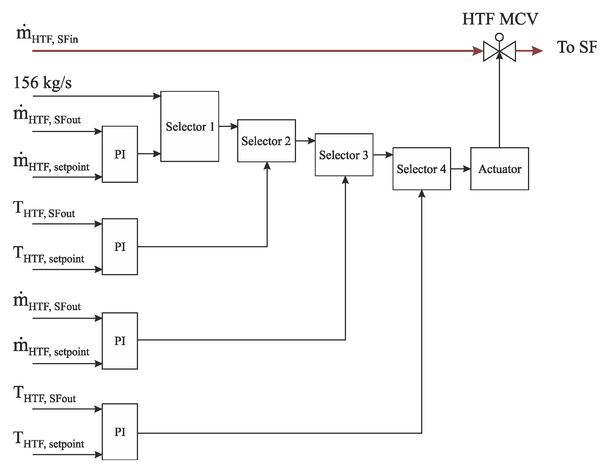
The HTF temperature at the outlet of the SF is regulated using HTF MCV at the inlet of the SF. This control process is performed by regulating the thermal oil mass flow passing through the SF. Two processes are achieved via this control valve: firstly, after sunrise the thermal oil mass flow in the SF is regulated at a constant value of 2.5 kg/s per loop. The thermal oil flow is kept constant at this value until achieving the design temperature of the HTF (295 °C) at the inlet of the SF. Secondly, the thermal oil temperature at the outlet of the SF continues to rise until it reaches its nominal value of (393 °C). Thereafter, this design outlet temperature of the HTF is kept, using this controller (HTF MCV), by increasing or reducing the thermal oil mass flow passing through the solar field. It is worth mentioning that there is a control valve before the inlet of each loop; these valves are controlled by the same procedure that applies to the HTF MCV. The advantage of using these valves is to maintain the design temperature of thermal oil (393 °C) at the loop outlet, when some clouds prevent the solar radiation from falling on a certain loop. Unfortunately, in this study, the location of loops adversely affected by the existing clouds was not available from the supplier. Therefore, the decrease in the heat collected within the solar field was evenly distributed among all loops. It should be mentioned here that each selector includes two functions. These functions are chosen based on one, two, or more boundary conditions for these selectors. The HTF MCV is modelled with four selectors, as demonstrated in
Figure 3 and
Figure 4. The boundary condition of selector 1 is when the DNI has reached a value more than 25 W/m
2, when selector 1 will change its function from a certain orifice (which keeps the thermal oil mass flow at 156 kg/s) to the second function (increase HTF mass flow from 156 kg/s to 390 kg/s). The boundary condition of selector 2 is when the thermal oil temperature reaches the design inlet value of 295 °C. After achieving this condition, selector 2 will choose the second function, which regulates the thermal oil mass flow rate to reach the design temperature of the thermal oil at the outlet of the SF (393 °C). Selector 3 consists of two functions; the first function is applied during normal cases (clear periods), and the second function is activated during the cloudy periods. The second function of selector 3 is enabled when two boundary conditions are achieved: the first condition is that the thermal oil mass flow continues decreasing down to a minimum condition value of 312 kg/s, and the second condition is that the HTF temperature decreases to below 393 °C. After achieving both conditions, the thermal oil mass flow is still unaltered at a minimum value of 312 kg/s, despite the decline in the design outlet temperature of the HTF. Two functions are passed through selector 4, the first of which comes from selector 3. When two boundary conditions are achieved (312 kg/s and 377 °C), the second function starts maintaining the thermal oil temperature of 377 °C at the outlet of the SF by closing the HTF MCV gradually until it is totally closed.
3.1.3. HTF Control Valve at the Outlet of the SF (to Power Block)
The HTF control valve at the outlet of the SF (or to the power block (PB CV
in)) adjusts the thermal oil mass flow that is transmitted to the power block (PB). PB CV
in is opened when the HTF temperature reaches the design temperature value of 295 °C at the inlet of the SF. Then, it continues opening in order to achieve the nominal value of thermal oil mass flow (600 kg/s), with a temperature of 393 °C. This process is achieved by comparing the thermal oil mass flow rate at the SF outlet with a setpoint of 600 kg/s through PI controller, as shown in
Figure 5.
3.1.4. Control Valve of the Thermal Storage System (SF–TS CV)
SF–TS CV is installed between the SF outlet and the TSS inlet; it controls the excess flow of thermal oil into the TSS, as demonstrated in
Figure 6. The operational procedures of this control circuit are implemented based on two cases: In the first case, the valve begins to open when the thermal oil mass flow at the SF outlet exceeds the nominal value of 600 kg/s with a temperature of 393 °C. In the second case, the SF–TS CV starts closing when the solar irradiance is low and the thermal oil mass flow is less than the nominal value (600 kg/s).
3.1.5. HTF Redirection Control Valve (RDCV)
In the evening period, the PB is operated based on the TSS. Therefore, the HTF path should be changed to the TSS instead of the solar field. This process is achieved via HTF redirection control valve (RDCV), as illustrated in
Figure 7. This control circuit includes one selector, and operates with two functions: The first function is that the RDCV remains closed when solar radiation is available. The second function is that the RDCV is gradually opened in order to redirect the HTF to the TSS, and then transfers the thermal power to the power block. Therefore, the selector will change from the first function to the second function after achieving two boundary conditions: the first condition is that the thermal oil mass flow at the outlet of the SF should be less than the design value of 600 kg/s. The second condition is that the level of the hot tank must be more than a minimum value of 0.6 m.
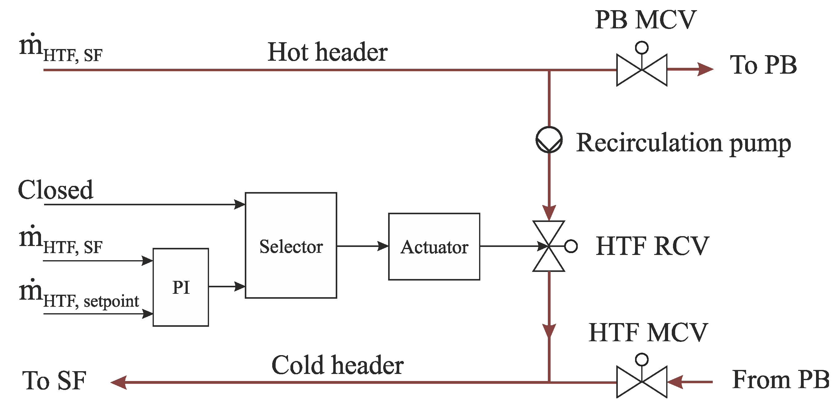
3.1.6. HTF Recirculation Control Valve (RCV)
The HTF recirculation valve (RCV) is installed between the hot header and the cold header in the solar field, as shown in
Figure 8. There are two functions in this control circuit: The first is that the RCV remains closed as long as there is stored energy. The second function is activated when the TSS is completely exhausted. Here, the RCV will be opened to regulate the thermal oil mass flow in the SF at a certain value of 156 kg/s, and continues until the sunrise of the second day.
3.1.7. HTF Protection System
To keep the thermal oil from freezing during the cold periods, a thermal oil protection system is applied in this work. The protection system prevents the thermal oil temperature in the SF from decreasing below a value of 70 °C, and from exceeding the maximum value of 110 °C in the next operation This temperature range is regulated by two protection control valves (PCV
1 and PCV
2), as shown in
Figure 9. Accordingly, PCV
2 starts opening in order to pass HTF through the heaters when the thermal oil temperature at the inlet of the SF decreases below 70 °C. On the other hand, PCV
1 starts closing in order to maintain the thermal oil temperature at the SF inlet in the range of 70–110 °C.
4. Thermal Storage Model
As solar irradiation depends on the daylight and the clarity of the sky, CSP plants are usually non-dispatchable. In order to make them highly dispatchable, a TSS can be added to the CSP plants. Although the solar power source is intermittent, continuous electrical power can be produced due to the use of the TSS. A two-operation mode efficiencies (during charge and discharge modes) of more than 96 % was documented for TSS units consisting of hot and cold storage tanks of the molten salt [
38].
The storage system studied in this work will be explained based on two operation modes, including all control circuits.
The excess solar irradiation is transferred to the TSS and provided as a substitute for the energy lost because of the clouds or during the night. This system allows for high operating flexibility, and produces more stable electricity. Hot and cold insulated tanks are connected by heat exchangers in APROS. The molten salt in both tanks is transferred to the heat exchangers by the series of thermal storage pumps that are located after the thermal storage tanks. The molten salt can be defined as a solution of potassium and sodium nitrates with known specifications.
In the charge mode, the thermal oil from the SF heats the molten salt that flows from the cold tank to the hot storage tank, with a temperature of approximately 386 °C. It should be mentioned here that there will be losses in the heat exchangers between the thermal oil and the molten salt. This means that the hot molten salt will reach a temperature below the maximum value of HTF temperature of 393 °C, whereas the hot molten salt will reach a temperature of 386 °C. Note that the capacity of this system can reach a maximum value of about 1025 MWth h.
The thermal energy in the thermal storage system can be used in the discharge mode, where the hot molten salt heats the thermal oil through the heat exchangers. Here, the thermal storage system provides the nominal mass flow of the HTF (600 kg/s) with a temperature of 377 °C in the evening period. This will affect the steam production performance, whereas the nominal amount of generated steam (55 kg/s) in the daylight will not be accomplished during the evening period. However, the hot thermal oil is transmitted to the PB. After that, the thermal oil is returned to a cold tank with a temperature of about 292 °C.
4.1. Thermal Storage Control Structures
In order to regulate the thermal storage process during the dynamic simulation, it is necessary to implement control circuits that maintain the nominal temperature and mass flow rate conditions for the molten salt and the HTF. Hence, three control circuits are modelled in the thermal storage system, in order to obtain reasonable responses during the continuous changes in operating conditions.
4.1.1. Control Valve at the Thermal Storage System Inlet (TS MCVi)
The control valve at the thermal storage system inlet includes two tasks, depending on the operation mode of the thermal storage system, as shown in
Figure 10. The first task is applied during charge mode, where this valve allows the surplus of thermal oil with a temperature of 393 °C to pass through it into the heat exchangers in order to transmit the thermal power from the HTF to the molten salt. Thereafter, the HTF leaves the TSS with a temperature of 293 °C through the control valve at the thermal storage system outlet (TS MCV
o). Subsequently, the HTF that exited the thermal storage system will be mixed with the HTF, which comes from the PB and enters the SF again. The second task is activated during the cloudy periods and the evening hours; in the compensation periods, the direction of the HTF flow will be reversed, where the HTF flows directly from the PB to the TSS through the redirection control valve (RDCV), and then through TS MCV
o. Therefore, TS MCV
o and TS MCV
i are considered to be the inlet and outlet of the TSS, respectively. Afterwards, the heated HTF flows to the PB to replenish the rest of the nominal mass flow (600 kg/s).
The HTF flow direction is reversed based on two conditions (THTF = 393 °C, and = 600 kg/s) that are applied to the selector: Firstly, this control valve remains open when the HTF flow is directed from the SF to the TSS (SF–TS direction) during charge mode, as long as the design temperature of the thermal oil at the outlet of the SF and the nominal HTF mass flow are achieved. Secondly, when the one of the mentioned conditions (393 °C and 600 kg/s) is not accomplished, the discharge mode starts, and the HTF flow direction is changed from the SF–TS to the TS–PB direction.
4.1.2. Control Valve at the Thermal Storage System Outlet (TS MCVo)
The control valve at the outlet of the TSS controls the process of thermal energy compensation. This controller has two functions, as illustrated in
Figure 11. The first function is that TS MCV
o remains open, like the TS MCV
i, during charge mode, where TS MCV
i and TS MCV
o are considered to be the inlet and outlet of the TSS, respectively. During discharge mode, the second task is enabled, and the thermal oil flow is directed from TS MCV
o to TS MCV
i. TS MCV
o regulates the mass flow of the thermal oil in order to maintain the nominal value of 600 kg/s at the PB inlet during the evenings and cloudy periods.
4.1.3. Hot Tank Control Valve (HTCV)
The hot tank control valve is located after the pumps of the hot tank in the thermal storage system. This control circuit includes two functions, as shown in
Figure 12. The first function is that this valve remains closed during charge mode (the molten salt is transferred from the cold drum to the hot drum through the heat exchanger). The second task is enabled when the thermal oil temperature at the outlet of the solar field decreases below the design outlet temperature (393 °C or 377 °C, during the daylight or in the evening period, respectively). It should be mentioned here that the setpoint of the HTF temperature will be changed automatically from 393 °C to 377 °C based on the temperature value, which is regulated by the HTF MCV. However, the hot molten salt is sent to the heat exchangers through the HTCV, which in turn regulates the design HTF temperature at the inlet of the PB during the cloudy and night periods. Thereafter, the energy stored in the hot salt drum is transmitted into the HTF which, in turn, transfers this energy into the power block to produce the steam.
5. Conclusions
A large number of works can be found regarding parabolic trough power plants; however, few studies focus on the dynamic behaviour of the secondary systems—e.g., the TSS, taking into account stable electrical power and capacitance factor enhancement. A particular focus is placed on the modelling of the SF. Most works refer to the use of a simplified steady-state model instead of a comprehensive dynamic model of these power plants. In order to understand the dynamic behaviour of the secondary systems (SF, TSS, and PB) with high accuracy, more consideration should be devoted to the thorough modelling of the power plants.
In this study, detailed solar field and thermal storage system models for a parabolic trough power plant are implemented based on the specifications from data obtained from Andasol II, located in Spain. In this work, the components of these models have been accurately modelled using APROS software.
A detailed SF model was modelled with 156 collector loops, as well as implementing many control circuits to regulate the operation processes. Therminol VP-1 was used as an HTF in the SF. The reference solar field was designed to operate with maximum HTF mass flow (1170 kg/s) at the design outlet temperature (393 °C). Hereby, the solar field operates with a total capacity of useful thermal energy of approximately 280 MWth.
A comprehensive TSS was implemented using hot and cold insulated drums and, between them, heat exchangers. Moreover, the control circuits of this system are described. The thermal storage system was operated with two operation modes—namely, charge mode and discharge mode. During charge mode, the HTF from the solar field at a temperature of 393 °C heats the molten salt (sodium and potassium nitrates) that is pumped from the cold tank to the hot tank and stored with temperature of approximately 386 °C. This process continues until achieving a maximum capacity of stored energy of about 1025 MWth h. This thermal storage provides high operational flexibility and stable electricity generation.
On the other mode, the hot salt heats the thermal oil via the heat exchangers. The molten salt exits the heat exchangers and is sent into the cold tank at a temperature of about 292 °C. Accordingly, the thermal storage system will provide the thermal power at the nominal load (125.75 MWth) for a period of approximately 7.5 h in the evening period.
The purpose of this work was to provide reference models for the SF and TSS. This, in turn, will help researchers and designers to understand the advanced control circuits of these stations. In addition, these models can determine the best manner of power plant operation.
Future studies will be focused on a detailed description of the power block controllers.


