Article

Co-Package Technology Platform for Low-Power and Low-Cost Data Centers

by
Konstantinos Papatryfonos
1,*,
David R. Selviah
1,*,
Avi Maman
2,
Kobi Hasharoni
2,
Antoine Brimont
3,
Andrea Zanzi
3,
Jochen Kraft
4,
Victor Sidorov
4,
Marc Seifried
5,
Yannick Baumgartner
5,
Folkert Horst
5,
Bert Jan Offrein
5,
Katarzyna Lawniczuk
6,
Ronald G. Broeke
6,
Nikos Terzenidis
7,
George Mourgias-Alexandris
7,
Mingchu Tang
1,
Alwyn J. Seeds
1,
Huiyun Liu
1,
Pablo Sanchis
3,
Miltiadis Moralis-Pegios
7,
Thanasis Manolis
7,
Nikos Pleros
7,
Konstantinos Vyrsokinos
8,
Bogdan Sirbu
9,
Yann Eichhammer
9,
Hermann Oppermann
9 and
Tolga Tekin
9
add Show full author list remove Hide full author list
1
Department of Electronic and Electrical Engineering, University College London, UCL, London WC1E 7JE, UK
2
DustPhotonics, 11 Tzela Hahar St., Modiin 7178457, Israel
3
Valencia Nanophotonics Technology Center, Universitat Politècnica de València, 46022 València, Spain
4
ams AG, Tobelbader Strasse 30, 8141 Premstaetten, Austria
5
IBM Research–Zurich Laboratory, Department of Science and Technology, 8803 Rueschlikon, Switzerland
6
BRIGHT Photonics B.V., Horsten 1, 5612 AX Eindhoven, The Netherlands
7
Department of Informatics & Center for Interdisciplinary Research & Innovation, Aristotle University of Thessaloniki, 57001 Thessaloniki, Greece
8
Department of Physics, Aristotle University of Thessaloniki, 57001 Thessaloniki, Greece
9
Fraunhofer Institute for Reliability and Microintegration (IZM), Gustav-Meyer-Allee 25, D-13355 Berlin, Germany
*
Authors to whom correspondence should be addressed.
Appl. Sci. 2021, 11(13), 6098; https://doi.org/10.3390/app11136098
Submission received: 1 June 2021 / Revised: 25 June 2021 / Accepted: 28 June 2021 / Published: 30 June 2021
(This article belongs to the Special Issue Frontiers in Optical Interconnects)

Abstract

:
We report recent advances in photonic–electronic integration developed in the European research project L3MATRIX. The aim of the project was to demonstrate the basic building blocks of a co-packaged optical system. Two-dimensional silicon photonics arrays with 64 modulators were fabricated. Novel modulation schemes based on slow light modulation were developed to assist in achieving an efficient performance of the module. Integration of DFB laser sources within each cell in the matrix was demonstrated as well using wafer bonding between the InP and SOI wafers. Improved semiconductor quantum dot MBE growth, characterization and gain stack designs were developed. Packaging of these 2D photonic arrays in a chiplet configuration was demonstrated using a vertical integration approach in which the optical interconnect matrix was flip-chip assembled on top of a CMOS mimic chip with 2D vertical fiber coupling. The optical chiplet was further assembled on a substrate to facilitate integration with the multi-chip module of the co-packaged system with a switch surrounded by several such optical chiplets. We summarize the features of the L3MATRIX co-package technology platform and its holistic toolbox of technologies to address the next generation of computing challenges.

1. Introduction

The continuous growth of hyperscale data centers (DCs) designed to handle cloud applications, social media and big data analytics is driving the datacom industry-servers, switches and optical interconnects. Hyperscale DCs are organized in several hierarchy layers and include hundreds of thousands of servers. Thus, they require an efficient interconnection network that is both low-cost and energy-efficient [1,2]. The DC interconnection network is based on high capacity, high throughput Ethernet switches that handle packet parsing, buffering and queuing. These switch ASICs are characterized by their digital processing power (number of packets processed per second) and the bandwidth of the analog interfaces to the chip (number of I/O ports). With every generation of switch silicon, the I/O bandwidth doubles, thus, enabling faster logic processing capabilities. The current generation of Ethernet switch systems use a 12.8 Tb/s [3] switch bandwidth.
The architecture of modern DCs is based on non-blocking Clos topology [4], in which all compute and storage nodes are connected to each other in a full mesh configuration. A prerequisite for such a network is that the switches connecting all the nodes have a large enough chip radix to avoid traffic congestion. However, the number of I/O ports is limited due to packaging constraints, thus forcing an increase in both the optical and electrical line rate with each switch generation.
Increasing the electrical lane speed from 50 Gb/s (25 GBd PAM4) to 100 Gb/s (50 GBd PAM4) requires advanced equalization for the serializer-deserializer (SerDes) at each I/O port. A DSP is thus realized at each port to enable the electrical link from the switch across the linecard to the optical transceiver on the front panel of the switch (Figure 1a). Using the advanced 7-nm CMOS node, the power consumption of a single port is in the 700 mW range. Given that a 51 Tb/s switch has 512 ports, the chip I/O consumes about 350 W out of a total chip power of ~900 W. This means that less power is available for packet processing, leading to inefficient use of the overall bandwidth. Adding to this figure is the power of the 64 optical transceivers, each at 800 Gb/s (~20 W)-so the switch chip I/O consumes more than 1500 W.
A second limitation on such high bandwidth devices is related to signal integrity. Routing the high-speed traffic through the switch ASIC package introduces losses due to reflection and impedance mismatch of the signal crossing the package core. These problems are so serious that switch vendors are now considering alternative technologies to enable the next generation of devices [5]. Reducing the SerDes power consumption and improving signal integrity can be carried out only if the long metal traces on the board (Figure 1a) are eliminated. In that case, the SerDes is required to handle a trace loss of 1–2 dB, compared with the >20 dB trace loss of the standard design. This can be carried out if the optical interconnect is co-packaged with the switch ASIC (Figure 1c). Hybrid integration (Figure 1d) with the III–V optoelectronics assembled directly onto the ASIC was demonstrated to be a very promising approach, notably enabling o triple the number of chip I/O ports [6]. However, several challenges need to be overcome before it can be fully implemented, mainly related to its high complexity and thus relatively high cost. This approach requires a customized fab as each time we change the laser, we must adapt the PIC and vice versa. Therefore, co-packaging is very suitable as an intermediate step before full integration (Figure 1e) may be achieved. More details regarding the extensive work that has recently been carried out on researching the co-integrated optical I/O may be found in the literature [2,7,8,9,10].
In this paper, we report recent advances achieved by the EU H2020-funded consortium entitled Large Scale Silicon Photonics Matrix for Low-Power and Low-Cost Data Centers (L3MATRIX) [11], which was comprised of leading companies and universities in the field of SiP. L3MATRIX focused on the development of a 2-dimensional 4 × 16, 1.6 Tb/s (64 × 25 Gb/s) silicon photonic high-radix transmitter matrix and co-packaging with a switch ASIC to mitigate the on-board bandwidth/distance product limitations of traditional SerDes. The footprint of each individual cell size encompassing the modulators, lasers, rib/strip transitions and grating couplers is 1000 μm × 1750 μm. By using a 1-cm2 1.6 Tb/s silicon PIC interposer flip-chipped onto the ASIC chiplet (1.6 Tb/s/cm2), L3MATRIX aims to propose a potential compact solution to feed 25.6 Tb/s Switching ASIC. The discussed technology has been developed, having in mind two strict requirements. First, in such a tight space, it is critical that each individual component releases as little heat as possible; therefore, low-voltage and low-current operation has been set as a high priority, together with low-cost solutions in order to accommodate future DC priorities. Most importantly, all the parts of this technology, as will be discussed through this paper, are being developed without recurring to CMOS-incompatible materials and utilizing only processes that are compatible with the AMS AG foundry standards in order to allow for low-cost mass-production when the technology reaches the required maturity.
The paper is structured as follows: In Section 2, we propose a new system architecture and analyze it. We also introduce the mask design and layout tools that we employed in the following sections. Section 3 reports our advances in SiP fabrication for this application and relates them to key performance improvements. Section 4 discusses our achievements with respect to integrated laser sources, in which we have worked with both quantum well (QWell) and quantum dot (QD) based active media. Improved modulators of both conventional and slow-light design are analyzed in Section 5, while the 3D system integration, chiplet assembly and matrix vertical fiber coupling are discussed in Section 6. Section 7 discusses the future perspective and open questions arising from our main results, and Section 8 concludes the paper. We emphasize that all steps that will be presented have been designed for high-volume manufacturing and tested for compatibility with existing industrial production lines. This is particularly important for the problems that are addressed, as very often, lab demonstrations may exhibit impressive individual performances, but it is impossible to scale them up for production.

2. System Architecture and Design

2.1. System Architecture

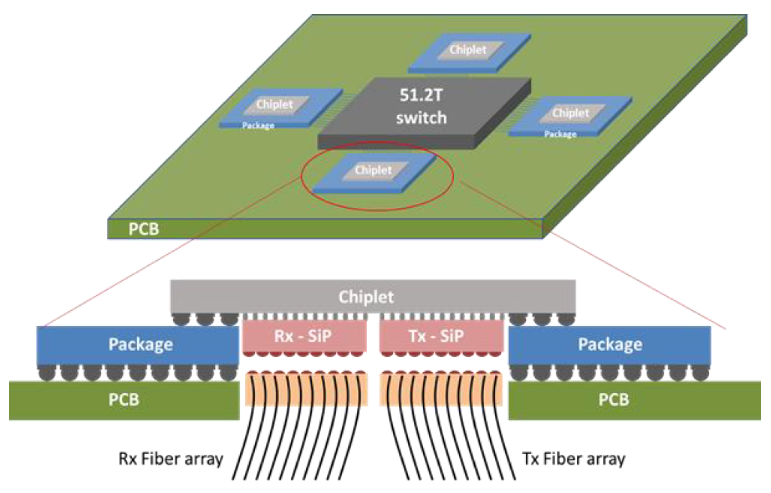
Reducing the SerDes power consumption can be carried out only if the chip I/O is physically decoupled from the switch ASIC. In that case, a custom chiplet is assembled next to the switch that handles all I/O tasks (Figure 2). The 64 pluggable transceivers are re-arranged into large silicon photonics (SiP) matrices assembled directly on the chiplet. Fiber ribbons are used to route the traffic to the front panel of the switch chassis.
This approach is in-line with the industry’s long-term goal of integrating photonics and digital electronics, shown in Figure 1. Starting with pluggable transceivers, the optical interconnect is moved closer to the ASIC with each generation until full integration (Figure 1d,e) will be obtained. On-board (Figure 1b) optics technologies have been widely investigated with several reported demonstrations, including from Intel, Luxtera, Elenion and others (see [12,13,14,15] and references therein). Co-packaging (Figure 1c) is thus the next step after on-board optical engines.
Decoupling chip I/O from the switch ASIC implies that the chiplet handles all tasks associated with I/O. Typically, the Medium Access Control (MAC)and Forward error correction (FEC) blocks are moved from the switch to the chiplet. Additional macros can be relocated as well, such as redundancy management, load balancing, etc. The interface between the two chips can be either a parallel bus or a low-power SerDes. In the latter case, an equalizer is not required as the switch and chiplet are only a few mm apart. The power consumption thus drops from 700 mW per 100 Gb/s to less than 200 mW. The SerDes array on the switch ASIC is distributed on the chip perimeter; therefore, 4 or 8 chiplets are used, each handling 6.4 or 12.8 Tb/s and assembled around the switch ASIC.
The front panel pluggable transceivers are rearranged into large, 2D SiP matrices that are assembled directly on each chiplet. Using 25 Gb/s per lane, each transmitter cell in a 64 element SiP matrix contains a 25 G modulator and a laser source. The modulated signals from 4 adjacent cells are Coarse Wavelength Division Multiplexed (CWDM) and fiber coupled. The laser source can be integrated within the SiP cell or may be fiber-coupled from an external laser bank. In the former case, the laser may suffer from thermal instability due to the proximity to the very hot switch, while in the external source case, a higher loss is anticipated due to the two additional coupling steps. A receiver SiP matrix is assembled next to the transmitter SiP matrix with integrated photodiodes and wavelength de-multiplexing for every 4 cells.
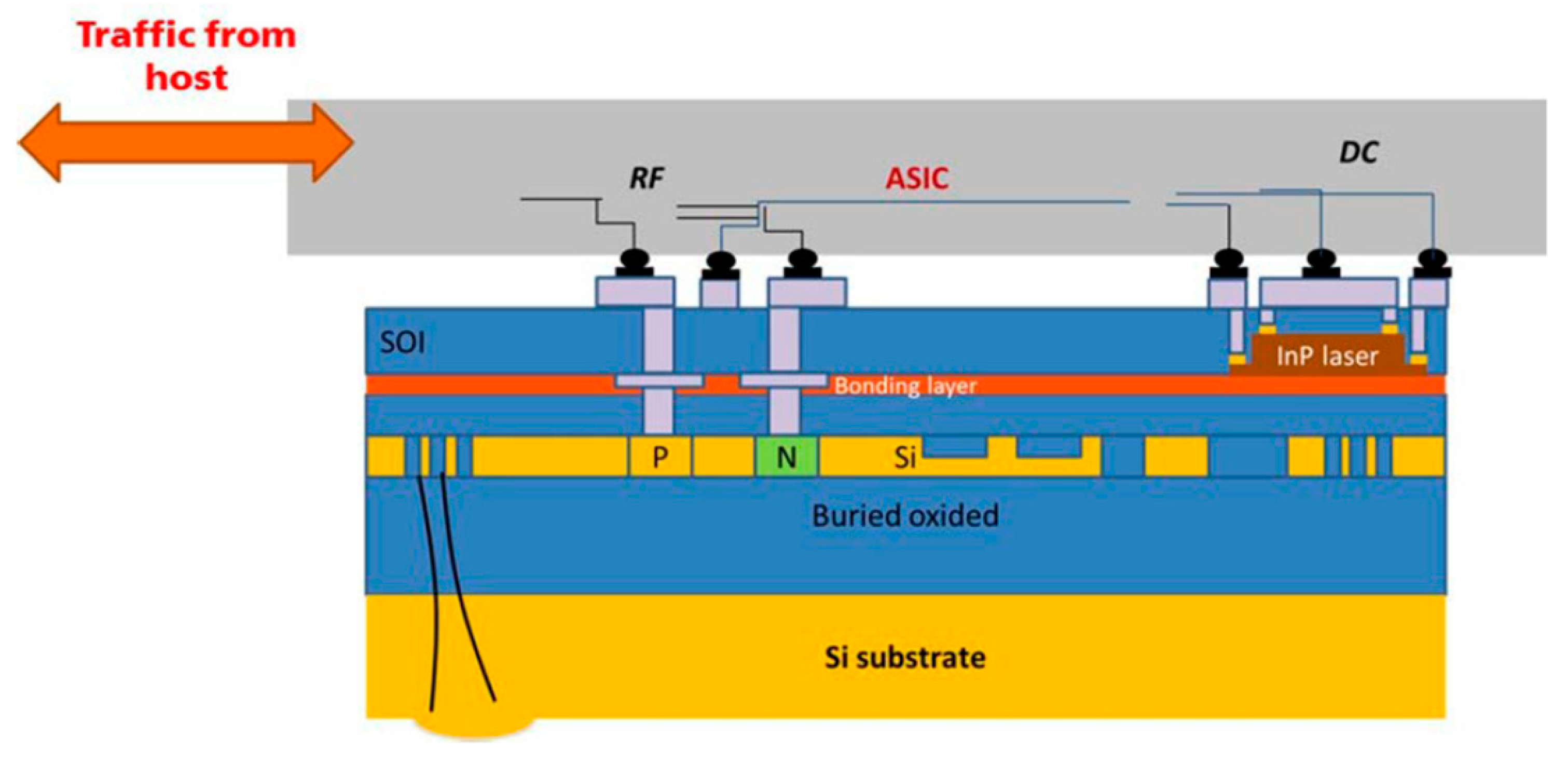
Driving the transmit and receive SiP matrix arrays is carried out using analog drivers and trans-impedance amplifiers within the chiplet. Thus, a modulator driver is located directly below each modulator (Tx), and a trans-impedance amplifier is located directly below each photodiode (Rx). The short (~50 µm) distance between the analog driver and the optoelectronic component ensures that parasitics are kept to a minimum on the transmission line. A cross-section of this design is shown in Figure 2. As shown in Figure 2, the lasers and modulators are on the lower part of the SiP chip. Since the 2D SOI chip is assembled such that its front side faces the ASIC, the device is back-illuminating with light propagating from the grating coupler (GC) through the Silicon substrate (Figure 2 and Figure 3) to a set of microlenses that couple it to the single-mode fiber. The microlens array is flipchip assembled onto the back surface of the SOI chip. Alignment marks are fabricated on this surface using a dual-side mask aligner. Figure 3 shows a detailed cross-sectional view of the L3MATRIX integration scheme.
The number of optical lanes desired should be as high as possible to reduce the cost per Gb/s. Our 2D optical interconnect is designed such that each 4 cells are on a CWDM grid and multiplexed into one of the 16 single-mode fibers, each of which carries a bit rate at a single wavelength of 25 Gb/s; thus, the matrix operates at 1.6 Tb/s (16 × 4 × 25). The SiP matrix is made up of identical unit cells where each cell is self-contained with its own modulator, laser source and GCs, and each cell in the matrix is optically and electrically isolated from its neighbors.

2.2. Mask Layout Integration and Design Methodology

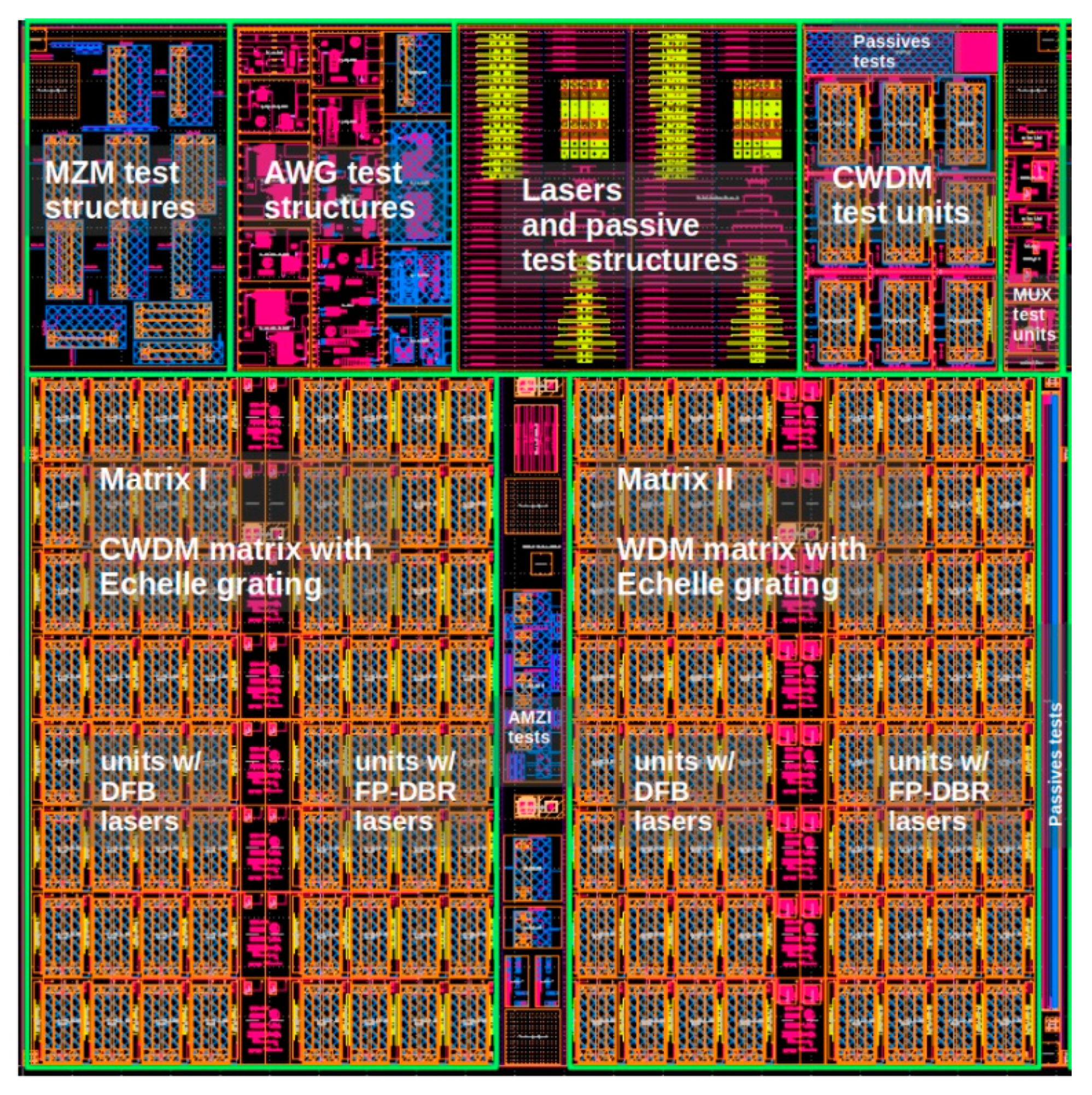
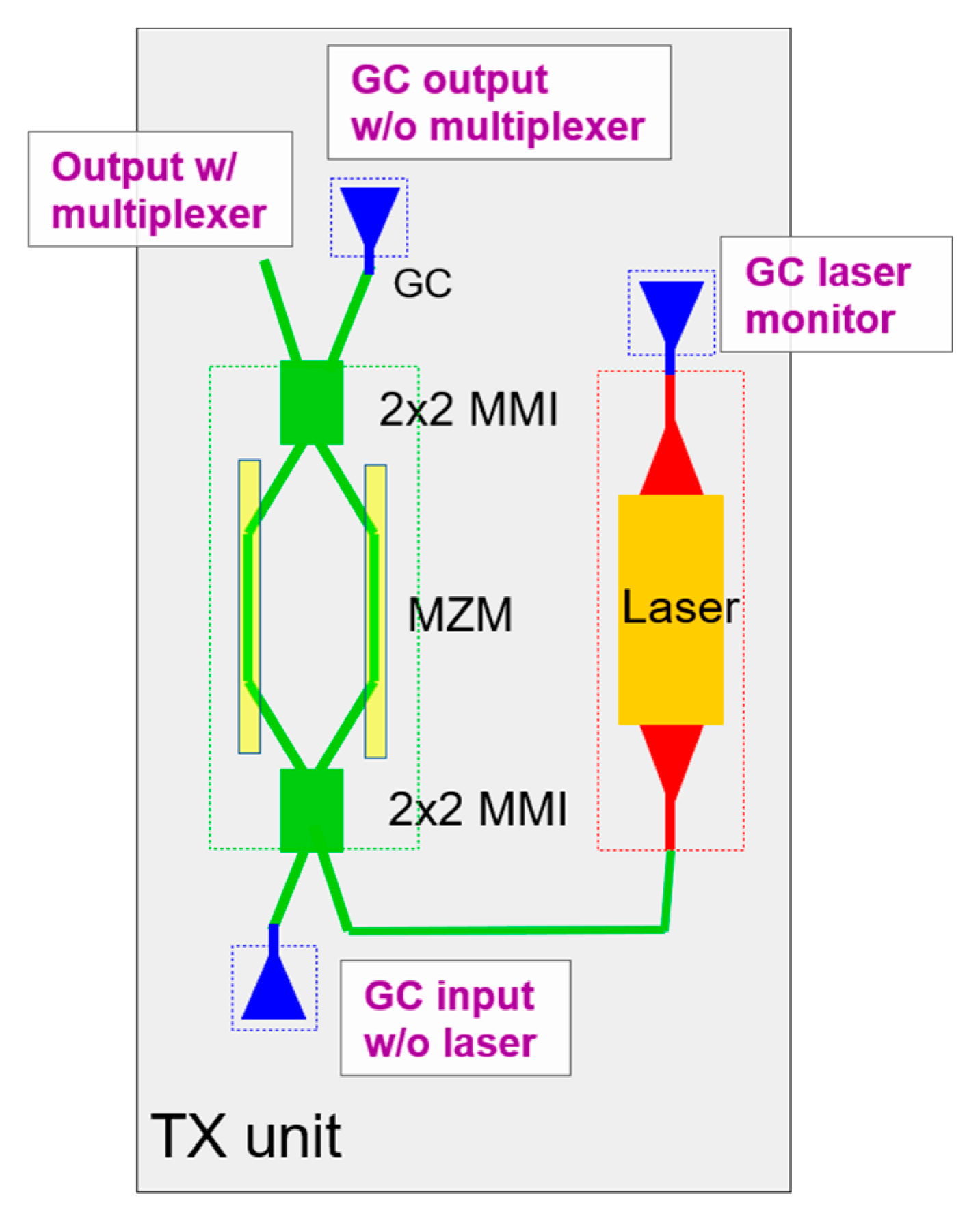
The design of complex integrated circuits, such as our SiP matrix, requires an efficient design flow and accurate design tooling to facilitate interactions between multiple designers and compatibility between multiple technologies [16]. An open-source photonic IC design framework-Nazca-Design [17] was used as the layout design environment. The tool enabled a hierarchical methodology in which different designers contributed components, sub-circuits and test structures to a single project. Nazca-Design provided a direct interface between the designer and the foundry through process design kits (PDKs), accessed via name-spaces so that a mix of technology and packaging information could be exchanged during the mask layout integration. The tool facilitated the exchange of components in Python-script and in a mask layout (e.g., GDSII) format. The Nazca-Design framework is open source but does protect proprietary information inside the PDKs and designers’ IP. A foundry, or others, can securely distribute black box design information (e.g., with modulator or laser designs) to be replaced at the foundry side upon manufacturing. Beyond the state-of-the-art in PIC design, the tool includes a methodology for dealing with PDK versioning and a focus on a robust exact copy philosophy for high-fidelity volume production design work. Figure 4 shows our final reticle design that we manufactured at the AMS foundry. It includes our 64 element SiP matrix circuits and various test structures provided by the designers in this project. Figure 5 depicts our unit cell layout for WDM and CWDM. The IEEE 802.3 LN WDM grid was finally selected, in which the 4 channel wavelengths correspond to 1295.56 nm, 1300.05 nm, 1304.58 nm and 1309.14 nm, because the reduced 20-nm bandwidth imposes a more realistic specification on the gain bandwidth, compared to a 20 nm channel spacing (80-nm bandwidth).

3. Silicon Photonics

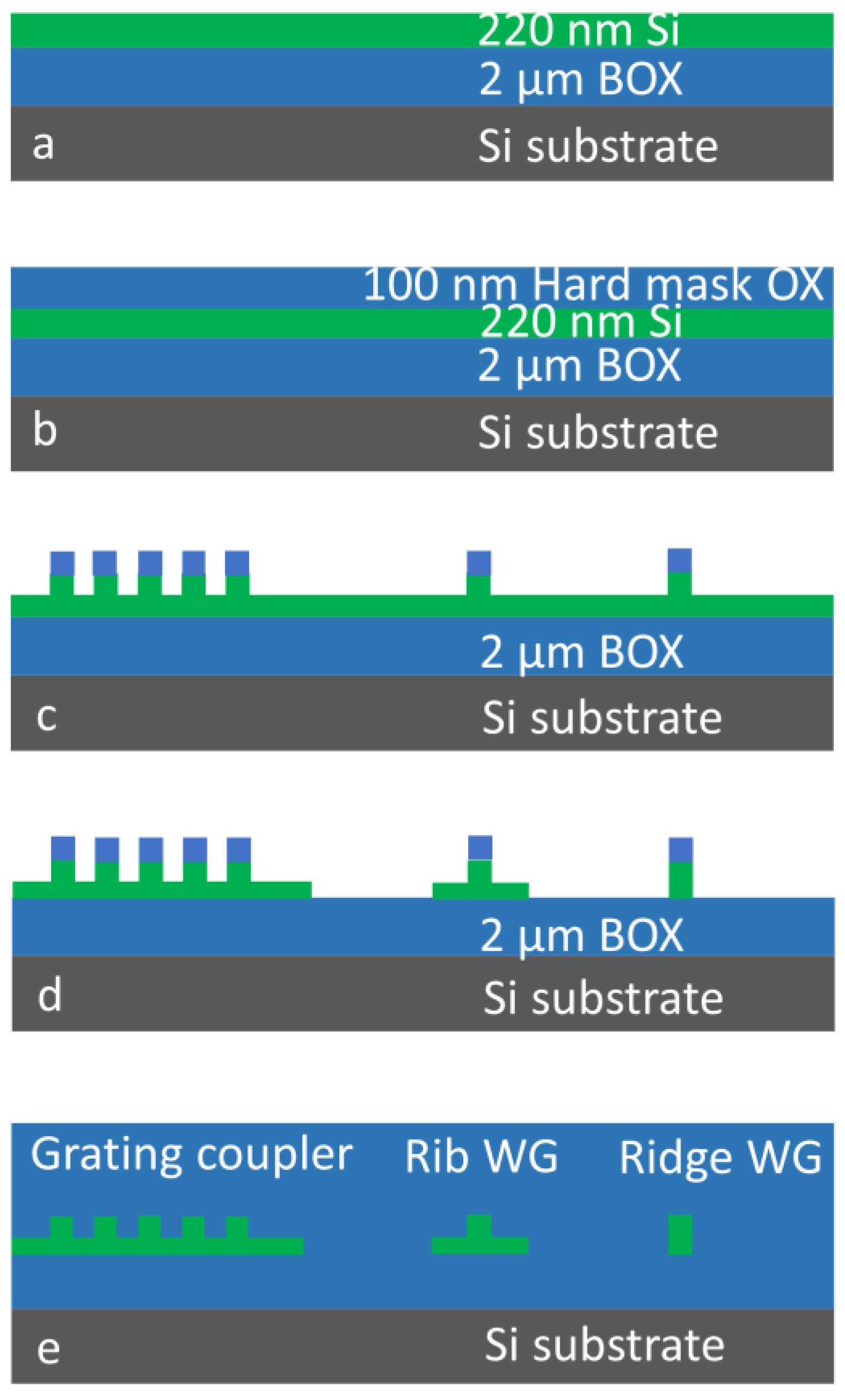
We fabricated our SiP circuit on silicon-on-insulator (SOI) wafers in the AMS foundry. The top silicon layer of the SOI wafer was structured and modified by microelectronics manufacturing processing to create both passive and active photonic elements. The underlying bonding silicon dioxide layer (BOX) served as the bottom cladding of these light-guiding elements. The main steps of the passive device fabrication process are shown in Figure 6, which also describes the process used for the modulators. The fabrication process started with a thin layer of silicon dioxide deposited on the top silicon surface of the SOI wafer. Lithography and selective etching were then used to structure this layer, creating the hard mask that served for the subsequent partial silicon etching. This shallow silicon etching created rib devices (waveguides and grating couplers), as shown in Figure 6c. The next lithography step served to protect the shallow-etched areas and the subsequent selective silicon etching to remove all non-protected silicon. This selective etching step stopped on the underlaying bonding silicon dioxide, as shown in Figure 6d. A final silicon dioxide deposition step was used for upper cladding and planarization (Figure 6e), embedding the silicon structures. This relatively short process is part of the full PIC manufacturing process, and it is used for time-saving experiments on passive devices as well.

3.1. Waveguides

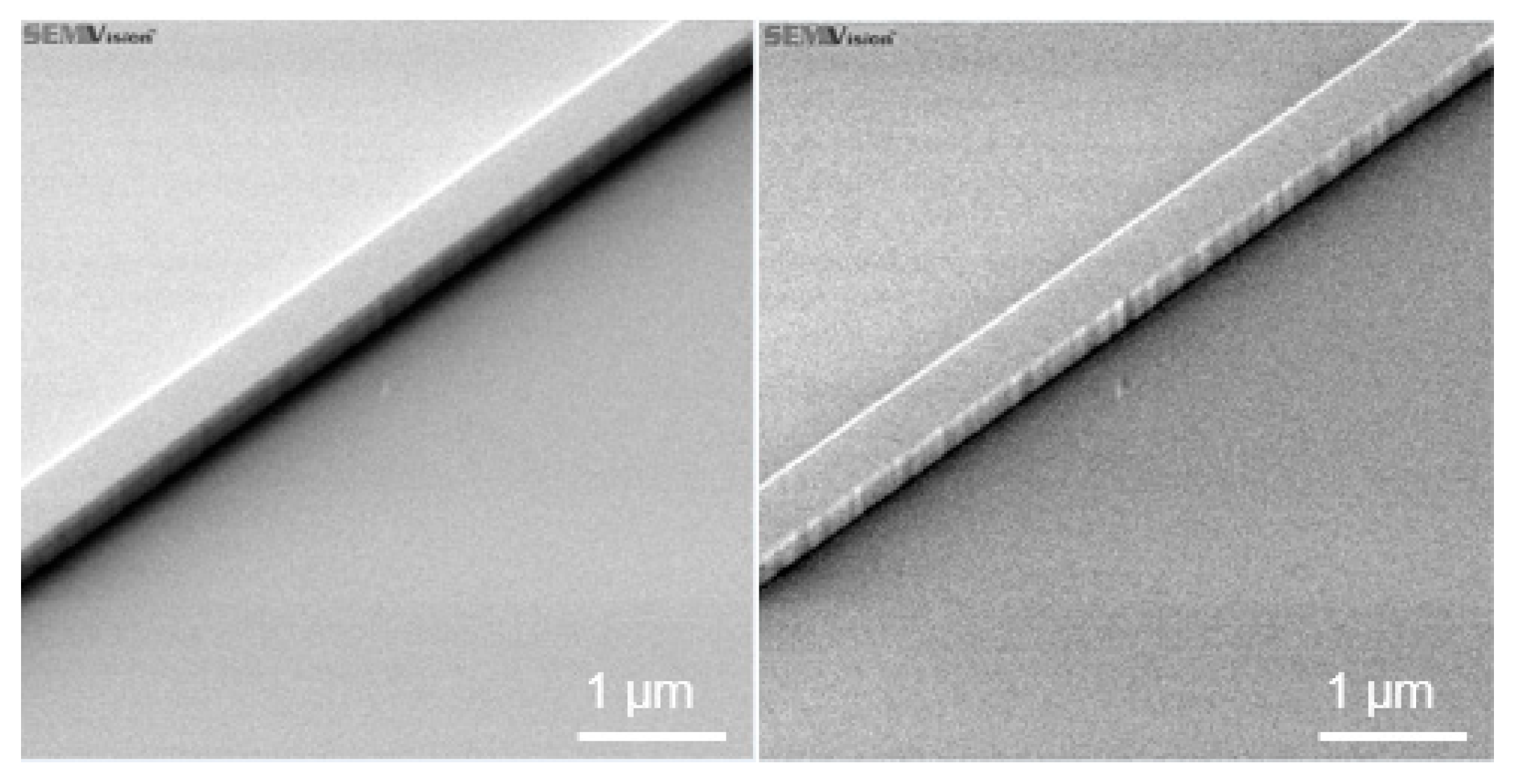
Waveguides are a core element of integrated photonic circuits. Their most important characteristic is their propagation loss, for which the dominant cause is the sidewall roughness [18]. This parameter is difficult to estimate and requires special conditions to observe. Figure 7 shows an SEM micrograph of the same view field inspected by different SEM detectors. Adjustment of the microscopy conditions enables correct detection and characterization of the sidewall roughness.
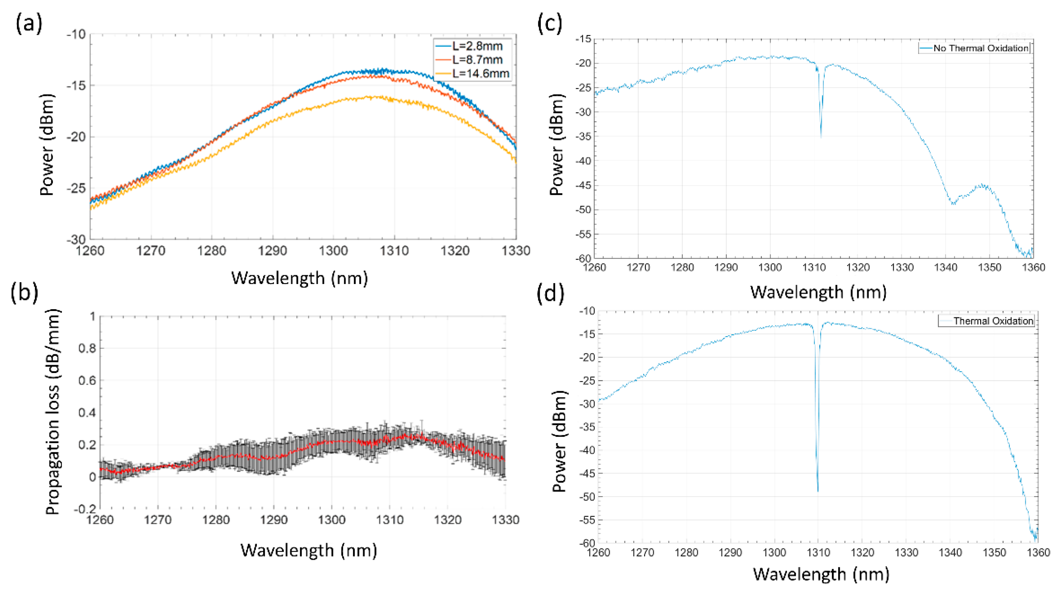
The sidewall roughness development starts from the lithography process and is transferred into the silicon by dry etching. Different types of the process could be used to reduce silicon waveguide sidewall roughness, such as photoresist reflow [19], more isotropic silicon etching [20], or sidewall roughness smoothing postprocessing [21]. In our manufacturing process, we used the latter-smoothing of completely etched waveguides by oven wet oxidation at 1050 °C to create 26 nm of thermal silicon dioxide. This process consumes 12 nm of silicon and sufficiently planarizes the sidewalls following its diffusion mode. The transmission loss measured on these passive devices is reduced from 7 dB/cm down to 1.5 dB/cm after applying this process (Figure 8a,b). In addition, the spectral noise clearly improved in all spectra. Moreover, as seen in Figure 8d,c, the slow-light waveguides (discussed in detail in Section 5) feature a much deeper band gap after thermal oxidation, which is a clear indication of the sidewall roughness reduction.

3.2. Gratings

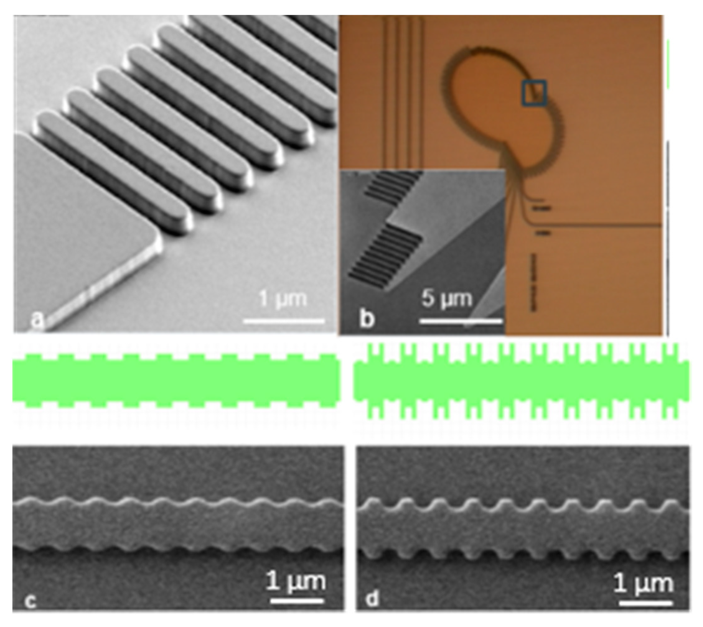
We used two types of grating structures in our design. The first are vertical modulated distributed Bragg reflector (DBR) gratings integrated into waveguides and into Echelle gratings (Figure 9a,b, respectively). The second are laterally modulated distributed feedback (DFB) slow-light grating structures, depicted in Figure 9c,d.
As can be seen in Figure 9c, the pattern transfer of the laterally modulated structures was distorted from the original layout, which was caused by lithography limitations. To account for this, we modified the layout using optical proximity correction (OPC), as shown in Figure 9d top (green pattern). The resulting lateral grating demonstrates sufficiently sharpened corners as well as an increased lateral degree of modulation.

3.3. Directional Couplers

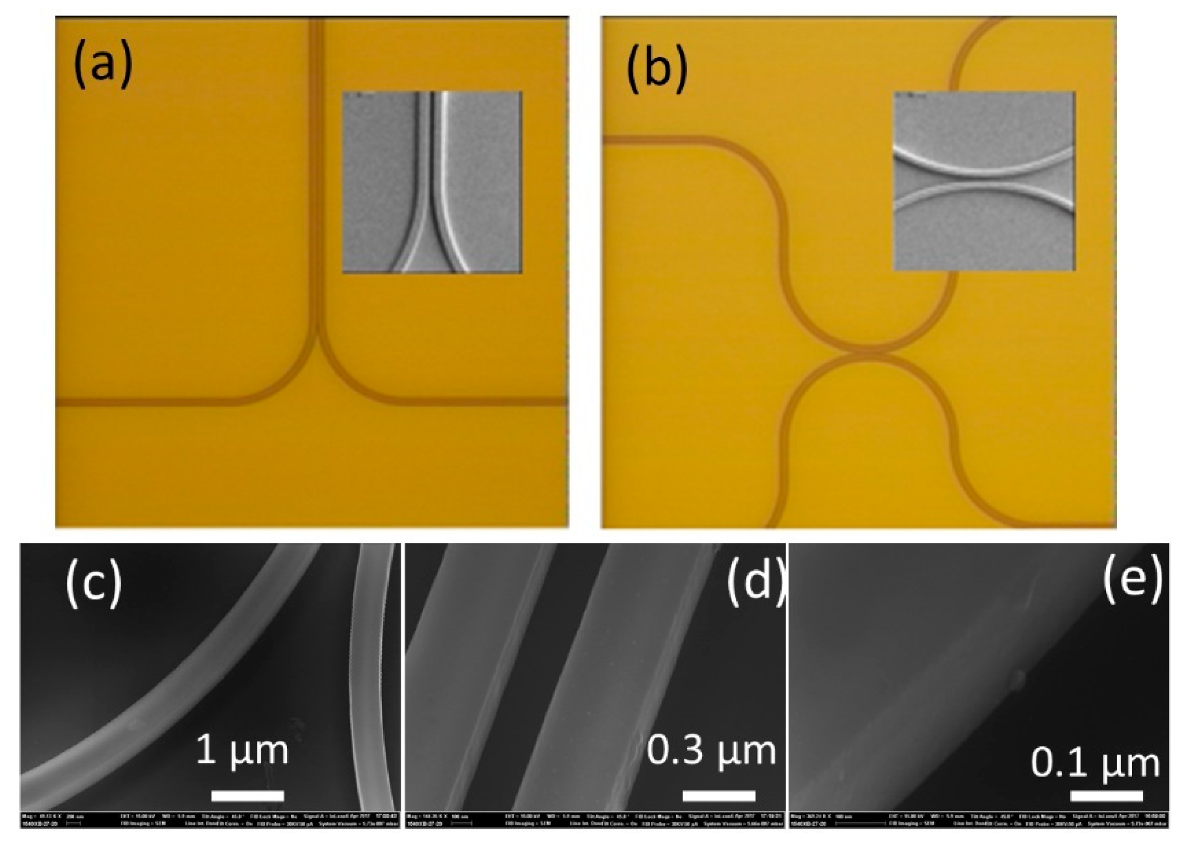
To fabricate the directional couplers, the same process as described in Section 3.1 was employed. Typical optical and SEM micrographs of the achieved couplers are depicted in Figure 10a,b. SEM analysis demonstrates that with the new optimized fabrication process, the sidewall roughness has been substantially reduced, even in the directional couplers bends, as shown in Figure 10c,e.

3.4. Grating Coupler

Our grating couplers were created by a two-step silicon etching process. The process steps are depicted in Figure 11: the first lithographic step defines the grating as well as the rib waveguides on the surface of the silicon dioxide hard mask. The etching includes a sequence of organic bottom antireflection coating (BARC), SiO2 hard mask and time-controlled 70-nm of Si etching (Figure 11a). Then the lithography for a second (complete) silicon etching is applied, and the photoresist protects the grating coupler area (Figure 11b) as well as the rib waveguides (not shown in these micrographs). The resulting two-step silicon structure on the bonding SiO2 surface can be seen in the inset of Figure 11c.

3.5. System Testing

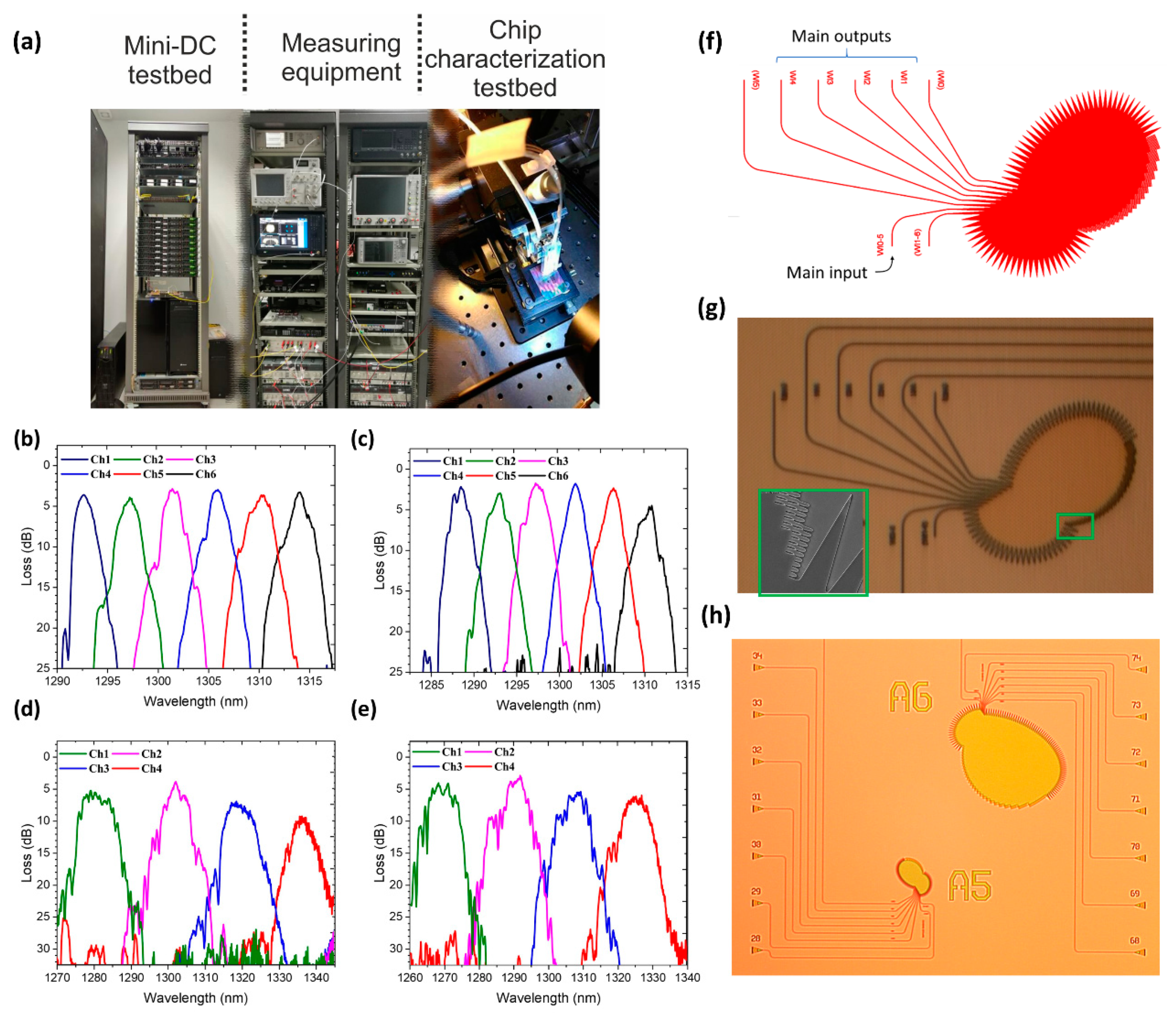
In order to assess the L3MATRIX system’s capabilities in more detail, we developed a specialized testbed to allow for characterization from a single component up to a system-level demonstration under realistic conditions. The testbed, depicted in Figure 12a, comprised FPGA boards with multiple high-speed RF and optical interfaces (SFP28/QSFP28) and servers with different network interfaces spanning from 10 Gb/s SFP+ up to 100 Gb/s QSFP28. In addition, commercial L2/L3 switches employing front-panel pluggable modules, along with miscellaneous testing equipment to interface with the L3MATRIX technology. Figure 12b–e depicts indicative experimental results from L3MATRIX final demonstrator devices. As already described, the development of our interconnection scheme requires all-optical multiplexers and demultiplexers, such as Echelle gratings [22]. To this end, 2 × 6 and 2 × 4 Echelle grating structures have been included in the fabricated chip of Figure 4, and both have been measured in our testing and characterization testbed, revealing the corresponding channel response of Figure 12b–e, respectively. The channels of the two Echelle gratings are following a Gaussian response, with the channel spacing being 4 nm and 20 nm for the 2 × 6 and 2 × 4 configurations, respectively. Further details for our Echelle structures are shown in Figure 12f–h, including the layout and two optical micrographs. The inset of Figure 12g shows an SEM image of the region of the Echelle grating that is indicated by the respective green rectangle.

4. Light Sources

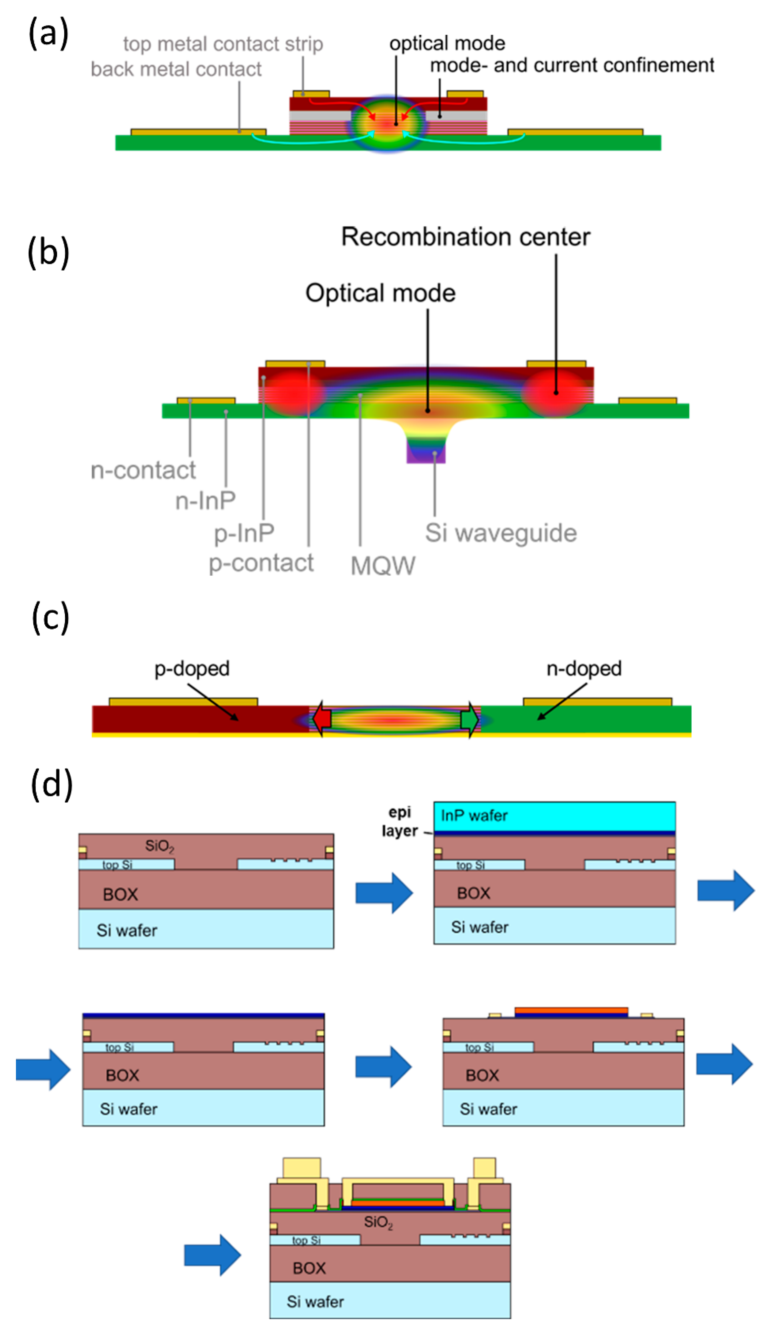
The tight electro-optical integration concept of the switch matrix, as depicted in Figure 2, greatly profits from a monolithic co-integration of the light sources. Though external light sources might be feasible, a direct co-integration provides a much simplified and leaner assembly. Light is generated at the position in the matrix where it is required, in the unit cell depicted in Figure 5. For the co-integration of the light source and the gain material, we explored a novel approach that goes beyond today’s established III–V on silicon photonics concepts [23]. We embed the III–V layer in between the front- and back-end of the line of the silicon stack while the laser feedback structures are integrated into the silicon waveguide layer [24]. This will enable a monolithic co-integration of passive and active photonic functions together with electrical (Bi)CMOS circuits. Several requirements need to be fulfilled to establish a truly CMOS embedded III–V on silicon technology. First, the materials involved must be CMOS compatible. We, therefore, established gold-free electrical contacts to the gain medium [25]. The additional processes related to the integration of the laser must be CMOS compatible. This is especially challenging with respect to the temperature, which should not exceed 600 °C for more than 2 min [26]. This led to our choice to integrate the III–V layer by bonding. Furthermore, the CMOS embedded laser concept puts hard boundary conditions on the geometry. As the III–V gain layer is integrated on top of the first dielectric layer in the back-end-of-the-line stack, its thickness should not exceed about 200 nm. This has severe consequences for the electrical pumping scheme of the lasers, as indicated in Figure 13.
Figure 13a shows a vertical current injection scheme. As the III–V stack has a thickness of only 200 nm, the top electrical contacts are moved to the edge of the mesa to avoid absorption of the optical mode. With this structure, we could demonstrate optically and electrically pumped lasers. The latter work only at low temperatures of 100 K. As indicated by the arrows, a challenge emerges to sustain confinement of the optical mode and the carriers in the center of the structure, which is essential for efficient pumping and high gain [24]. As a result, carriers tend to recombine at the edge of the mesa, thus leading to insufficient gain, which suppresses room temperature (RT) lasing (Figure 13b). Oxidation of the aluminum-containing layers in the quantum well stack, a method successfully applied for vertical cavity surface-emitting lasers, appears to be not reproducible. Research on other carrier confinement concepts is ongoing. We, therefore, also investigate another concept based on lateral current injection as indicated in Figure 13c. This concept is already successfully applied for thin laser stacks [27]. In this case, we regrow the p- and n-doped regions after the etching of the quantum-well mesa. This demands an excellent control of the InP surface and the mesa sidewalls. First, experimental data on detectors is very encouraging [28], and within L3MATRIX, we have confirmed that the InP membrane bonding process can co-exist with AMS ion implantation for the Si side (for E-O modulators), which makes this structure particularly promising.
In addition, we have investigated QD-based active media, suitable for future applications in optical interconnects. While QDs are far less common in the industry than quantum wells and are, therefore, less developed to date, they exhibit certain properties that make them advantageous for certain SiP applications. In fact, SiP would highly benefit from integrated laser sources exhibiting a higher temperature insensitivity combined with a low threshold current. As previously shown, low-dimensional nanostructures may exhibit these properties well owing to their lower density of states and smaller active volumes [29,30,31].
Indeed, QD lasers with a low threshold current [32] and high-temperature insensitivity have been demonstrated in conventional InAs/GaAs diodes (not integrated on Silicon) by several groups, as for example in [33]. In addition, in recent years, significant progress is being made in integrating QDs lasers on CMOS-compatible Si and SOI substrates, either by direct growth or wafer bonding [34] techniques. These attempts have shown some very promising results, such as high-temperature CW operation up to 120 °C, [35] and, more recently, compact photonic crystal designs [36]. These results are very promising, but it should be noted that the high-temperature performance of these Si-based III–V lasers should still be further significantly enhanced at the needed high-temperature regime (>75 °C) if they are to be implemented in future DC architectures, and this is currently being intensively investigated in various settings. In addition to the performance enhancement requirements, QD-based material also exhibited certain additional challenges with respect to co-integration, which we addressed within L3MATRIX.
The first one arises due to the relatively higher refractive index of the InAs/GaAs QD material system compared to InP-based QWell materials [23,24,25]. This made the coupling between the III–V and Si waveguides inefficient for many of the QD III–V structures, so special designs were required. The second major challenge concerned the fact that previous QD demonstrations [29,30,31,32,33] always utilized thick gain stacks (epitaxial III–V thickness > 2 μm) in order to provide sufficient material gain and low losses [37]. From the L3MATRIX perspective, considering thin gain stacks that would be compatible with industrial production lines is highly desirable. However, for QDs, substantially reducing the cladding width was especially challenging due to their lower modal gain as compared to QWells. This means that a very high degree of QD quality and uniformity must be achieved to overcome the additional free carrier absorption losses when they are placed nearer to the highly doped contact layers.
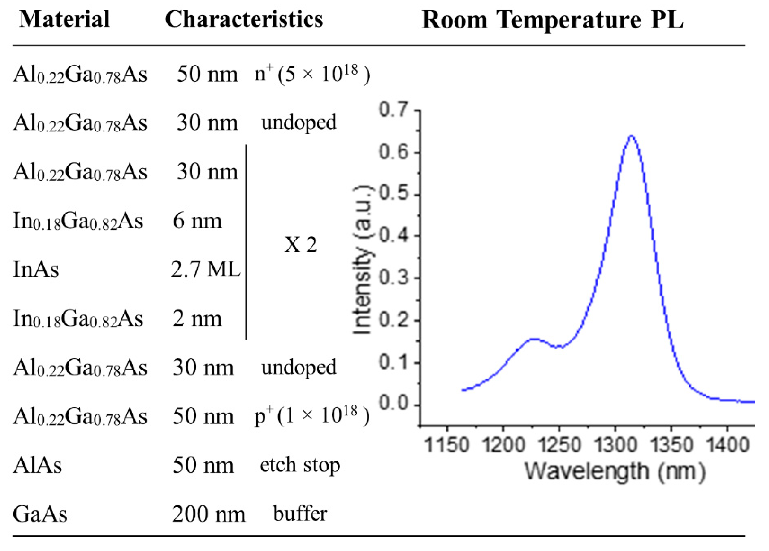
To address these combined challenges, we performed an integrated experimental and theoretical study, including numerical simulations of the III–V to Si coupling using the modelling software CST [38], MBE material growth and material characterization. Initial simulations demonstrated that the coupling efficiency of the conventional stack, in which GaAs intermediate barriers are placed between successively grown QD layers, was very poor. Therefore the barrier material had to be replaced with ternary AlxGa(1−x)As to lower the refractive index of the III–V waveguide (Figure 14). However, AlxGa(1−x)As barriers tend to shift the QD emission toward shorter wavelengths (due to a larger confinement of the electron wave functions) and larger dots are thus needed to compensate for this. The QDs with the original GaAs barriers were already large to achieve the desired emission wavelength at 1.3 μm and growing even larger dots to accommodate the shift would typically cause dislocations within the QD layers. This has been addressed by first optimizing the heterostructure design and subsequently by heavily optimizing the growth conditions. CST simulations were combined with semi-analytical modelling, which helped determine the lowest Al composition in the barriers that resulted in sufficient III–V to Si coupling. To be able to model the mode profiles with higher precision, we obtained very precise measurements of AlxGa(1−x)As refractive indices at 1.3 μm by growing dedicated samples with various compositions (x) and measuring them with spectroscopic ellipsometry [39]. InGaAs QWells and InAs QDs have also been grown and measured separately, and the AlxGa(1−x)As ternaries have been studied on both lattice-matched GaAs substrates and over QWells (strained layers). We grew these individual layers using MBE with identical growth conditions as the final complete gain stacks. Our CST simulations with these values showed that growing a dot-in-a-well (DWell) structure with Al0.22Ga0.78As barriers would provide sufficient coupling, with >75% of the mode coupled to the Si waveguide in the desired regions. This is a satisfactory result due to the moderate Al content needed to be employed, which moderated the aforementioned challenges.
We subsequently optimized the growth conditions to achieve high-quality quantum dot layers. Layer quality was assessed using Photoluminescence (PL) measurements after each growth run. Whilst initial growth runs did not provide any PL signal, optimization enabled a bright PL with a relatively low FWHM. The final sample was grown using MBE and included only 2 QD layers sandwiched between In0.18Ga0.82As QWells and embedded in Al0.22Ga0.78As barriers and waveguide layers. Al0.22Ga0.78As n- and p-doped layers were used as contact layers. The final optimized design that we have grown is detailed in Figure 14; the total III–V gain stack thickness was 236 nm, suitable for integration in the back-end-of-the-line stack.

5. Modulators

5.1. Conventional Modulators

The L3MATRIX integrated transmitter includes electro-optic (E/O) modulators that must be simultaneously compact, high-speed, and ultimately low power to match the ASIC’s output voltage. Moreover, the fabrication process must be kept simple and robust, ensuring that the design rules of a standard CMOS platform, providing commercial electronic integrated circuits (EICs), are met. For these reasons, the active modulator region is a vertical pn junction (Figure 15) that produces a larger effective index change than horizontal (lateral) ones [40]. In addition to their versatility, vertical designs are less sensitive to fabrication variations than conventional ones [41]. L3MATRIX modulators also benefit from the high tolerance to mask alignment inaccuracies because their fabrication depends on the implantation energy rather than lithography resolution. Early vertical pn junctions were based on doped polysilicon deposition [42], which is readily available in standard CMOS processing lines. It is, however, a lossy material. More recently, a “U-shaped” pn junction was demonstrated [43], exhibiting high modulation efficiencies of 4.6 V.mm and 2.6 V.mm at a low voltage at a −0.5 V bias. However, its formation relies on several low-medium energy implantation steps that must be precisely aligned with respect to one another, increasing the overall cost of the process. Moreover, implantation at 0° tilt (instead of 7°) dramatically increases Boron channeling and, hence, decreases the control on the vertical positioning of the junction, which may affect the robustness of the process when the number of fabricated devices scales up. The modulator fabrication was entirely performed in the AMS CMOS foundry (Figure 6) with 248 nm DUV lithography. Most notably, the 1.2 µm wide pn junction was formed with only one mask, reducing simultaneously the cost and the impact of potential alignment errors. Phosphorus (P) was implanted with an energy of 150 keV and a dose reaching 5 × 1013 cm−3 to form the n-type region. BF3 (BF2+) implantation, at 100 keV energy and 4 × 1013 cm−3 dose, was used for the p-type region to benefit from its shallow implantation profile. The p++ and n++ regions were formed with a shallow 20 keV implant with a 1e15 cm−3 dose. The wafer was then annealed for 10 s at 1000 °C in an inert argon (Ar) environment. The high-speed electrodes consist of standard CMOS stacked bi-layers of 500 nm aluminum and 150 nm TiN (anti-reflective coating) (M1 and M2 in Figure 15a,b) interconnected with tungsten (W) vias. The Metal (TiN liner, W)-semiconductor (Ti-Si) silicidation together with the heavily doped p++ and n++ regions led to very low contact resistance, making high-speed operation possible. The travelling wave electrodes design was carried out with HFSS to maximize the overlap and relative speeds of the co-propagating optical and electrical signals. Optimal ohmic contacts between the W vias and the SOI region were achieved using a 1 × 1015 cm−3 dose and a shallow 20 keV implant to form the p++ and n++ regions.
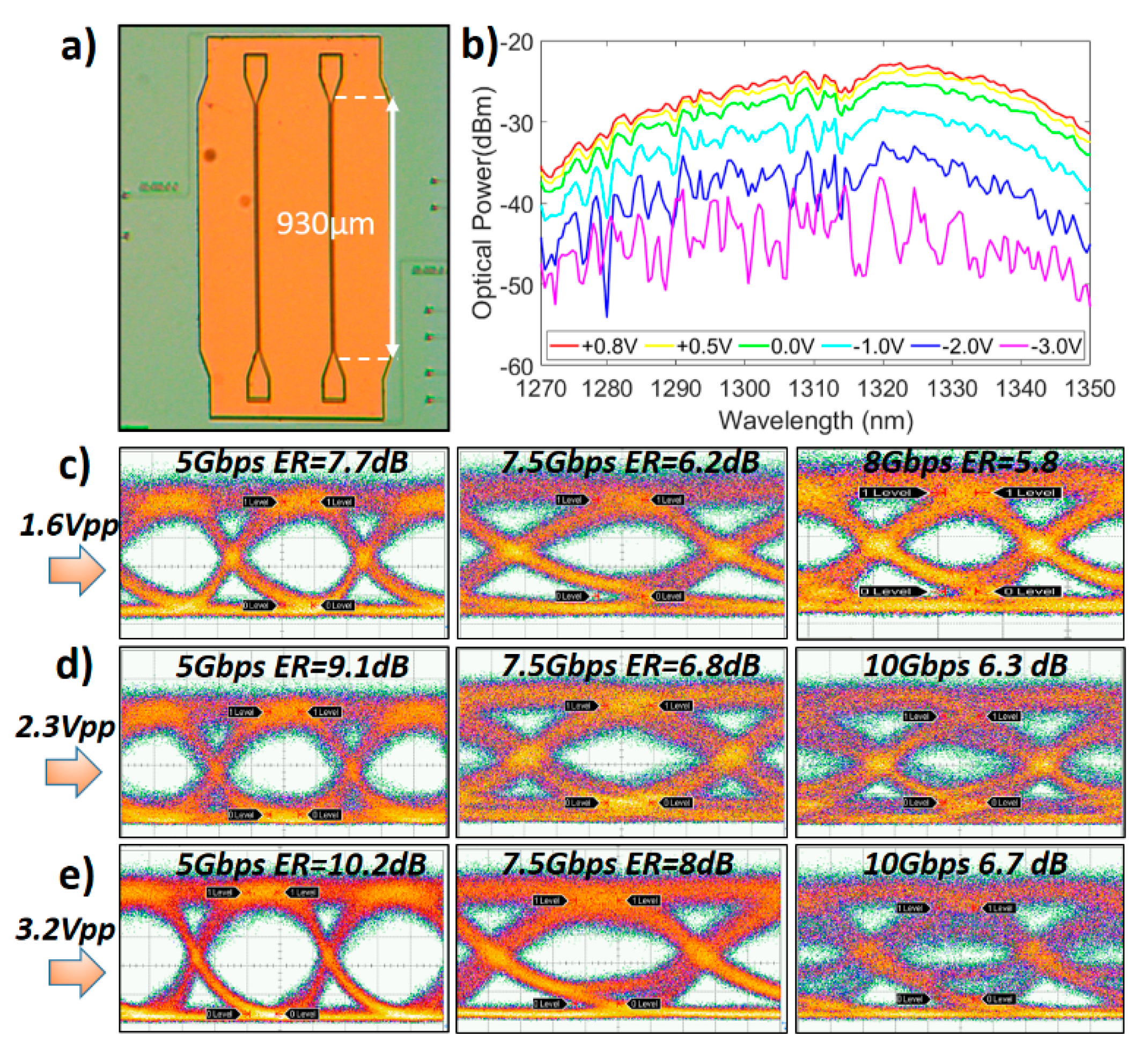
The travelling wave modulators were electro-optically characterized as standalone devices in DC and AC (Figure 16) using a bit pattern generator (SHF BPG 44E) delivering a non-return-to-zero pseudo-random bit sequence (NRZ PRBS−1) of the length 231-1, with 1.6 Vpp, 2.3 Vpp and 3.2 Vpp applied in a push-pull (differential) manner. The symmetric nature of the modulators makes their operation less wavelength-dependent than their asymmetric counterparts. For a 930 µm long phase-shifter, a π-phase shift is achieved at a 4 V variation, leading to an estimated VπL of 0.35–0.40 V.cm and positioning our modulator among the state-of-the-art compared to other devices working in the “O-band” [44,45]. The insertion losses produced by the 0.93 mm-long active (doped) arms of the Mach–Zehnder are around 4.6 dB (≈5 dB/mm) due to higher doping values. 10 Gb/s data transmission with enough extinction ratio to allow direct detection of the modulated signal is demonstrated with low differential drive voltages applied on the sub-mm E/O device. A small signal analysis reveals that the speed limitation arises from the microwave losses and reflections produced by the 2-layers back-end metal stack, which encompasses Al layers sandwiched between resistive TiN layers. Further improvements of the metals stack should, therefore, readily enable data transmission in the range of >25 Gb/s, getting closer to the pn junction intrinsic bandwidth.

5.2. Slow Light Modulators

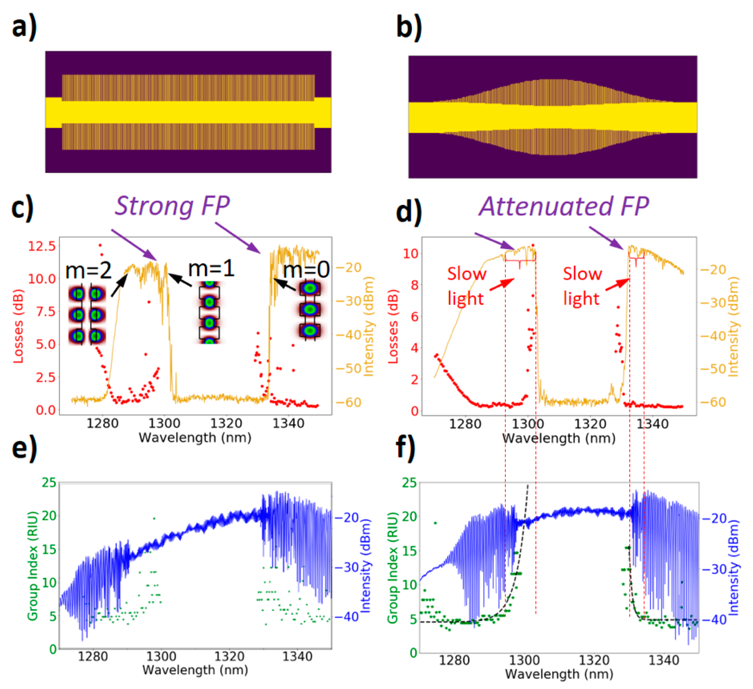
To increase the modulation efficiency, the use of slow light structures combined with any given refractive index change mechanism allows a higher level of interaction between light and matter. This enhancement is directly proportional to the increase in group index (or decrease in group velocity) with respect to conventional waveguides. Slow light modulators are far more complex than their conventional (rib-waveguide-based) counterparts. Indeed, to minimize unwanted reflections and prohibitive insertion loss, slow light modulators require additional efforts to achieve smooth optical transitions between “fast-light” (rib/strip-waveguides) and “slow-light” sections (corrugated waveguide). Figure 17 illustrates the improvement of using adiabatic tapers generated by using a Blackman apodization function. This simultaneously reduces the Fabry–Pérot resonances produced by the reflecting input/output of the slow light waveguide and losses at moderate group index values (up to 20) with respect to the unapodized version of the waveguide.
The modulation efficiency enhancement is directly proportional to the slow down factor, i.e., the ratio of the group index in the slow light region and that in the fast light region (s = ng,slow light/ng,fast light). The maximum experimentally measured group index (ng = 20) here leads to a slow down factor of 5, which enables a size reduction of the modulator by the same factor, while the losses follow a linear or even sub-linear [46] trend versus group index. Based on the efficiency of the conventional modulator, the slow version would be 5 times shorter (186 µm) with similar losses, provided that a suitable tapering section such as the one proposed in Figure 17 is used.
Moreover, it is of paramount importance that the optical group velocity matches the electrical group velocity. This mismatch may significantly alter the E/O bandwidth in certain conditions (note Section 6.1). While the slowdown of the group velocity of the propagating light is achievable with properly designed slow light structures, the slowdown of the group velocity of the electrical wave is not as straightforward. To solve this issue, the electrical group index must match the optical group index, i.e., both electrical and optical waves must travel at the same speed in a travelling wave configuration. Through the combination of inductive and capacitive elements, a microwave index up to 11.6 has been demonstrated at 40 GHz and beyond while keeping the impedance value close to 50 Ω. This value is the largest to date obtained in planar transmission lines [47].
Overall, we have shown various aspects of slow light modulators and found solutions for achieving low losses, low Fabry–Pérot resonances via adiabatic slow-light tapers, as well as slow-wave electrodes to keep benefiting from the high slow light modulator efficiency at high frequencies. The fabrication of fully integrated slow light modulators is currently in the final stage.

6. 3D Integration and Assembly

A vertical assembly approach was selected for the L3MATRIX device shown schematically in Figure 2. This design ensures that every modulator or photodiode is assembled directly above their driver or trans-impedance amplifier (TIA), thus minimizing parasitic impedances on the transmission line. The analog drivers are, thus, integrated into the chiplet ASIC along with any digital logic blocks required for the task. A substrate is used in this design to connect the CMOS chip to the system PCB. This board is a second, large package used to support the high-frequency links between the chiplet and the switch ASICs. In this project, we demonstrate the chiplet assembly and have designed the device to be a stand-alone unit. In an actual co-package application, all the ASICs (chiplets + switch) will be assembled on a single substrate.

6.1. RF Modulator Electrodes Design

Prior to assembly, SiP wafers must be post-processed in order to receive bonding pads that are compatible with the solder reflow assembly process. Furthermore, this metallization will be the metallization of the electrodes of the modulators and should not lead to a deterioration of the performance of the devices. For this purpose, simulations of the RF performance have been conducted to carefully design the electrodes.
The implementation of the L3MATRIX technology requires the use of travelling wave (TW) electrodes, which are essential to achieve the high bandwidth requested by DCs. The downside of combining slow light with a travelling wave design is the mismatch between the microwave group index and the optical one [48]. For a lossless modulator with impedance matched load and generator, the 3 dB modulation bandwidth is given by:
f 3 dB = 0.18 l ( n m n 0 )     ( GHz )
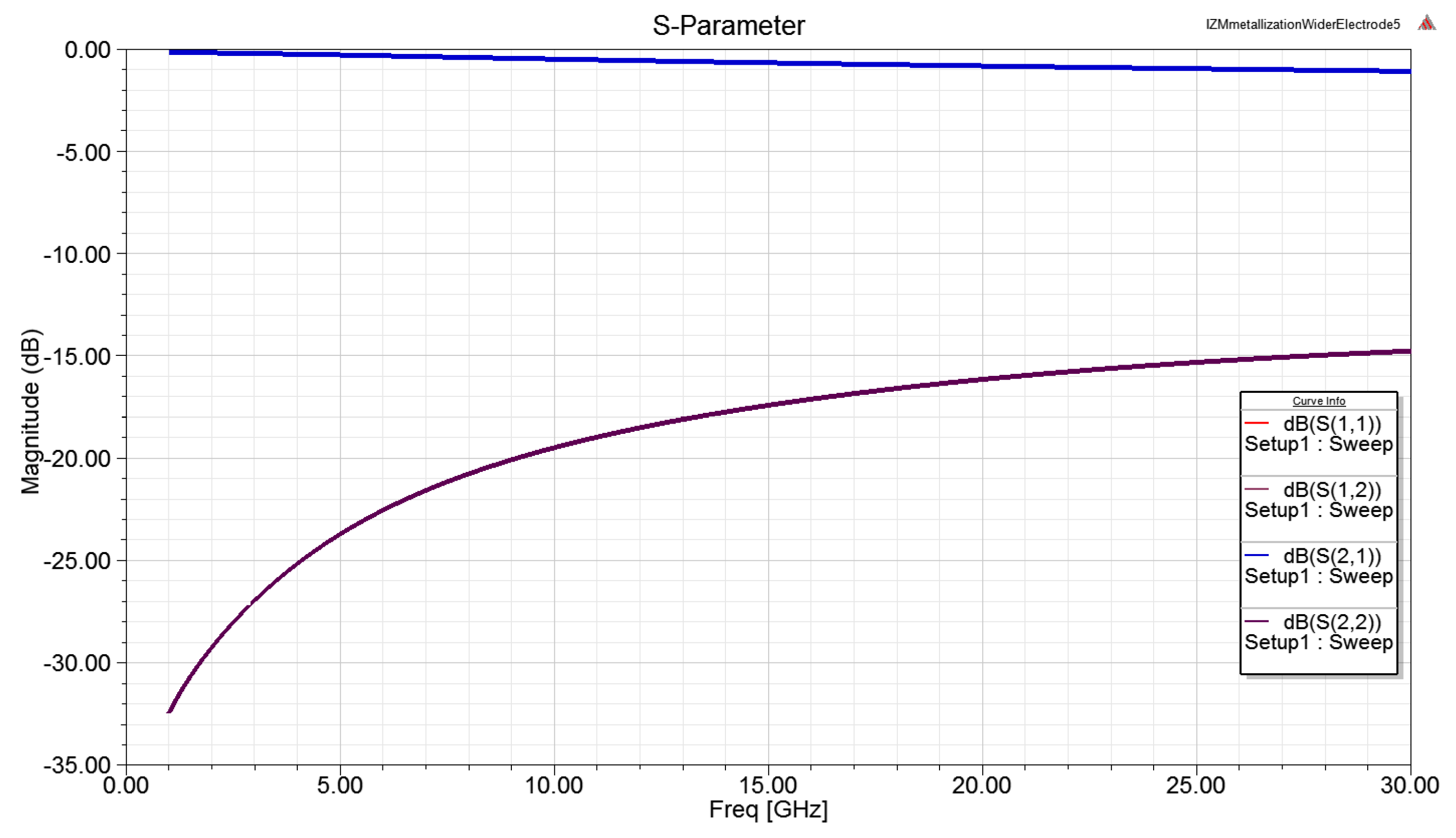
where l is the electrode length, nm is the microwave refractive index, and n0 is the group refractive index of the optical mode. In our case, taking a 0.5 mm long electrode, a microwave refractive index of 3.8 at 30 GHz and optical group indices of 10, 15 and 20 lead to a 3 dB bandwidth roll-off of 57, 32 and 22 GHz, respectively. Therefore, for a sufficiently short modulator, the velocity mismatch arising from the use of slow light is not impairing the high-speed performance of the modulator. A symmetrical travelling wave electrode based on a ground-signal-ground (GSG) coplanar strip waveguide (CPW) transmission line has been designed using the commercial finite element method solver for electromagnetic structures, ANSYS HFSS. Considering the metal stack present on the SiP wafers, S-parameters can be simulated and are shown in Figure 18.
These calculated values show that electrodes compatible with the targeted performance and solder reflow processes can be fabricated for the L3MATRIX devices.

6.2. SiP Chip Assembly on a Silicon Interposer

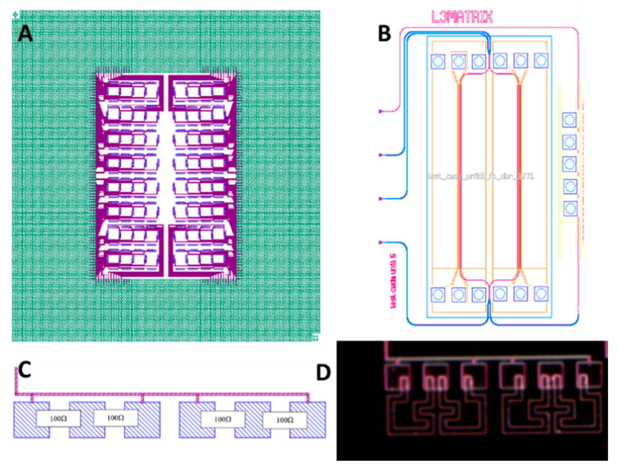
An actual mixed signal chiplet was not available to the project as their design would be part of a full co-package solution. We, thus, used a silicon interposer to mimic the functionality and integration of the real chiplet. This interposer, shown in Figure 19, is 24 × 24 mm and has two functional areas. In the center of the die, there are 64 unit cells, one for each SiP transmit unit. In each cell, there are GSG bumps for the RF modulator as well as 100 Ω terminations. The integrated laser has GSG DC supply bumps and two additional thermal bumps used to assist in heat removal from the laser. The GND and thermal bumps are connected to different planes in the package to avoid shorts. Most of the die (green area in Figure 19) has about 11,000 SAC bumps mimicking an actual CMOS chip.
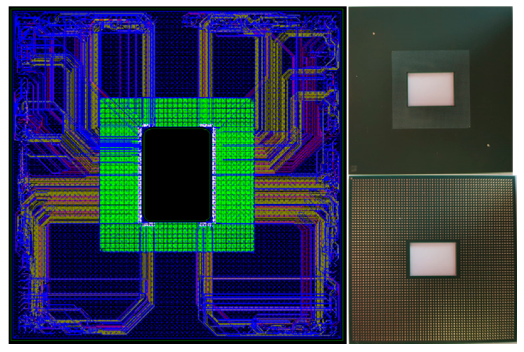
These are dummy bumps used for mechanical support. The package design is an organic substrate used to connect the interposer to the system package. A cutout hole is made in the center to facilitate optical coupling to the device, Figure 20. This is a 50 × 50 mm coreless substrate with RF routing via several planes to connect the SiP modulator driver output to the modulator bumps on the interposer.

6.3. Matrix Vertical Fiber Coupling

Fiber coupling is one of the major problems associated with a co-package system [49,50]. The challenge is to develop a fiber connector that will enable coupling to 16 single-mode fibers simultaneously and that can be assembled on a high-volume scale. The design used is a vertical coupling as dictated by the assembly and integration scheme of the L3MATRIX device. A two-lens relay approach is used with one lens on the back surface of the SiP and the second lens on the fiber array. Light is reflected by the grating coupler (Figure 11) through the BOX and the silicon substrate. The emerging beam is tilted at 10°, and the lens design was carried out such that the light path is rotated back to the normal axis, Figure 21. The lenses are in a 2 × 8 layout as dictated by the SiP layout. The first lens array is a flip-chip assembled on the back surface of the SiP die using alignment marks. The second lens array is aligned with a fiber array and aligned to the lower array actively. A fully passive alignment of 16 single-mode fibers remains still a significant challenge.

7. Discussion and Future Perspective

The challenges addressed by the L3MATRIX project are typical of those that will be found in the design of a co-packaged system. We can divide them into two groups: photonic and packaging. The former includes all aspects of the large two-dimensional SiP array, while the latter involves the packaging of the photonic device in a chiplet as part of the larger system.

7.1. Photonic Device

Moving the optical interconnect from the switch front panel to the vicinity of the switch ASIC requires the fabrication of an I/O-specific chiplet. There are several designs used in different chiplet applications ranging from discrete, 4-lane SiP arrays to large 64-lanes devices, as described here. In terms of fabrication complexity, it is evident that the former approach shows better yield and process simplicity. However, the stringent space/power limitations expected in an actual 51 Tb/s switch favor the grouping of the optical devices in one large array that will enable both power and space-saving resulting from the combined device overhead.
All L3Matrix components have been designed having two important restrictions in mind: in terms of compatibility with high-volume manufacturing and with the CMOS technology. To this end, we have strictly utilized only CMOS-compatible materials and fabrication processes, and we have worked in close collaboration with AMS AG to only use processes that are compatible with their high-volume fabrication protocols.
The L3Matrix co-packaging technology demonstrated here is very versatile, and it can be potentially combined with other technologies, for example, with a 100 Gb/s modulation to intersect the 51 Tb/s switch generation in the future.
It is worth mentioning that, moving one step further, we have exploited the optical devices designed in L3MATRIX to develop a novel high-radix optical packet switch (OPS) architecture, named ‘Hipoλaos’ [51]. This architecture provides low latency, high bandwidth and high radix connectivity towards meeting the requirements of End-of-Row (EoR) network architectures, and its feasibility is well documented in the literature [51,52,53,54,55,56,57,58]. As a result, the proposed architecture can, by leveraging the L3MATRIX large-scale SiP matrix with its low-power and low-cost credentials, lead to considerable power savings in conjunction with a significant decrease in the number of DC switching layers.
Regarding the light source, there are two accepted approaches-integrated and external. Both have their pros and cons, specifically regarding thermal stability in the vicinity of the hot switch ASIC and assembly. We have decided to investigate the integrated approach as it allows for efficient packaging that can be scaled even further to larger SiP matrices. Compared to the external laser source approach, integrated lasers have a ~6 dB advantage in power efficiency as the coupling of light to and from the fiber is not required. The downside of this design is the reduced lifetime of the laser and its thermal instability. Reliability issues can be solved by the addition of redundant lasers to each cell or the same wavelength cell rows (see Figure 4 and Figure 5). The lasers can be connected to each other using an MMI with the redundant laser enabled upon monitoring the degradation of the active one. The thermal instability issue is more difficult to handle. We have added ‘dummy’ laser structures on each CWDM row (4 cells) to compensate for thermal drifts. These problems are obviously not present with external laser banks, and more experimentation is required to address this problem.

7.2. Device Package

The packaging scheme used in L3MATRIX was carried out as an investigation into the design of a switch I/O chiplet. With the decision to fabricate large SiP arrays, a package method is needed to support such arrays efficiently. While vertical assembly has clear benefits in terms of signal integrity and space/power efficiency, it dictates a vertical fiber coupling scheme which is still complicated to perform. Edge coupling of the fibers is more suited to commercial automated assembly machines and may have some advantages now. However, we have shown that eventually, a vertical approach may be possible.
The advantage of a vertical assembly scheme is especially evident if the chiplet is designed as a mixed-signal chip with some logic blocks transferred to it from the switch. Such blocks may be the MAC, FEC and redundancy handling macros. Other functions can be off-loaded as well. In such a case, the chiplet die size can become large such that a vertical coupling is the only reasonable assembly method due to the limited space on the package.

8. Conclusions

In conclusion, we reported the recent advances introduced by the L3MATRIX project in Silicon Photonics and in photonic-electronic integration. Our advances in the areas of system architecture and design, light sources, fabrication of individual Silicon Photonics components and conventional and slow-light modulators provide a toolbox of technologies and architectures to address related challenges. All parts have been designed having two important restrictions in mind: compatibility with high-volume manufacturing and with the CMOS technology. In addition, we have developed our strategy for a full 3D vertical assembly approach and our proposed system architecture. We highlighted its motivation in view of the challenges described to introduce considerable power and cost savings in conjunction with a significant decrease in the number of DC switching layers in a co-packaged system. Progress and open questions based on the technical status of the project are discussed in detail as well. Our results provide a step toward future low-power and low-cost Data Centers.

Author Contributions

Conceptualization, K.H. and A.M.; silicon photonics, J.K. and V.S.; mask layout integration and design methodology, K.L. and R.G.B.; quantum well light sources, M.S., Y.B., F.H. and B.J.O.; quantum dot light sources, K.P., D.R.S., M.T., A.J.S. and H.L.; modulators, A.B., A.Z. and P.S.; RF modulator electrodes design, B.S., Y.E., H.O. and T.T.; system testing, N.T., G.M.-A., M.M.-P., T.M., N.P. and K.V.; system integration and assembly, K.H. and A.M.; coordination of reporting current results, K.P. and D.R.S.; general project coordination B.S., T.T. All authors have read and agreed to the published version of the manuscript.

Funding

The L3MATRIX project is co-funded by the Horizon 2020 Framework Programme of the European Union with Grant Agreement Nr. 688544. L3MATRIX project is an initiative of the Photonics Public Private Partnership.

Institutional Review Board Statement

Not applicable.

Informed Consent Statement

Not applicable.

Data Availability Statement

The data that support the findings of this study are available from the corresponding authors upon reasonable request.

Conflicts of Interest

The authors declare no conflict of interest.

References

  1. Greenberg, A.; Hamilton, J.R.; Jain, N.; Kandula, S.; Kim, C.; Lahiri, P.; Maltz, D.A.; Patel, P.; Sengupta, S. VL2: A scalable and flexible data center network. SIGCOMM Comput. Commun. Rev. 2009, 39, 51–62. [Google Scholar] [CrossRef]
  2. Cheng, Q.; Bahadori, M.; Glick, M.; Rumley, S.; Bergman, K. Recent advances in optical technologies for data centers: A review. Optica 2018, 5, 1354–1370. [Google Scholar] [CrossRef]
  3. Buscaino, B.; Taylor, B.D.; Kahn, J.M. Multi-Tb/s-per-Fiber Coherent Co-Packaged Optical Interfaces for Data Center Switches. J. Light. Technol. 2019, 37, 3401–3412. [Google Scholar] [CrossRef]
  4. Al-Fares, M.; Loukissas, A.; Vahdat, A. A scalable, commodity data center network architecture. ACM SIGCOMM Comput. Commun. Rev. 2008, 38, 63–74. [Google Scholar] [CrossRef]
  5. Bernabé, S.; Wilmart, Q.; Hasharoni, K.; Hassan, K.; Thonnart, Y.; Tissier, P.; Désières, Y.; Olivier, S.; Tekin, T.; Szelag, B. Silicon photonics for terabit/s communication in data centers and exascale computers. Solid-State Electron. 2021, 179, 107928. [Google Scholar] [CrossRef]
  6. Hasharoni, K.; Benjamin, S.; Geron, A.; Stepanov, S.; Katz, G.; Epstein, I.; Margalit, N.; Chairman, D.; Mesh, M. A 1.3 Tb/s parallel optics VCSEL link. In Optical Interconnects XIV; SPIE Press–International Society for Optics and Photonics: Bellingham, WA, USA, 2014; p. 89910C. [Google Scholar]
  7. Minkenberg, C.; Farrington, N.; Zilkie, A.; Nelson, D.; Lai, C.P.; Brunina, D.; Byrd, J.; Chowdhuri, B.; Kucharewski, N.; Muth, K.; et al. Reimagining datacenter topologies with integrated silicon photonics. J. Opt. Commun. Netw. 2018, 10, B126–B139. [Google Scholar] [CrossRef]
  8. Aoki, T.; Sekiguchi, S.; Simoyama, T.; Tanaka, S.; Nishizawa, M.; Hatori, N.; Sobu, Y.; Sugama, A.; Akiyama, T.; Hayakawa, A.; et al. Low-Crosstalk Simultaneous 16-Channel × 25 Gb/s Operation of High-Density Silicon Photonics Optical Transceiver. J. Light. Technol. 2018, 36, 1262–1267. [Google Scholar] [CrossRef]
  9. De Dobbelaere, P.; Dahl, A.; Mekis, A.; Chase, B.; Weber, B.; Welch, B.; Foltz, D.; Armijo, G.; Masini, G.; McGee, G.; et al. Advanced silicon photonics technology platform leveraging a semiconductor supply chain. In Proceedings of the 2017 IEEE International Electron Devices Meeting (IEDM), San Francisco, CA, USA, 2–6 December 2017; pp. 34.1.1–34.1.4. [Google Scholar]
  10. Stojanović, V.; Ram, R.J.; Popović, M.; Lin, S.; Moazeni, S.; Wade, M.; Sun, C.; Alloatti, L.; Atabaki, A.; Pavanello, F.; et al. Monolithic silicon-photonic platforms in state-of-the-art CMOS SOI processes. Opt. Express 2018, 26, 13106–13121. [Google Scholar] [CrossRef] [Green Version]
  11. L3MATRIX. Available online: https://l3matrix.eu/ (accessed on 1 June 2021).
  12. Shen, X.; Chen, B.; Zhu, Y.; Shi, W. Silicon photonic integrated circuits and its application in data center. In Proceedings of the 7th Symposium on Novel Photoelectronic Detection Technology and Applications, Kunming, China, 5–7 November 2020; Volume 11763, p. 1176380. [Google Scholar]
  13. Luxtera (Now Cisco). Mid-Board Optic Transceivers. Available online: http://www.luxtera.com/embedded-optics/ (accessed on 1 June 2021).
  14. Maniotis, P.; Terzenidis, N.; Siokis, A.; Christodoulopoulos, K.; Varvarigos, E.; Immonen, M.; Yan, H.J.; Zhu, L.X.; Hasharoni, K.; Pitwon, R.; et al. Application-Oriented On-Board Optical Technologies for HPCs. J. Light. Technol. 2017, 35, 3197–3213. [Google Scholar] [CrossRef]
  15. Bernabe, S.; Rida, K.; Pares, G.; Castany, O.; Fowler, D.; Kopp, C.; Waltener, G.; Jimenez, J.L.G.; Menezo, S. On-Board Silicon Photonics-Based Transceivers With 1-Tb/s Capacity. IEEE Trans. Compon. Packag. Manuf. Technol. 2016, 6, 1018–1025. [Google Scholar] [CrossRef]
  16. Bogaerts, W.; Chrostowski, L. Silicon photonics circuit design: Methods, tools and challenges. Laser Photonics Rev. 2018, 12, 1700237. [Google Scholar] [CrossRef]
  17. Nazca-Design. Available online: Nazca-design.org (accessed on 9 April 2021).
  18. Papakonstantinou, I.; James, R.; Selviah, D.R. Radiation and bound-mode propagation in rectangular, multimode dielectric, channel waveguides with sidewall roughness. J. Light. Technol. 2009, 27, 4151–4163. [Google Scholar] [CrossRef] [Green Version]
  19. Cai, J.; Lim, P.H.; Ishikawa, Y.; Wada, K. Silicon waveguide sidewall smoothing by resist reflowing. J. Nonlinear Opt. Phys. Mater. 2010, 19, 801–809. [Google Scholar] [CrossRef]
  20. Gao, F.; Wang, Y.; Cao, G.; Jia, X.; Zhang, F. Improvement of sidewall surface roughness in silicon-on-insulator rib waveguides. Appl. Phys. A 2005, 81, 691–694. [Google Scholar] [CrossRef]
  21. Wang, P.; Michael, A.; Kwok, C.Y. Fabrication of sub-micro silicon waveguide with vertical sidewall and reduced roughness for low loss applications. Procedia Eng. 2014, 87, 979–982. [Google Scholar] [CrossRef] [Green Version]
  22. Horst, F.; Green, W.; Offrein, B.; Vlasov, Y. Silicon-on-Insulator Echelle Grating WDM Demultiplexers with Two Stigmatic Points. IEEE Photonics Technol. Lett. 2009, 21, 1743–1745. [Google Scholar] [CrossRef]
  23. Fang, A.W.; Park, H.; Cohen, O.; Jones, R.; Paniccia, M.J.; Bowers, J.E. Electrically pumped hybrid AlGaInAs-silicon evanescent laser. Opt. Express 2006, 14, 9203–9210. [Google Scholar] [CrossRef]
  24. Seifried, M.; Villares, G.; Baumgartner, Y.; Hahn, H.; Halter, M.; Horst, F.; Caimi, D.; Caër, C.; Sousa, M.; Dangel, R.F.; et al. Monolithically Integrated CMOS-Compatible III–V on Silicon Lasers. IEEE J. Sel. Top. Quantum Electron. 2018, 24, 1–9. [Google Scholar] [CrossRef] [Green Version]
  25. Hahn, H.; Sousa, M.; Czornomaz, L. Low-resistive, CMOS-compatible ohmic contact schemes to moderately doped n-InP. J. Phys. D Appl. Phys. 2017, 50, 235102. [Google Scholar] [CrossRef]
  26. Batude, P.; Fenouillet-Beranger, C.; Pasini, L.; Lu, V.; Deprat, F.; Brunet, L.; Sklenard, B.; Piegas-Luce, F.; Casse, M.; Mathieu, B.; et al. 3DVLSI with CoolCube process: An alternative path to scaling. In Proceedings of the 2015 Symposium on VLSI Technology, Kyoto, Japan, 15–18 June 2015; pp. T48–T49. [Google Scholar]
  27. Fujii, T.; Takeda, K.; Diamantopoulos, N.-P.; Kanno, E.; Hasebe, K.; Nishi, H.; Nakao, R.; Kakitsuka, T.; Matsuo, S. Heterogeneously Integrated Membrane Lasers on Si Substrate for Low Operating Energy Optical Links. IEEE J. Sel. Top. Quantum Electron. 2017, 24, 1–8. [Google Scholar] [CrossRef]
  28. Baumgartner, Y.; Seifried, M.; Caër, C.; Stark, P.; Caimi, D.; Faist, J.; Offrein, B.; Czornomaz, L. Novel CMOS-Compatible Ultralow Capacitance Hybrid III-V/Si Photodetectors Tested up to 32 Gbps NRZ. In Proceedings of the Optical Fiber Communication Conference (OFC), San Diego, CA, USA, 3–7 March 2019; pp. 1–3. [Google Scholar]
  29. Papatryfonos, K.; Rodary, G.; David, C.; Lelarge, F.; Ramdane, A.; Girard, J.-C. One-Dimensional Nature of InAs/InP Quantum Dashes Revealed by Scanning Tunneling Spectroscopy. Nano Lett. 2015, 15, 4488–4497. [Google Scholar] [CrossRef]
  30. Papatryfonos, K.; Saladukha, D.; Merghem, K.; Joshi, S.; Lelarge, F.; Bouchoule, S.; Kazazis, D.; Guilet, S.; Le Gratiet, L.; Ochalski, T.J.; et al. Laterally coupled distributed feedback lasers emitting at 2 μm with quantum dash active region and high-duty-cycle etched semiconductor gratings. J. Appl. Phys. 2017, 121, 053101. [Google Scholar] [CrossRef]
  31. Papatryfonos, K.; Joshi, S.; Merghem, K.; Bouchoule, S.; Guilet, S.; Le Gratiet, L.; Martinez, A.; Ramdane, A. Quantum dash based lasers for gas sensing. In Proceedings of the 26th International Conference on Indium Phosphide and Related Materials (IPRM), Montpellier, France, 11–15 May 2014; pp. 1–2. [Google Scholar]
  32. Mukai, K.; Nakata, Y.; Otsubo, K.; Sugawara, M.; Yokoyama, N.; Ishikawa, H. 1.3-/spl mu/m CW lasing characteristics of self-assembled InGaAs-GaAs quantum dots. IEEE J. Quantum Electron. 2000, 36, 472–478. [Google Scholar] [CrossRef]
  33. Gerschutz, F.; Fischer, M.; Koeth, J.; Chacinski, M.; Schatz, R.; Kjebon, O.; Kovsh, A.; Krestnikov, I.; Forchel, A. Temperature insensitive 1.3 µm InGaAs/GaAs quantum dot distributed feedback lasers for 10 Gbit/s transmission over 21 km. Electron. Lett. 2006, 42, 1457. [Google Scholar] [CrossRef]
  34. Hu, Y.; Liang, D.; Mukherjee, K.; Li, Y.; Zhang, C.; Kurczveil, G.; Huang, X.; Beausoleil, R.G. III/V-on-Si MQW lasers by using a novel photonic integration method of regrowth on a bonding template. Light Sci. Appl. 2019, 8, 1–9. [Google Scholar] [CrossRef]
  35. Chen, S.; Li, W.; Wu, J.; Jiang, Q.; Tang, M.; Shutts, S.; Elliott, S.N.; Sobiesierski, A.; Seeds, A.; Ross, I.; et al. Electrically pumped continuous-wave III–V quantum dot lasers on silicon. Nat. Photonics 2016, 10, 307–311. [Google Scholar] [CrossRef]
  36. Zhou, T.; Tang, M.; Xiang, G.; Xiang, B.; Hark, S.; Martin, M.; Baron, T.; Pan, S.; Park, J.-S.; Liu, Z.; et al. Continuous-wave quantum dot photonic crystal lasers grown on on-axis Si(001). Nat. Commun. 2020, 11, 1–7. [Google Scholar] [CrossRef] [Green Version]
  37. Wang, J.; Bai, Y.; Liu, H.; Cheng, Z.; Tang, M.; Chen, S.; Wu, J.; Papatryfonos, K.; Liu, Z.; Huang, Y. Optimization of 1.3 μm InAs/GaAs quantum dot lasers epitaxially grown on silicon: Taking the optical loss of metamorphic epilayers into account. Laser Phys. 2018, 28, 126206. [Google Scholar] [CrossRef]
  38. D’Auria, M.; Otter, W.J.; Hazell, J.; Gillatt, B.T.W.; Long-Collins, C.; Ridler, N.M.; Lucyszyn, S. 3-D Printed Metal-Pipe Rectangular Waveguides. IEEE Trans. Compon. Packag. Manuf. Technol. 2015, 5, 1339–1349. [Google Scholar] [CrossRef] [Green Version]
  39. Papatryfonos, K.; Angelova, T.; Brimont, A.; Reid, B.; Guldin, S.; Smith, P.R.; Tang, M.; Li, K.; Seeds, A.J.; Liu, H.; et al. Refractive indices of MBE-grown AlxGa(1−x) As ternary alloys in the transparent wavelength region. AIP Adv. 2021, 11, 025327. [Google Scholar] [CrossRef]
  40. Watts, M.R.; Zortman, W.A.; Trotter, D.C.; Young, R.W.; Lentine, A.L. Low-voltage, compact, depletion-mode, silicon machzehnder modulator. IEEE J. Sel. Top. Quantum Electron. 2010, 16, 159–164. [Google Scholar] [CrossRef]
  41. Zanzi, A.; Vagionas, C.; Griol, A.; Rosa, A.; Lechago, S.; Moralis-Pegios, M.; Vyrsokinos, K.; Pleros, N.; Kraft, J.; Sidorov, V.; et al. Alignment tolerant low voltage 0.23 V.cm push-pull silicon photonic switches based on a vertical pn junction. Opt. Express 2019, 27, 32409–32426. [Google Scholar] [CrossRef] [PubMed]
  42. Liu, A.; Liao, L.; Rubin, D.; Nguyen, H.; Ciftcioglu, B.; Chetrit, Y.; Izhaky, N.; Paniccia, M. High-speed optical modulation based on carrier depletion in a silicon waveguide. Opt. Express 2007, 15, 660–668. [Google Scholar] [CrossRef]
  43. Yong, Z.; Sacher, W.D.; Huang, Y.; Mikkelsen, J.C.; Yang, Y.; Luo, X.; Dumais, P.; Goodwill, D.; Bahrami, H.; Lo, P.G.-Q.; et al. U-shaped PN junctions for efficient silicon Mach-Zehnder and microring modulators in the O-band. Opt. Express 2017, 25, 8425–8439. [Google Scholar] [CrossRef] [Green Version]
  44. Streshinsky, M.; Ding, R.; Liu, Y.; Novack, A.; Yang, Y.; Ma, Y.; Tu, X.; Chee, E.K.S.; Lim, A.E.-J.; Lo, P.G.-Q.; et al. Low power 50 Gb/s silicon traveling wave Mach-Zehnder modulator near 1300 nm. Opt. Express 2013, 21, 30350–30357. [Google Scholar] [CrossRef] [PubMed]
  45. Perez-Galacho, D.; Baudot, C.; Hirtzlin, T.; Messaoudène, S.; Vulliet, N.; Crozat, P.; Boeuf, F.; Vivien, L.; Marris-Morini, D. Low voltage 25 Gbps silicon Mach-Zehnder modulator in the O-band. Opt. Express 2017, 25, 11217–11222. [Google Scholar] [CrossRef]
  46. O’Faolain, L.; White, T.; O’Brien, D.; Yuan, X.; Settle, M.D.; Krauss, T.F. Dependence of extrinsic loss on group velocity in photonic crystal waveguides. Opt. Express 2007, 15, 13129–13138. [Google Scholar] [CrossRef]
  47. Rosa, A.; Verstuyft, S.; Brimont, A.; Van Thourhout, D.; Sanchis, P. Microwave index engineering for slow-wave coplanar waveguides. Sci. Rep. 2018, 8, 5672. [Google Scholar] [CrossRef] [PubMed] [Green Version]
  48. Hui, Y.; Bogaerts, W. An equivalent circuit model of the traveling wave electrode for carrier-depletion-based silicon optical modulators. J. Light. Technol. 2012, 30, 1602–1609. [Google Scholar] [CrossRef] [Green Version]
  49. Pitwon, R.C.A.; Kai, W.; Graham-Jones, J.; Papakonstantinou, I.; Baghsiahi, H.; Offrein, B.J.; Dangel, R.; Milward, D.; Selviah, D.R. FirstLight: Pluggable optical interconnect technologies for polymeric electro-optical printed circuit boards in data centers. J. Light. Technol. 2012, 30, 3316–3329. [Google Scholar] [CrossRef] [Green Version]
  50. Papakonstantinou, I.; Selviah, D.R.; Pitwon, R.C.A.; Milward, D. Low-cost, precision, self-alignment technique for coupling laser and photodiode arrays to polymer waveguide arrays on multilayer PCBs. IEEE Trans. Adv. Packag. 2008, 31, 502–511. [Google Scholar] [CrossRef]
  51. Terzenidis, N.; Moralis-Pegios, M.; Mourgias-Alexandris, G.; Vyrsokinos, K.; Pleros, N. High-port low-latency optical switch architecture with optical feed-forward buffering for 256-node disaggregated data centers. Opt. Express 2018, 26, 8756–8766. [Google Scholar] [CrossRef]
  52. Spanke, R.A. Architectures for large nonblocking optical space switches. IEEE J. Quantum Electron. 1986, 22, 964–967. [Google Scholar] [CrossRef]
  53. Moralis-Pegios, M.; Moralis-Pegios, M.; Mourgias-Alexandris, G.; Terzenidis, N.; Cherchi, M.; Harjanne, M.; Aalto, T.; Miliou, A.; Pleros, N.; Vyrsokinos, K. On-chip SOI delay line bank for optical buffers and time slot interchangers. IEEE Photonics Technol. Lett. 2017, 30, 31–34. [Google Scholar] [CrossRef]
  54. Spyropoulou, M.; Pleros, N.; Vyrsokinos, K.; Apostolopoulos, D.; Bougioukos, M.; Petrantonakis, D.; Miliou, A.; Avramopoulos, H. 40 Gb/s NRZ Wavelength Conversion using a Differentially-Biased SOA-MZI: Theory and Experiment. J. Light. Technol. 2011, 29, 1489–1499. [Google Scholar] [CrossRef]
  55. Terzenidis, N.; Moralis-Pegios, M.; Mourgias-Alexandris, G.; Alexoudi, T.; Vyrsokinos, K.; Pleros, N. High-Port and Low-Latency Optical Switches for Disaggregated Data Centers: The Hipoλaos Switch Architecture. J. Opt. Commun. Netw. 2018, 10, B102–B116. [Google Scholar] [CrossRef]
  56. Moralis-Pegios, M.; Terzenidis, N.; Mourgias-Alexandris, G.; Vyrsokinos, K.; Pleros, N. A 1024-port Optical Uni- and Multicast Packet Switch Fabric. J. Light. Technol. 2019, 37, 1415–1423. [Google Scholar] [CrossRef]
  57. Moralis-Pegios, M.; Terzenidis, N.; Mourgias-Alexandris, G.; Vyrsokinos, K.; Pleros, N. Multicast-Enabling Optical Switch Design Employing Si Buffering and Routing Elements. IEEE Photonics Technol. Lett. 2018, 30, 712–715. [Google Scholar] [CrossRef]
  58. Terzenidis, N.; Moralis-Pegios, M.; Mourgias-Alexandris, G.; Vyrsokinos, K.; Pleros, N. Multicasting in a High-Port Sub-μsec Latency Hipoλaos Optical Packet Switch. IEEE Photonics Technol. Lett. 2018, 30, 1535–1538. [Google Scholar] [CrossRef]
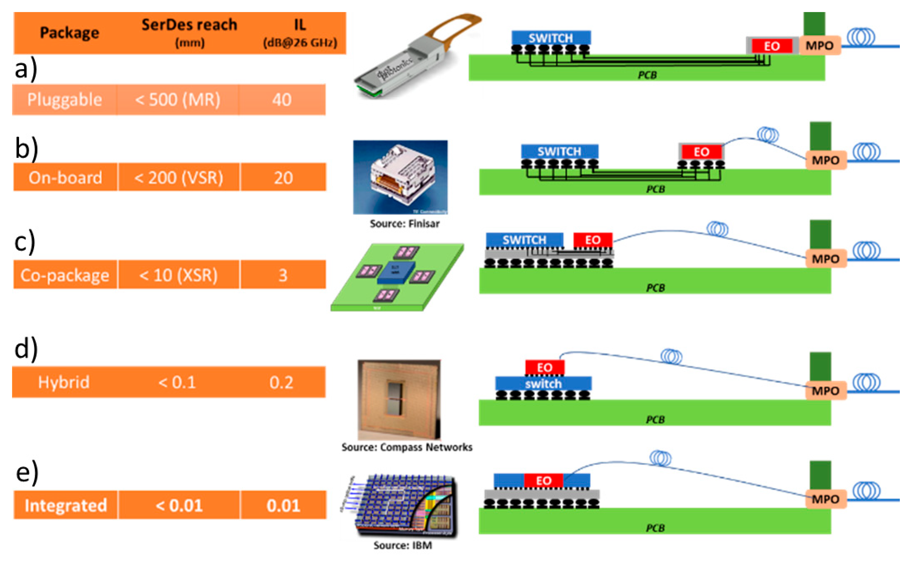
Figure 1. The progress of integrating the optical interconnect with the switch ASIC.
Applsci 11 06098 g001
Figure 2. A schematic of the L3MATRIX Approach: Switch and I/O ASICs co-packaged on a common substrate. Inset: Side-view layout of the chiplet assembly with Tx and Rx SiP matrices; the chiplet is assembled facing down through a cutout hole in the substrate.
Applsci 11 06098 g002
Figure 3. L3MATRIX integration scheme. L3MATRIX is a 2D SiP matrix with (4 × 16) cells, with each cell being optically and electrically isolated from its neighbors. The unit cell is a full SiP transmitter or receiver with an embedded DFB laser. The lasers in each row have a CWDM wavelength, and the output of each column is multiplexed and fiber coupled. The 2D SiP is back illuminating, with a Silicon microlens assembled on the back surface to assist in fiber coupling. The analog chip drives the Mach–Zehnder Interferometer (MZI) modulator and supplies DC bias to the DFB lasers.
Applsci 11 06098 g003
Figure 4. Mask layout of the reticle created in Nazca-Design, including two SiP matrix circuits for 4 wavelength CWDM and WDM, and test structures (top) of various components provided by the L3MATRIX designers. The fabrication was carried out at the AMS foundry; Detailed SEM images of the components are shown in Section 3.
Applsci 11 06098 g004
Figure 5. Transmitter cell layout for WDM and CWDM. The cell footprint is 1000 μm × 1750 μm. GC—Grating Coupler, MZM—Mach–Zehnder Modulator, MMI—Multimode Interference Coupler, w—with, w/o—without. The cell output with multiplexer from 4 cells is waveguided to an echelle grating multiplexer.
Applsci 11 06098 g005
Figure 6. Passive device manufacturing. Schematic representation of the main process steps: (a) SOI wafer as starting material, (b) silicon dioxide hard mask deposition, (c) silicon structuring by time-controlled shallow etching, (d) complete silicon etching in selected areas, (e) silicon dioxide top cladding deposition with Chemical-mechanical polishing (CMP) planarization.
Applsci 11 06098 g006
Figure 7. SEM micrograph of a ridge waveguide. Sidewall roughness is invisible using one detector (left) and visible using another (right).
Applsci 11 06098 g007
Figure 8. (a) Transmission spectra of three waveguides having different lengths (L = 2.8 mm, 8.7 mm and 14.6 mm) for cut-back analysis of the propagation losses. (b) Propagation losses (dB/mm) of rib waveguides extracted with the least mean square method, allowing us to find the best linear regression by minimizing the sum of squared errors. The propagation losses are reduced to 0.15 ± 0.05 dB/mm (mean value) after our developed thermal oxidation process was applied. The error bars on the propagation loss values at each wavelength arise from the goodness of the linear fit with respect to the measured data set. (c,d) Comparison of slow-light waveguide band gap (c) before and (d) after our thermal oxidation process was applied. The slow-light waveguides featured a much deeper band gap after the oxidation, which is another clear sign of the achieved sidewall roughness reduction.
Applsci 11 06098 g008
Figure 9. (a) Waveguide with a vertically modulated DBR and (b) optical micrograph of an Echelle grating. Inset—SEM of vertically modulated DBR in the selected square. (c,d) Waveguide with a lateral DFB grating. Top—layout and bottom—SEM micrographs show that OPC improves the corners of the lateral grid.
Applsci 11 06098 g009
Figure 10. (a,b) Typical optical and SEM micrographs of our directional couplers. (ce) Low sidewall roughness has been achieved in both straight waveguides (d) and bends (c,e).
Applsci 11 06098 g010
Figure 11. Grating coupler fabrication by a two-step silicon etching. (a) The first Si etching. Inset: the hard mask (SiO2) on top of the 70 nm Si patterns. (b) Lithography of the second Si etching. Inset: the photoresist mask for second Si etching. (c) The second Si etching. Inset: two-steps Si structure.
Applsci 11 06098 g011
Figure 12. (a) The experimental testbed developed to interface with the L3MATRIX technology. (be) The experimental channel response of (b) input #1 and (c) input #2 of the 2 × 6 Echelle grating, followed by the response of (d) input #1 and (e) input #2 of the 2 × 4 configurations, respectively. The layout of the Echelle grating is shown in (f), where the diffractive grating is visible on the right side of the free space area. The sharp spikes reduce spurious reflections and so help to minimize the crosstalk. (g,h) Optical micrographs of the L3MATRIX Echelle gratings; inset of (g) shows an SEM image of the region indicated by the green rectangle.
Applsci 11 06098 g012
Figure 13. (a) The vertical current injection scheme for thin III–V layers integrated on silicon. (b) The vertical scheme leads to some recombination of the carriers at the edges of the mesa and insufficient overlap with the optical mode. (c) Lateral current injection scheme. In (d), we show the high-level process flow for realizing the III–V on silicon lasers. The silicon chip with the passive photonic structures is planarized by chemical mechanical polishing. Then, the InP wafer with the gain quantum-well stack is bonded to the silicon wafer. The InP wafer is removed, the III–V gain sections are etched, and finally, the electrical contacts are applied.
Applsci 11 06098 g013
Figure 14. The epitaxial structure of the optimized QD laser stack with a total III–V thickness of 236 nm and room temperature PL. For the InAs QDs layer thickness, ML denotes monolayers.
Applsci 11 06098 g014
Figure 15. (a) A sketch of the silicon E/O modulator embedded in a vertical pn junction. (b) SEM cross-section of the Si modulator after HF wet-etch showing the 2-layer metal stack (M1:Wvias/Ti/TiN/Al/TiN, M2: Wvias/TiN/Al/TiN).
Applsci 11 06098 g015
Figure 16. (a) An optical micrograph of the push-pull modulator and (b) DC characterization results. The extinction ratio is >10 dB across 1270-1350 nm range and NRZ OOK eyes diagrams with (c) 1.6 Vpp, (d) 2.3 Vpp and (e) 3.2 Vpp in a differential driving scheme (the drive voltage applied on each arm).
Applsci 11 06098 g016
Figure 17. Pictures of the tapered fast-to-slow-light transitions defined by three different apodization functions: (a) no fast-to-slow light transition (standard slow light waveguide) and (b) Blackman function. (c,d) optical transmission vs. wavelength (light brown plain line), losses vs. wavelength (red dots). (e,f) Mach–Zehnder Interferometer spectra (blue plain line) from which the group index variations vs. wavelength (exp. data: green dots and fit: dashed black line) are extracted.
Applsci 11 06098 g017
Figure 18. S-parameter simulation of the modulator electrodes.
Applsci 11 06098 g018
Figure 19. Chiplet mimic interposer (A) showing the SiP assembly area in purple and the package assembly area in green. A single interposer cell is shown in (B) with the bumps over the SiP transmit cell. The 100-ohm termination design for the modulator is shown in (C); the resulting silicon is in (D).
Applsci 11 06098 g019
Figure 20. The package design showing the RF routing (left) and the actual substrate front and back sides (right) showing the bump area and the BGA matrix as well as the cutout hole.
Applsci 11 06098 g020
Figure 21. The optical design of the 2-lens relay over a 10° grating coupler through the silicon substrate. The optical ray trace is shown in the upper figure and the fiber coupling efficiency from beam propagation on the right side. The lower image shows the bottom silicon lens array. Additional lenses are added to the 2 × 8 array for mechanical support and process integrity.
Applsci 11 06098 g021
Publisher’s Note: MDPI stays neutral with regard to jurisdictional claims in published maps and institutional affiliations.