1. Introduction
Maraveas [
1] provided a comprehensive review and highlighted inconsistencies in the commonly accepted silo analysis and design methods. The main points that could be added to what was included in Maraveas [
1] are fundamental improvements that were recently identified by Tu and Vimonsatit [
2] and Tu [
3], and the relevance of the method called Equation of Silo Quaking proposed by Tu [
4]. The Equation of Silo Quaking was derived based on scientific principles of physics equilibrium considering a discharging silo as a varying mass dynamic problem. The Equation of Silo quaking differs from Janssen-based methods because the flexibility of the structure, discharge rate and material properties are required in determining the dynamic loads, whereas Janssen-based methods only require the material properties and ignore the effects induced by the flexible structure and discharge rate. As such, this correspondence explains the relevance of the ‘Equation of Silo Quaking’ in the analysis and design of silos, and highlights areas requiring fundamental improvements in the commonly accepted silo analysis and design methods in the journal article published by Maraveas [
1].
According to Tu [
3], while existing methods appear scientifically sound within the problem formulated, such methods require fundamental improvements to follow some established scientific principles and engineering mechanics, such as Conservation of Energy, Conservation of Momentum, Newton’s laws of motion, Hooke’s law, Young’s modulus of elasticity, Vibration, and Fatigue. To fully understand the scientific principles cited [
3], it is necessary to systematically evaluate and consider the conditions of the silo prior to discharge to understand how such laws of applied physics and fundamentals of engineering apply to the phenomena observed during discharge:
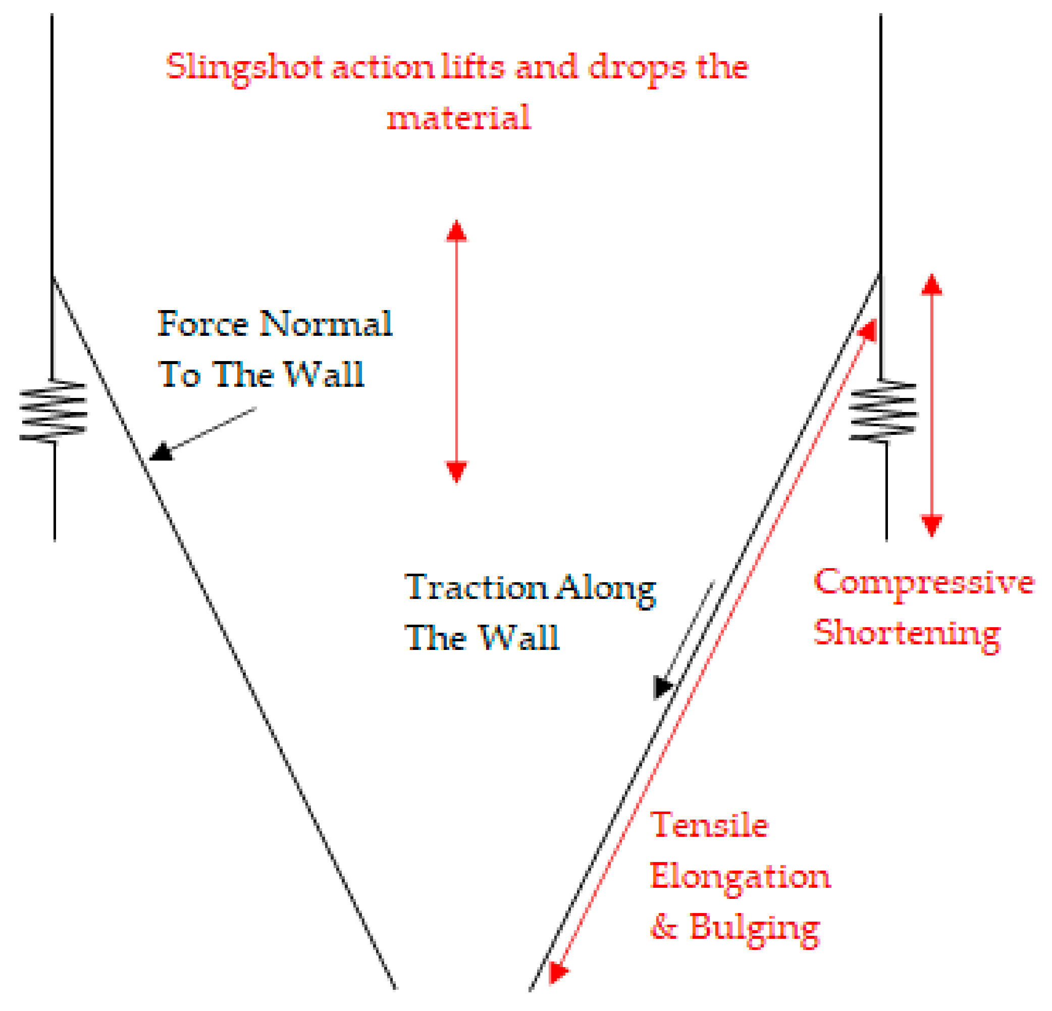
The silo is loaded with the material before discharge. The load due to the material causes the silo to deform elastically—bulging of the container, elongation of the container, and shortening of the columns (
Figure 1). Conservation of Energy suggests that the potential energy is stored in the elastic deformations in the silo structure;
When the gate is opened to discharge the material inside the silo, the forces that cause the initial elastic deformations are lost. The sudden loss of such forces causes the elastic deformations to spring back to their unloaded positions (Hooke’s law); therefore, the potential energy is converted to kinetic energy (Conservation of Energy);
As suggested by the Conservation of Energy, the potential energy (elastic deformations) is equal to the kinetic energy (motions of the silo structure). As such, the rate of loss of the forces that caused the elastic deformations prior to discharge is compensated by the rate of development of the spring-back forces (Newton’s laws of motion). There are many examples of this phenomenon, for example, a simple spring-mass system. When the rate of loss in mass is insignificant, it can be observed that the spring returns to its original position slowly compared to a much quicker rate of loss of the mass. One can install strain gauges, accelerometers and other instruments on the silo to validate;
Prior to discharge, the silo is initially stretched longitudinally, radially, and the columns are shortened, causing it to behave like a slingshot (
Figure 1). Upon the release of the loads that cause the elastic deformations, the stored material is lifted and dropped.
The impact forces caused by the stored material being lifted and dropped can cause buckling in the short term and induce accelerations that cause fluctuating pressures as per Newton’s laws of motion for the entire duration of the discharge cycle;
The amplitudes of the motion are dependent on the dynamic structural properties of the silo and its supporting structure such as mass, damping and stiffness; and
The fluctuating pressures will cause the entire silo to vibrate. Strong vibrations can result in fatigue failures in the long term.
The established scientific principles explained above suggest that during discharge, the fluctuating pressures inside the silo are dependent on the motions of the structure, discharge rate and material properties. Therefore, to achieve equilibrium, the forces during discharge need to be determined from the conditions of the silo prior to discharge, the rate of change of the mass, the properties of the materials inside the silo and the dynamic properties of the overall silo structure. This assertion is backed by the scientific principles presented and by numerous experimental data [
4].
The pressures during discharge cannot be static and are certainly not independent of the motions of the structure in the way suggested in silo analysis and design methods (ACI313-97/313R-97, 1997; AS3774, 1996; ASABE, 1998; ANSI/ASAE EP433 DEC1988 (R2011); EN1991-4, 2006, GB50077 2003) developed from Janssen’s theory. All experiments designed to measure the pressures exerted by the flowing material report fluctuating pressures. In fact, a simple investigation can be carried out by placing the hand on the wall of a discharging silo to feel the vibrations. Some authors [
5,
6,
7,
8,
9] report pressures versus time at a location along the silo wall. Others report average or maximum pressure at the location along the wall [
10,
11,
12,
13]. The methods presented in the international silo design codes are formulated based on maximum pressures measured from experiments at a particular location along the wall of the silo assuming structural properties and discharge rate have no influence on the generated pressure. As an example, a filled silo is discharged until it is half full; the stresses on the silo structure change from the silo being full to half full over time may cause fatigue failure if the silo is discharged often enough.
With the aforementioned distinctions established, areas requiring fundamental improvements in the commonly accepted silo methods found in the silo analysis and design codes and literature are:
Correlation between the pressures developed during discharge with the elastic deformations of the overall silo prior to discharge, the motions of the overall silo, dynamic structural properties of the overall silo, the flow rate and the spring back force due to the overall silo being lighter need to be included in the analysis and design methods; and
Fatigue design needs to be considered to ensure the silo and its supporting structure are structurally adequate for their intended use.
Based on these established scientific principles, the formulations presented in the international silo design codes are technically correct only if the silo supporting structure is sufficiently rigid, the wall is sufficiently rigid, the discharge rate is sufficiently low and the frequency of discharge during the design life of the silo is sufficiently low not to cause fatigue, related structural failures and related occupational health and safety issues. It should be noted that most peer reviewed scientific publications on this topic differ from the method proposed by Tu [
4], because the effects induced by the flexible silo structure and discharge rate have not been adequately incorporated.
The established scientific principles require the forces generated during discharge to be calculated from the material properties of the granules, structural properties of the silo and discharge rate. Additionally, a number of established scientific principles from different scientific fields have been incorporated in the Equation of Silo Quaking to ensure there is equilibrium between the granules inside the silo, the silo structure and surrounding air. It must be noted that the method explained in this correspondence enables the engineer to reduce the forces generated during discharge by altering the material properties, structural properties and discharge rates enabling the silo to be more economical and safer. It is important to consider that altering material properties and discharge rates may not be practical in industrial settings without impacting on the production throughput compared to altering structural properties. In this correspondence, the established scientific principles used in the Equation of Silo Quaking and how it is applied in the context of silo analysis and design will be explained.
2. Theoretical Background
Tu [
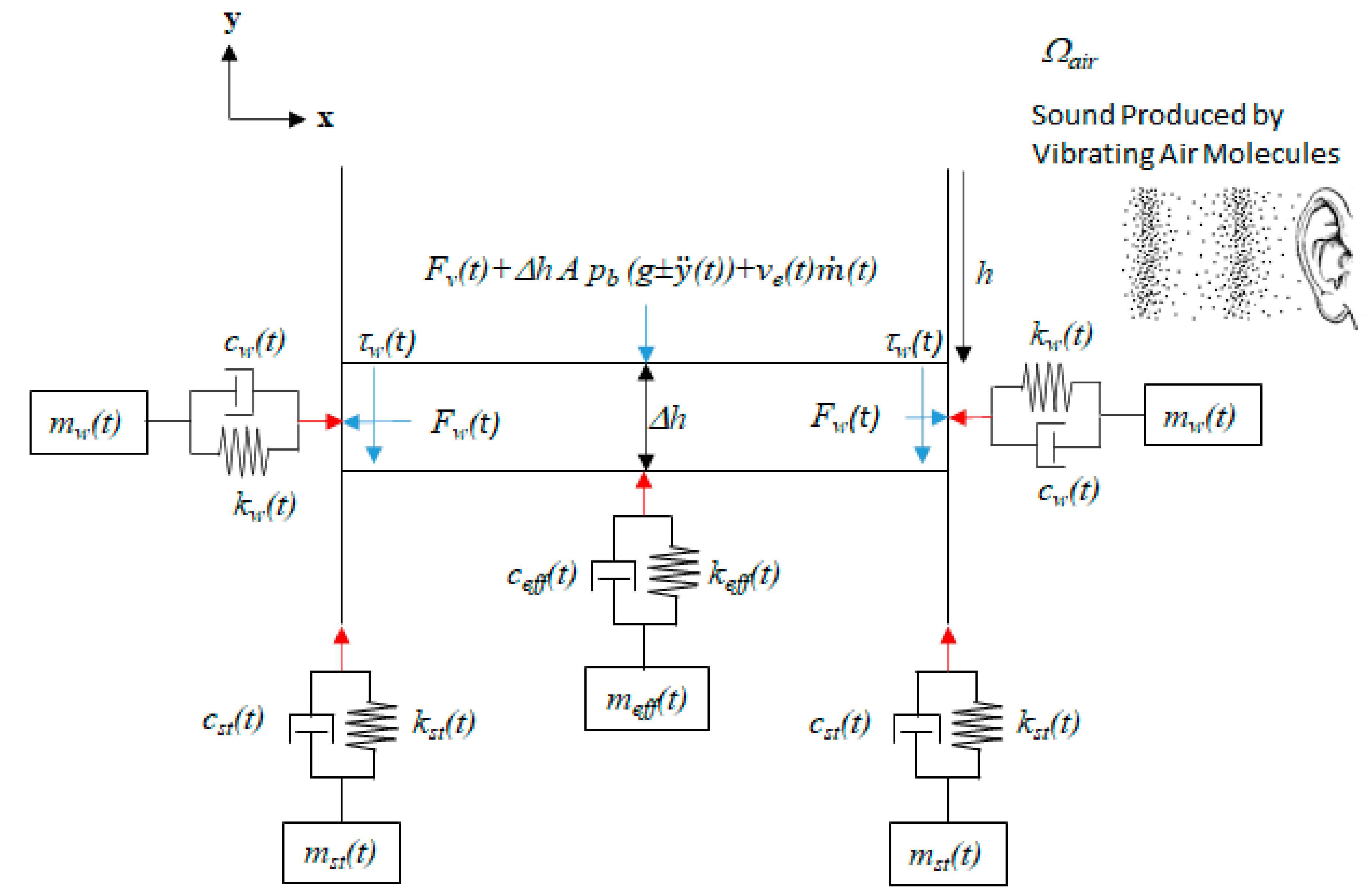
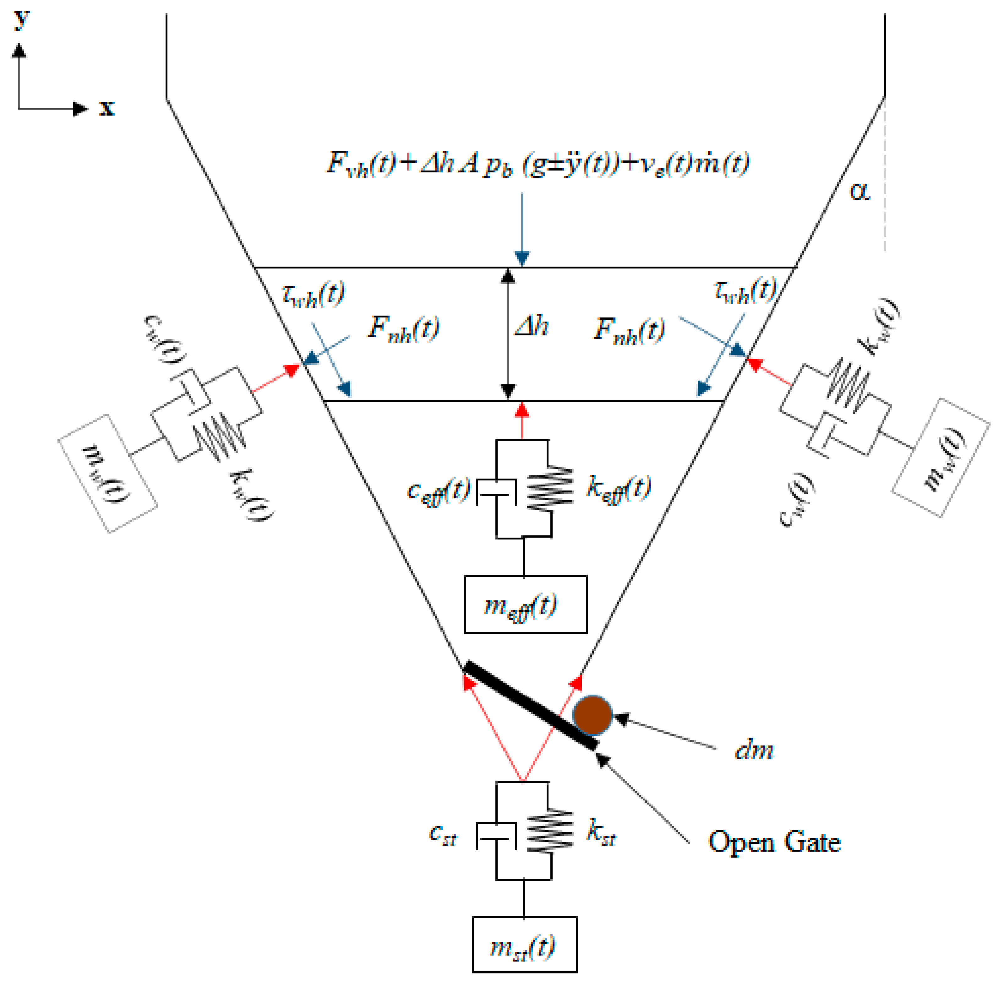
4] formulated the theory, which is graphically illustrated in
Figure 2 and
Figure 3 and mathematically summarised in Equation (1). to describe the phenomena observed during silo discharge.
Figure 2 and
Figure 3 and Equation (1) illustrate a state of equilibrium between the granular material inside the silo, the silo structure and surrounding air. Although Equation (1). illustrates the equilibrium of the entire problem in a single degree of freedom, it must be understood that Equation (1). is an extension of the traditional equation of motion, which can be expanded to many degrees of freedom to capture and incorporate relevant physics. The theory incorporated a number of established scientific principles to illustrate equilibrium between the granules inside the silo, the silo wall and supporting structure, and the surrounding air for the entire duration of the discharge cycle—the commonly accepted silo theories lack such equilibrium and physics. Additionally, to adequately incorporate the relevant physics and simulate the phenomena discussed earlier, Equation (1). needs to be solved for the entire duration of the discharge cycle, taking into consideration the initial elastic deformations, forces applied, material properties, discharge rate, change in the total mass of the structure and properties of the silo structure as a whole to maintain equilibriums between the granules, the structure and surrounding air.
where
is the acceleration at time
t,
is the velocity at time
t,
is the displacement at time
t,
t is the time,
is the total mass of the silo system including the materials inside the silo at time
t,
is the critical damping ratio at time
t,
is the stiffness of the system at time
t,
dm is the mass loss at time
t, and
is the resultant dynamic force generated by the flowing granules and mass loss at time
t. The variables
dm and
need to be determined from the material properties and net accelerations of the silo structure as a whole.
3. Solution Procedure
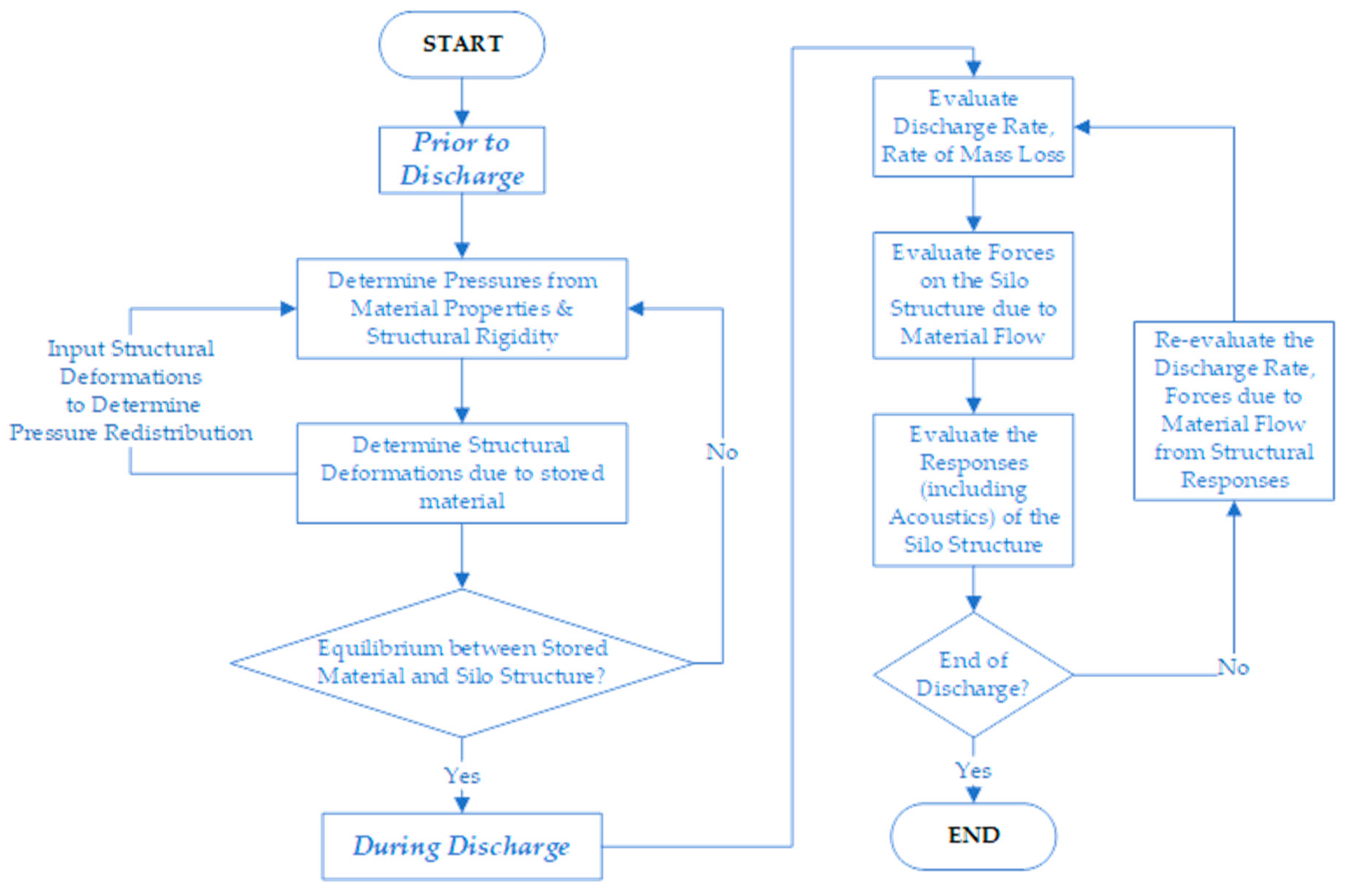
The procedure for evaluating
Figure 2 and
Figure 3 and Equation (1) is graphically illustrated in
Figure 4. Prior to discharge, it is required that forces inside the silo are in equilibrium with the flexible silo structure as a whole. During discharge—the discharge rate, forces due to flowing granular particles, responses of the overall silo structure due to flowing granular materials and acoustics interactions need to be evaluated. In particular, the discharge rate and pressures due to flowing material need to be evaluated from the overall motions of the structure for the entire duration of the discharge cycle.
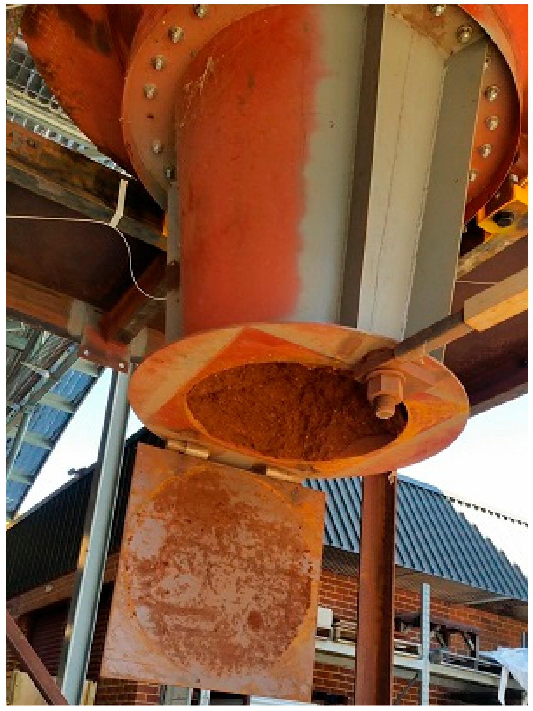
It is commonly accepted in geotechnical engineering and material engineering that each material has certain mechanical properties such as modulus of elasticity, hardness, stiffness, particle shape, particle size, angle of internal friction, angle of repose, plastic limit, liquid limit, moisture content, density, bulk density, void ratio, coefficient of thermal expansion, swell factor, cohesion, adhesion, shear strength, compressive strength, and etc. Under operating conditions, properties such as moisture content, bulk density, particular distribution, particle size and particle shape may not be controllable. Also, some of these material properties may vary between seasons. It is also commonly accepted that a change in the material property can cause the material to behave differently under different loading conditions—evidently, extra moisture absorbed by the material caused flow blockage shown in
Figure 5. Furthermore, it is established that granular material exerts a horizontal force and vertical force along the wall of the silo, and the material properties govern the magnitude of the force exerted by the material on the silo and how the material will flow out of the silo.
3.1. Prior to Discharge
It can be observed in
Figure 5 that prior to discharge, the gate is holding the material and each material layer acts as structural supports for the layer above, as per Janssen’s theory. Therefore, the stiffness of the hopper, its support, the gate and the material determine how much of the total force is distributed to the wall, the gate and the material layers beneath [
6]. The fundamentals of geotechnical engineering suggest that the reaction force generated by the material layers below being in compression. Thus, material compressibility is of importance. The compressibility of the material was recently highlighted by Roberts, Shen, Beh, Chen and Donohue [
14]. It was emphasised that the loads on the gate are governed by the compressibility of the bulk material and the stiffness of the gate in the introduction and conclusion parts of the manuscript. By definition, compressibility is defined as the capability of the soil to decrease its volume under compressive stress [
15,
16]. According to principles of soil mechanics, the compressibility of granular material is influenced by its void ratio [
17], moisture content [
17], relative density [
18], particle distribution [
18], particle size and shape [
19,
20], mineralogy [
19], effective stress acting on the material [
17], structural arrangement of the particles [
21], and is often measured by the oedometer or consolidometer or triaxial shear tester [
17,
22,
23]. In the field of geotechnical engineering, compressibility obtained from field or laboratory tests are often used to estimate settlement of foundation and is commonly expressed as soil stiffness (applied pressure vs deflection) which has a unit of kPa/mm or void ratio vs effective stress [
13] depending on the type of analysis.
The physics of the silo and equilibrium of forces before discharged is captured in Equation (1) at time step 0 where the distributions of those forces that cause the elastic deformations of the silo and its supporting structure are determined from the material properties and structural properties. The redistribution of forces due to elastic deformations of the silo mentioned by Brown, Jarrett and Moore [
6] is also incorporated in Equation (1) at time step 0. It is assumed that the velocity and acceleration of the entire silo structure are 0 at time step 0. However, there are situations where the velocity and acceleration of the silo structure are not 0 at time step 0 (prior to discharge) because of an earthquake or heavy machinery operating near the silo. In such situations, the velocity and acceleration of the silo need to be incorporated, and the forces exerted on the silo due to the material inside the silo need to be determined from the net accelerations of the structure to achieve equilibriums of forces as suggested by the established scientific principles and fundamentals of engineering mechanics mentioned earlier.
3.2. During Discharge
At time step 1, when the gate is opened to enable the granular particles to flow out of the silo, the following phenomena can be observed:
The support mechanism and resistant forces provided by the gate are lost;
The material layers spanning across the hopper at the gate level must provide the lost forces supplied by the gate before open to prevent the material from flowing out of the silo;
Assuming that the hopper is not subjected to any external force or acceleration that induces the material to flow, thus the only force causing the material to flow is gravity;
Each particle must overcome the resistant forces surrounding it to flow, and if it cannot overcome the resistant forces, it will adhere to another particle beside it, forming a collection of particles or adhere to the boundary;
The particles will stop flowing if the resistant forces are sufficient to prevent the particles from flowing. This is evident in
Figure 5, where the dome formed by the particles having sufficient strength to prevent the other particles from flowing further, causing a blocked condition. Such dome formation is an active area of research, and some recent contributions include Lee, Wu, Chen and Chiang [
24] and Khezri, Mohamad, HajiHassani and Fatahi [
25]. The hopper shown in
Figure 5 was designed in accordance with relevant granular theories to prevent blockage. However, the blockage suggests that such theories need fundamental improvements as well;
If all of the particles can overcome the resistant forces and move together, then the flow is considered mass flow [
26,
27]; if some of the particles near the boundary cannot overcome the resistant forces and adhere to the boundary while other particles far away from the boundary flow out of the silo, then the flow is considered funnel flow [
28,
29]. Intermediate or transition flow happens when the forces causing the material to flow near the boundary fluctuate between being higher and lower than the forces resisting the flow, thus causing intermittent material to build up inside the silo [
30,
31]. Therefore, whether the flow is mass, funnel or intermediate is dependent on forces inducing flow and the ability of the particles to overcome the resistant forces, such as cohesion, adhesion, friction and interlocking forces, which exist to prevent the particles from flowing whether individually or lumped together; and
If gravity alone is insufficient to enable flow, then other forces such as external accelerations can be introduced to enable the particles to flow [
32,
33,
34,
35,
36]. This phenomenon can be readily observed in a saltshaker, where the salt particles do not flow out of the saltshaker readily without the user shaking it because outlets are small; thus, the resistant forces are significantly higher than the gravity force that causes the particles to flow. However, to get more salt particles from the saltshaker, the user needs to shake it. Therefore, the flow rates need to be determined from the overall motions of the structure and the material properties, as suggested by Equation (1)
Additionally, at time step 1, as the particles start flowing out of the silo, the forces that caused the initial deformations in the structure are lost, causing the elastically stretched silo to spring back to its unstretched positions. This phenomenon is coupled with the sudden loss of the total mass of the structure, which causes the elastically shortened supporting structure to spring back. The spring back motions convert the potential energy to kinetic energy, compress and lift the materials inside the silo then drop the granular particles inside the silo. In addition to the spring back force, the law of physics Conservation of Momentum suggests that the mass loss generates a dynamic force in the opposite direction, satisfying Newton’s laws of motion. Conservation of Momentum [
37,
38] is one of the governing laws of physics that explains how rockets propel forward [
39]. Another source generating dynamic load is the granular particles hitting the silo wall [
40,
41,
42,
43,
44,
45]. Such phenomena can generate significant dynamic forces that have the potential to buckle the silo, buckle its supporting structure, and cause fatigue failure in the long term. In essence, the rate of development of the dynamic forces is equal to the rate of loss of the total mass of the silo and the discharge rate as suggested by the established scientific principles and fundamentals of engineering mechanics.
The distinction worth noting is the change in the total mass of the structure, which changes the properties of the structure, as presented in Equation (1). Additionally, the established scientific principles, fundamentals of engineering mechanics and numerous experimental data suggest that the granules inside the silo are subjected to accelerations, commonly referred to as g-force, induced by the moving silo structure whether globally or locally [
2]. Since the granular particles inside the silo are unrestrained, the induced accelerations can cause many phenomena such as rarefaction waves travelling up the material column, compression waves, directional changes to the material’s shearing direction, packing density changes, volumetric changes, unsymmetrical lateral pressures, dilation, fluctuating flow rates, periodic shock waves, periodic formation and collapse of the arches inside the hopper, formation of the natural hopper at approximately mid-height of the cylinder portion of the silo, slip-stick, loud foghorn-like sound at irregular intervals and magnified vertical and lateral pressures [
2,
40,
46,
47,
48,
49,
50,
51,
52], which can drive the response even stronger. Therefore, the equilibrium between the flowing granular material and the silo structure as suggested by the established scientific principles and fundamentals of engineering mechanics needs to be evaluated at each time step [
3].
3.2.1. Granular-Structure Interactions
At each time step, the response of the entire silo structure, the flow of the granular material and most importantly, the interaction between the silo structure as a whole and the flow of the granular must be evaluated similarly to soil-structure interaction analysis commonly used in earthquake engineering. Such assertion is demonstrated mathematically in Equation (1) and diagrammatically in
Figure 2 and
Figure 3. The response of the structure equals the force generated by the flowing granular material and vice versa for the entire duration of the discharge cycle. This type of analysis is similar to soil-structure interaction analysis commonly found in earthquake engineering. However, the distinctions are the g-forces experienced by the soil particles being inside the structure, move rapidly, and damping from the surrounding mass of the earth is not available. In essence, at each time step, the response of the structure is determined from the structural properties such as mass, damping and stiffness; the flow rate is determined from the material properties and net accelerations of the overall silo structure; and the force due to the material flowing is determined from the response of the structure or net accelerations, rate of change of the total mass, flow rate and material properties.
3.2.2. Flow Properties
In relation to flow properties, to date, granular scientists have always considered the silo structure to be infinitely rigid in their research. Although, in developing their theories, such as the discrete element method (DEM) and associated flow properties, granular scientists have taken great care in ensuring their numerical models produce comparable experimental results. However, they assumed infinitely rigid silo and supporting structure, but their experimental or scaled physical models used were not infinitely rigid and were vibrating throughout the experiments as suggested by the scientific principles mentioned earlier. The motions of their experimental physical models were embedded in the data obtained, which were used later to create and validate granular flow theories and properties. From principles of structural dynamics, the motions of the silo structure are governed by the properties of the structure; thus, a change in the stiffness, damping or mass of the structure can produce different results. Therefore, according to Equation (1), the validity of these flow properties created based on the assumption that the silo structure is infinitely rigid need to be investigated to be used in Equation (1).
3.2.3. Structural Dynamics and Acoustics
From the fundamentals of vibro-acoustics, a specialist field of structural dynamics and acoustics, the vibrating structure can cause a loud sound to be heard from a distance away if the frequency of vibration is within the human audible spectrum (20 to 20,000 Hz) [
53] and the amplitude is sufficiently high [
54]. Similarly, the fundamentals of wind engineering suggest that air disturbance can cause the structure to vibrate [
55]. Therefore, such physics and engineering fundamentals are required to analyse the condition during silo discharge where a loud sound can be heard. The established scientific principles and fundamentals of engineering mechanics suggest that the loud sound is caused by the vibrating silo wall, which in turn causes air disturbance at frequencies audible to human and with sufficient in amplitude. Although, on rare occasions, the air disturbance can come from other sources, such as the flow of air into the silo from ventilation tubes which can cause strong motions and loud sound. The equilibrium between the air particles and the vibrating silo wall for the entire duration of the discharge cycle is expressed in Equation (1).
It has been demonstrated theoretically in Equation (1) and experimentally that the silo will vibrate during discharge [
4,
56,
57]. The amplitude and frequency of vibration are dependent on the driving force caused by the flowing granular particles, mass, damping and stiffness of the overall silo structure. As such, it is important to analyse the frequencies of the overall silo and the flow to avoid resonance, as argued by others. In structural dynamics, natural frequencies would generally be required when solving the traditional equation of motion in the frequency domain [
58,
59,
60]. Equation (1) inherits all the properties of the traditional equation of motion, traditional rocket equation and is required to be solved in the time domain incrementally to ensure there is equilibrium between the silo structure, flowing granular material and the surrounding air. As such, the conditions causing resonance are already captured and resolved when solving Equation (1) incrementally in the time domain, similar to solving the traditional equation of motion in full transient dynamics analysis. The frequency analysis is more applicable in the context of conditional monitoring [
61,
62,
63] of silo’s structural integrity, which will be discussed later in this correspondence.
4. Applications of Equation (1)
Equation (1) can be applied to designing new silos, repair existing silos and conditional monitoring of existing silos, similar to how the traditional equation of motion can be applied to designing new structures, repair existing structures and conditional monitoring existing structures. It is important to note, the established scientific principles, fundamental of engineering mechanics and experimental data suggest that the structural response and the dynamic force generated by the flowing granular material are interrelated and cannot be determined independently—mathematically shown in Equation (1) and graphically illustrated in
Figure 2 and
Figure 3. As such, in designing a new silo or repairing an existing silo, the parameters such as the material properties, structural properties, acoustic properties, supporting ground properties, external accelerations induced by nearby equipment, flow rates, and rate of change of the total mass of the silo need to be evaluated to ensure there is equilibrium between the granular material, silo structure and surrounding air for the entire duration of the discharge cycle. Since the granules are subjected to ‘g-forces’, such equilibrium is critical in ensuring the silo is structurally safe, because it enables the engineer to alter the mass, damping and stiffness of the silo structure; and material properties such as particle size and moisture content to minimise the generated dynamic force.
Since dynamic forces generated during discharge are unavoidable, dependent on the motions of the structure, and the motions of the structure are dependent on the properties of the silo structure—to ensure that the silo is structurally safe for the entire duration of its design life, the silo needs to be designed for fatigue with consideration given to time-dependent structural degradations such as corrosion. As such, site specific operational parameters such as frequency of use, duration of each discharge cycle, environmental conditions, structural deteriorations, induced accelerations from moving vehicles and operating equipment nearby, material properties and all the variations in those parameters need to be considered for the entire design life of the silo. In particular, structural deteriorations cause changes to the properties of the silo structure, such as stiffness, damping and mass, thus will lead to redistributions and amplifications of dynamic loads, as suggested by Equation (1), which may adversely affect the integrity of the silo.
Similar to the traditional equation of motion, which is widely used in the context of structural health monitoring, Equation (1) is also applicable in the context of structural health monitoring to address the time varying nature and interdependency of the dynamic loads, properties of the structure, properties of the materials and other influencing factors, such as environmental factors, site specific operational parameters and induced accelerations from plants operating nearby which cause complex stresses and fatigue failure modes. This is achieved by mounting an array of sensors in signal communication with a computer to detect the flow rates, the mass inside the silo, displacements of the silo structure and granular materials over a plurality of time. The data captured was analysed with computer software configured to solve Equation (1) and logged. Any anomaly can be automatically reported to the designated personnel for review and maintenance planning. Emergency alerts can be sent to the personnel working near silos to evacuate. The logged data can be used later by emerging technologies such as machine learning and artificial intelligence to better maintain and design silos. Such technology can be retrofitted to existing silos to make them safer and better maintained.
5. Dynamic Response of the Structure Due to Sudden Mass Loss
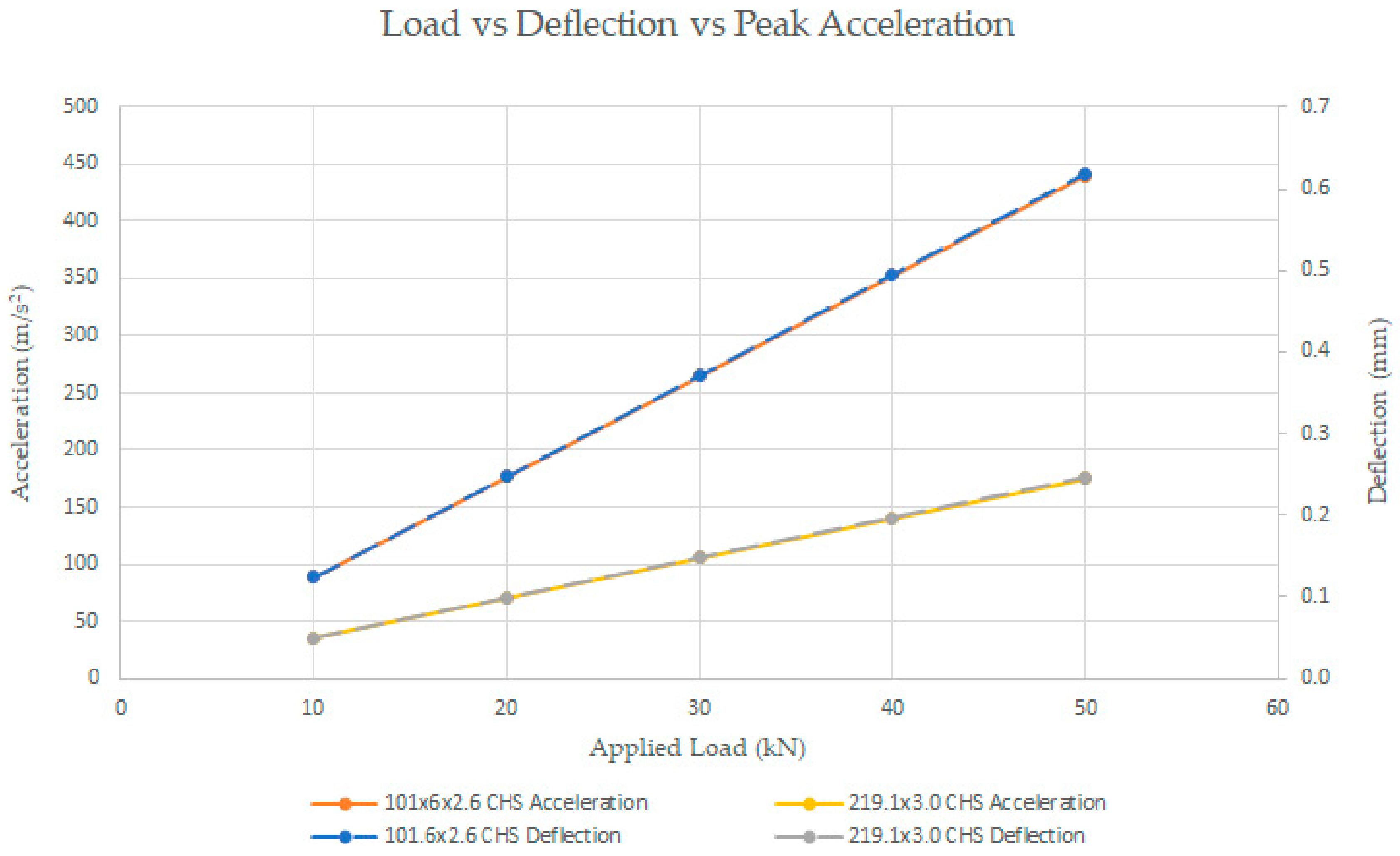
To illustrate the response of the structure due to time varying mass, let us consider the 2 m high circular hollow columns of cross sections illustrated in
Table 1 and fixed at the base. Each column is initially compressed by a point load, which is a large mass, applied at the top of the column, and the point load is removed from the top of the column instantaneously. For simplicity, structural damping is neglected, and the load is assumed to be removed from the structure instantaneously. In reality, sometimes, it may not be possible and practical to remove the large load from the structure instantaneously. As illustrated in
Table 1 the point load was varied in increments of 10 kN, the initial deflection was determined using linear static analysis in Strand7, and the peak acceleration was analysed using linear transient dynamics solver in Strand7, with static deflection set as initial condition and with the load removed instantaneously. The resultant deflections and accelerations due to the application and removal of the loads, respectively, are graphically illustrated in
Figure 6.
It can be seen in
Figure 6. that the structural properties, initial deflection and how quickly the load applied is released are important in determining the resultant accelerations. Fatigue failure may be a concern should the accelerations due to the sudden release of the applied load happen frequently. In the context of silo analysis, such accelerations can cause various observed phenomena such as rarefaction waves travelling up the material column, compression waves, directional changes to the material’s shearing direction, packing density changes, volumetric changes, unsymmetrical lateral pressures, dilation, fluctuating flow rates, periodic shock waves, periodic formation and collapse of the arches inside the hopper, formation of the natural hopper at approximately mid-height of the cylinder portion of the silo, slip-stick, loud foghorn-like sound at irregular intervals and magnified vertical and lateral pressures [
2,
40,
46,
47,
48,
49,
50,
51,
52].
6. Conclusions
In summary, silo theories developed from Janssen’s theory assume that the silo and its supporting structure are infinitely rigid, which is not a realistic representation of some silo systems. The assumption that the structure is rigid and does not influence the generated forces leads to a lack of equilibrium between the granules inside the silo, the silo structure and the surrounding air for the entire duration of the discharge cycle. Such methods suggest that the elastic deformations of the overall silo structure prior to discharge and discharge rate have no influence on the generated dynamic forces at the start of the discharge cycle when the gate is opened. If such physics were valid, then the arrow would fly just as far and fast irrespective of how far the archer stretched the cable and how quick the grip on the arrow was released.
The alternate method explained in this correspondence incorporates many established scientific principles from many engineering and science disciplines to establish equilibrium between the silo structure, granular material and surrounding air for the entire duration of the discharge cycle. Such equilibrium is not present in the silo theories developed from Janssen’s theory. The alternate method requires the silo loads during discharge to be determined from the conditions of the silo prior to discharge, the rate of change of the total mass, the properties of the materials inside the silo, the dynamic properties of the overall silo structure and, in some instances, the surrounding air. Additionally, the equilibrium of forces needs to be determined at each time step and for the entire duration of the discharge cycle. With equilibrium maintained for the entire duration of the discharge cycle, the dynamic forces can be systematically reduced by altering the governing parameters discussed, thus enabling the silo to be safer and more economical to own and operate.
7. Patents
Applications the technology suggested by Equation (1) in the context of silo analysis and design have been patented (PCT/AU2018/050811) in various jurisdictions, as such, permission is required to create or use such applications in the context of silo analysis and design.
Author Contributions
Conceptualization, P.T.; methodology, P.T.; software, P.T.; validation, V.V.; formal analysis, P.T.; investigation, P.T.; resources, P.T.; data curation, P.T.; writing—original draft preparation, P.T.; writing—review and editing, V.V.; visualization, V.V.; supervision, V.V.; project administration, P.T.; funding acquisition, P.T. All authors have read and agreed to the published version of the manuscript.
Funding
This research received no external funding.
Institutional Review Board Statement
Not applicable.
Informed Consent Statement
Not applicable.
Data Availability Statement
Not applicable.
Acknowledgments
The authors would like to acknowledge the staff, editors and reviewers at MDPI for providing suggestions and comments to improve this article.
Conflicts of Interest
The first author owns patents relating to the technology published in PCT/AU2018/050811 in various jurisdictions.
References
- Maraveas, C. Concrete Silos: Failures, Design Issues and Repair/Strengthening Methods. Appl. Sci. 2020, 10, 3938. [Google Scholar] [CrossRef]
- Tu, P.; Vimonsatit, V. Significance of structural vibrations on the flow rates and pressures inside a silo during discharge. Int. J. Lifecycle Perform. Eng. 2019, 3, 360–378. [Google Scholar] [CrossRef]
- Tu, P. Comments on ‘A theory for pressures in cylindrical silos under concentric mixed flow’ (Chem. Eng. Sci., Vol. 223, 115748). Chem. Eng. Sci. 2021, 229, 116070. [Google Scholar] [CrossRef]
- Tu, P. Dynamic Response of Silo Supporting Structure under Pulsating Loads. Ph.D. Thesis, Curtin University, Perth, Australia, November 2018. [Google Scholar]
- Bennett, R.M.; Kmita, J. Static and Dynamic Silo Loads: Experimental Data Comparisons. In Proceedings of the National Conference on Bulk Materials Handling, Melbourne, Australia, 30 September 1996; Institution of Engineers Australia: Barton, Australia, 1996. [Google Scholar]
- Brown, C.J.; Jarrett, N.D.; Moore, D.B. Pressures in a Square Planform Silo during Discharge. Proc. Inst. Mech. Eng. Part E J. Process. Mech. Eng. SAGE J. 1996, 210, 101–108. [Google Scholar] [CrossRef]
- Ramírez, A.; Nielsen, J.; Ayuga, F. Pressure measurements in steel silos with eccentric hoppers. Powder Technol. 2010, 201, 7–20. [Google Scholar] [CrossRef]
- Wang, P.; Zhu, L.; Zhu, X. Flow pattern and normal pressure distribution in flat bottom silo discharged using wall outlet. Powder Technol. 2016, 295, 104–114. [Google Scholar] [CrossRef]
- Chou, C.; Chuang, Y.; Smid, J.; Hsiau, S.; Kuo, J. Flow patterns and stresses on the wall in a moving granular bed with eccentric discharge. Adv. Powder Technol. 2002, 13, 1–23. [Google Scholar] [CrossRef][Green Version]
- Sadowski, A.J.; Michael Rotter, J.; Nielsen, J. A theory for pressures in cylindrical silos under concentric mixed flow. Chem. Eng. Sci. 2020, 223, 115748. [Google Scholar] [CrossRef]
- Wojcik, M.; Enstad, G.G.; Jecmenica, M. Numerical Calculations of Wall Pressures and Stresses in Steel Cylindrical Silos with Concentric and Eccentric Hoppers. Part. Sci. Technol. 2003, 21, 247–258. [Google Scholar] [CrossRef]
- Ooi, J.Y.; She, K.M. Finite element analysis of wall pressure in imperfect silos. Int. J. Solids Struct. 1997, 34, 2061–2072. [Google Scholar] [CrossRef]
- Ooi, J.; Rotter, J.M. Wall pressures in squat steel silos from simple finite element analysis. Comput. Struct. 1990, 37, 361–374. [Google Scholar] [CrossRef]
- Roberts, A.; Shen, J.; Beh, B.; Chen, B.; Donohue, T. Study of gate loads related to stress states in mass-flow bins during bulk solids filling and settlement. Adv. Powder Technol. 2021, 32, 683–692. [Google Scholar] [CrossRef]
- Black, C.A. Methods of Soil Analysis: Part 1 Physical and Mineralogical Properties, Including Statistics of Measurement and Sampling; American Society of Agronomy, Soil Science Society of America: Madison, WI, USA, 1965. [Google Scholar] [CrossRef]
- Jacob, H.D.; Clarke, G.T. (Eds.) Methods of Soil Analysis. Part 4, Physical Methods; Soil Science Society of America: Madison, WI, USA, 2002. [Google Scholar]
- Sridharan, A.; Gurtug, Y. Compressibility characteristics of soils. Geotech. Geol. Eng. 2005, 23, 615–634. [Google Scholar] [CrossRef]
- Sun, Y.; Xiao, Y.; Hanif, K.F. Compressibility dependence on grain size distribution and relative density in sands. Sci. China Technol. Sci. 2015, 58, 443–448. [Google Scholar] [CrossRef]
- Zhang, X.; Baudet, B.A.; Yao, T. The influence of particle shape and mineralogy on the particle strength, breakage and compressibility. Int. J. Geo-Eng. 2020, 11, 1. [Google Scholar] [CrossRef]
- Lafata, L. Effect of Particle Shape and Size on Compressibility Behavior of Dredged Sediment in a Geotextile Tube Dewatering Application; Syracuse University: Syracuse, NY, USA, 2014. [Google Scholar]
- Venkatramaiah, C. Geotechnical Engineering, 3rd ed.; New Age International Pvt. Ltd.: New Delhi, India, 2006. [Google Scholar]
- Surarak, C.; Likitlersuang, S.; Wanatowski, D.; Balasubramaniam, A.; Oh, E.; Guan, H. Stiffness and strength parameters for hardening soil model of soft and stiff Bangkok clays. Soils Found. 2012, 52, 682–697. [Google Scholar] [CrossRef]
- Janbu, N. Soil compressibility as determined by odometer and triaxial tests. Proc. Europ. Conf. SMFE 1963, 1, 19–25. [Google Scholar]
- Lee, C.; Wu, B.; Chen, H.; Chiang, K. Tunnel stability and arching effects during tunneling in soft clayey soil. Tunn. Undergr. Space Technol. 2006, 21, 119–132. [Google Scholar] [CrossRef]
- Khezri, N.; Mohamad, H.; Hajihassani, M.; Fatahi, B. The stability of shallow circular tunnels in soil considering variations in cohesion with depth. Tunn. Undergr. Space Technol. 2015, 49, 230–240. [Google Scholar] [CrossRef]
- Drescher, A. On the criteria for mass flow in hoppers. Powder Technol. 1992, 73, 251–260. [Google Scholar] [CrossRef]
- Chaib, O.; Achouri, I.E.; Gosselin, R.; Abatzoglou, N. Gravity mass powder flow through conical hoppers—Part I: A mathematical model predicting the radial velocity profiles of free-flowing granular systems as a function of cohesion and adhesion properties. Can. J. Chem. Eng. 2021. [Google Scholar] [CrossRef]
- Nguyen, T.V.; Brennen, C.E.; Sabersky, R.H. Funnel Flow in Hoppers. J. Appl. Mech. 1980, 47, 729–735. [Google Scholar] [CrossRef]
- Spencer, A.J.M.; Hill, J.M. Non-dilatant double-shearing theory applied to granular funnel-flow in hoppers. J. Eng. Math. 2001, 41, 55–73. [Google Scholar] [CrossRef]
- Wang, S.; Yan, Y.; Ji, S. Transition of granular flow patterns in a conical hopper based on superquadric DEM simulations. Granul. Matter 2020, 22, 1–16. [Google Scholar] [CrossRef]
- Vidyapati, V.; Subramaniam, S. Granular Flow in Silo Discharge: Discrete Element Method Simulations and Model Assessment. Ind. Eng. Chem. Res. 2013, 52, 13171–13182. [Google Scholar] [CrossRef]
- Wassgren, C.R.; Hunt, M.L.; Freese, P.J.; Palamara, J.; Brennen, C.E. Effects of vertical vibration on hopper flows of granular material. Phys. Fluids 2002, 14, 3439–3448. [Google Scholar] [CrossRef]
- Hunt, M.L.; Weathers, R.C.; Lee, A.T.; Brennen, C.E.; Wassgren, C.R. Effects of horizontal vibration on hopper flows of granular materials. Phys. Fluids 1999, 11, 68–75. [Google Scholar] [CrossRef]
- Lozano, C.; Lumay, G.; Zuriguel, I.; Hidalgo, R.C.; Garcimartín, A. Breaking Arches with Vibrations: The Role of Defects. Phys. Rev. Lett. 2012, 109, 068001. [Google Scholar] [CrossRef]
- Guerrero, B.; Lozano, C.; Zuriguel, I.; Garcimartín, A. Dynamics of breaking arches under a constant vibration. EPJ Web Conf. 2017, 140, 3016. [Google Scholar] [CrossRef]
- Nicolas, A.; Garcimartín, Á.; Zuriguel, I. Trap Model for Clogging and Unclogging in Granular Hopper Flows. Phys. Rev. Lett. 2018, 120, 198002. [Google Scholar] [CrossRef]
- Irschik, H.; Holl, H.J. Mechanics of variable-mass systems—Part 1: Balance of mass and linear momentum. Appl. Mech. Rev. 2004, 57, 145–160. [Google Scholar] [CrossRef]
- Wolny, J.; Strzałka, R. Momentum in the Dynamics of Variable-Mass Systems: Classical and Relativistic Case. Acta Phys. Pol. A 2019, 135, 475–479. [Google Scholar] [CrossRef]
- Hall, N. Conservation of Momentum; NASA: Washington, DC, USA, 2021. [Google Scholar]
- Donohue, T.J.; Wensrich, C.M.; Roberts, A.W.; Ilic, D.A.K. Analysis of a Train Loud-Out Bin using combined continuum methods and Discrete Element Modelling. In Proceedings of the 7th International Conference for Conveying and Handling of Particulate Solids—CHoPS 2012, Friedrichshafen, Germany, 10–13 September 2012. [Google Scholar]
- Anand, A.; Curtis, J.S.; Wassgren, C.R.; Hancock, B.C.; Ketterhagen, W.R. Predicting discharge dynamics from a rectangular hopper using the discrete element method (DEM). Chem. Eng. Sci. 2008, 63, 5821–5830. [Google Scholar] [CrossRef]
- Goda, T.J.; Ebert, F. Three-dimensional discrete element simulations in hoppers and silos. Powder Technol. 2005, 158, 58–68. [Google Scholar] [CrossRef]
- Matuttis, H.-G. Understanding the Discrete Element Method: Simulation of Non-Spherical Particles for Granular and Multi-Body Systems; Wiley: Singapore, 2014. [Google Scholar]
- Oldal, I.; Safranyik, F. Extension of silo discharge model based on discrete element method. J. Mech. Sci. Technol. 2015, 29, 3789–3796. [Google Scholar] [CrossRef]
- Remias, M.G. Discrete Dynamic Modelling of Granular Flows in Silos. Master’s Thesis, Curtin University of Technology, Perth, Australia, 1998. [Google Scholar]
- Wensrich, C.M. Numerical modelling of quaking in tall silos. Int. J. Mech. Sci. 2003, 45, 541–551. [Google Scholar] [CrossRef]
- Wensrich, C.M. Analytical and Numerical Modelling of Quaking in Tall Silos. Ph.D. Thesis, University of Newcastle, Newcastle, UK, 2002. [Google Scholar]
- Roberts, A.W.; Wensrich, C.M. Flow dynamics or ‘quaking’ in gravity discharge from silos. Chem. Eng. Sci. 2002, 57, 295–305. [Google Scholar] [CrossRef]
- Donohue, T.J.; Wensrich, C.M.; Roberts, A.W. Experimental and Numerical Investigation into Silo Quaking; Engineers Australia: Barton, Australia, 2016. [Google Scholar]
- Wilde, K.; Rucka, M.; Tejchman, J. Silo music—Mechanism of dynamic flow and structure interaction. Powder Technol. 2008, 186, 113–129. [Google Scholar] [CrossRef]
- Tejchman, J. Dynamic Effects During Silo Flow. In Proceedings of the National Conference on Bulk Materials Handling, Melbourne, Australia, 30 September–2 October 1996. [Google Scholar]
- Tejchman, J. Silo-quake-experiments and a polar hypoplastic model. In Proceedings of the 3rd European Symposium on Storage and Flow of Particulate Solids, Nuremberg, Germany, 21–23 March 1995. [Google Scholar]
- Cutnell, J.D.; Johnson, K.W. Physics, 9th ed.; Wiley: Hoboken, NJ, USA, 2012. [Google Scholar]
- Manik, D.N. (Ed.) Vibro-Acoustics: Fundamentals and Applications; CRC Press: Boca Raton, FL, USA, 2017. [Google Scholar]
- Giaralis, A.; Petrini, F. Wind-Induced Vibration Mitigation in Tall Buildings Using the Tuned Mass-Damper-Inerter. J. Struct. Eng. 2017, 143, 04017127. [Google Scholar] [CrossRef]
- Fletcher, J. An Investigation into How Varying the Moisture Content of Sand Affects Silo Honking during Discharge through a Perspex Tube. Bachelor’s Thesis, Curtin University, Perth, WA, Australia, 25 May 2018. [Google Scholar]
- Griffiths, J. Impact of Moisture Content on the Dynamic Response of a Silo Model Wall during Discharge. Bachelor’s Thesis, Curtin University, Perth, WA, Australia, 29 October 2018. [Google Scholar]
- Shrikhande, M. Finite Element Method and Computational Structural Dynamics, 1st ed.; PHI Learning Private Limited: Delhi, India, 2014. [Google Scholar]
- Hart, G.C.; Wong, K. Structural Dynamics for Structural Engineers; John Wiley & Sons: Hoboken, NJ, USA, 2000. [Google Scholar]
- Paz, M. Structural Dynamics: Theory and Computation, 5th ed.; William, L., Ed.; Springer: Boston, MA, USA, 2004. [Google Scholar]
- Brincker, R.; Ventura, C.E. Introduction to Operational Modal Analysis; Wiley: Hoboken, NJ, USA, 2015. [Google Scholar]
- Karbhari, V.M.; Ansari, F. (Eds.) Structural Health Monitoring of Civil Infrastructure Systems; Woodhead Publishing Limited: Cambridge, UK; CRC Press: Boca Raton, FL, USA, 2009. [Google Scholar]
- Deng, Y.; Li, A. Structural Health Monitoring for Suspension Bridges: Interpretation of Field Measurements; Springer: Singapore, 2019. [Google Scholar]
| Publisher’s Note: MDPI stays neutral with regard to jurisdictional claims in published maps and institutional affiliations. |
© 2021 by the authors. Licensee MDPI, Basel, Switzerland. This article is an open access article distributed under the terms and conditions of the Creative Commons Attribution (CC BY) license (https://creativecommons.org/licenses/by/4.0/).


