Article

Design and Simulation of a Vision-Based Automatic Trout Fish-Processing Robot

by
Hossein Azarmdel
1,2,
Seyed Saeid Mohtasebi
2,*,
Ali Jafary
2,
Hossein Behfar
3 and
Alfredo Rosado Muñoz
1,*
1
Department of Electronics Engineering, University of Valencia, Burjassot, 46100 Valencia, Spain
2
Department of Agricultural Machinery Engineering, Faculty of Agricultural Engineering and Technology, University of Tehran, Karaj 3158777871, Iran
3
Department of Biosystems Engineering, Faculty of Agriculture, University of Tabriz, Tabriz 5166616471, Iran
*
Authors to whom correspondence should be addressed.
Appl. Sci. 2021, 11(12), 5602; https://doi.org/10.3390/app11125602
Submission received: 14 April 2021 / Revised: 8 June 2021 / Accepted: 9 June 2021 / Published: 17 June 2021
(This article belongs to the Special Issue Modelling and Control of Mechatronic and Robotic Systems, Volume II)

Abstract

:

Featured Application

Due to the broad automation in food industry, the need to design and manufacture automate devices with high capabilities in the fish and aquatic processing industries is of great importance. This system is introduced to process trout fish in four steps in an integrated machine including, belly cutting, beheading, gutting, and cleaning processes bsed on the machine vision. The applied grippers stabilize the fish for any trout processing operations. In this system, trout moves inside a canal along the machine, and all the operations are conducted on the fish. Therefore, this system can be applied in the fish supplying markets and fish processing factories, which facilitate the fish cleaning process in different fish sizes.

Abstract

Today, industrial automation is being applied in a wide range of fields. The initial modeling of robots and mechanical systems together with simulation results in optimal systems. In this study, the designed system is simulated to obtain the required velocities, accelerations and torques of the actuating arms in a vision-based automatic system. Due to the slippery skin of fish and the low friction coefficient, it is not easy to design an optimal tool to handle fish. Since the fish-processing operation is undertaken step by step and provides fish stability, it is essential that the gripper enables different processing operations along the system. The proposed system performs belly-cutting, beheading, gutting, and cleaning stages for different fish sizes, based on the extracted dimensions of the vision system. In the head-cutting section, the average speed of the actuator jack was considered as 500 mm s−1. Under these conditions, the maximum required force to provide this speed was 332.45 N. In the belly-cutting subsystem, the required torque for the stepper motor resulted in 1.79–2.15 N m. Finally, the maximum required torque for the gutting stepper motor was calculated as 0.69 N m in the tested processing capacities.

1. Introduction

Trout, with the scientific name of Oncorhynchus mykiss, is from the salmon genus. The recent technology in the food industry is developed in different fields, such as fully automated and intelligent systems based on vision. Since the speed of the processing function, together with the accuracy and quality of the final product, is required, recent systems are equipped with vision-based equipment, especially in the products with different sizes and shapes.
Fish sorting increases the final quality of the product but requires an initial investment and carries with it structural complexities [1]. In small and large fish centers, fish species in high demand are usually available in different sizes. In non-processed fresh fish, some prefer gutted fish; others opt for gutted and beheaded, or just in fillets. It should be noted that trout scales are finer than other species, and it can be processed without scaling.
Due to the broad automation in industry, the need to design and manufacture automated devices with high capabilities in the fish and aquatic processing industries is of great importance. Because of the importance of fish consumption to the food industry, there is a need to design and develop fish-processing systems with higher capabilities than the current models. In fish-processing factories and fish supplying markets, it is necessary to properly stabilize the fish for cleaning operations. Due to the slippery skin and the low friction coefficient, it is usually challenging to control the fish constantly. To increase the system capacity, it is necessary to process the fish with functioning arms while the fish are passing in front of the processing tools.
The initial modeling of the robots and mechanical systems together with simulation results in optimal real systems. In this condition not only are the links and joints and actual movements of the arms and actuators traced, but also the required forces and torques are determined in the most optimized condition. This needs defining the initial conditions of the friction coefficients, the movement limitations, required initial speeds and accelerations. In a study conducted by Beiranvand [2], the minimum length sliding mode control of a three degrees of freedom (DOF) Cartesian parallel robot was modeled and identified considering the virtual flexible links. In another study, kinematic optimal design of a partially compliant four-bar linkage using the elliptic integral solution was applied [3]. An analytical model of a compact flexure mechanism for translational motion together with the designing process was conducted by Hao [4].
A conventional machine vision system (MVS) includes an image-capturing unit (camera), image processing unit, and statistical analysis [5]. Machine vision has been used in the field of aquaculture for classification, sex determination, and quality assessment. This non-destructive method was also applied in fish post-processing steps like removing unwanted parts and cutting the fillet edges. The following are examples of research conducted in this area. To adapt the fish cleaning system to the individual characteristics of each fish, it is necessary to provide special tools for cutting, gutting, cleaning, and gripping fish of different sizes. Machine vision as the main detection and processing tool was applied by Atienza-Vanacloig for tuna growing stages [6]. This method was also applied to develop a fish counting algorithm while passing from the embedded system [7]. It was also applied for fish fillet quality and freshness assessment [8]. Fish freshness can be detected according to the color features of the eyes and the gills [9]. The fish length and size determination algorithm was developed by Miranda [10] and Muñoz-Benavent [11]. In other research, the size, direction, and heterogeneity of the fish were measured based on edge analysis to develop the tools for grading bass species [12].
The mechanical systems and cutting arms are designed in different fish-processing machines. In a design, the researchers developed a head-cutting fish cleaner. In their prototype, the fish was held using two metal plates to separate the fish head in the appropriate position [13]. In order to cut the head, they proposed a mechanism to keep the head in the right position while gripping the body. The designed clamp only allowed the system to cut the head. In this system, the fish was held steady and the head-cutting tool cuts the head by moving toward the fish.
In another system, a machine for fish head cutting was designed [14]. In this machine, the fish were moved using a conveyor chain system with stainless steel semicircular seats. In this model, as the fish passes over the conveyor, the holding arm from the top of the line approaches the moving fish to stabilize it and for beheading processes. Like the previous model, this machine was only able to cut the fish head. The difference between this proposal and the model designed by Buckingham lies in the processing condition of the fish (stable or moving fish) [13]. Due to the high inertia of the cutting tools, it is preferred to process the fish while moving with minimum movement of cutting tools. On the other hand, the capacity of the system is high if the fish moves in front of the cutting arms. Therefore, the system used by De Silva [14] takes priority in terms of meeting the proper dynamic conditions compared to the system designed by Buckingham [13].
Later, Lang [15] proposed a device for cutting salmon heads. In this machine, the fish were placed manually in their seat and then transported to the cutting position by a hydraulic jack. In order to provide linear motion, a rotary motor was used to convert rotational motion to linear motion. This device was also developed to catch the fish for beheading.
Ketels [16] proposed a system for correctly placing the fish in the processing line during head cutting. In this design, they used metal seats mounted on the chains. Since the sorted fish were fed to this system, the fish conveyor seats were designed in fixed sizes. Therefore, in the fish of different sizes, this mechanism cannot be used unless specific conveyor chains are considered for each of the different sizes of the fish.
In another fabricated design, conveyor belts consisting of metal seats were used [17], as applied by Ketels [16]. In addition to the clamp designed for beheading, another clamp was used to separate the fishbone. It should be noted that, although the designed device was able to perform two different operations, two different types of clamp were used for each step of beheading and deboning. In the proposed system in the present study, in addition to the ability to perform various steps of belly cutting, gutting, and beheading, it will be possible to perform all these steps in one integrated system.
Urushibara [18] designed and fabricated a device for fish beheading and gutting without cutting the belly. In this design, the fish were transported while lying on their sides to cut the head and evacuate the belly contents. In another system, a device to grip the fish and clean the belly contents was applied [19]. In this system, contrary to the model proposed by Paulson [20], the fish were transported downward between two support straps along with the device. Similarly, a device to catch the fish for removing blood clots near the spinal cord was used [21]. This tool is only for catching fish to suck the blood and blood clots, and it is a single-use clamp in the fish-processing industry. This clamp was applied in a fish filleting machine.
A flow tool for extracting belly content was designed and fabricated [22]. The designers have offered this tool for cutting fish fillets, but they have also suggested this tool for evacuating the belly content. In this system, as the fish moves towards the cutting tool, the blade contacts the belly content and removes it from the belly cavity. It was necessary to separate the fish head from the body in the previous step.
In a design proposed by Finke [23], a device with attached material to the spinal cord with two sets of rotating disks was applied. The first set of the discs guides and presses the fish, and the other set under the fish performs the cleaning operation from beneath the fish. The second set of the disks were placed opposite with angles. In this design, the fish is pulled from the tail, and the belly is downward. In order to use this tool, it is necessary to clean the belly and remove the head in the previous step. Among the described systems, only in the designs proposed by Paulson [20] and Ryan [19], a combination of mechanical and electronic sensors has been applied to detect the dimensions of the fish, which can be applied to extract the fish size and cutting points. Since in each of these systems, only a single operation of cutting or gutting is undertaken, using these sensors is sufficient for dimension determination.
In Paulson’s design [20], the head of the fish remains on the fish, and only the gutting process with the details of belly-cutting, suction, and belly cleaning steps are undertaken in a single system. Also, in the system designed by Ryan [19], the head of the fish is removed in the previous stage, and subsequently, by passing through the conveyor belt, the gutting process is performed. These sensors are used while cutting and cleaning operations are performed on the belly because the exact head-cutting position requires special methods like machine vision.
Then, an automated line for slaughtering and cutting fish heads using machine vision was designed [24]. To slaughter the fish, the pneumatic jacks were equipped to narrow blades. The general structure of the device used in this study is similar to those applied by Storbeck [25] with the difference that, in addition to all devices applied as mechanical tools, the stunning technology enabled the feeding of alive fish so that they can be processed simultaneously. It was also necessary to identify the fishtail and head sides in order to make an injury on the right side.
In the current system, an automated system is designed for trout beheading, gutting, and cleaning. As this system consists of mechanical, controlling, and machine vision sections, the whole system needs an accurate design and synchronization. The mechanical system was designed in CATIA software (Dassault Systems Corporation) and simulated in Automated Dynamic Analysis of Mechanical Systems (ADAMS) simulation software owned by MSC Software Corporation. The controlling algorithm was developed in Siemens TiaPortal15 software and tested to solve any errors. Extracted data from the machine vision system are sent to the control unit by the Ethernet TCP/IP protocol. Finally, by installing magnetic and inductive sensors, pneumatic cylinders and actuators, and user interface panel, the machine functioning was synchronized and calibrated.
Since the system is supposed to process fish of different dimensions, machine vision can provide a precise cutting point determination. With such system, not only the fish dimension is defined, but also the head cutting, belly-cutting length and gutting points are defined based on the fish fin segmentation. Since the fish dimensions are different, there is a high risk of collision between the arms and the grippers as they pass in front of each functioning station. Therefore, designing a system capable of functioning different cutting and cleaning actions on fish of different sizes in an integrated machine is the main goal of this research. The detailed goals are presented as follows:
  • Designing a trout fish-processing system capable of processing the fish in different dimensions.
  • Developing the system into a machine at which different cleaning steps can be performed in one integrated system (belly-cutting, beheading, gutting, and cleaning processes).
  • Designing a system that is adapted with online data extracted from the online image processing technique.
  • Extracting the required forces, torques, and displacements by simulating the real movements.
  • Finally, fabricating and selecting the proper functioning motors and pneumatic jacks of the system based on the applied tools (mechanical design, machine vision, control algorithms, and simulation).

2. Material and Methods

This system is composed of different units which are combined in an integrated system for trout processing. The machine vision system as the main processing and data acquisition unit is mounted in the initial part of the machine. The mechanical design of the system and final fabrication processes are described in detail in the following.

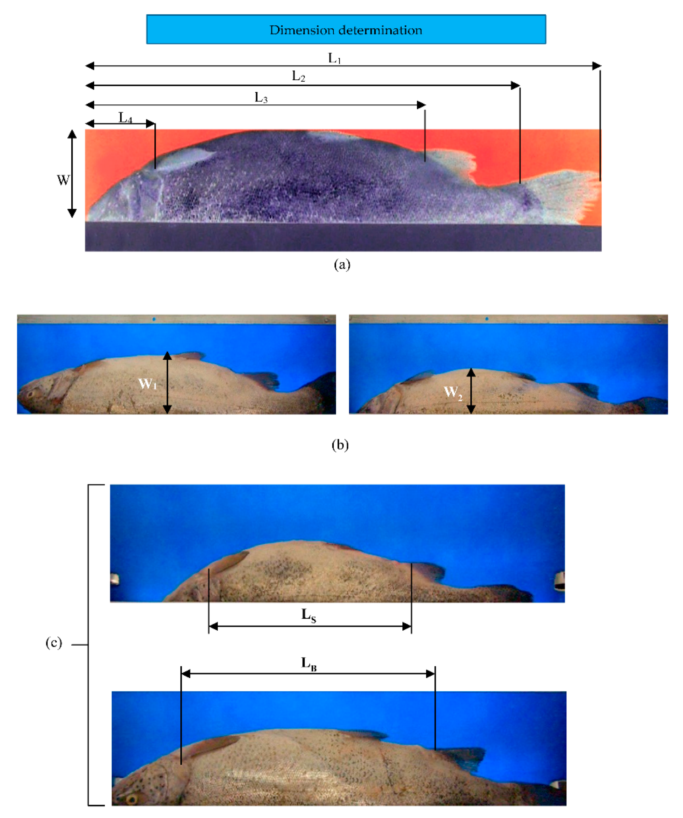
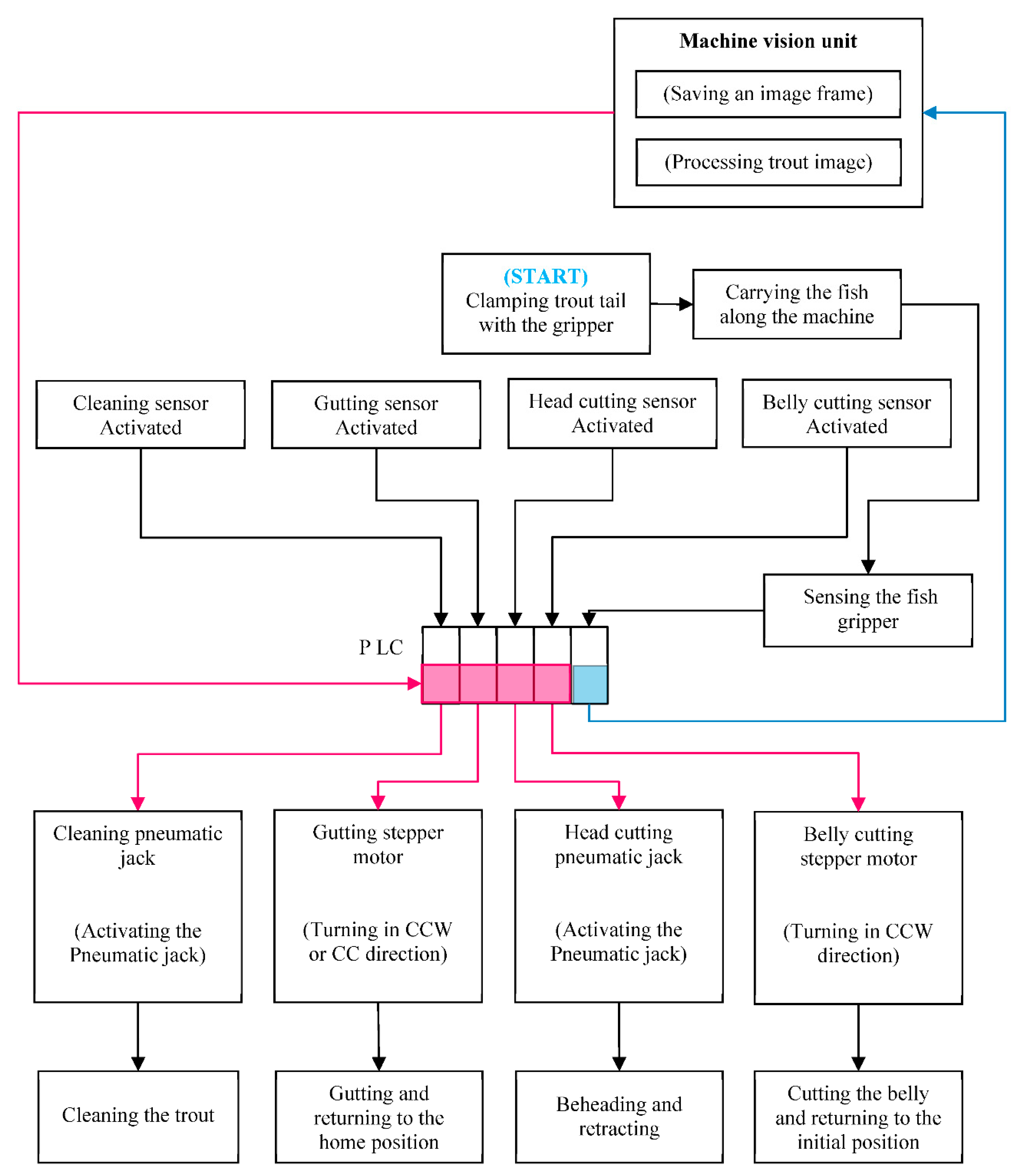
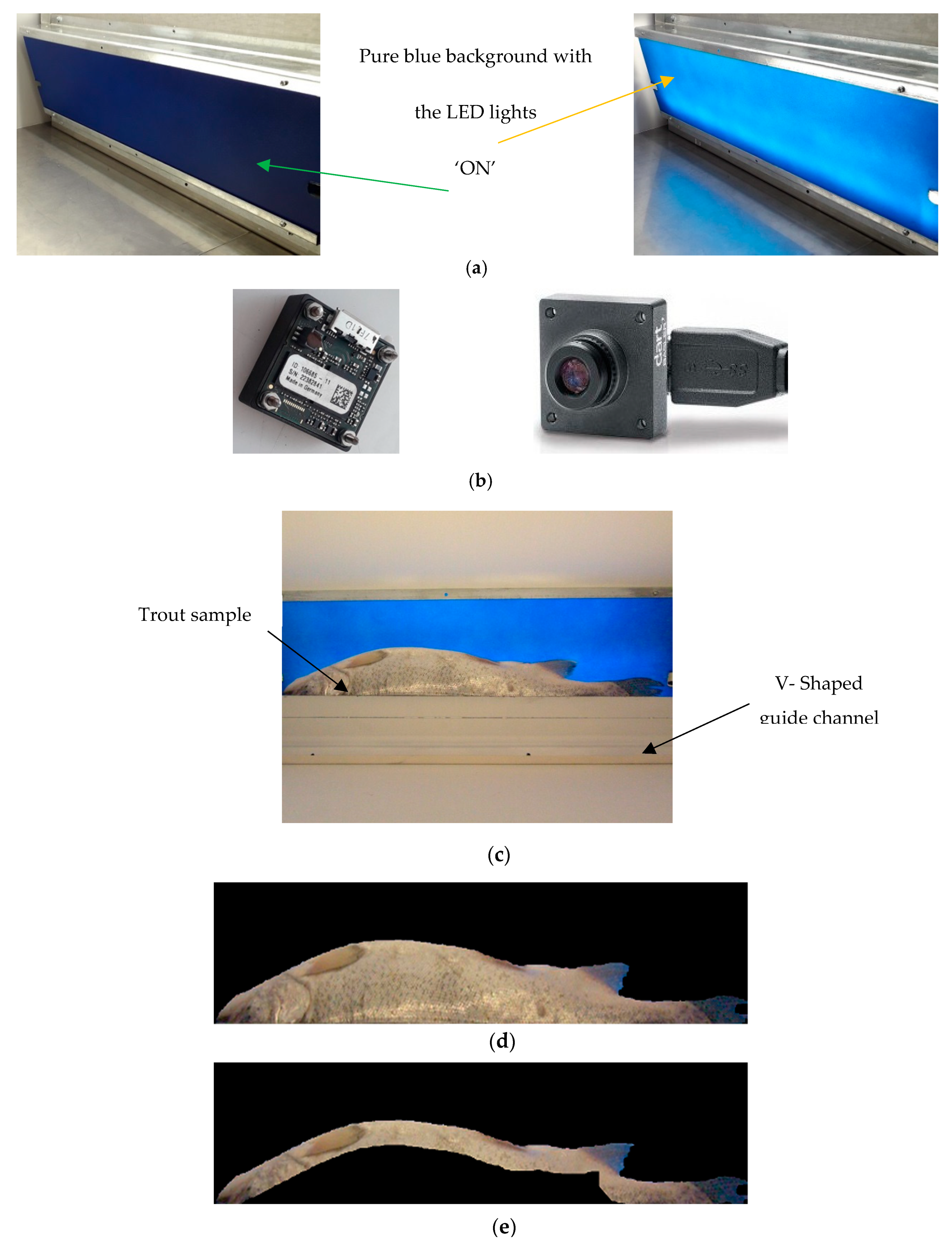
2.1. Machine Vision and Dimension Determination

This system is designed, simulated, and fabricated to process trout in an online condition. The main part of the system is the image processing setup in which the images are captured and the cutting points and dimensions are extracted using the developed algorithm. To develop the cutting point determination algorithm, an imaging case with a light-emitting diode (LED) was designed. We applied a video camera (Basler, daA1280-54uc, USB3) for the online process. To capture the images, as the fish was passing in front of the camera sensor, the signal was sent to the programmable logic controller (PLC) and the frame capturing command was sent to the MATLAB software to store the frame for fish segmentation and dimension extraction. As soon as the dimensions were extracted, they were sent to the controlling unit with the TCP/IP protocol. The machine vision components, segmentation process, and cutting point determination are presented in Figure 1.
The cutting points and extracted dimensions are presented in Figure 2. The head and belly-cutting regions will be considered as the operational points of the system. L1 to L4 are head-cutting point, belly-cutting start point, the body length without tail, and total length, respectively. The operational width of the trout is shown as W.

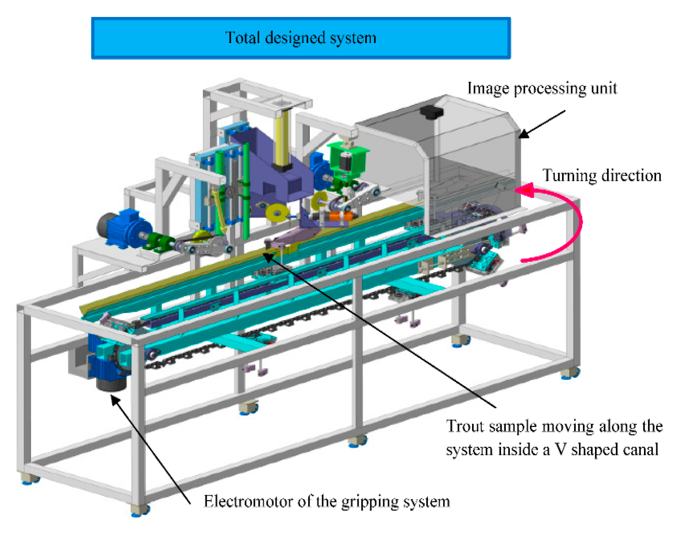
2.2. Designing the Mechanical Parts

In the first step, the initial model was designed by CATIA software. Then, all parts, such as conveyor chain and gears, were defined by entering the exact dimensions of the parts in the software. To enable all fish-processing steps in the system, we considered the dimensions of the chassis: 2.8 m in length, 0.85 m in height, and a width of 0.7 m. The total design rationale is presented in Figure 3.

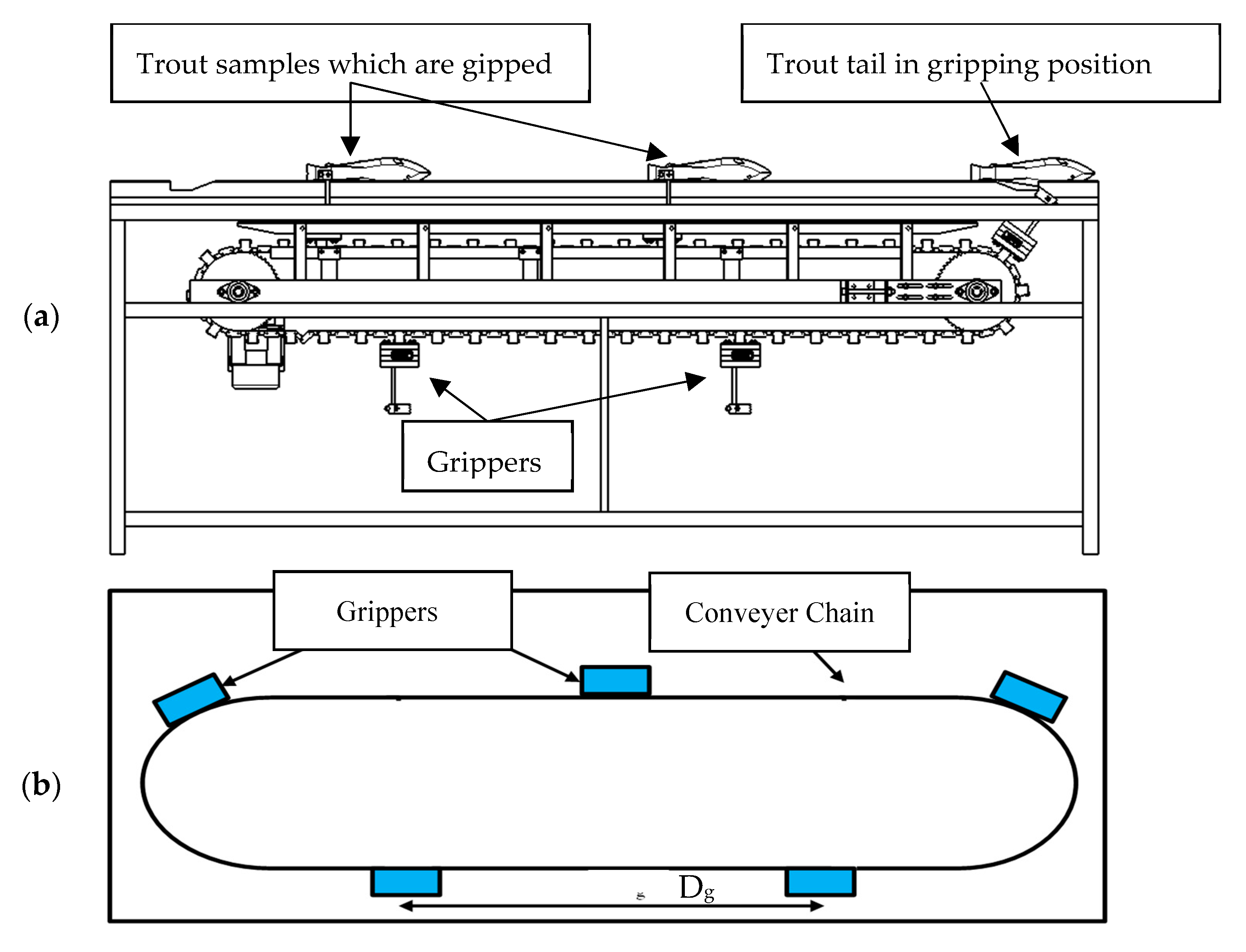
2.2.1. Fish-Carrying Subsystem

One of the most critical points in designing a system with the ability to perform different trout-processing stages is to consider a holding place in the fish body to avoid interfering with cutting and cleaning tools during the various cleaning stages. Therefore, the tail of the fish was selected as the appropriate area.
The fish carrier subsystem consists of four main parts:
  • Fish grippers;
  • Gripper guides and fish canal;
  • Driver AC motor;
  • Gripper conveyer.
In order to stain and increase the wear resistance of steel gears, hard chrome electroplating operation was used. To transmit the motor’s power to the grippers, we selected a stainless steel chain with a length of 4800 mm. By dividing this length into five equal parts, a distance Dg of 960 mm was obtained. Therefore, five grippers were designed, by which five fish are processed in one turn. Figure 4 shows the sketch and schematic view of the conveyor chain and grippers in detail.
This figure shows the gripper position and the conveyor chain with the gripper distance (Dg). If a complete cycle of the conveyor chain is performed for one minute, the number of five fish per minute (MF_5) will be processed by the machine. Under these conditions, the linear velocity of the carrier chain will be calculated using Equation (1):
v = x t
In this equation, ‘v’ is the linear velocity (mm s−1), ‘x’ is the length of the carrier chain (mm), and ‘t’ is one complete path of the chain (60 s). Based on Equation (1), we considered five fish to be processed in one minute; the linear velocity will be calculated 80 mm s−1. Other linear velocity values in different processing capacities are presented in Table 1.
As shown in this table, by increasing the system capacity from four to 10 fish per minute, the linear velocity increased from 53.33 mm s−1 to 133.33 mm s−1. These values are the base inputs for design and simulation of the system. The complete design of the trout-processing system is presented in Figure 5. The subsystems of the machine are described in detail below.

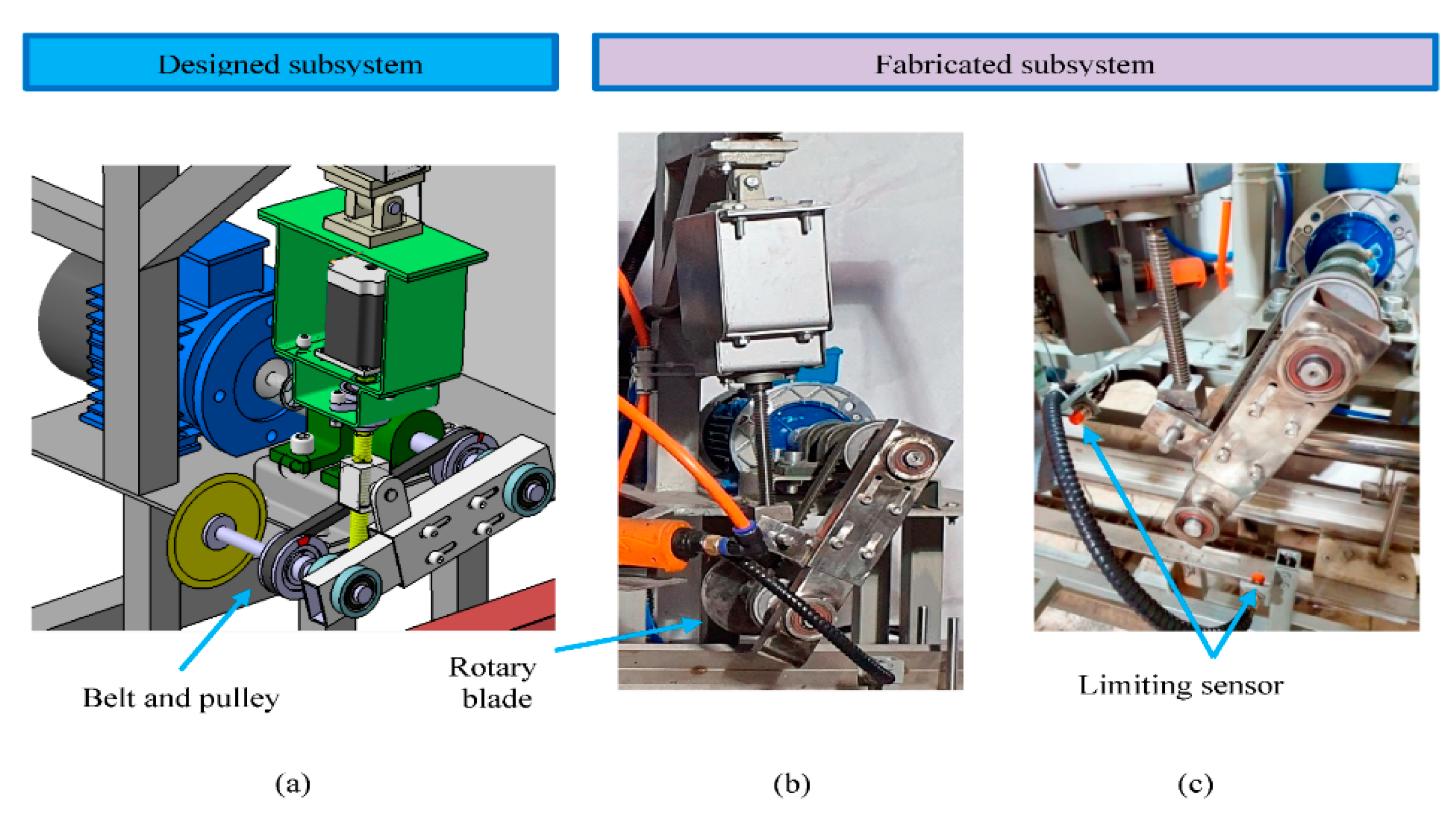
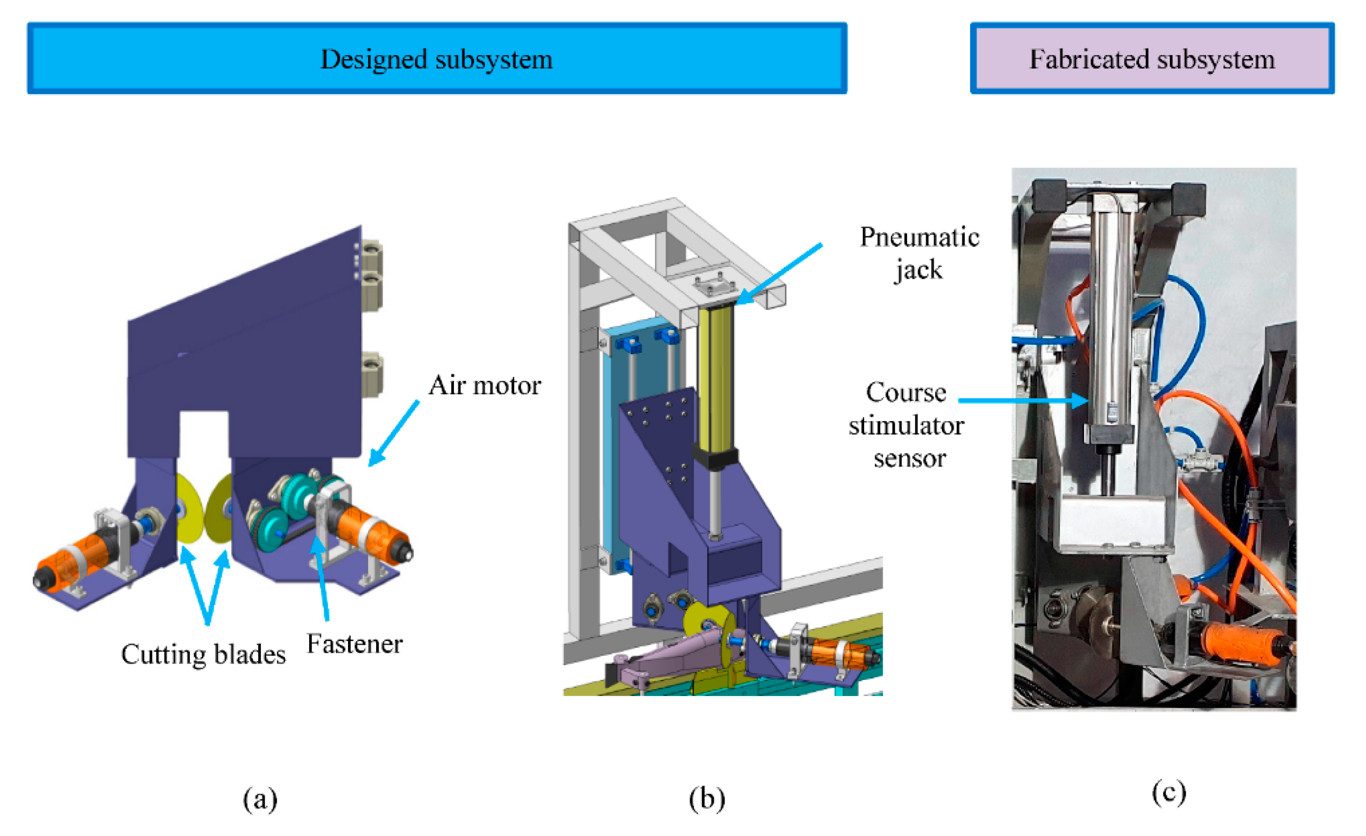
2.2.2. Belly-Cutting Subsystem

The function of this subsystem is to make a longitudinal incision in the trout belly from the beginning of the anal fin to the pectoral fin. After extracting the required dimensions, the first step in device operation is to make a longitudinal incision in the abdomen of the fish from the anal fin to the pectoral fin based on fish size. By sending the commands from the control unit to the stepper motor, the carrier arm moves downwards, and then, the rotating blade cuts the belly. Figure 6 shows the position of the belly-cutting subsystem in the machine together with its components.

2.2.3. Head-Cutting Subsets

Since the fish is moving along the system, it is necessary to provide the best head-cutting condition. In order to have a proper cut, a fast and precise cut must be developed. Therefore, a pneumatic jack was used for the head cutter subset. As mentioned before, when the grippers reach the beginning of the guide rails, the fingers contact the rails and the fishtail stocks between the gripper clamps. At this point, any clamped trout is pulled along the system. Therefore, to define the system processing capacity (fish per minute); it is necessary to determine the optimal working speed. By knowing the linear velocity of the conveyor, the penetration velocity of the cutting blade will be investigated. In fact, the speed at which the cutting blade approaches the fish is directly related to the fish transferring speed. The designed head-cutting subsystem is presented in Figure 7.

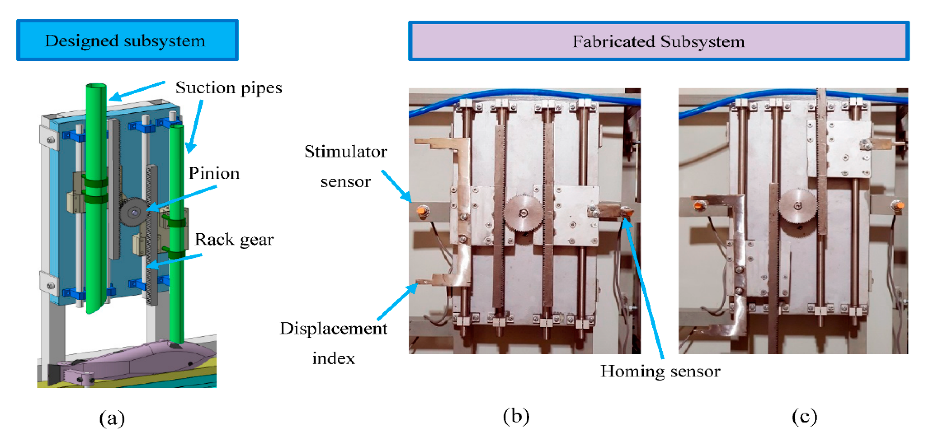
2.2.4. Gutting Subsystem

When the fish reaches the gutting position, the stepper motor is activated by receiving the start command from the control unit and rotates in clockwise and counterclockwise directions depending on fish size. In case the size of the fish is determined as small by the machine vision section, the narrower tube enters the fish belly. In fact, the stepper motor is rotated counterclockwise, and due to the engagement of the pinion with the rack gear, the set of sliders together with the suction tube move toward the fish. The gutting subsystem is presented in Figure 8.

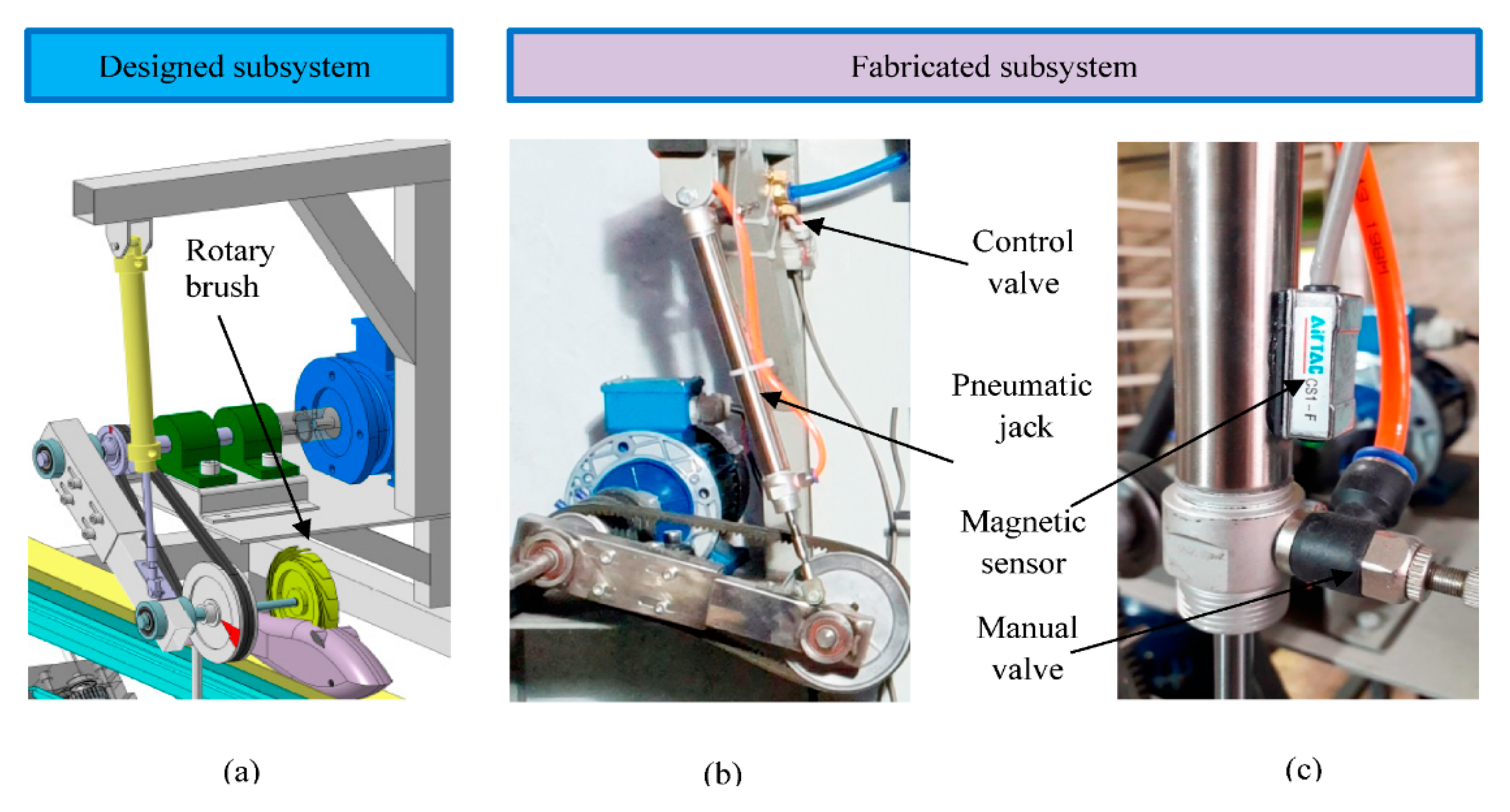
2.2.5. Cleaner Subsystem

This subset is designed to clean the inside of the fish belly and remove any material attached to the fish spine. When the fish reaches the cleaning position, the command is transferred to the pneumatic jack from the control unit and performs the cleaning operation by lowering the jack. The time duration in which the pneumatic jack is extended is directly related to the fish length. As the fish passes in front of the cleaning station, the jack retracts to the initial position. The cleaner subsystem is presented in Figure 9.
The function analysis is presented in Figure 10. As shown in this figure, at the initial step, the fish is gripped by a clamp. Then the fish is carried along the machine for further processing. By passing the fish in front of the camera sensor, the signal is sent to the controller. Then, the controller sends the received data to the interface (Matlab software) via TCP_IP protocol. A frame of the camera is captured immediately and saved for further process. In the next step, the extracted data return to the controller and are reserved specifically for each trout sample. As the gripped fish is carried along the machine, the sensors in each of the stations are stimulated and receive the related information from the labeled pack of the data. Regarding the length and feeding rate, the functioning arms cut or clean the trout with subsequent delays and speeds.

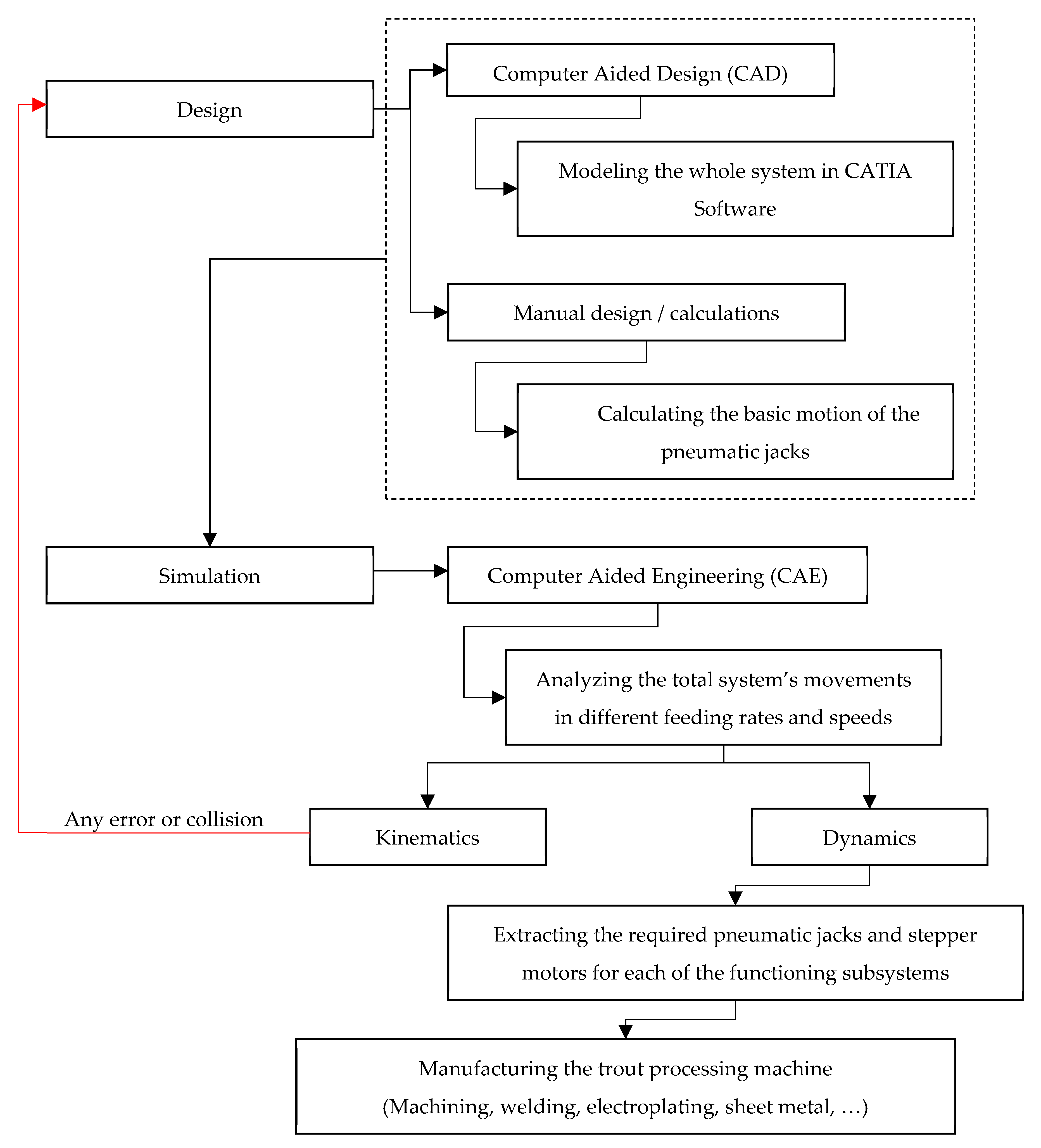
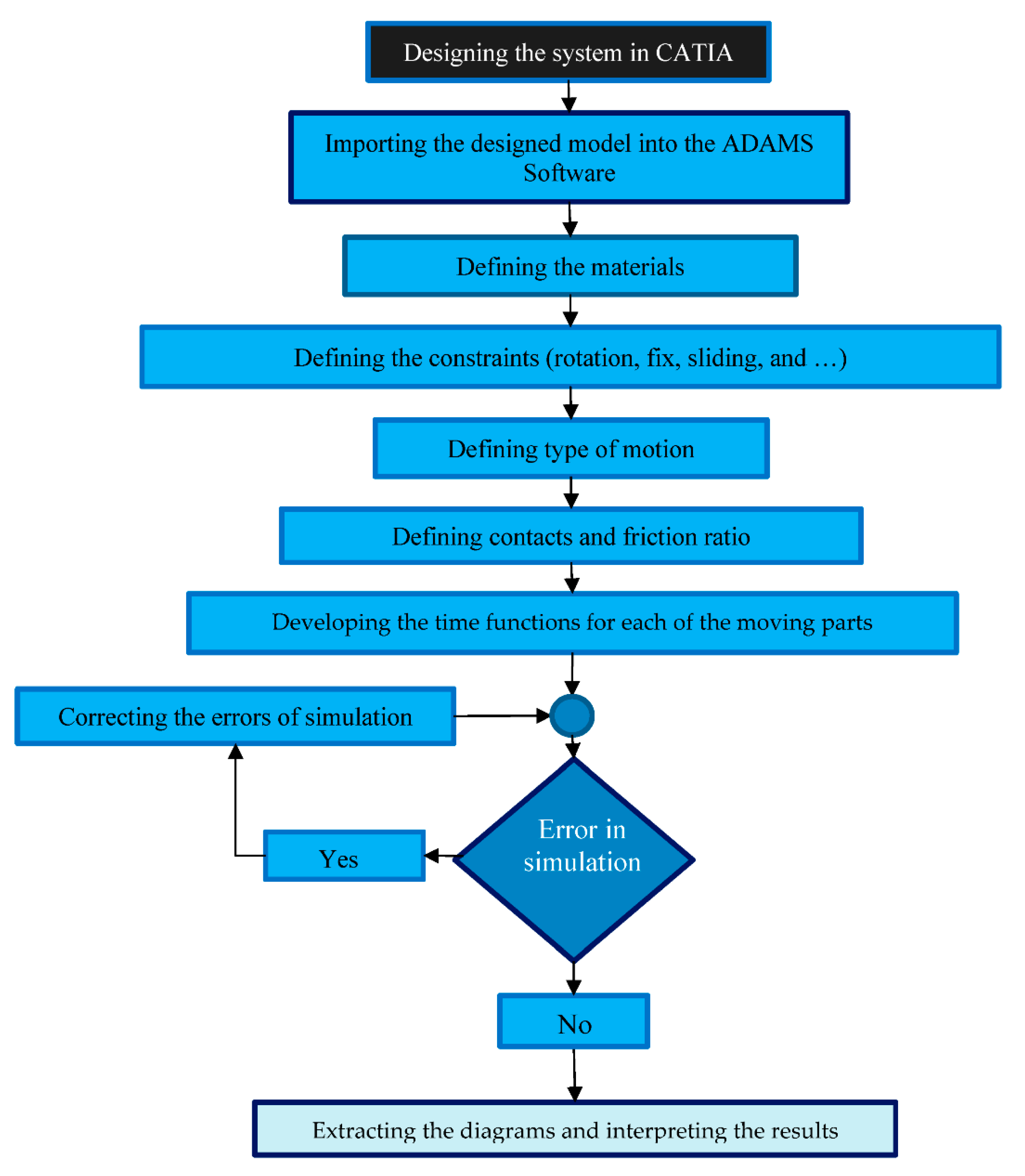
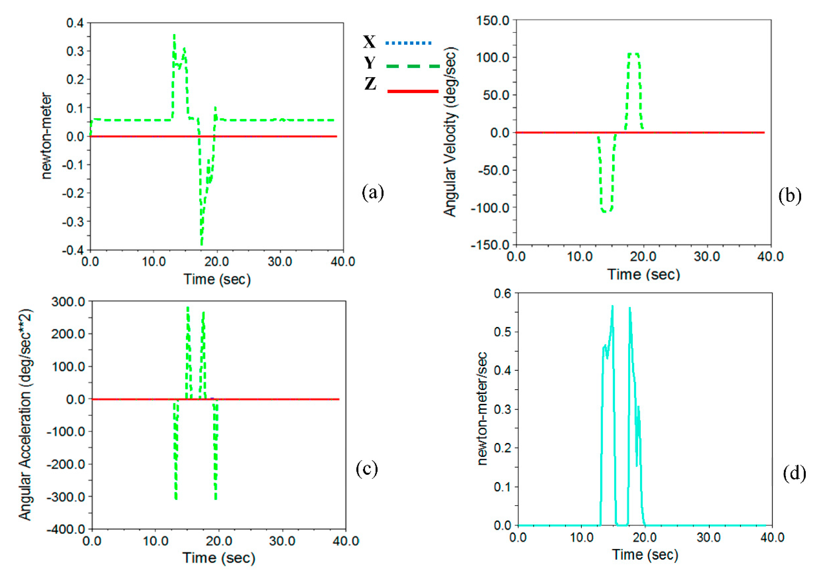
2.3. Device Simulation, Kinetic and Dynamic Analysis and Extracting the Torques of the Motors and Forces of the Pneumatic Jacks

After designing the system in CATIA software, it was necessary to choose the motors and pneumatic jacks. Therefore, it is required to calculate the required torque and rotational speed of stepper motors and the force and speed of pneumatic jacks.
The simplest method is to design all the parts and define their weights to calculate the forces using the conventional method and numerical calculations. This method is applicable when the dynamic parameters are calculated for a single part or, in some cases, the limited number of parts within the relation. Using this method to determine accurate inertia reaction forces in a multi-body system faces a significant challenge unless the problem is simplified. It should be noted that in the simplification method, in addition to the time-consuming computational steps, the reaction forces and the dynamic and static friction conditions will not be the same as the real condition. Therefore, to have closer results to the real operating conditions and reduce the numerical calculations and increase output accuracy, the designed system in CATIA software was imported to ADAMS 2017 software and simulated for dynamic analyses. The simulation steps in the software are presented in Figure 11. The simulation process and extracting dynamic diagrams are presented in Figure 12.
After importing the designed model into simulation software, the first step is to name all parts. The related constraints were assigned for all the parts, and any possible errors were solved. At the next step, the associated motions for the moving parts were considered. For this purpose, a rotational motion was considered for the stepper motor’s hinge in the belly-cutting and gutting subsystems. Likewise, for the linear moving parts, pneumatic jacks, and suction tubes, the linear constraints were considered.
In some parts of the device, to determine the constraints and types of movement, it is necessary to consider the collision between the components involved. This collision was considered between the pinion and the rack gear in the gutting subsystem. The Columbus friction model was used to determine static and dynamic friction between the parts. As the power screw and nut in the belly-cutting subsystem are both made of steel, grease lubrication will be used between these parts. The static friction coefficient was considered to be 0.16 for steel–steel contact [26]. Also, the dynamic friction coefficient was set to 0.08 [27]. For other dry parts of the device, the values of static and dynamic coefficients of friction were considered to be 0.1 and 0.2, respectively.
In order to determine the motion of the moving parts, the “Step” function was applied. As the fish enters the machine, trout size is extracted and the cutting points are defined using machine vision. The rotary cutter creates the longitudinal cut in the belly-cutting subsystem in the first stage. In the next step, the trout is beheaded and gutted. In this regard, it was necessary to consider the sequences of each operator in the simulation.
Therefore, four-movement steps were considered for each of the four operators of the device based on the movement time and rotational and linear speeds. Each pair of steps was considered for each operator’s round trip. For example, the belly-cutting stepper motor start runs based on the written step function. As soon as the arm reaches the end of the path, the second step is applied to control the speed and acceleration. The same steps were also considered for the returning path. As the operator reaches the end of the path in the first run, the arm stops equal to the time required for cutting the trout length. This time is considered between the second and third steps. By finishing the cutting process, the arm returns to the initial position based on the defined speed to complete the fourth step. In this step, when the cutting blade arm reaches the end of the path, a stop command is issued to the stepper motor. In the simulation process, for all of the arms and moving parts, a motion function is considered so that all the contacts, collisions, and moving paths are visible. In such a condition, the timing of arms and actuators is set in an optimized condition. Therefore, by trial and error, the motions in the real system face the least errors and collisions.
Since the minimum and the maximum number of fish is considered to be 4–10 fish per minute, the simulation of the device is performed for the minimum and maximum number and the average number of the fish (4, 7, and 10 fish per minute). To perform the simulation in these conditions, some preliminary considerations and calculations are required. For example, it was necessary to determine fish transfer speed in the canal in terms of fish per minute, because the operator’s speed, performing all calculations, and writing step-functions will be undertaken based on fish transfer speed.

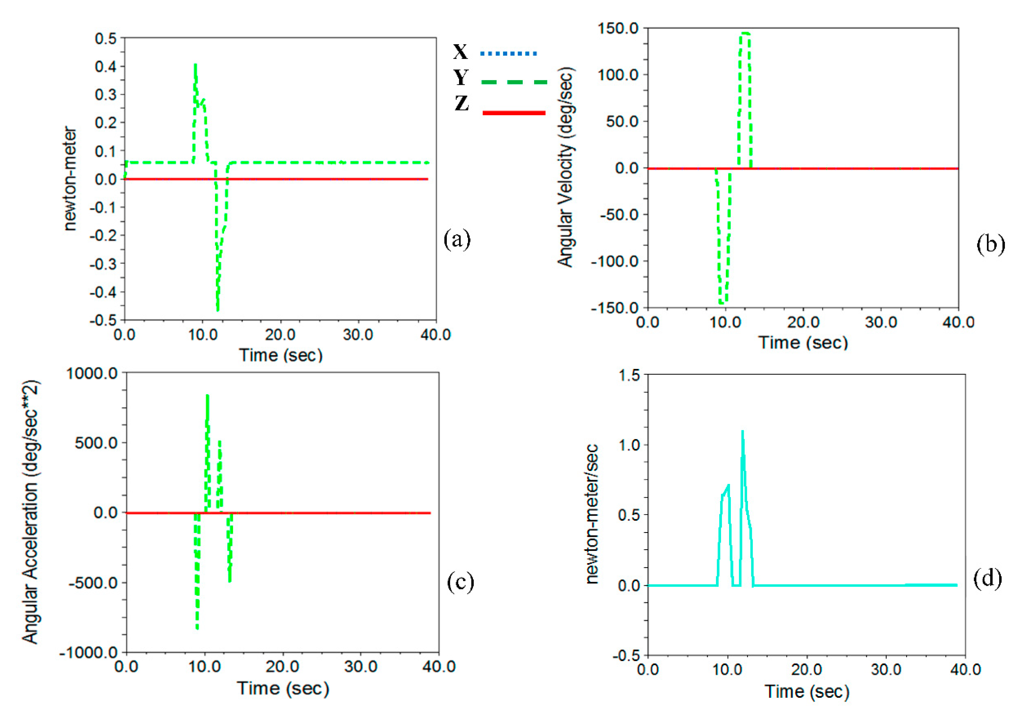
2.3.1. Calculations Related to the Stepper Motors of the Belly-Cutting and Gutting Subsystems

To determine the required torque to actuate the cutting arm and gutting tubes, the system was simulated. Considering the working conditions in the system, all the necessary parameter and considerations such as static and dynamic friction coefficients, any collisions, and all the constraints, were incorporated and motion simulation was performed.
Since the linear velocity of the fish varies in different feeding capacities, it is necessary to bring the cutting arm closer to the fish concerning linear transmission speed. It should be mentioned that the belly-cutting time at which the arm is in the cutting position also concerns the fish transfer speed. In addition to determining motor torque, rotational speed, acceleration, and energy consumption were obtained. Finally, the maximum torque required for system functioning at a capacity of 10 fish per minute was selected to determine stepper motor characteristics in both belly-cutting and gutting subsystems.
A power screw was used to move the cutting arm. Due to the self-locking property of the power screw in the non-working condition, no force will be applied on the stepper motor in idle condition. Since the gutting subset has a different structure, it was necessary to use a stepper motor with a gearbox system due to the inertia of the moving parts so that the suction tubes would stop as soon as the motor stops.

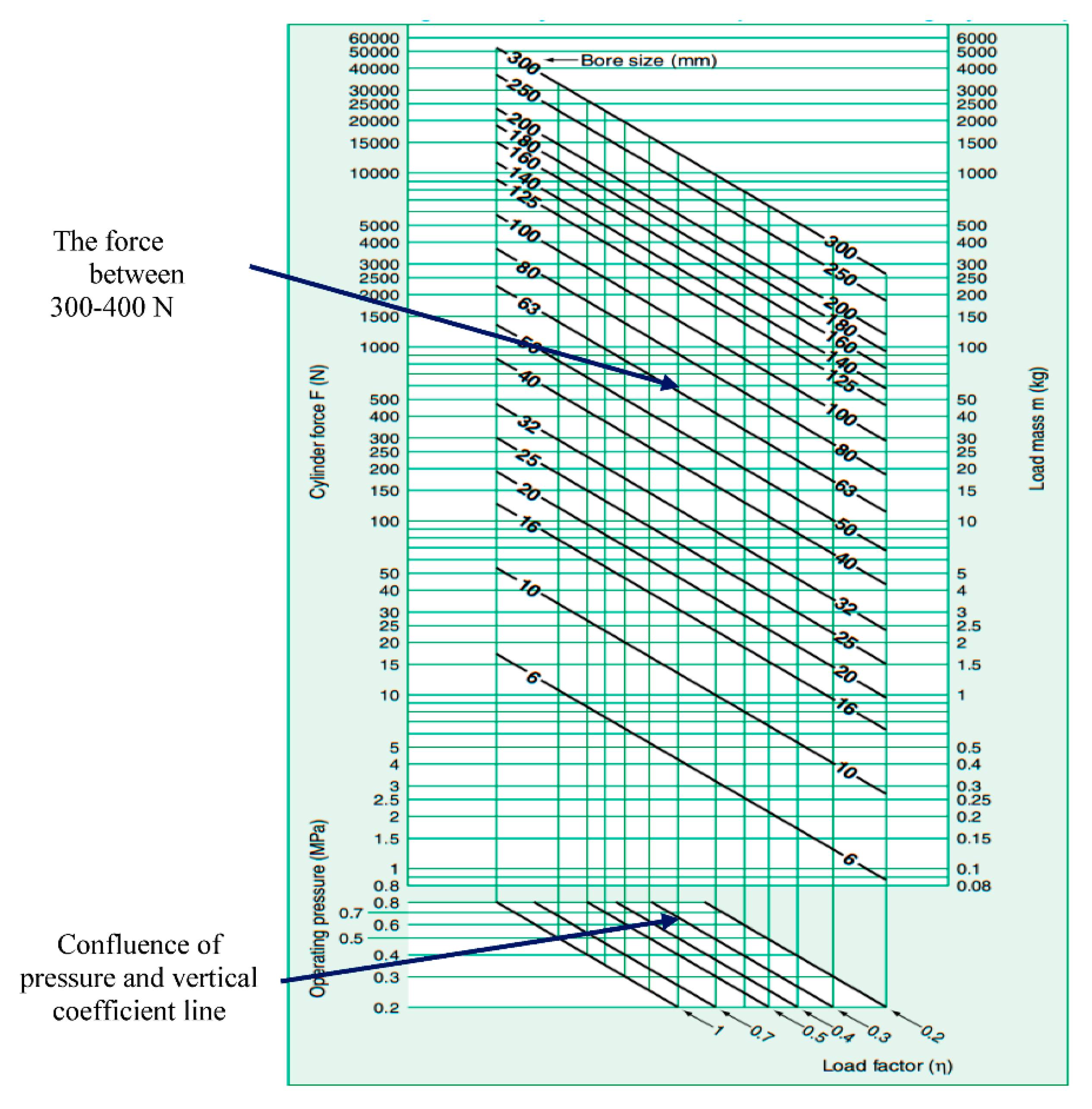
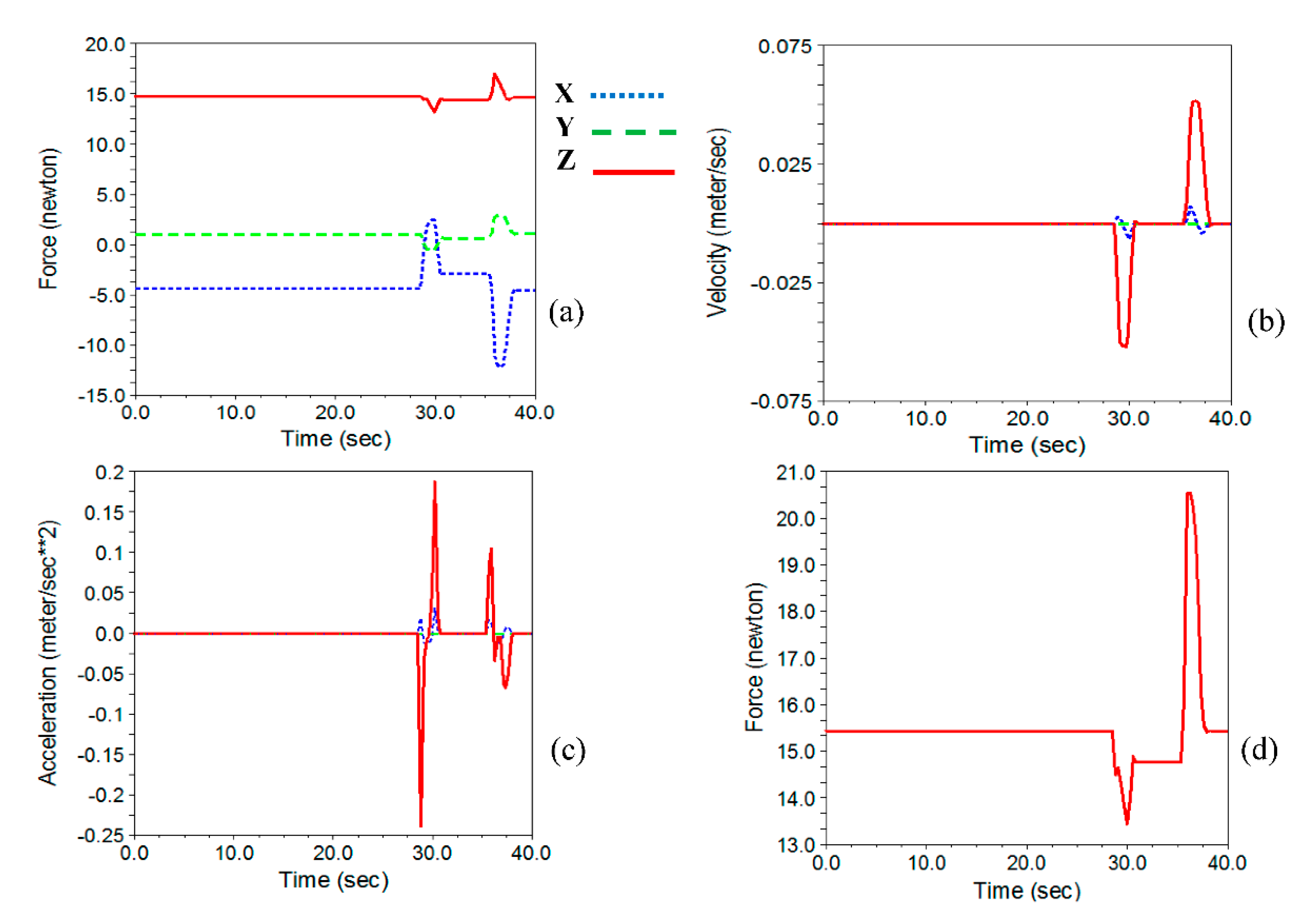
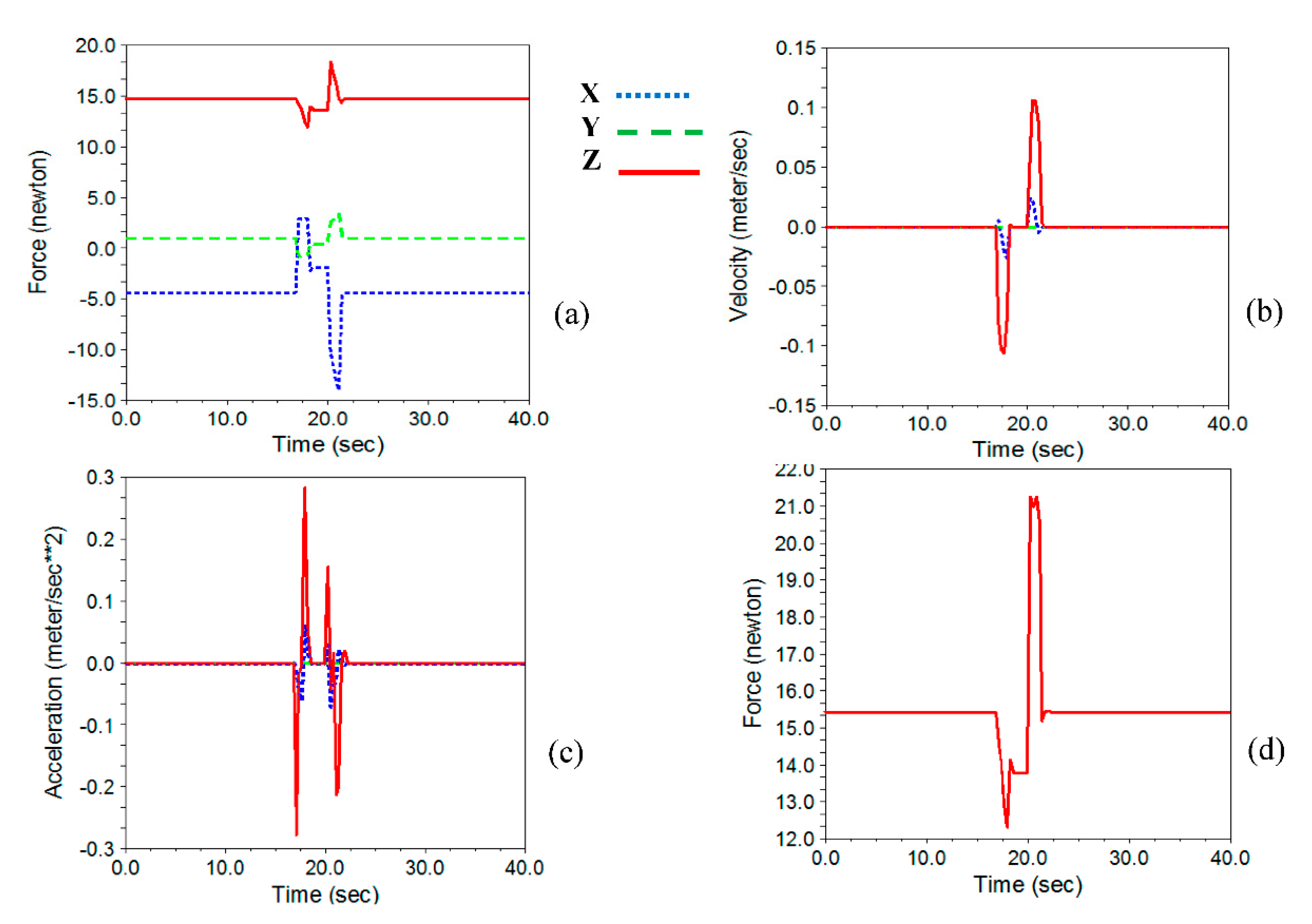
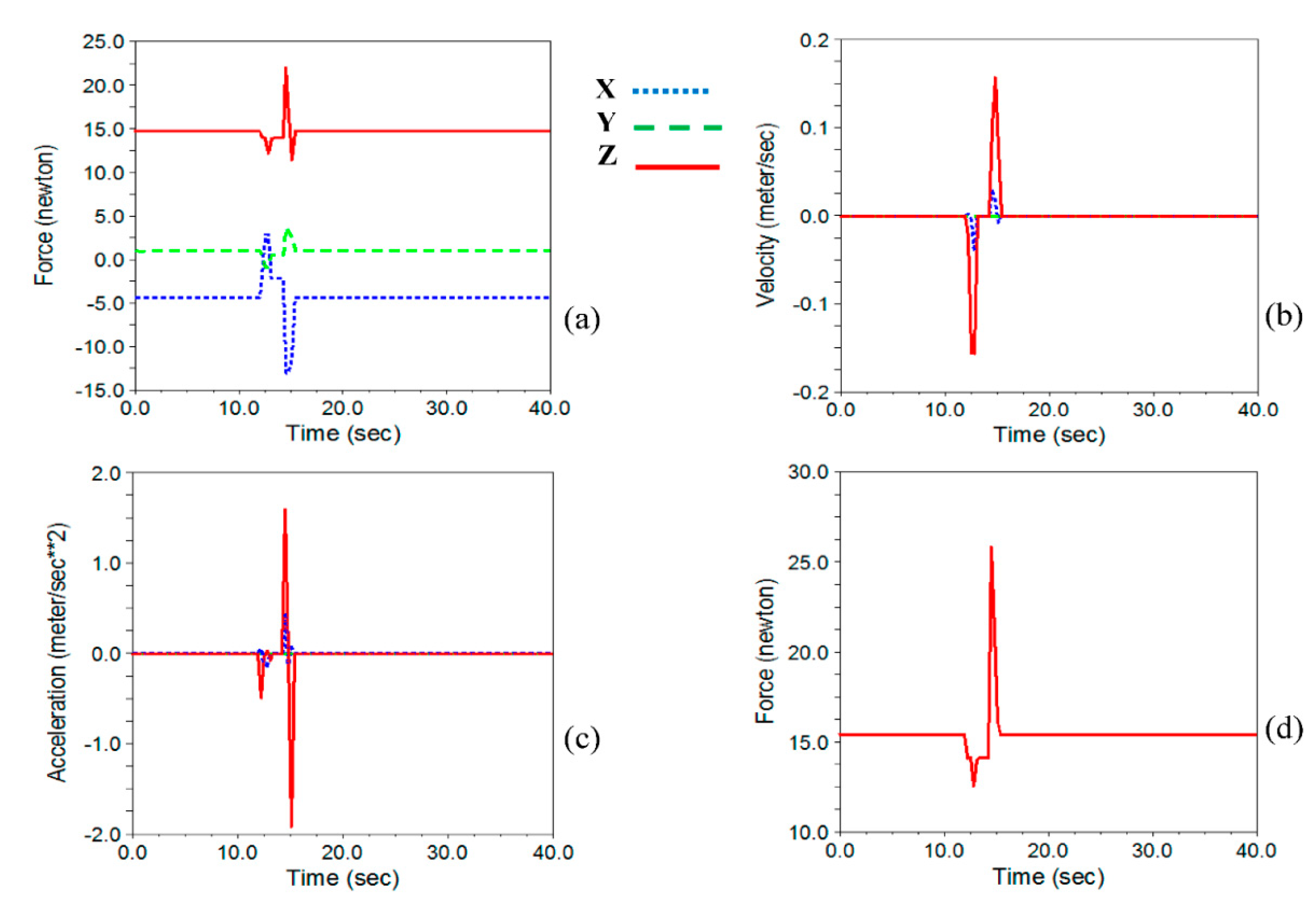
2.3.2. Calculations Related to Pneumatic Jacks of Head-Cutting and Cleaner Subsystems

Two pneumatic jacks were applied in a trout-processing system in head-cutting and cleaning subsystems. As the piston moves downwards during the extraction step, the jack is expected to prevent the subset from free falling. To know whether the pneumatic jack will empower or prevent free fall, we investigated the piston velocity in free-fall conditions from a height of 180 mm. The falling situation is presented in Figure 13. In this figure, IP, SP, and FP are the initial, start, and final positions of the head-cutting subsystem.
The following are the equations for calculating the final velocity of the head-cutting subset in a free-fall condition. According to these relationships, considering the weight of all stimulus parts was regarded as a single mass. By simplifying the falling conditions, the penetration speed in the initial contact and termination step was calculated.
U 0 + K 0 = U 2 + K 2
m · g · h 0 + 1 2 · m · v 0 2 = m · g · h 2 + 1 2 · m · v 2 2
g · h 0 = 1 2 · v 2 2
9.81 × 0.18 × 2 = v 2 2
v 2 = 1.88
In these relations, ‘U’ and ‘K’ are potential and kinetic energies in terms of (J), m is body mass (kg), ‘v’ represents body velocity (m s−1), ‘h’ is the falling height (m), and ‘g’ represents gravitational acceleration (m s−2). According to the energy conservation law, the sum of kinetic and potential energy at two points at the beginning and end of the motion path must be equal (Equations (2) and (3)). After simplifying the relationship, the velocity value at the end of the path resulted in 1.88 m s−1. Assuming that the head-cutting subset has a free fall, by substituting the velocity values for ‘v1′ and ‘v2′, the required time for complete cut will be obtained using Equations (7) and (8).
v 1 = g · t 1 + v 0
v 2 = g · t 2 + v 0
By setting the values of 1.25 m s−1 and 1.89 m s−1 for ‘v1′ and v2 in Equations (7) and (8), t1 and t2 were calculated as 0.13 s and 0.19 s, respectively. The blades will travel the distance from IP to FP (180 mm) in 0.19 s in the vertical direction. Also, the head-cutting blades will travel ‘a’ distance ‘b’ in 0.13 s. At this distance, the cutting blades will descend freely to reach the fish in the SP position. Considering the fish’s average width of 100 mm, the cutting time from SP to FP resulted in 0.06 s. It should be noted that the penetration velocities in the SP and FP region are high values; this value is also higher than the maximum speed provided by the pneumatic jack.
Comparing the velocity values in different states, it is not allowed to consider different speed ranges for the piston. Obviously, the least amount of longitudinal displacement of the fish during the cutting process will be achieved at the highest blade penetration speed and the lowest processing capacity. Therefore, a penetration velocity of 500 mm s−1 was considered as the final velocity for cutting blade. Under these conditions, as this speed is considered maximum, the other feeding rates will be processed even better than the maximum feeding rate of 10 fish per minute. By comparing the velocity and time of the free fall with the maximum speed piston speed, it is expected that the piston must exert the opposite force against the free fall. This can also be seen in the output of the ADAMS software. By defining the required force, the pneumatic jack was selected for both the head-cutting and cleaning subsystems. Since the total displacement range of the head-cutting subset is 180 mm, a 250 mm course jack was selected. It should be noted that the amount of applied force was different in jack extraction and retraction courses. The amount of supplied force in extraction and retraction steps is calculated by Equations (9) and (10), respectively.
F e = π × D 2 4 · P · g
F r = π × D 2 d 2 4 · P · g
In these equations, ‘D’ and ‘d’ are the outside and inside diameter of the piston rod in millimeters, ’g’ is the gravitational acceleration (9.81 m s−2), ‘Fe’ and ‘Fr’ are the force of the jack in the extraction and retraction course in Newton ‘N’, and P is the air pressure in terms of ‘bar’, respectively. Since the one-way pneumatic jack exerts more force in the extraction course, it is preferred to use the cylinder in the retraction mode until the next fish arrives, the jack can return to its original position slower than the extraction course.
Assuming the fish moves at a constant speed in the guided canal, the faster the blade penetrates the fish body; the more precise the head cut will result. Knowing that the force exerted by the jack resists the free fall of the cutting sub-section, especially at the end of the course, the designed model is entered into ADAMS software, and all the necessary constraints, their movements, and friction coefficients were entered into the model. Among the tested speeds for the jack, the maximum required force was obtained for the speed of 500 mm s−1. After determining the amount of force, the next step is to select the pneumatic jack. The following items will be considered in selecting the jack:
  • Design factor;
  • Jack force;
  • Load coefficient in vertical operation mode;
  • Air pressure;
  • Speed coefficient.
Considering the design factor, the maximum force was considered 1.5 times greater than the value given by ADAMS software. Therefore, the force is considered equal to 332.45 N in further calculations. If the pneumatic jack is considered to work in a horizontal position with a pressure of 0.8 MPa, a jack with a bore diameter of 32 mm will be a proper option. If the jack is used in the vertical position, the bearing load by the jack will be reduced to 50%. This value can be reduced by up to 20% at high operating speeds. In fact, in addition to considering the design factor, the vertical load factor must also be considered. Also, in order to have an optimal performance at low air pressures, the air pressure of 0.4 MPa was considered in calculations. The pneumatic jack bore size selection graph is presented in Figure 14.
As shown in lower part of Figure 14, by considering the air pressure and vertical operation coefficient, a vertical line was defined. By tracing this line and contacting bore size of 32 mm, the supplied force between 100–150 N was anticipated which was less than the desired force of 332.45 N. Considering the vertical load factor as 0.5 at a working pressure of 0.4 MPa and the impact of the vertical force, an air jack with a 32 mm diameter can supply force values between 100 N and 150 N, which is less than the required value (N45/332).
As a final option, a jack with a bore size of 50 mm can supply the desired force values between 300–400 N. A similar process was performed to determine the second jack in the cleaning subsystem. Hence, at a load factor of 0.5 and air pressure of 0.4 MPa, a jack with a 20 mm diameter to supply active force between 30–40 N was selected in maximum fish-processing rate (10 fish per minute).

2.4. Fabricated System

The final trout-processing machine is presented in Figure 15a. The final system was fabricated after the motion simulation. The components of the system are presented in detail. This system also contains a controlling and machine vision section beside the mechanical design and machine vision section. The rear view and the controlling panel are presented in Figure 15b,c, respectively. In order to control the moving parts, different electronic devices are required: start/stop switches, emergency disconnect switch, sensors, controller, stepper motors, and drives. Inductive and magnetic sensors were used to control operating arms and stepper motor movements. Because the device’s arms’ movement in each of the working steps require unique control, the device control algorithm was written in three parts: initial setup, manual operation, and online automatic function. To develop the controlling algorithm, Siemens TIA Portal automation software and Siemens controller was used.
Since inductive sensors are applied in each of the five subsets (machine vision, belly-cutting, head-cutting, gutting, and cleaning subsets), in case there is no fish in the gripper, the dimensions extracted by machine vision will be calculated as “0”, and the system operators will be standby state without any function (Supplementary Material).

3. Results and Discussion

Since the system is designed, simulated, and fabricated based on the simulation data, the results of the simulation are presented as follows. These calculations are conducted on the piston speed, selecting the belly-cutting stepper motor, choosing the head-cutting actuating piston, defining the gutting stepper motor’s characteristics, and the required force for the cleaning subsystem. The related results are presented below.

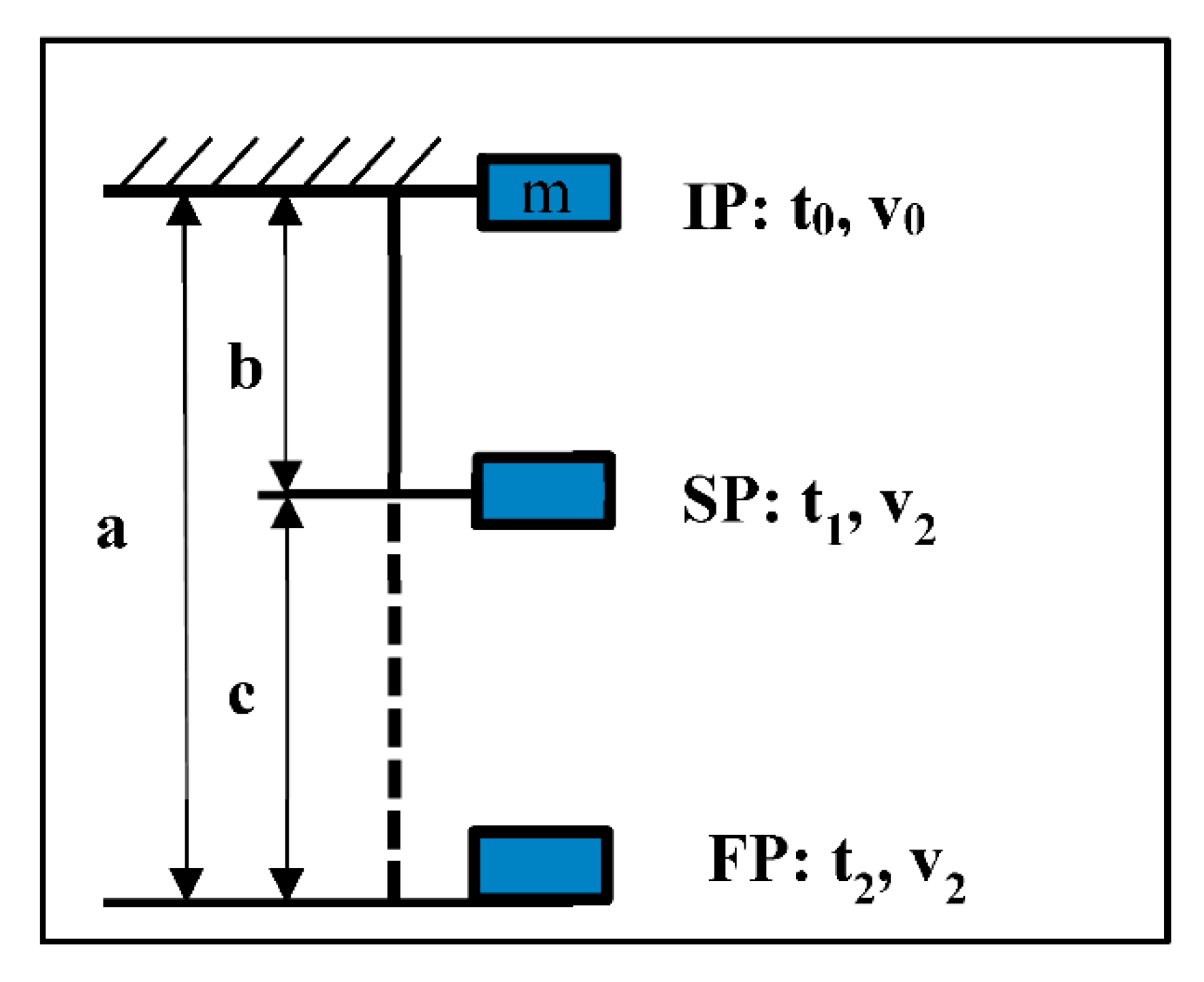
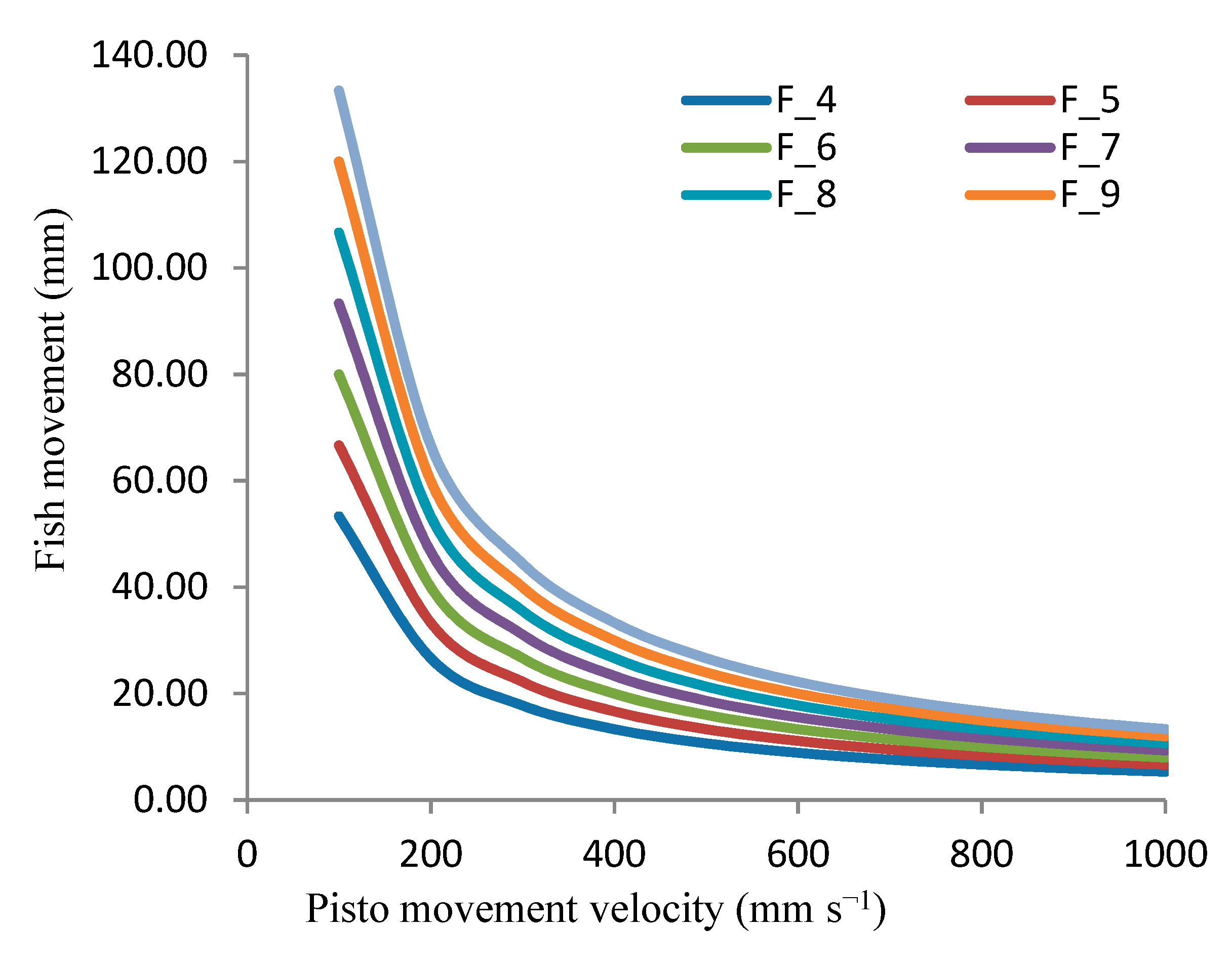
3.1. Piston Speed Calculations

In addition to the analytical results generated by the software, some of the results were calculated in the initial step. This part of the results is related to the working capacity and processing quality of the operators during machine functioning. The results are related to the amount of fish movement in each of the capacities of the device. In Table 2, trout transfer length along the machine is presented in each feeding rate.
As shown in this table, by increasing the feeding rate, the fish transfer speed increases. Since it is desirable to increase the capacity of the system, the appropriate solution is to increase the penetration rate of the blades in the fish. The longitudinal displacement of fish at MF-4 and MF-10 capacity with the piston velocity with 100 mm s−1 was calculated as 53.33 mm and 133.33 mm, respectively. It should be noted that moving the trout as 133.33 mm while moving in front of the head-cutter blades causes separation from the gripper or creates an undesirable cut in the head.
By increasing the blade penetration rate to 900 mm s−1, the displacement values in both MF-4 and MF-10 capacities were calculated as 5.93 mm and 14.81 mm, respectively. These values are suitable for cutting the head, but it should be noted that increasing the speed of the pneumatic jack increases the inertia in the actuator sections, so the rod speed such as 400 mm s−1 and 500 mm s−1 is suitable for head cutting. The amount of fish movement in the minimum and the maximum capacity of the device at the speed of 500 mm s−1 are 10.67 mm and 26.67 mm, respectively. The head of the fish will be cut with a slight deviation from the vertical line, in which the fillet near the neck of the fish will be separated along with the body.
Figure 16 shows fish movement at different jack speeds. As shown in this figure, the displacement values at a particular capacity, such as the F-4, decrease non-linearly by increasing jack speed, so that at piston speeds in the range between 100–200 mm s−1, fish displacement decreases with a high slope while the slope decreases at speeds of 600–1000 mm s−1.
This figure also shows that, at low transfer speeds, there is a large difference between the fish movement values, whereas as jack speed increases, the difference between these values decreases. In other words, considering the balance between the jack speed and the amount of fish displacement, it is appropriate to consider higher velocities of the carrier jack, but it should be noted that at higher jack velocities, the difference between the displacement values decreases. Due to the higher inertia of the moving parts and the high vibrations in the system, electing jack speeds such as 400–500 mm s−1 is a suitable speed for the head-cutting blade set.

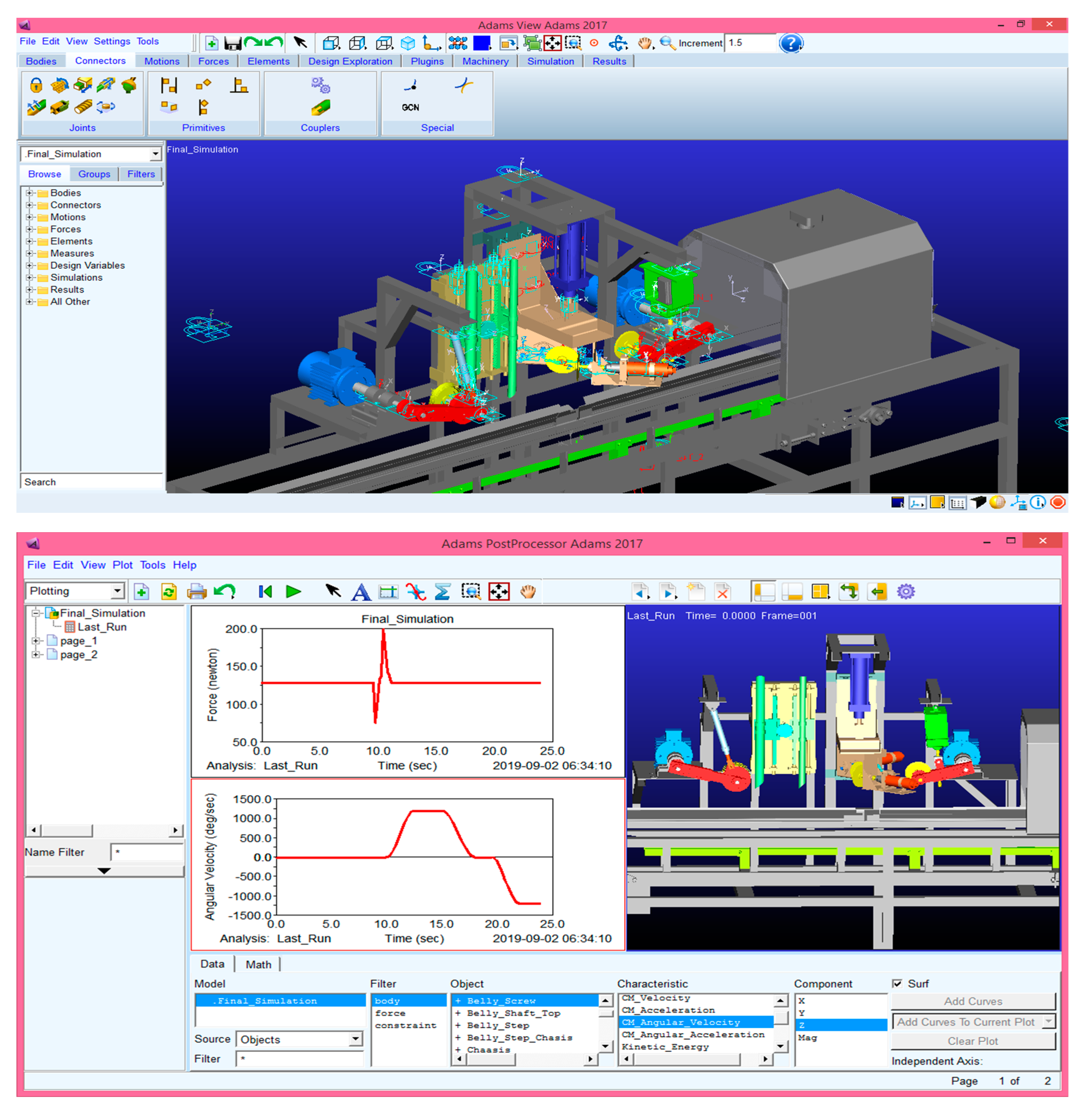
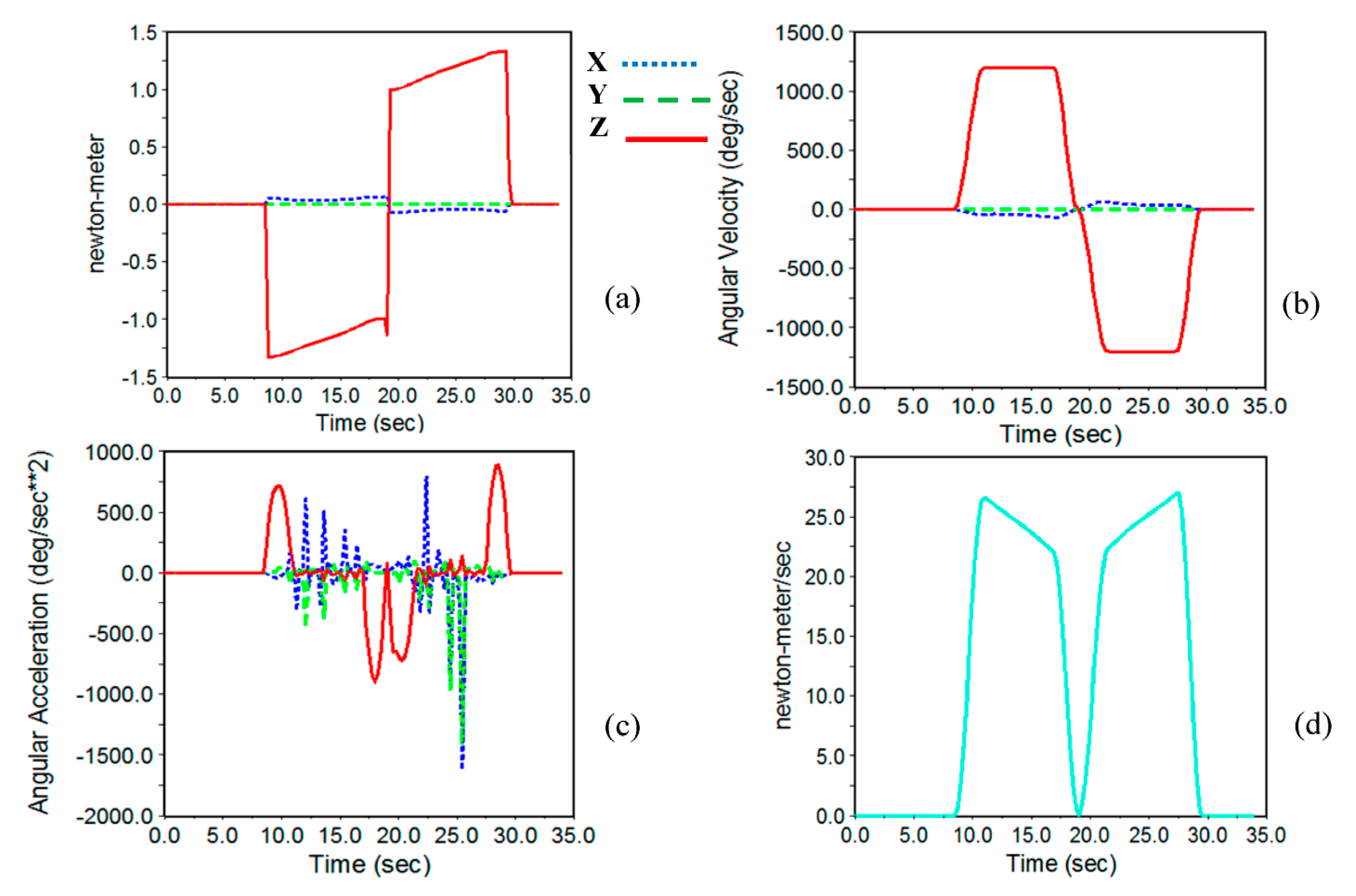
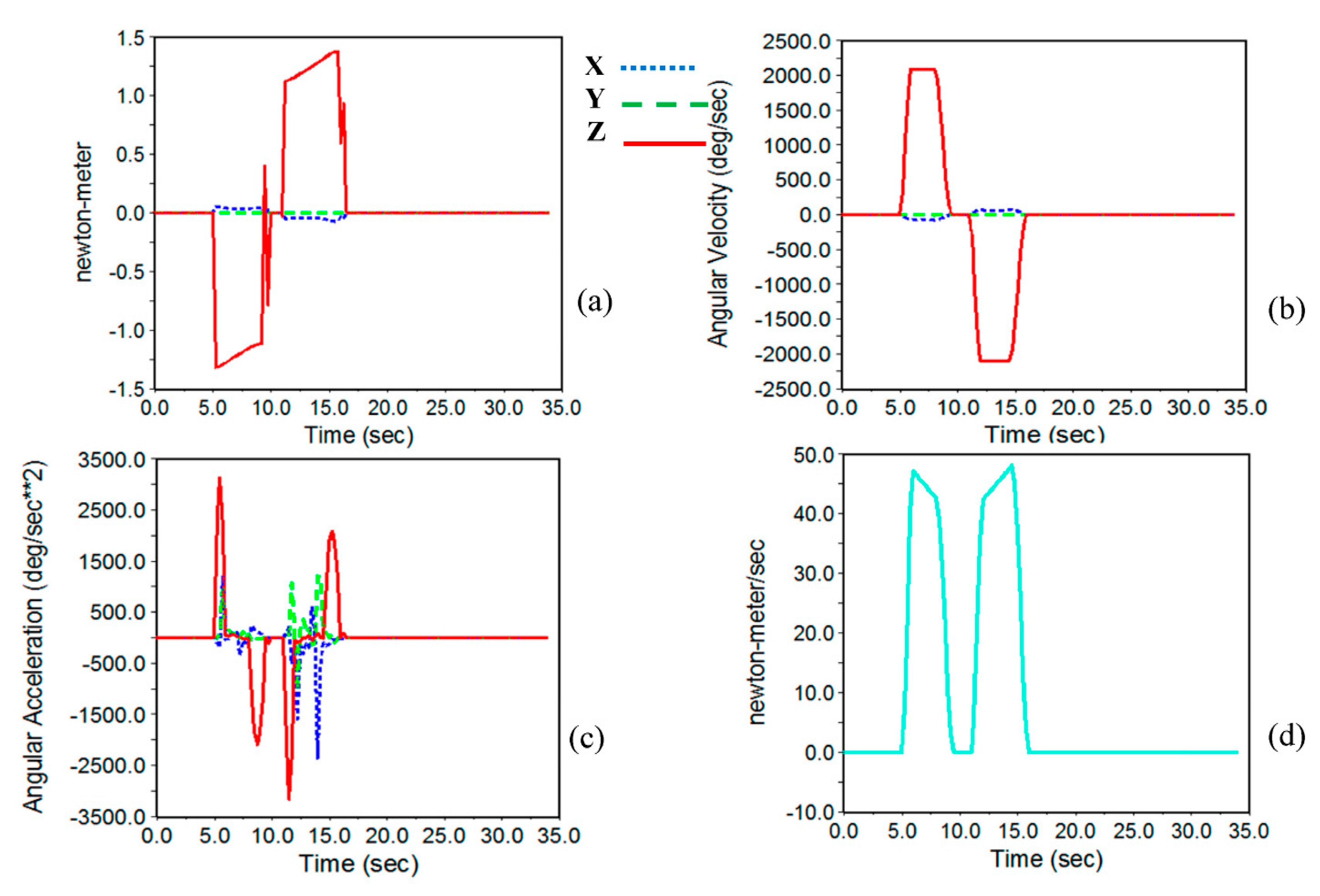
3.2. Results of Simulation

The results of system simulation are presented in the following. In order to reach an optimized design and observe the force, torque, and speed trends, the system was tested in three feeding rates. These capacities are the minimum, maximum, and the average number of fish per minute (4, 7, and 10 Fish/min), respectively.

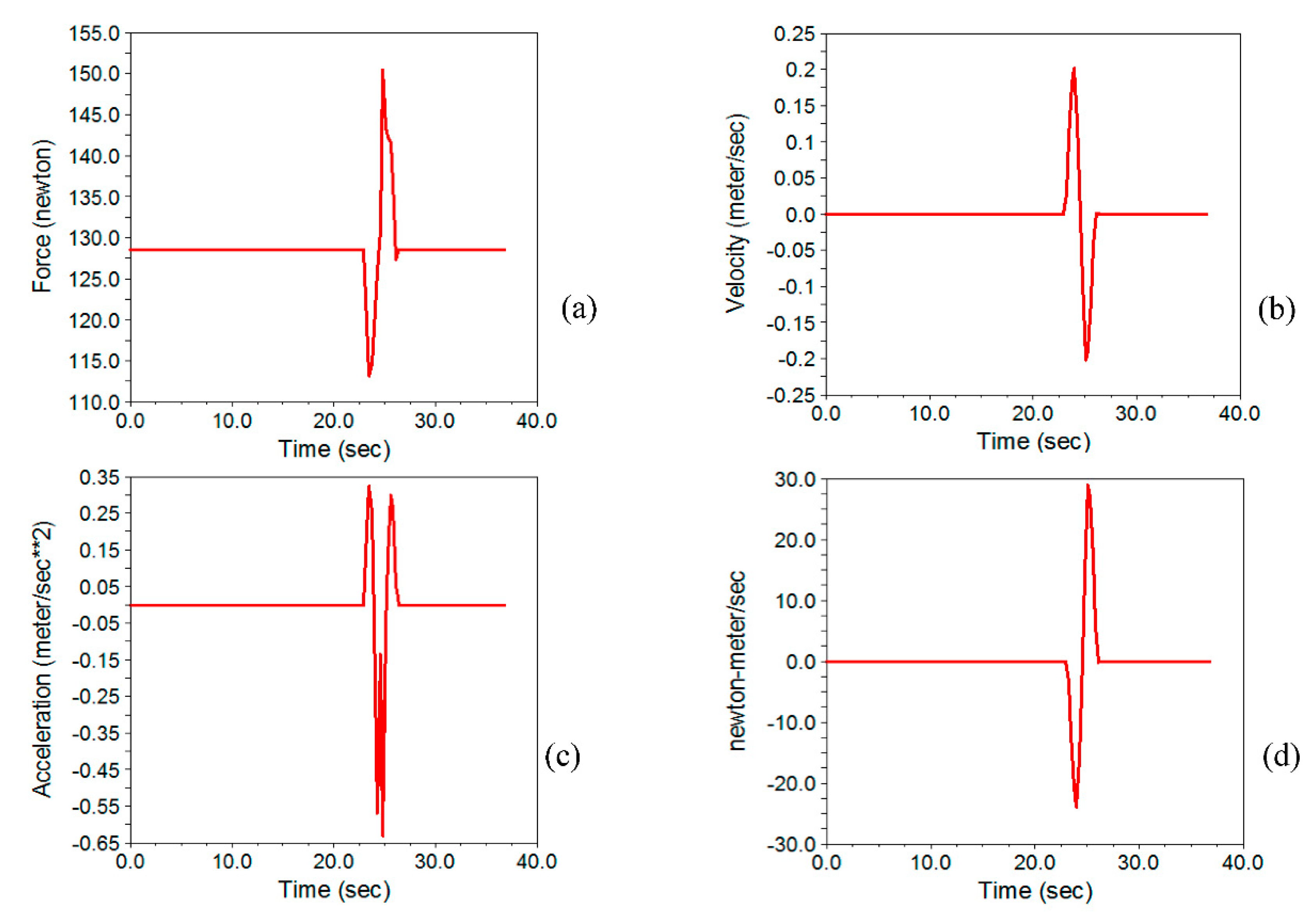
3.2.1. Selecting the Stepper Motor of the Belly-Cutting Subsystem

The belly-cutting subsystem is a subset of the machine in which a longitudinal incision is made from the anal fin to the fish head using a rotating blade mounted on the main arm.
In Figure 17, Figure 18 and Figure 19 the motion simulation results are presented for the belly-cutting subset. In these figures, the characteristics of the required stepper motor are determined. These characteristics are the required torque for cutting operations, angular velocity, angular acceleration, and energy consumption in three feeding rates. In these figures, blue dotted, green dashed, and red solid are the components in X, Y, and Z directions.
As shown in these figures, the angular velocity and acceleration around the Z-axis are maximum. Also, the required energy increases by increasing angular velocity. The maximum torque values in three capacities of 4, 7, and 10 fish per minute were 1.334 N m, 1.378 N m, and 1.431 N m, respectively. Therefore, to select the required stepper motor maximum amount of torque (10 Fish/min) was selected. By considering the design coefficient of 1.25–1.5, the required torque for the stepper motor is in the range of 1.79–2.145 N.m. Therefore, a Nema 23 stepper motor (57PH20-0.2 kg m) stepper motor with a torque 1.96 N m was selected. Considering this stepper motor, a design factor of 1.37 is obtained, which is acceptable for the device operation.
In Figure 17b−d the angular velocity, acceleration, and energy consumption are presented, respectively. As shown in these figures, by increasing the fish feeding rate, the blades are about to penetrate the belly at higher speeds, requiring higher velocity and acceleration. As shown in these three figures, the maximum angular velocity, acceleration, and energy consumption are related to 10 fish per minute. Due to the sufficient time interval between the fish grippers, there is enough time to return to its initial position.

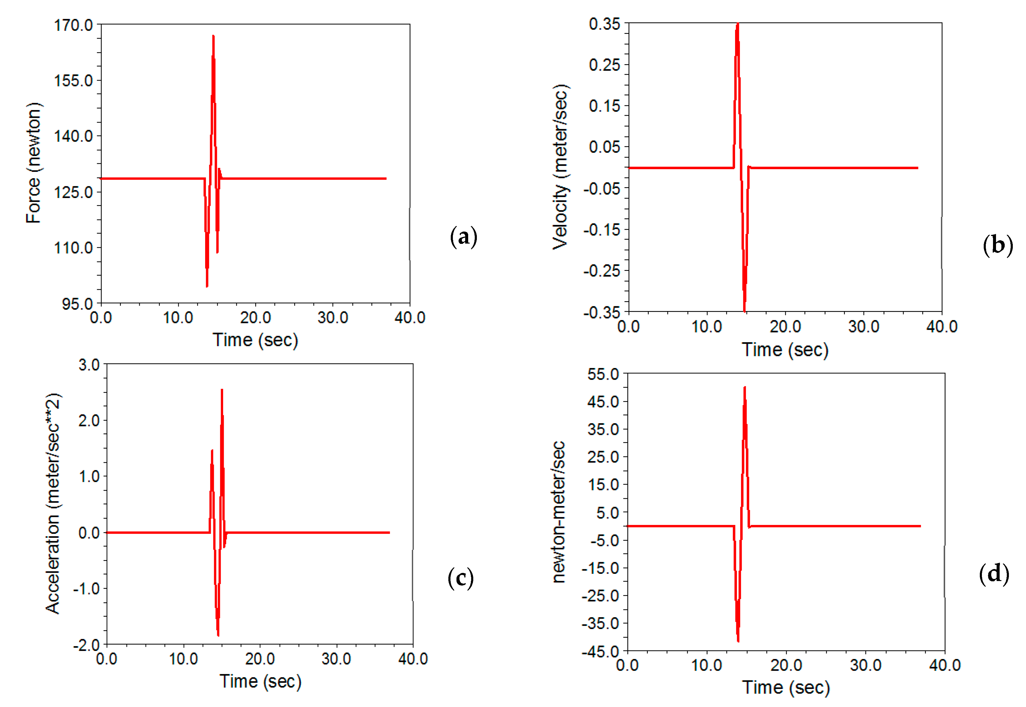
3.2.2. Selecting the Pneumatic Jack of the Head-Cutting Subsystem

The results for the simulation are shown in Figure 20, Figure 21 and Figure 22. In order to ensure successful head cutting, it is necessary to synchronize the fish feeding rate and cutter penetration. In fact, the faster the jack penetrates and the slower the fish moves, the better the cut is done. Although the lower transfer speeds result in a proper head cut, it should be noted that it results in low system operation capacity.
By comparing the final velocity of the free fall for the head-cutting jack at the end of the cut path, it is obvious that the air jack prevents the moving parts from free-falling. The maximum required force in three capacities resulted in 149.83 N, 164.33 N, and 221.63 N, respectively. As shown in Figure 20, the amount of required force for the jack in the stop mode is between 127.5–130 N to compensate for the subset weight.
When the fish reaches the head-cutting position, the jack is activated and moves downward. As moving downwards, the required force decreases, and by reaching the end of the cutting path, the force increases to the maximum amount of 149.83 N. This force value resulted in a feeding rate of four fish per minute and the jack penetration speed of 200 m s−1. Besides the required force and speed of the pneumatic jack, the acceleration and energy consumption in the simulation time interval in the three working capacities are shown in Figure 20c,d. Similarly, the amount of required force in 7 and 10 fish per minute resulted in 164.33 N and 212.63 N at the blade penetration speeds of 350 m s−1 and 500 m s−1, respectively. Similar results for the two penetration velocities of 350 m s−1 and 500 m s−1 are shown in Figure 21 and Figure 22. The maximum required force to provide a speed of 500 mm s−1 resulted in 2221.63 N. By multiplying this force by 1.5 as the design coefficient, the final force size on which the jack resulted in 332.45 N. Refer to the diagram presented in Figure 22.
Based on the operational position of the jack (vertical or horizontal) and air pressure, the size of the air jack was determined based on the maximum force required to move the head-cutting subset (332.332 N). Since the supplied force in extraction mode is more than the retraction, the pneumatic jack was selected based on the amount of the force that the jack can supply in retraction mode so that it can supply the required force while the jack ascends toward the initial position. On the other hand, it should be considered that the operating speed of the jack is one of the most important characteristics for determining the size of the jack. By following the line obtained from the intersection of the axis related to the vertical operating coefficient of 0.5 and the axis of air pressure, the 0.4 MPa vertical line is determined.
By contacting this line with the force axis equal to 332.45 N, a cylinder with an internal diameter of 50 mm was selected. The minimum displacement of 180 mm was considered to provide successful head cutting and avoid any contact with the moving grippers, but to ensure any contact, among two different courses of 200 mm and 250 mm, the larger size was installed in the system. Therefore, the penetration rate of 500 m s−1 was considered as the final penetration rate of the cutting blades. This condition will be the desired condition for head cutting in lower feeding rates. On the other hand, choosing this speed can result in an acceptable head cutting without any considerable fillet loss.

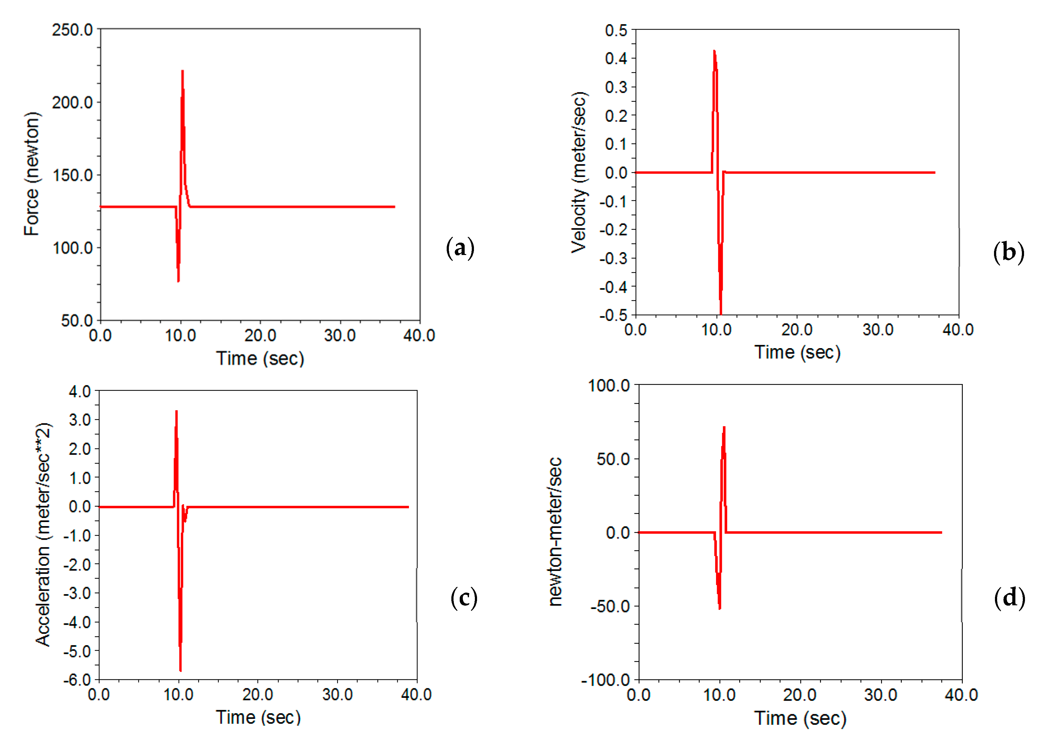
3.2.3. Selecting the Stepper Motor of the Gutting Subsystem

The motion simulation results for selecting the motor characteristics in three feeding rates are presented in Figure 23, Figure 24 and Figure 25, respectively. In all the figures, the required torque, angular velocity, angular acceleration, and energy consumption are presented for each of the feeding rates. The diagrams present both clockwise and counterclockwise motions.
As shown in these figures, the maximum required torque to move the suction pipes in a vertical direction resulted in the highest working capacity. In this section, when the fish reaches the suction position, the stepper motor rotates in clockwise and counterclockwise directions depending on the fish dimension. As soon as the tubes open, the material inside the trout belly is evacuated. Using two discharge pipes, the required torque for lifting two pipes is less than the condition at which the stepper motor controls one suction tube.
The required torque increases by increasing the angular velocity; whereas, in the maximum angular velocity, the maximum amount of required torque in the three input velocities was 0.226 N m, 0.386 N m, and 0.465 N m, respectively. Since the maximum required torque resulted in 0.465 N m, the required torque was estimated to be 0.698 N m by considering the design coefficient of 1.5. As the pinion is connected directly to the rack gear, a gearbox mounted stepper motor was applied to move the suction pipes. Therefore, a stepper motor with a reduction ratio of 1:18 with a total maximum torque of 0.8 N m was applied.

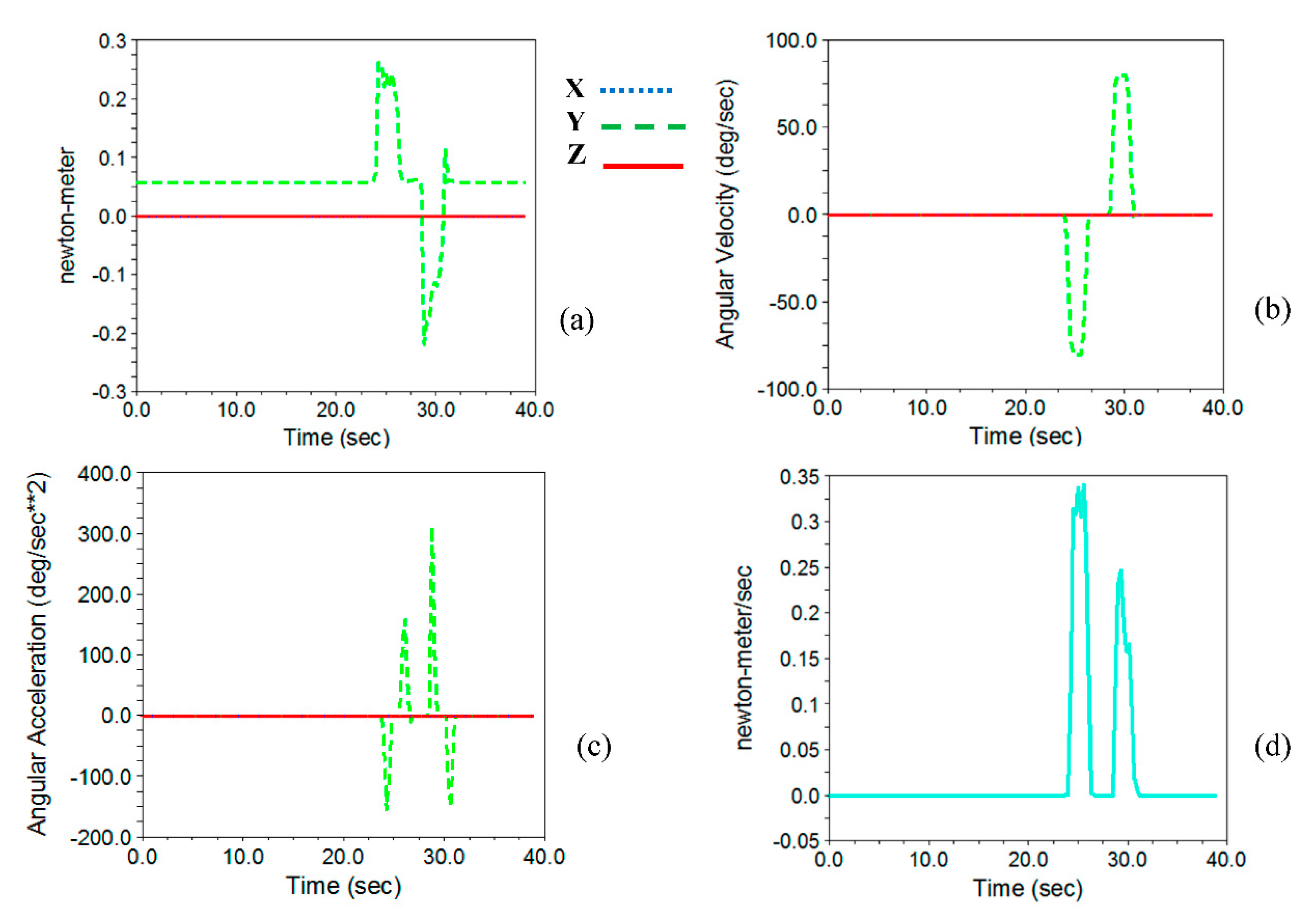
3.2.4. Selecting the Pneumatic Jack of the Cleaning Subsystem

After evacuating the belly content, it is necessary to clean any sticky materials attached to the spinal cord and belly cavity. A rotary brush with a ferry-ribbed edge was driven with an AC electromotor. In order to move the belly cleaner set, it was necessary to use a jack to raise and lower the rotating brush to avoid hitting the fish grippers.
The final stage of the fish processing in this system is to clean the belly content. As long as the clamp reaches the cleaning subsystem, the cutter descends to clean the belly. As long as the fish is moving towards the end of the machine, depending on the size of the fish, the arm is in an operating position based on the fish length. As soon as the fish cleans, the arm returns to the initial position. The results for the output of ADAMS software in three capacities are presented in Figure 26, Figure 27 and Figure 28. In these figures blue dotted, green dashed, and red solid lines are the components in X, Y, and Z directions.
In these diagrams, the force diagram in three directions of x, y, and z (diagram a), the velocity and acceleration (diagrams b and c), and the total force values (diagram d) are presented. As shown in these figures, unlike the jack used in the head-cutting subset, in addition to applying force along the z-axis, force components are also observed in both the x and y directions. The maximum required force to move the arm at the capacity of four, seven, and 10 fish per minute was 20.55 N, 21.26 N, and 25.84 N, respectively. Multiplying the maximum force by 1.5 as the design coefficient, the final force results in 38.76 N. By referring to the diagram presented in Figure 28, the size of the jack was determined based on working position and air pressure by referring to the calculated force (38.76 N). Like the pneumatic jack of the head-cutting subsystem, the retraction mode was selected as the criteria to select the jack. Since the arm operates at a considerable angle to the horizontal line, the vertical operation coefficient was 0.5.
Pursuing the intersection line of vertical operation coefficient and air pressure of 4 bar, the required force value (37.86 N) falls between the possible standard bore sizes of 16 and 20 mm. Finally, a jack with 20 mm was selected. The method of selecting the jack is that by following the line obtained from the intersection of the axis related to the vertical operating coefficient of 0.5 and the air pressure of 4 bar, the upper limit bore size (20 mm) was selected. To avoid any contact of rotary brush with the moving grippers, the minimum vertical displacement length was 100 mm, so a pneumatic jack with the course of 150 mm was selected.

4. Conclusions

In this study a system capable of performing belly-cutting, beheading, gutting, and cleaning steps was designed, simulated and fabricated. As the customers choose the fish size, the image processing system is applied to measure trout size and extract the precise cutting points. In order to prevent any contact between the grippers and the system arms, the automated controlling system was designed to control the machine arms to process different cleaning operations on fish of different sizes together with providing the system security. Using this integrated system, it is possible to perform several fish-processing steps. Due to the slippery skin of the fish and the low friction coefficient, a clamping gripper was designed. By initial design and motion analysis, the most appropriate model to meet the required functions was achieved. In the next step, the designed model was simulated. This process resulted in proper and optimal force extraction in the beheading and cleaning subsystems and the required torque in the belly-cutting and gutting subsystems. By designing this system, simulating and analyzing the motion, an integrated machine with the highest efficiency of driver units was fabricated.

Supplementary Materials

The video of the functioning system is also available online at https://www.mdpi.com/article/10.3390/app11125602/s1.

Author Contributions

Conceptualization, H.A., and H.B.; methodology, H.A., H.B.; software, H.A., A.J.; validation, S.S.M., and A.R.M.; formal analysis, H.A., A.J.; investigation, A.J., and H.B.; resources, S.S.M., and A.R.M.; data curation, S.S.M., and A.R.M.; writing—original draft preparation, H.A.; writing—review and editing, S.S.M., and A.R.M.; visualization, H.A., S.S.M., and A.R.M.; supervision, S.S.M., and A.R.M.; project administration, S.S.M.; funding acquisition, H.A., and S.S.M. All authors have read and agreed to the published version of the manuscript.

Funding

This work was funded by the University of Tehran Science and Technology Park, Iran under grant number“96034”. The APC cost was funded by the University of Valencia.

Institutional Review Board Statement

Ethical review and approval were waived for this study due to the use of non-alive fish coming from fish shops and usual fish processing procedures were applied.

Informed Consent Statement

Not applicable.

Conflicts of Interest

The authors declare no conflict of interest.

References

  1. Booman, A.; Parin, M.; Zugarramurdi, A. Efficiency of size sorting of fish. IJPE 1997, 48, 259–2652. [Google Scholar] [CrossRef]
  2. Beiranvand, A.; Kalhor, A.; Masouleh, M.T. Modeling, identification and minimum length integral sliding mode control of a 3-DOF cartesian parallel robot by considering virtual flexible links. Mech. Mach. Theory 2021, 157, 104183. [Google Scholar] [CrossRef]
  3. Xu, K.; Liu, H.; Yue, W.; Xiao, J.; Ding, Y.; Wang, G. Kinematic modeling and optimal design of a partially compliant four-bar linkage using elliptic integral solution. Mech. Mach. Theory 2021, 157, 104214. [Google Scholar] [CrossRef]
  4. Hao, G.; He, X.; Awtar, S. Design and analytical model of a compact flexure mechanism for translational motion. Mech. Mach. Theory 2019, 142, 103593. [Google Scholar] [CrossRef]
  5. Hong, H.; Yang, X.; You, Z.; Cheng, F. Visual quality detection of aquatic products using machine vision. Aquac. Eng. 2014, 63, 62–71. [Google Scholar] [CrossRef]
  6. Atienza-Vanacloig, V.; Andreu-García, G.; López-García, F.; Valiente-González, J.M.; Puig-Pons, V. Vision-based discrimination of tuna individuals in grow-out cages through a fish bending model. Comput. Electron. Agric. 2016, 130, 142–150. [Google Scholar] [CrossRef]
  7. Hernández-Ontiveros, J.M.; Inzunza-González, E.; García-Guerrero, E.E.; López-Bonilla, O.R.; Infante-Prieto, S.O.; Cárdenas-Valdez, J.R.; Tlelo-Cuautle, E. Development and implementation of a fish counter by using an embedded system. Comput. Electron. Agric. 2018, 145, 53–62. [Google Scholar] [CrossRef]
  8. Issac, A.; Dutta, M.K.; Sarkar, B. Computer vision based method for quality and freshness check for fish from segmented gills. Comput. Electron. Agric. 2017, 139, 10–21. [Google Scholar] [CrossRef]
  9. Lalabadi, H.M.; Sadeghi, M.; Mireei, S.A. Fish freshness categorization from eyes and gills color features using multi-class artificial neural network and support vector machines. Aquacult. Eng. 2020, 90, 102076. [Google Scholar] [CrossRef]
  10. Miranda, J.M.; Romero, M. A prototype to measure rainbow trout’s length using image processing. Aquacult. Eng. 2017, 76, 41–49. [Google Scholar] [CrossRef]
  11. Muñoz-Benavent, P.; Andreu-García, G.; Valiente-González, J.M.; Atienza-Vanacloig, V.; Puig-Pons, V.; Espinosa, V. Enhanced fish bending model for automatic tuna sizing using computer vision. Comput. Electron. Agric. 2018, 150, 52–61. [Google Scholar] [CrossRef]
  12. Costa, C.; Antonucci, F.; Boglione, C.; Menesatti, P.; Vandeputte, M.; Chatain, B. Automated sorting for size, sex and skeletal anomalies of cultured seabass using external shape analysis. Aquacult. Eng. 2013, 52, 58–64. [Google Scholar] [CrossRef]
  13. Buckingham, R.; Graham, A.; Arnarson, H.; Snaeland, P.; Davey, P. Robotics for de-heading fish–a case study. Ind. Robot. 2001, 24, 302–309. [Google Scholar] [CrossRef]
  14. De Silva, C.; Wickramarachchi, N. An innovative machine for automated cutting of fish. IEEE-ASME T Mech. 1997, 2, 86–98. [Google Scholar] [CrossRef]
  15. Lang, H.; Wang, Y.; de Silva, C.W. (Eds.) An automated industrial fish cutting machine: Control, fault diagnosis and remote monitoring. In Proceedings of the 2008 IEEE International Conference on Automation and Logistics, Qingdao, China, 1–3 September 2008. [Google Scholar]
  16. Ketels, D. Apparatus for Positioning Fish for Heading. U.S. Patent 7467995, 23 December 2008. [Google Scholar]
  17. Kragh, H. Fish Processing Machine with Alignment Devices and Methods for Realigning Fish during Processing. U.S. Patents US20100240289A1, 13 April 2007. [Google Scholar]
  18. Urushibara, S.; Yusa, K. Method and Apparatus for Gutting Fish. U.S. Patents CA2007425A1, 1 September 1991. [Google Scholar]
  19. Ryan, R.M. Fish Processing System and Method. U.S. Patent 20130316632, 6 August 2013. [Google Scholar]
  20. Paulsohn, C.; Dann, A.; Rüsch, R.; Brandt, M. Tool, Device, and Method for Gutting Fish Opened at the Stomach Cavity. U.S. Patents , CA2650073C, 12 November 2010. [Google Scholar]
  21. Kowalski, W. Method for Removing Blood Released during Filleting from the Backbone of Fish, and Device for Removing such Blood. U.S. Patent 8956205B2, 17 February 2015. [Google Scholar]
  22. Braeger, H. Method and Device for Automatically Extracting Flesh from Fish. U.S. Patent 9888697B2, 13 February 2018. [Google Scholar]
  23. Finke, H.; Jurs, M.; Grabau, T. Apparatus and Method for Automatically Obtaining Flesh from Beheaded and Gutted Fish. U.S. Patent US8814637B2, 26 August 2018. [Google Scholar]
  24. Bondø, M.S.; Mathiassen, J.R.; Vebenstad, P.A.; Misimi, E.; Bar, E.M.S.; Toldnes, B.; Ove østvik, S. An automated salmonid slaughter line using machine vision. Ind. Robot. 2011, 38, 399–405. [Google Scholar] [CrossRef]
  25. Storbeck, F.; Daan, B. Fish species recognition using computer vision and a neural network. Fish Res. 2001, 51, 11–15. [Google Scholar] [CrossRef]
  26. Godfrey, D. Friction of greases and grease components during boundary lubrication. Asle Trans. 1964, 7, 24–31. [Google Scholar] [CrossRef]
  27. Gray, D.E. American institute of physics handbook. Am. J. Phys. 1964, 32, 389. [Google Scholar] [CrossRef]
Figure 1. The image processing setup: (a) pure blue background, (b) the video camera, (c) inside of the imaging case with the sample, (d) segmented fish, and (e) trout fin shear to define the cutting points and functioning lengths.
Applsci 11 05602 g001
Figure 2. Trout fish dimensions: (a) determining trout dimensions (L1 to L4 are head-cutting point, belly-cutting start point, trout length without the tail, and the total length, respectively and W is the fish width), (b) comparing the width in different fish samples (W1 and W2 are different trout width), and (c) comparing the functioning length of actuating arms in two fish samples with different lengths (LS and LB are functioning length for small and big fish).
Applsci 11 05602 g002
Figure 3. The design rationale of the trout-processing system with applied methods and software.
Applsci 11 05602 g003
Figure 4. (a) System sketch, and (b) conveyor chain and the grippers with a distance “Dg” between the grippers.
Applsci 11 05602 g004
Figure 5. The complete design of the trout-processing machine.
Applsci 11 05602 g005
Figure 6. Belly-cutting subsystem: (a) designed subsystem, (b) fabricated belly-cutting components, and (c) limiting sensor.
Applsci 11 05602 g006
Figure 7. Head-cutting subsystem: (a) the position of the head-cutting subsystem in the machine, (b) isometric view of the subsystem, and (c) right view of the subsystem.
Applsci 11 05602 g007
Figure 8. Gutting subsystem: (a) designed subsystem, (b) homing position with the applied sensor in the right side, and (c) functioning position with the limit sensors in the left side of the subsystem.
Applsci 11 05602 g008
Figure 9. Fish cleaning subset: (a) designed subsystem, (b) fabricated subsystem, and (c) applied sensor.
Applsci 11 05602 g009
Figure 10. Function analysis of the trout fish-processing system.
Applsci 11 05602 g010
Figure 11. Simulation steps in Automated Dynamic Analysis of Mechanical Systems (ADAMS) software for dynamic analyses of the trout-processing system.
Applsci 11 05602 g011
Figure 12. Simulation process and extracting the dynamic diagrams.
Applsci 11 05602 g012
Figure 13. Free falling condition of the head-cutting subset: (a) distance from the home position of the head-cutting subset to the end of the cutting path, (b) the length from the home position to the initial contact of the blade and trout (80 mm), and (c) head-cutting width. In this figure, IP, SP, and FP are the initial, start, and final positions.
Applsci 11 05602 g013
Figure 14. Pneumatic jack bore size selection graph based on the applied force, vertical operating coefficient, and operating pressure.
Applsci 11 05602 g014
Figure 15. The fabricated trout-processing system: (a) the completed mechanical and electronics parts, (b) the rear view, and (c) controlling panel.
Applsci 11 05602 g015
Figure 16. Fish movement at different jack speeds.
Applsci 11 05602 g016
Figure 17. Results of ADAMS software simulation to determine the motor characteristics of the belly-cutting subset (4 fish per minute). In this figure, (ad) are torque, angular velocity, angular acceleration, and required power respectively.
Applsci 11 05602 g017
Figure 18. Results of ADAMS software simulation to determine the motor characteristics of the belly-cutting subset (seven fish per minute). In this figure, (ad) are torque, angular velocity, angular acceleration, and required power respectively.
Applsci 11 05602 g018
Figure 19. Results of ADAMS software simulation to determine the motor characteristics of the belly-cutting subset (10 fish per minute). In this figure, (ad) are torque, angular velocity, angular acceleration, and required power respectively.
Applsci 11 05602 g019
Figure 20. Results of ADAMS software to determine the characteristics of the jack of the head-cutting subset (four fish per minute). In this figure, (ad) are force, velocity, acceleration, and required power respectively.
Applsci 11 05602 g020
Figure 21. Results of ADAMS software simulation to determine the motor characteristics of the gutting subset (seven fish per minute). In this figure, (ad) are force, velocity, acceleration, and required power respectively.
Applsci 11 05602 g021
Figure 22. Results of ADAMS software to determine the characteristics of the head-cutting subset jack (10 fish per minute). In this figure, (ad) are force, velocity, acceleration, and required power respectively.
Applsci 11 05602 g022
Figure 23. Results of ADAMS software simulation to determine the motor characteristics of the gutting subset (four fish per minute). In this figure, (ad) are torque, angular velocity, angular acceleration, and required power respectively.
Applsci 11 05602 g023
Figure 24. Results of ADAMS software simulation to determine the motor characteristics of the gutting subset (seven fish per minute). In this figure, (ad) are torque, angular velocity, angular acceleration, and required power respectively.
Applsci 11 05602 g024
Figure 25. Results of ADAMS software simulation to determine the motor characteristics of the gutting subset (10 fish per minute). In this figure, (ad) are torque, angular velocity, angular acceleration, and required power respectively.
Applsci 11 05602 g025
Figure 26. Results of ADAMS software simulation to determine the characteristics of the pneumatic jack of the cleaning subsystem (four fish per minute). In this figure, (ad) are force, velocity, acceleration, and resultant of the force in three direction respectively.
Applsci 11 05602 g026
Figure 27. Results of ADAMS software simulation to determine the characteristics of the pneumatic jack of the cleaning subsystem (seven fish per minute). In this figure, (ad) are force, velocity, acceleration, and resultant of the force in three direction respectively.
Applsci 11 05602 g027
Figure 28. Results of ADAMS software simulation to determine the characteristics of the pneumatic jack of the cleaning subsystem (10 fish per minute). In this figure, (ad) are force, velocity, acceleration, and resultant of the force in three direction respectively.
Applsci 11 05602 g028
Table 1. The linear velocities in different system capacities.
Fish Cleaning Machine Capacity (MF)
System capacity
(fish/minute)
45678910
Linear velocity of the conveyer chain (mm s−1)53.3366.668093.33106.66120133.33
Table 2. Fish movement along the machine based on the feeding rate (fish per minute).
Pneumatic CylinderFish Movement along the Machine Based on the Feeding Rate (Fish Per Minute)
Speed
(mm s−1)
t (s)MF-4MF-5MF-6MF-7MF-8MF-9MF-10
100153.3366.6780.0093.33106.67120.00133.33
2000.5026.6733.3340.0046.6753.3360.0066.67
3000.3217.7822.2226.6731.1135.5640.0044.44
4000.2513.3316.7620.0023.3326.6730.0033.33
5000.2010.6713.3316.2018.6721.3324.8026.67
6000.178.8911.1113.3315.5617.7820.0022.22
7000.147.629.5211.4313.3315.2417.1419.05
8000.136.678.3310.0011.6711.8515.0016.67
9000.115.937.418.8910.3714.2213.3314.81
Free fall0.063.204.004.805.606.407.208.00
Publisher’s Note: MDPI stays neutral with regard to jurisdictional claims in published maps and institutional affiliations.

