Abstract
To satisfy the grid-connected voltage level, both photovoltaic modules and energy storage modules are connected in series. However, the multiple photovoltaic modules often fall into local maximum power point under partial shading conditions during practical operation, and the multiple energy storage modules may suffer from a reduction in the effective capacity caused by characteristic differences among modules. To solve this problem, a novel cascaded modular photovoltaic-energy storage system is proposed in this paper. In the proposed topology, the energy storage modules achieve maximum power point tracking of the corresponding distributed photovoltaic module, and the proposed energy optimization strategy based on particle swarm optimization can ensure the efficient constant active power transmission from a photovoltaic energy storage (PV/ES) system to the grid in a certain time period under capacity constraints. Compared with conventional photovoltaic systems, the proposed scheme can avoid hot spots or the hot strings phenomena for PV modules and the large current and voltage stresses for DC/DC converters. Furthermore, the proposed energy optimization strategy for the coordination of all ES modules can realize the independent MPPT of each PV module and the constant active power between the PV/ES system and the grid under inconsistency of the light intensity under partial shading conditions. A hardware-in-loop photovoltaic-energy platform is established to verify the feasibility and effectiveness of the proposed topology and control strategy, and the proposed system achieves efficiency of about 97% under partial shading conditions, thus providing an effective and practical solution for power generation system.
1. Introduction
With the worsening global fossil resources shortage and the increasing concern over environmental pollution, renewable energy, such as solar photovoltaic (PV) power generation, which directly converts solar energy into electricity, has been developed and expanded globally [1]. To satisfy the voltage and power levels, the grid-connected PV power generation system often supplied by PV arrays is composed of multiple PV modules connected in series or parallel [2]. Generally, the current/voltage characteristics of PV arrays are nonlinear and have a unique operating point to generate maximum power. To extract the maximum power from PV power generation system, a maximum power point tracking (MPPT) algorithm is necessary [3,4,5]. However, PV modules including full-cells and half-cells inevitably operate under partial shading conditions caused by cloud movement, tree or building coverage, dust particles, etc. When shaded regions and illuminated regions both work at revers bias, the brighter regions are treated as loads, which are heated up as a result of consuming the power generated by minor revers current. This hot spot phenomenon may cause irreversible cell destruction and accelerate the rate of thermal degradation, leading to considerable energy loss, reduced efficiency, and potential harm for PV power generation systems [6,7].
To address the partial shading effect on PV power generation systems, two types of methods, namely software and hardware methods, are proposed in the existing literature. To avoid the hot spot phenomenon, some PV modules connect bypass diodes to pass through a larger current, as shown in Figure 1a. In this string structure, the output characteristic curve of PV array presents a global maximum power point (GMPP) and few local maximum power points (LMPP), in which the software method are widely used [8,9]. These methods are mainly based on modified MPPT strategy referred to GMPP algorithms, which can be further classified into two groups including natural inspired optimization algorithms and two-stage scanning-based algorithms. Furthermore, the various intelligent algorithms, such as particle swarm optimization (PSO), simulated annealing algorithm, fuzzy algorithm, and firefly algorithm, are studied and implemented to track the GMPP for PV power generation system under partially shading conditions [10,11,12,13]. However, the software method contains some drawbacks, such as the difficulty in initial point selection, lack of flexibility and adaptability, and the complexity in implementation.
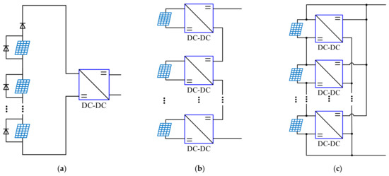
Figure 1.
Conventional configurations of a photovoltaic (PV) power generation system dealing with partially shading conditions. (a) String structure configuration; (b) distributed circuit configuration; (c) the hybrid structure.
Another solution to eliminate the partial shading effect on PV power generation systems is hardware methods, mainly used for the reconfiguration of connection schemes of PV modules. This method requires extra switches and involves a corresponding control algorithm [14,15]. One of the hardware solutions is string structure configuration, as presented in Figure 1a. The PV modules are connected in series to increase the output voltage and are connected to a DC bus through a DC/DC converter, and the MPPT of PV system is realized by the operation and control of the converter. Furthermore, to avoid the hot spots and potential damage to PV modules under a partial shadow condition, each PV module is connected paralleled with a diode so as to provide a bypass current path. However, this scheme cannot solve the problem of the MPPT control falling into the local optimum point, resulting in an efficiency reduction in PV power generation, and its efficiency is always lower than 90%. Moreover, this scheme needs a complex control method and increases the difficulty in application [16,17,18,19]. The distributed circuit configuration combined scheme provides another solution, as shown in Figure 1b. One DC/DC converter is set for each PV module, and the cascading multiple structures satisfies the voltage level requirement and can achieve a high efficiency of about 97%. However, the output power of each PV module flows entirely through the respective converter, leading to large current stress, power loss, and construction cost [20,21,22,23]. Combining these two solutions, the dual MPPT inverters with string modules are also widely applied, and the problems, including the output characteristic curve of the PV array with multiple peaks and an excessive loss of converter need to be considered simultaneously. For these solutions, many products have emerged on the market, such as module integrated converters and smart DC modules. The power optimizer P860/P960, produced by SolarEdge, is applied in PV systems in different structures with a superior efficiency, and the excessive loss of converters becomes the key factor that affects the efficiency of PV systems [24,25].
Moreover, a hybrid connect structure is also proposed. PV modules are connected in series to increase the voltage level, and each PV module is connected with a DC/DC converter connected in parallel to a DC bus, as shown in Figure 1c. In this scheme, the MPPT of each PV module is realized independently with the DC/DC converter, the same as for the smart DC module. However, the output current of the PV module does not only flow through converters, thus decreasing the power losses compared with the structure in Figure 1b. The DC/DC converter only needs to control the compensation current, and a high DC voltage level and efficiency of about 97% are achieved. However, the DC/DC converters are directly connected to the DC bus, causing high voltage stress [26,27,28,29,30]. Furthermore, the random variations in the partially shaded conditions may cause the fluctuation in output power of grid-connected PV power generation systems, reducing the reliability and power quality. Nowadays, the power fluctuations are stabilized mainly by energy storage (ES) systems, which are generally composed of several battery modules in series in order to meet the grid-connected voltage level. However, the central ES system with fixed series configuration suffers from the “barrel effect”, due to the characteristic differences among the battery modules, resulting in a reduction of the effective capacity, thus the additional active equalization or reconfigurable circuits are necessary [31,32,33].
To solve the above problems in the existing schemes, a novel cascaded modular PV/ES system is proposed for partial shading conditions. The circuit topology and control strategy of the PV/ES module are proposed to realize the MPPT control for an individual PV module, and an energy optimized strategy is designed to realize the constant active power from the PV/ES system to a grid in a certain time period, improving power conversion and transmission efficiency. Compared with the conventional PV power generation systems, the advantages of the proposed scheme are as follows: (1) Under the distributed structure of PV modules and ES modules, the current and voltage stresses of DC/DC converters can be significantly reduced; (2) each PV module is regulated by an ES module through the DC/DC converter, and the hot spots and hot strings phenomena can be avoided; and (3) the proposed energy optimization strategy for the coordination of all ES modules with their own capacity constraint, realizing the independent MPPT of each PV module and the constant active power between the PV/ES system and grid under the inconsistency of light intensity in partial shading conditions.
2. Topology, Operation Principle and Optimization Strategy of Proposed PV/ES System
2.1. Topology Configuration
The topology of the proposed cascaded modular PV/ES system is presented in Figure 2. Each PV/ES module consists of a PV module and a bidirectional DC/DC converter supplied by an ES module. The PV/ES modules are connected in series to satisfy the voltage level of DC bus, and the DC bus is connected to a power grid via a DC/AC converter. The control scheme of the proposed system is divided into two layers, including a converter control in the bottom layer and an energy management system (EMS) in the top layer. In the converter control layer, the bidirectional DC/DC converter is controlled in order to achieve the MPPT for an individual PV module and to compensate the current difference between the PV module and DC bus. As each PV module is regulated by an ES module through a DC/DC converter, the hot spots and hot strings phenomena can be avoided. The DC/AC converter controls the grid-connected power according to the reference value obtained by the EMS. In the EMS layer, the power reference is generated by the proposed energy optimization strategy according to the voltages and currents of the PV modules and the voltages and states of charge (SOC) of the ES modules.
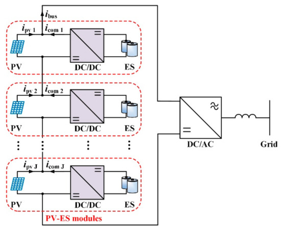
Figure 2.
The topology of proposed cascaded modular PV/energy storage (ES) system.
Compared with the conventional topology shown in Figure 1a, the multi-peak characteristic of the PV power curve in the proposed PV/ES system under partial shading conditions is eliminated, and all PV modules can operate at respective maximum power points. Compared with the conventional topology shown in Figure 1b, only a part of power from the PV module flows through the DC/DC converter in the proposed PV/ES system, reducing the power loss and construction costs. Compared with the conventional topology shown in Figure 1c, the DC/DC converters in the proposed PV/ES system are not directly connected to the DC bus, thus the voltage stresses of the power switches and devices can be greatly reduced.
2.2. Control Strategy of PV/ES Module
The topology and control strategy of an individual PV/ES module is presented in Figure 3. Each PV/ES module contains a PV module, an ES module, and a bidirectional DC/DC converter. As the PV/ES modules are connected in series, as shown in Figure 2, all the currents of the PV/ES modules are equal to the current of the DC bus. However, the currents of the PV modules, which depend on the respective light intensities, are different under partial shading conditions. The current differences between the PV modules and the DC bus can be compensated by the corresponding DC/DC converters as follows:
where ibus, ipv, and icom are the currents of DC bus, PV module, and converter, respectively; J is the number of modules; and the subscript j represents the j-th of the PV module.
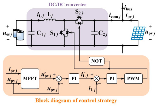
Figure 3.
Topology and control strategy of a PV/ES module.
As all of the PV/ES modules are connected in series, the voltage of the DC bus can be obtained as follows:
where ubus and upv are the voltages of DC bus and PV module, respectively.
According to Figure 3, the terminal voltage of the PV module is the same as the voltage of its parallel capacitor controlled by the DC/DC converter. The independent MPPT of each PV module can be achieved by controlling the output voltage of the corresponding DC/DC converter according to the respective light intensity. Therefore, in the proposed cascaded modular PV/ES system, all of the PV modules can operate at their own maximum power point, ensuring that the entire PV/ES system can obtain the maximum solar energy under partial shading conditions.
To realize the MPPT of an individual PV module, the control strategy of the bidirectional DC/DC converter is also designed, as shown in Figure 3, and the process of the MPPT algorithm based on the incremental conductance method is shown in Figure 4. The MPPT algorithm is adopted to generate the voltage reference value for the PV module according to its voltage and current. A double closed-loop control strategy is designed to control the voltage of the PV module so as to follow its reference value. The PI regulator of the outer loop generates the reference current of the inductance according to the deviation between the reference voltage and the actual voltage of the PV module. Furthermore, the PI regulator of the inner loop generates the duty ratio of the DC/DC converter according to the deviation between the reference current and the actual current of inductance.
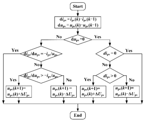
Figure 4.
Control process of the maximum power point tracking (MPPT) in the proposed PV/ES system.
2.3. Energy Optimization Strategy
From Figure 2, to realize the MPPT of the PV module, the ES module should provide energy to the PV module via a DC/DC converter, compensating the current difference between the PV module and the DC bus. However, because of the inconsistency of the light intensity under partial shading conditions, the currents of the PV modules are usually different, causing SOC differences among the ES modules. In addition, to realize the constant active power from the PV/ES system to the grid in a certain time period, the ES modules should be further used to compensate the power fluctuations caused by random variations of light intensity. Hence, an energy optimization strategy should be designed for the coordination of all of the ES modules under their own capacity constraints, realizing the independent MPPT of the PV modules and the constant grid-connected active power for the PV/ES system.
2.3.1. Energy Optimization Model
Defining SOCj(k) as the SOC of the j-th ES module at the starting time of the k-th optimization cycle [34] can be done as follows:
where ues is the voltage of the ES module, T is the time of one optimization cycle, and Ces is the capacity of ES module.
To increase the charging and discharging capacity margin of the ES module at the beginning of the next optimization cycle, the objective function is designed to make the SOCs of all ES modules converge to 50%. Hence, the target function is firstly designed as follows:
To prevent the ES module from deep charging and discharging, which will shorten the working life of the ES module, the upper and lower limits of SOC are set as 80% and 20%, respectively. Hence, the penalty function can be defined as follows:
Combining the target function (4) and penalty function (5), the final objective functions of the energy optimization model can be obtained as follows:
where b is the penalty factor for deep charging and discharging. Assuming b is large enough, in the process of searching for the minimum fitness value of the target function (6), the optimization algorithm will automatically avoid deep charging and discharging the ES modules.
To limit the current of the DC bus within the safety operating range, and to avoid reverse current, the constraint can be defined as follows:
2.3.2. Energy Optimization Strategy Based on PSO Algorithm
As one of the most common optimization algorithms, the PSO algorithm has the advantages of easy implementation, fast convergence, and ideal robustness, and it has been successfully applied to the cooperative planning of renewable power sources and energy storage systems [35].
In terms of the above energy optimization model, an energy optimization strategy based on the PSO algorithm is proposed in order to optimize the current of the DC bus in the cascaded modular PV/ES system. The implementation steps of the proposed algorithm are shown in Figure 5.
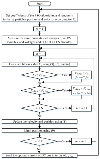
Figure 5.
Implementation flowchart of the proposed energy optimization strategy.
- (1)
- Definitions: The current of the DC bus is defined as the particle position, i.e., x = ibus, and the target function (6) is selected as the fitness value evaluation function.
- (2)
- Initialization: Set the number of particles N, number of iterations M, the penalty factor b, the weight coefficients w, c1, and c2. Randomly initialize the position and velocity of each particle in a range, which is given as (7). Set the initial iterative algebra as m = 1.
- (3)
- Fitness value calculation: considering the position, measured real-time currents, voltages of all PV modules, and voltages and SOC of all ES modules, the fitness value of each particle is calculated using Equations (3), (5) and (6).
- (4)
- The best fitness values and positions updating: the latest fitness value of the n-th particle (n = 1, 2, …, N) is compared with its individual best fitness value, and the smaller one and its corresponding position will be recorded as the new individual best fitness value and best position, which are denoted as FnBest and pnBest, respectively. Then, all of the new individual best fitness values are compared with the previous global best fitness value, and the minimum fitness value and its corresponding position will be selected to update the global best fitness value and global best position, which are denoted as FgBest and pgBest, respectively.
- (5)
- Particles updating: The velocities and positions of all of the particles are updated using the following [36]:where n and m represent the n-th particle and m-th iteration, respectively; v and x represent the velocity and position of particles, respectively; w, c1, and c2 are weight coefficients; and r1 and r2 are randomly generated in [0, 1].
- (6)
- Constraint judgment: if the particle position exceeds the range given in (7), it should be replaced by the following:
- (7)
- End of the iteration: If the iterative algebra m is smaller than M, set m = m + 1 and return to step 3. If m is equal to M, the iteration will be stopped, and the optimal current of the DC bus is achieved according to the global best position, as follows:
Finally, the reference value of the active power from the PV/ES system to the grid is calculated as follows:
2.3.3. Control Scheme of Grid-Connected DC/AC Converted
Figure 6 shows the control scheme of the grid-connected DC/AC converter. From the figure, a virtual synchronous generator (VSG) controller in [37] is introduced to control the active and reactive power. The reference value of the active power for the VSG controller is generated at the beginning of the optimization cycle, and remains constant throughout the cycle, realizing the constant grid-connected active power of PV/ES system in a certain time period. To ensure that all of the ES modules have a sufficient charging and discharging margin in each cycle, the energy optimization strategy generates a reference value of the active power according to the currents and voltages of all PV modules and the voltages and SOC of all ES modules.
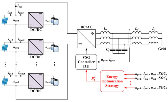
Figure 6.
Block diagram of the control scheme using the proposed energy optimization strategy.
3. Experimental Verification
The hardware-in-loop (HIL) experimental platform based on the OPAL-RT OP5600 developed to verify the effectiveness of the proposed topology and control strategy is presented in Figure 7. A KEYSIGHT DSO9104A oscilloscope is used to record the experimental results. A PV/ES system composed of four PV/ES modules is established according to the topology and control structure shown in Figure 6, and its parameters are presented in Table 1. Furthermore, the light intensities of the four PV modules, which are different in order to emulate the partial shading conditions caused by the slow movement of clouds, are presented in Figure 8.
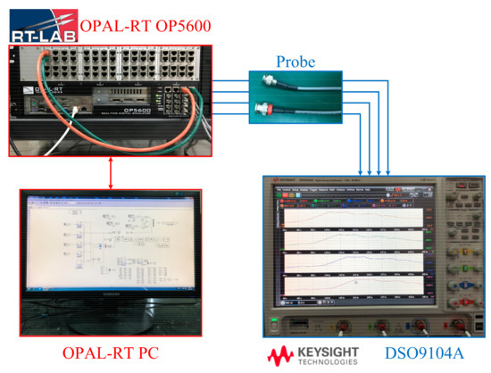
Figure 7.
Hardware-in-loop (HIL) experimental platform.

Table 1.
Parameters of the PV/ES system and control strategy.
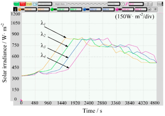
Figure 8.
Light intensity of four PV modules.
Figure 9a–d shows the experimental powers of the PV modules, the compensation currents of the DC/DC converters, and the SOCs of the ES modules in four PV/ES modules in the proposed system, separately. PMPP1, PMPP2, PMPP3, and PMPP4 are the theoretical maximum powers of the individual PV modules at their own maximum power points, depending on their light intensity, respectively. Ppv1, Ppv2, Ppv3, and Ppv4 are the actual powers generated by the four PV modules, respectively. According to the figures, all of the powers generated by the PV modules are very close to the theoretical maximum values. Therefore, the topology and control strategy of the PV/ES module effectively realizes the independent MPPT control for each PV module, ensuring the PV/ES system can obtain a maximum solar energy under partial shading conditions.
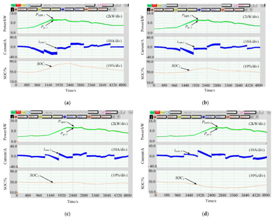
Figure 9.
PV power, compensation current, and SOC in the PV/ES modules: (a) PV/ES module 1, (b) PV/ES module 2, (c) PV/ES module 3, (d) PV/ES module 4.
From Figure 9a–d, icom1, icom2, icom3, and icom4 are the compensation currents generated by the DC/DC converters in the four PV/ES modules, respectively, which compensate for the current difference between the individual PV module and DC bus. As the current of the DC bus is the same for all of the modules, there is an inverse relationship between the light intensity and the compensation current, i.e., the PV module with a lower light intensity should be compensated by a larger current than the ones with a higher light intensity. For example, at 1440 s, the light intensity decreases one by one from the first PV module to the fourth PV module, while the corresponding compensation current for each PV module increases sequentially, which is approximately −20 A, −10 A, 0, and +6 A, respectively. Considering the case at 3840 s as another example, the light intensity gradually increases from the first PV module to the fourth PV module, while the compensation current in the corresponding modules decreases from positive to negative. According to the current direction defined in Figure 3 and Figure 6, the positive compensation current represents that the ES module is discharging, and the negative compensation current represents that the ES module is charging.
The SOCs of the ES modules are also presented in Figure 9a–d, as SOC1, SOC2, SOC3, and SOC4. According to Figure 9a, when the compensation current is negative, the SOC is rising as the ES module is charging; when the compensation current is positive, the SOC is declining and the ES module is discharging. Furthermore, this relationship between the compensation current and SOC can also be found and verified in other ES modules, as shown in Figure 9b–d. Therefore, it can be seen that the SOCs of all ES modules are maintained within the range of 20% and 80%, which means that all of the ES modules are prevented from deep charging and discharging. In addition, the SOCs of all of the ES modules obtain convergence trends toward 50%, which is consistent with the control purpose of the energy optimization strategy. Moreover, the proposed PV/ES system achieves efficiency at about 97% under a partial shading condition, which is higher than the conventional string structure PV system with an efficiency of 90% [19], and is similar to the distributed and hybrid structure PV systems with an efficiency of about 97% [20,24], providing an effective and practical solution for power generation system.
Figure 10 shows the current of the DC bus and the power of the PV/ES system. The iopt is the optimal current of the DC bus searched out by the PSO algorithm, which is the global best position given in (10), while the ibus is the actual current of the DC bus. It can be seen that the current of the DC bus follows its optimal values. In Figure 10, the Ppvsum is the sum of the power generated by all of the PV modules in the PV/ES system, while Pgrid is the active power of the grid-connected converter, i.e., the active power from the PV/ES system to the grid. According to Figure 10, although Ppvsum varies with the light intensity, the active power from the PV/ES system to the grid is constant in the given time period.
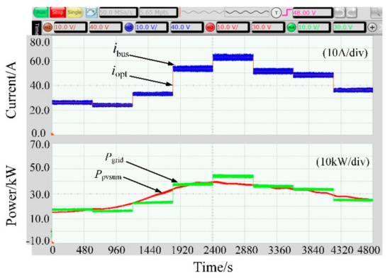
Figure 10.
Current of the DC bus and the power of the PV/ES system.
4. Conclusions
This paper proposes a novel cascaded modular PV/ES system for MPPT and power smoothing under partial shading conditions. In the proposed topology, the adverse effects of the local shadow on the PV system can be eliminated, and all of the PV modules can operate at their individual maximum power points. Moreover, the “barrel effect” reducing the effective capacity of ES system is also alleviated, as the ES modules only need to meet the voltage level of the PV modules, but not the grid-connected voltage level. Compared with conventional photovoltaic systems, the proposed scheme can avoid hot spots and hot strings phenomena for the PV module and the large current and voltage stresses for DC/DC converters. Moreover, an energy optimization strategy based on the PSO algorithm is proposed for the coordination of the distributed ES modules, avoiding deep charging and discharging of all ES modules, with the convergence of their SOCs toward 50%. The proposed energy optimization strategy also realizes the constant active power from the PV/ES system to the grid under inconsistency of light intensity in partial shading conditions, improving the power conversion and transmission efficiency. Moreover, the proposed system achieves efficiency at about 97% under partial shading conditions, which is higher than the conventional string structure PV system with an efficiency of 90%, and is similar to the distributed and hybrid structure PV systems with an efficiency of about 97%, providing an effective and practical solution for power generation systems. In addition, the high frequency and compact topology design scheme of the DC/DC converters and the control scheme adapts to the randomness and volatility of the photovoltaic and energy storage systems for the PV/ES system can be considered as directions for future research and for the improvement of the PV/ES system.
Author Contributions
Conceptualization, Y.F. and L.F.; methodology, H.W. and Y.W.; software, Z.W.; validation, Y.F., Z.W., and Y.W.; formal analysis, B.L.; investigation, J.H.; resources, J.H. and S.L.; writing—original draft preparation, Y.W.; writing—review and editing, Y.F., Z.W., and Y.W.; visualization, J.H. and S.L.; supervision, Y.W.; project administration, H.W. and Y.F.; funding acquisition, Y.F. All authors have read and agreed to the published version of the manuscript.
Funding
This research was funded by the Science and Technology Project of State Grid Corporation of China under grant no. 521304190072 and the Industrial Guidance Key Project of Fujian Province under grant no. 2020H0043.
Institutional Review Board Statement
Not applicable.
Informed Consent Statement
Not applicable.
Data Availability Statement
Not applicable.
Conflicts of Interest
The authors declare that they have no known conflict of interest.
References
- Malinowski, M.; Leon, J.I.; Abu-Rub, H. Solar Photovoltaic and Thermal Energy Systems: Current Technology and Future Trends. Proc. IEEE 2017, 105, 2132–2146. [Google Scholar] [CrossRef]
- Li, W.; Zhang, G.; Pan, T.; Zhang, Z.; Geng, Y.; Wang, J. A Lipschitz Optimization-Based MPPT Algorithm for Photovoltaic System under Partial Shading Condition. IEEE Access 2019, 7, 126323–126333. [Google Scholar] [CrossRef]
- Lashab, A.; Sera, D.; Guerrero, J.M.; Mathe, L.; Bouzid, A. Discrete Model-Predictive-Control-Based Maximum Power Point Tracking for PV Systems: Overview and Evaluation. IEEE Trans. Power Electron. 2017, 33, 7273–7287. [Google Scholar] [CrossRef]
- Zhao, Z.; Cheng, R.; Yan, B.; Zhang, J.; Zhang, Z.; Zhang, M.; Lai, L.L. A dynamic particles MPPT method for photovoltaic systems under partial shading conditions. Energy Convers. Manag. 2020, 220, 113070. [Google Scholar] [CrossRef]
- El-Helw, H.M.; Magdy, A.; Marei, M.I. A hybrid maximum power point tracking technique for partially shaded photovoltaic arrays. IEEE Access 2017, 5, 11900–11908. [Google Scholar] [CrossRef]
- Sharma, P.; Agarwal, V. Exact Maximum Power Point Tracking of Grid-Connected Partially Shaded PV Source Using Current Compensation Concept. IEEE Trans. Power Electron. 2014, 29, 4684–4692. [Google Scholar] [CrossRef]
- Hu, K.; Li, W.; Wang, L.; Zhu, F.; Shou, Z. Topology and control strategy of power optimisation for photovoltaic arrays and inverters during partial shading. IET Power Electron. 2018, 12, 62–71. [Google Scholar] [CrossRef]
- Goud, J.S.; Kalpana, R.; Singh, B.; Kumar, S.; Goud, S.; Kalpana, R. A Global Maximum Power Point Tracking Technique of Partially Shaded Photovoltaic Systems for Constant Voltage Applications. IEEE Trans. Sustain. Energy 2018, 10, 1950–1959. [Google Scholar] [CrossRef]
- Xu, S.; Gao, Y.; Zhou, G.; Mao, G. A Global Maximum Power Point Tracking Algorithm for Photovoltaic Systems Under Partially Shaded Conditions Using Modified Maximum Power Trapezium Method. IEEE Trans. Ind. Electron. 2021, 68, 370–380. [Google Scholar] [CrossRef]
- Teshome, D.F.; Lee, C.H.; Lin, Y.W.; Lian, K.L. A Modified Firefly Algorithm for Photovoltaic Maximum Power Point Tracking Control under Partial Shading. IEEE J. Emerg. Sel. Top. Power Electron. 2016, 5, 661–671. [Google Scholar] [CrossRef]
- Lyden, S.; Haque, M.E. A simulated annealing global maximum power point tracking approach for PV modules under partial shading conditions. IEEE Trans. Power Electron. 2016, 31, 4171–4181. [Google Scholar] [CrossRef]
- Khateb, A.E.; Rahim, N.A.; Selvaraj, J.; Uddin, M.N. Fuzzy-logic-controller-based sepic converter for maximum power point tracking. IEEE Trans. Ind. Appl. 2014, 50, 2349–2358. [Google Scholar] [CrossRef]
- Sen, T.; Pragallapati, N.; Agarwal, V.; Kumar, R. Global maximum power point tracking of PV arrays under partial shading conditions using a modified particle velocity-based PSO technique. IET Renew. Power Gener. 2018, 12, 555–564. [Google Scholar] [CrossRef]
- Zhang, W.; Zhou, G.; Ni, H.; Sun, Y. A Modified Hybrid Maximum Power Point Tracking Method for Photovoltaic Arrays Under Partially Shading Condition. IEEE Access 2019, 7, 160091–160100. [Google Scholar] [CrossRef]
- Rong, F.; Gong, X.; Huang, S. A Novel Grid-Connected PV System Based on MMC to Get the Maximum Power Under Partial Shading Conditions. IEEE Trans. Power Electron. 2017, 32, 4320–4333. [Google Scholar] [CrossRef]
- Seyedmahmoudian, M.; Rahmani, R.; Mekhilef, S.; Oo, A.M.T.; Stojcevski, A.; Soon, T.K.; Ghandhari, A.S. Simulation and Hardware Implementation of New Maximum Power Point Tracking Technique for Partially Shaded PV System Using Hybrid DEPSO Method. IEEE Trans. Sustain. Energy 2015, 6, 850–862. [Google Scholar] [CrossRef]
- Uno, M.; Kukita, A. Single-Switch Voltage Equalizer Using Multistacked Buck–Boost Converters for Partially Shaded Photovoltaic Modules. IEEE Trans. Power Electron. 2014, 30, 3091–3105. [Google Scholar] [CrossRef]
- Lavado Villa, L.F.; Raison, B.; Crebier, J.C. Toward the design of control algorithms for a photovoltaic equalizer: Detecting shadows through direct current sampling. IEEE J. Emerg. Select Top. Power Electron. 2014, 2, 893–906. [Google Scholar] [CrossRef]
- Mao, M.; Cui, L.; Zhang, Q.; Guo, K.; Zhou, L.; Huang, H. Classification and summarization of solar photovoltaic MPPT techniques: A review based on traditional and intelligent control strategies. Energy Rep. 2020, 6, 1312–1327. [Google Scholar] [CrossRef]
- Bratcu, A.I.; Munteanu, I.; Bacha, S.; Picault, D.; Raison, B. Cascaded DC-DC converter photovoltaic systems: Power optimization issues. IEEE Trans. Ind. Electron. 2011, 58, 403–511. [Google Scholar] [CrossRef]
- Vighetti, S.; Ferrieux, J.-P.; Lembeye, Y. Optimization and Design of a Cascaded DC/DC Converter Devoted to Grid-Connected Photovoltaic Systems. IEEE Trans. Power Electron. 2012, 27, 2018–2027. [Google Scholar] [CrossRef]
- Kadri, R.; Gaubert, J.-P.; Champenois, G. Nondissipative String Current Diverter for Solving the Cascaded DC–DC Converter Connection Problem in Photovoltaic Power Generation System. IEEE Trans. Power Electron. 2012, 27, 1249–1258. [Google Scholar] [CrossRef]
- Mathi, D.K.; Chinthamalla, R. Enhanced leader adaptive velocity particle swarm optimisation based global maximum power point tracking technique for a PV string under partially shaded conditions. IET Renew. Power Gener. 2020, 14, 243–253. [Google Scholar] [CrossRef]
- Energy Output Comparison, Module Mismatch, Ouddorp, The Netherlands. Available online: https://www.solaredge.com/sites/default/files/solaredge-comparative-case-study-ouddorp-nl.pdf (accessed on 5 June 2021).
- Special Benefits Based on SMART DC Module. Available online: https://krannich-solar.com/fileadmin/content/pdf/Germany/Suntech_2018/Smart_DC_Module_english.pdf (accessed on 5 June 2021).
- Kumar, N.; Hussain, I.; Singh, B.; Panigrahi, B.K. MPPT in Dynamic Condition of Partially Shaded PV System by Using WODE Technique. IEEE Trans. Sustain. Energy 2017, 8, 1204–1214. [Google Scholar] [CrossRef]
- Obukhov, S.; Ibrahim, A.; Diab, A.A.Z.; Al-Sumaiti, A.S.; Aboelsaud, R. Optimal Performance of Dynamic Particle Swarm Optimization Based Maximum Power Trackers for Stand-Alone PV System Under Partial Shading Conditions. IEEE Access 2020, 8, 20770–20785. [Google Scholar] [CrossRef]
- Kumar, N.; Hussain, I.; Singh, B.; Panigrahi, B.K. Single sensor based MPPT for partially shaded solar photovoltaic by using human psychology optimisation algorithm. IET Gener. Transm. Distrib. 2017, 11, 2562–2574. [Google Scholar] [CrossRef]
- Elserougi, A.A.; Diab, M.S.; Massoud, A.M.; Abdel-Khalik, A.S.; Ahmed, S. A Switched PV Approach for Extracted Maximum Power Enhancement of PV Arrays during Partial Shading. IEEE Trans. Sustain. Energy 2015, 6, 767–772. [Google Scholar] [CrossRef]
- Power Optimizer. Available online: https://www.solaredge.com/us/products/power-optimizer#/ (accessed on 5 June 2021).
- Chen, S.-Z.; Wang, Y.; Zhang, G.; Chang, L.; Zhang, Y. A Sneak Circuit Theory Based Approach to Avoiding Short-circuit Paths in Reconfigurable Battery Systems. IEEE Trans. Ind. Electron. 2020. [Google Scholar] [CrossRef]
- Shang, Y.; Zhu, C.; Fu, Y.; Mi, C.C. An Integrated Heater Equalizer for Lithium-Ion Batteries of Electric Vehicles. IEEE Trans. Ind. Electron. 2019, 66, 4398–4405. [Google Scholar] [CrossRef]
- He, L.; Yang, Z.; Gu, Y.; Liu, C.; He, T.; Shin, K.G. Soh-aware reconfiguration in battery packs. IEEE Trans. Smart Grid 2018, 9, 3727–3735. [Google Scholar] [CrossRef]
- Zhao, Z.; Guo, J.; Lai, C.S.; Xiao, H.; Zhou, K.; Lai, L.L. Distributed model predictive control strategy for islands multi-microgrids based on noncooperative game. IEEE Trans. Ind. Inform. 2021, 17, 3803–3814. [Google Scholar] [CrossRef]
- Li, R.; Wang, W.; Xia, M. Cooperative Planning of Active Distribution System With Renewable Energy Sources and Energy Storage Systems. IEEE Access 2017, 6, 5916–5926. [Google Scholar] [CrossRef]
- Chen, S.-Z.; Xiong, G.; Zhang, G.; Yu, S.S.; Iu, H.H.-C.; Fernando, T.; Zhang, Y.; Iu, H.-C. An Aerodynamics-Based Novel Optimal Power Extraction Strategy for Offshore Wind Farms with Central VSCs. IEEE Access 2018, 6, 44351–44361. [Google Scholar] [CrossRef]
- Wu, H.; Ruan, X.; Yang, D.; Chen, X.; Zhao, W.; Lv, Z.; Zhong, Q.-C. Small-Signal Modeling and Parameters Design for Virtual Synchronous Generators. IEEE Trans. Ind. Electron. 2016, 63, 4292–4303. [Google Scholar] [CrossRef]
Publisher’s Note: MDPI stays neutral with regard to jurisdictional claims in published maps and institutional affiliations. |
© 2021 by the authors. Licensee MDPI, Basel, Switzerland. This article is an open access article distributed under the terms and conditions of the Creative Commons Attribution (CC BY) license (https://creativecommons.org/licenses/by/4.0/).