1. Introduction—Significance of the Problem
The transport of the winning in non-ferrous metal ore mines, using a room and pillar mining system, is most often conducted using bucket loaders and haul trucks. The permissible levels of pollutant emissions in the exhaust gases for this type of transport modes are specified in the Stage standards, for the engines used in new non-road mobile machinery (NRMM). These standards have been structured as progressively more stringent levels from Stage I to V. From Stage V, Regulation (EU) 2016/1628 of the European Parliament and of the Council [
1] lays down emission requirements for all categories of diesel and spark ignition non-road mobile engines, the applicability of HC+NO
x and particulate matter (PM) emission levels. Details are presented in
Table 1.
Although the standard currently in force in Europe is Stage V, the loaders and haul trucks used to transport the winning in non-ferrous ore mines often scarcely meet Stage II or IIIA exhaust emission standards, introduced ten or more years earlier. Why is this happening and what is the reason for that? The situation may be explained by the fact that the economically justified life cycle of a loader or a haulage truck in deep mines is usually six to eight years. It might be surprising that it is still possible to buy from manufacturers loaders and haul trucks meeting barely Stage II and IIIA standards, which can be easily determined when analyzing the available catalogues of currently offered mining machines [
2]. At the same time, some manufacturers provide mining machines that meet the newer exhaust emission standards [
3]. Long transition periods and the principles of operation on the market of previously approved structures come to the assistance of mining machinery manufacturers. There are also manufacturers of mining machinery who do not provide information on what emission standards their machines meet [
4], apparently considering this parameter to be irrelevant for their potential customers.
In the era of attempts to stop rapid climate change, it is crucial to choose the transport modes for the winning in deep mines both in terms of efficiency and cost-effectiveness as well as considering their environmental aspect. As an environmental aspect, it is proposed to use the permissible level of pollutant content in the exhaust gases from the engines of loaders and haul trucks, determined under the Stage standards as the sum of hydrocarbons and nitrogen oxides (HC+NOx) masses or the mass of particulate matter (PM).
There is a need to develop a multi-criteria method supporting the decision-making process on the type of transport mode to choose for transporting the winning in the room and pillar mining systems. Taking into account the environmental aspect, the method should reward loaders and haul trucks that comply with more stringent emission standards.
2. Modeling of Logistic Systems in the Field of Mining
The problem of providing the necessary resources for the flow of cargo in logistics systems is widely described in the available literature. For the selection of variants of different solutions in logistics systems, multi-criteria assessment methods are applied; they use unit costs for this purpose but can also include various technical and operational or ergonomic criteria. Experiments and computer simulations concerning supply chains are carried out [
5], and also in the context of gradually implementing potential economic, social and environmental factors for development of sustainable products [
6]. However, classical optimization methods focus on one criterion for evaluating solution variants. The selection of transport modes with a limited capacity based on one optimization criterion [
7] is possible for the specified transport tasks. The very potential of the logistics system can also be optimized [
8]. In order to assess the potential, it is necessary to take into account the dynamics of logistics processes and their stochastic nature [
9,
10]. One of the important steps in the optimization process is the sufficiently detailed identification of cost drivers in the supply chain area [
11] when costs are used as an evaluation criterion [
12].
The transport of the winning during the exploitation of a mining field is one example of a logistics problem. Methods of multi-criteria evaluation of logistics systems and their optimization could also be used in the mining industry, after necessary modifications.
On the other hand, the first computational and simulation models encountered in mining are most commonly the examples of queuing theory, such as models of haul trucks transporting the winning movement. E. Koenigsberg was one of the first to solve the problem of determining the production for a fixed number of crews working on several walls in an underground coal mine. The mathematical solution was compared with the actual results obtained in coal mines in Illinois [
13,
14].
The next step in development was the use of software languages for building computer simulation models. P. Harvey developed a model of rail transport and used the GPSS programing language for simulation [
14,
15,
16]. The case was taken from an underground molybdenum ore mine. The simulation model was used to determine the optimal number of trainsets to transport a given amount of the winning to the crusher. The loaded trains had to queued for unloading and to wait for an empty single track and for the crusher area to be free. The construction of simulation models of belt conveyors in underground coal mines was a particular challenge. R. Sanford seems to be the first to tackle this problem, using Fortran language to simulate the operation of a belt conveyor system [
17,
18].
S. Suboleski and J. Lucas developed a program in Fortran language that simulated mining operations for room and pillar systems [
14,
19]. T. O’Neil and C. Manula applied the simulation model to handle the transport of the winning in the opencast mine [
20]. Another example of the first simulation models was the model of transport processes in an opencast copper ore mine. It described the operations of loading the mining product onto the haul trucks with the use of five loaders. The winning was first dumped into an ore crusher and then onto a waste pile or a leaching area. Based on the simulation model, it was determined how the dispatcher should direct the haul trucks to different loaders to minimize the queuing time. The results of the model written in Fortran language showed that the decisions made on its basis would significantly improve the loading process [
21].
In the following years, the number of works based on simulation models, built using various simulation languages and commercial software in the field of mining, increased rapidly.
3. Description of Mining Processes in Copper Ore Mines According to Business Process Model and Notation (BPMN)
The room and pillar mining system, used in underground mines of non-ferrous ores, is adapted to the geological and mining characteristics of the deposit, in particular its thickness. The exploitation of the non-ferrous metal ore deposits with a thickness of up to 5 m is carried out with the use of explosives. For this purpose, the exploitation field is cut with rooms and drifts with the separation of protective pillars—this is the cross-cutting stage. The cross-cutting of the field leaves protective pillars, the task of which is to protect the ceiling. The shorter dimension of the protective pillar is most often located perpendicularly to the works site. As the front progresses, the pillars from the last rows in front of the extraction line are cut into smaller ones, minimizing the losses of the winning from the exploited field—this is the retreating stage. The size of the residual pillars depends on the local geological and mining conditions as they should provide appropriate stable support for the ceiling in the area of the liquidated field. Over time, the ceiling gradually settles on the remaining pillars, closing the exploited space.
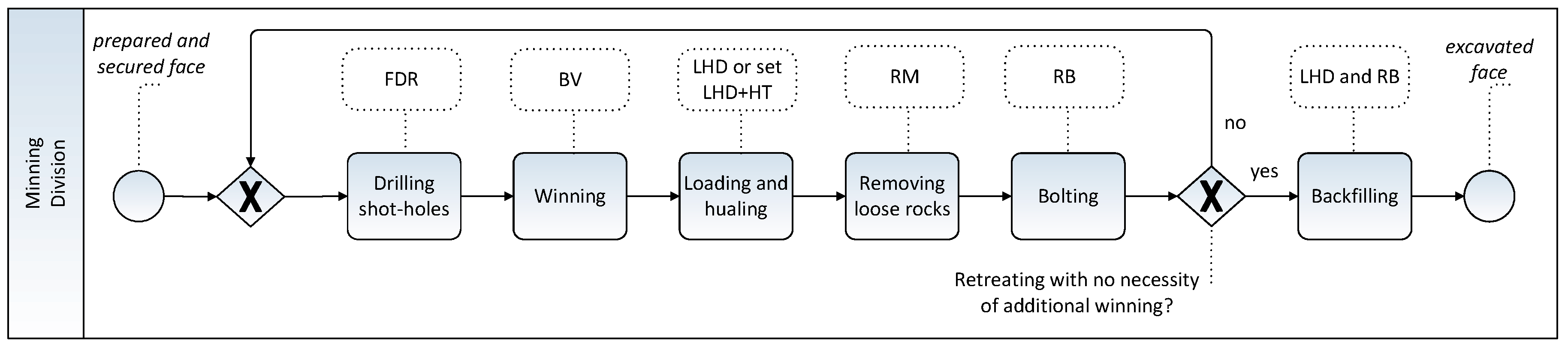
After blasting the mine face, the mining product is extracted with the use of production loaders (LHD), which load it onto haul trucks (HT) or transport it directly to the dumping point built on a belt conveyor. Then, the excavated material is transported by a network of belt conveyors to the main retention reservoirs at the mining shafts. In the mining system using explosives, technological tasks are carried out in a closed cycle of technological operations (
Figure 1):
Figure 1.
Copper ore mining process recorded in business process model and notation (BPMN) [
22].
Figure 1.
Copper ore mining process recorded in business process model and notation (BPMN) [
22].
After the last step of the cycle, the whole process in the mine face starts over. It would not be possible without carrying out several auxiliary operations on an ongoing basis.
In deep mines, using explosives for the extraction, mining technologies are based on the use of mobile mining machines on wheeled chassis. In the implementation of mining processes, self-propelled machines of various construction are used for the following groups of works:
Mining of the deposit, i.e., drilling trucks (FDR) and blasting vehicles (BV);
Securing and liquidating mining excavations, i.e., bolting rig (RB) or rock ripping machine (RM);
Loading and transport of excavated material, i.e., bucket loaders (LHD) and haul trucks of various sizes (HT);
Transport of personnel, materials, devices and machines as well as tools (including transport, fuel and lubrication vehicles);
Preparation of transport roads and auxiliary works (including bulldozers, drainage trucks).
A preliminary analysis of the costs of the winning haulage process from the site indicates that a significant cost of the process is associated with the mining product transport, called tire haulage. The selection of a machine set (direct haulage with a loader or a set of a loader and haul trucks), in relation to the amount of the product hauled per shift and the distance to dumping points is crucial for the cost optimization of this process [
23].
4. Selection of Transport Modes according to the Economic Efficiency Criteria
The method of selecting the transport modes proposed in the book [
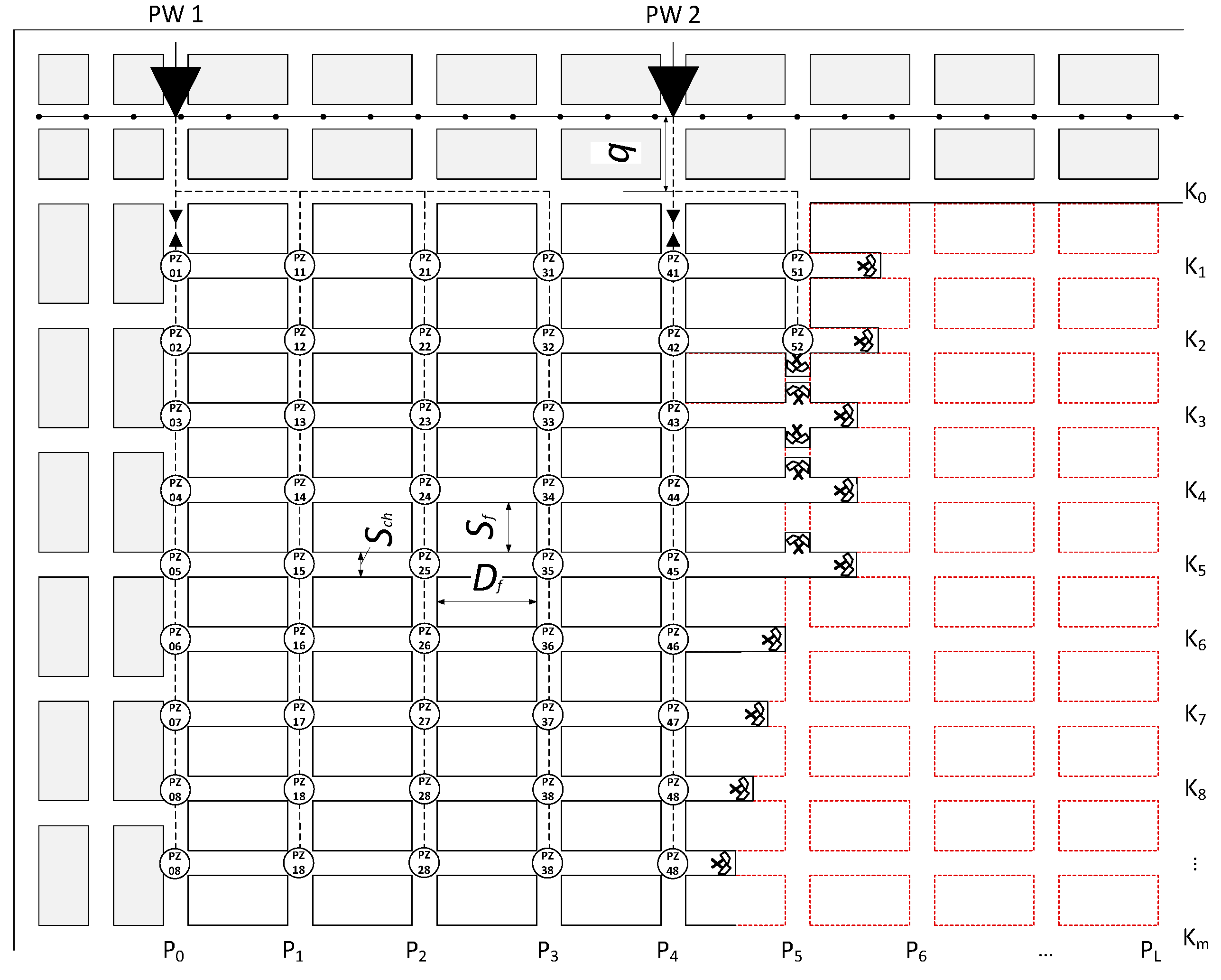
24] is based on the observation that the distance to be covered by the means of transport when transporting the excavated material for the
cross-cutting stage can be described as the product of the distance between the loading and unloading points for individual mine faces multiplied by the number of journeys to be made to haul the material out of the blasted mine faces. Importantly, the duration of this task in the non-ferrous metal ore mine is limited to the duration of one shift since the primary goal is to ensure an appropriate output level. The distance between the dumping point and the loading point of the material
dij located at the earlier intersection of the crosscut and the corridor (which results from the technology of loading the winning between the loader and haul trucks) can be expressed by the following Formula [
24]:
where
Sf—width of the technological pillar [m],
Df—length of the technological pillar [m],
Sch—width of the drift [m],
i—number of corridors, and
j—number of crosscuts. By
q the distance [m] between the discharge point and the beginning of the exploitation field is marked, resulting from the fact that the field of exploitation is contoured with a bundle of drifts in which the belt conveyor is placed.
The places of loading points, conventionally marked as PZ, are shown in
Figure 3, which includes a fragment of the exploitation field.
It was taken into account that the point of loading the winning is always at the closest intersection of the corridor and the crosscut as space is needed for the loader to manoeuvre while collecting the product into the bucket (the product is scattered after the wall blasting) and for loading onto the haul truck. The loader cannot turn around in a tight excavation; to load HT the LHD loader must reverse to the nearest intersection. In the case of the winning haulage with the use of loaders only, minor movements of the loader while scooping the material onto a bucket have been omitted. Hence, both cases—the haulage of the output with the use of loaders and the sets of a loader plus haul trucks—have been described in a standardized manner. Then, using
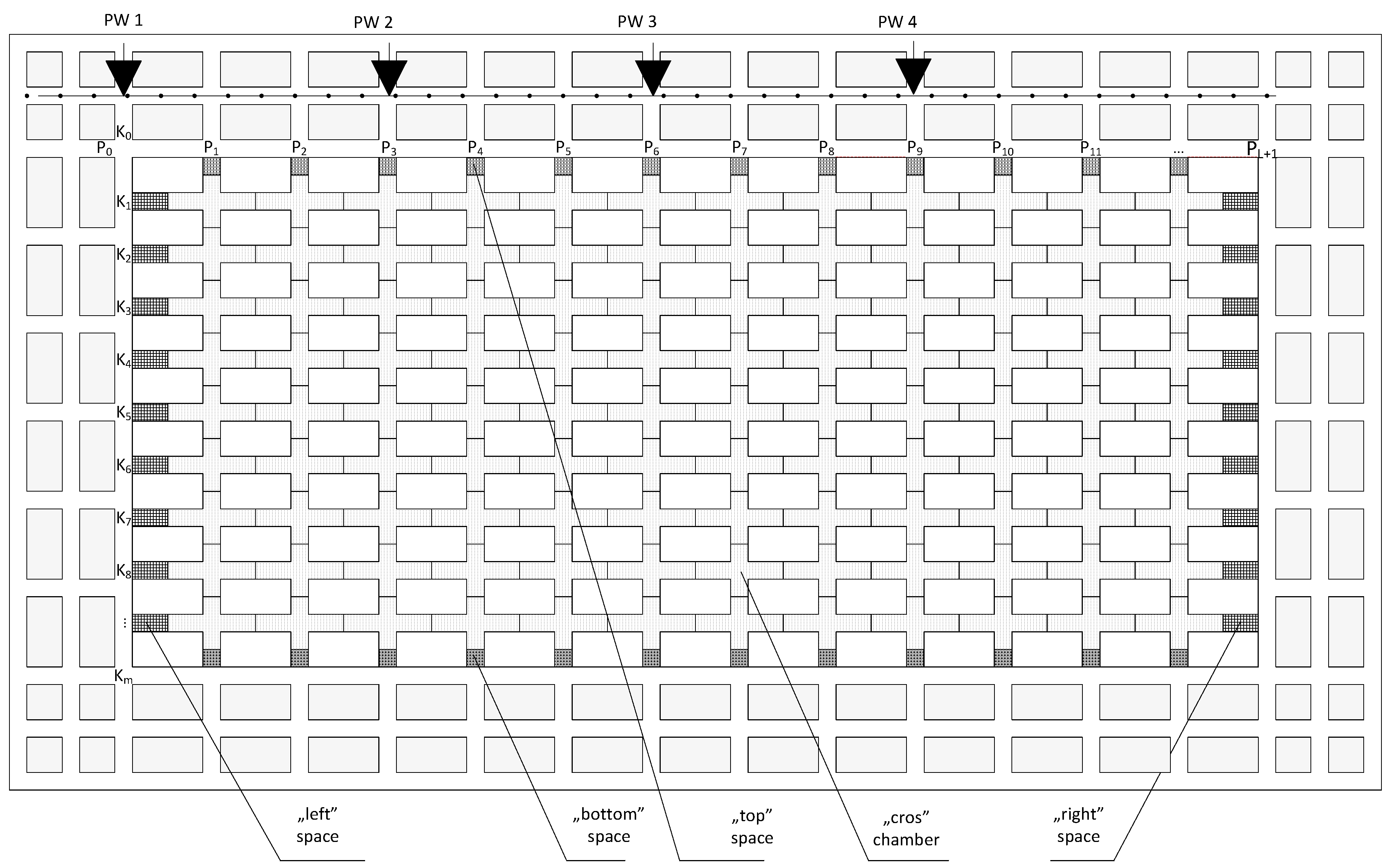
n,
ng,
nd,
nl,
np the number of journeys for the winning and with it, between the discharge point PW and the loading point PZ, from individual types of chambers have been marked. For the calculation of the volume of the excavation sites made during the cross-cutting stage, for the entire field of exploitation, chambers in the shape of a “cross” were proposed. Additionally, it turned out to be necessary to describe the space remaining at the boundaries of the field with the following nomenclature: “bottom” and “top”, “left” and “right”. In addition, these spaces are characterized by the common name “the remainder”. The proposed shapes of chambers and additional spaces, when summed up, make it possible to describe the total volume of workings at the cross-cutting stage, which was the main idea of such a division, details are shown in
Figure 4.
The number of journeys of the transport means depends on the volume of the product that can be obtained from a single area of a given type and the volume of the winning that can be transported at one time. The discharge points are opened in synchronisation with the movement of the front line of the crosscut.
The construction of discharge points located above the belt conveyors is associated with incurring certain costs by deep mines. Most often, deep mines try to build and activate the mentioned discharge points at the last possible moment: when the workings line reaches the planned location of the discharge point. Earlier construction of the discharge points for the entire field of exploitation means a capital freeze for up to two or three years, depending on the pace of exploitation and the size of the field. Currently, the most commonly used strategy is to launch successive discharge points on a par with the cross-cutting line.
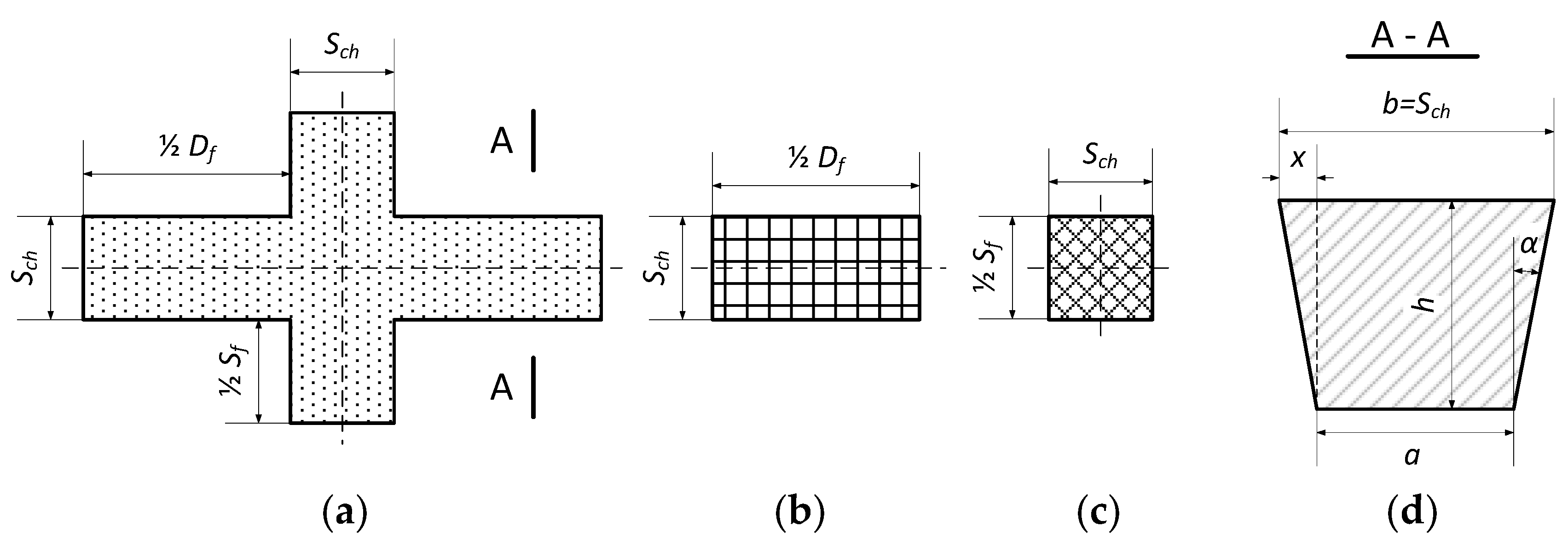
Based on the dimensions and shapes of the rooms, it is possible to establish their volume, and thus the mass of the excavated material, and then determine the number of transport journeys necessary to haul the excavated material with the selected means of transport. Details are shown in
Figure 5. In the cross-section, the drifts and crosscuts have the shape of an inverted trapezoid; at the stage of designing the exploitation method of the deposit, its characteristic dimensions are known:
h—thickness of the exploitation gangway and angle
α—the slope of the sidewall (the sidewall of the mining excavation in the useful mineral or possibly in the gangue), most often α = 10°.
The number of journeys
n of the transport mode, taking into account the fact that all the winning obtained from the area must be transported (the number of journeys is, therefore, a whole number, obtained after rounding up) and the specific volume
VŚrT that can be taken by the transport mode at one time, for the “cross” chamber is:
and for other spaces [
24]:
At this point, all the components that allow the calculation of the distance to be covered by the means of transport during the winning haulage for the cross-cutting stage are already determined; based on the aforementioned product of the distance dij to be covered between the loading and unloading points for individual mine faces according to Formula (1) and the number of journeys n according to Formula (2) (or the number of journeys ng and nd according to Formula (3) and the number of journeys nl and np according to Formula (4)).
The
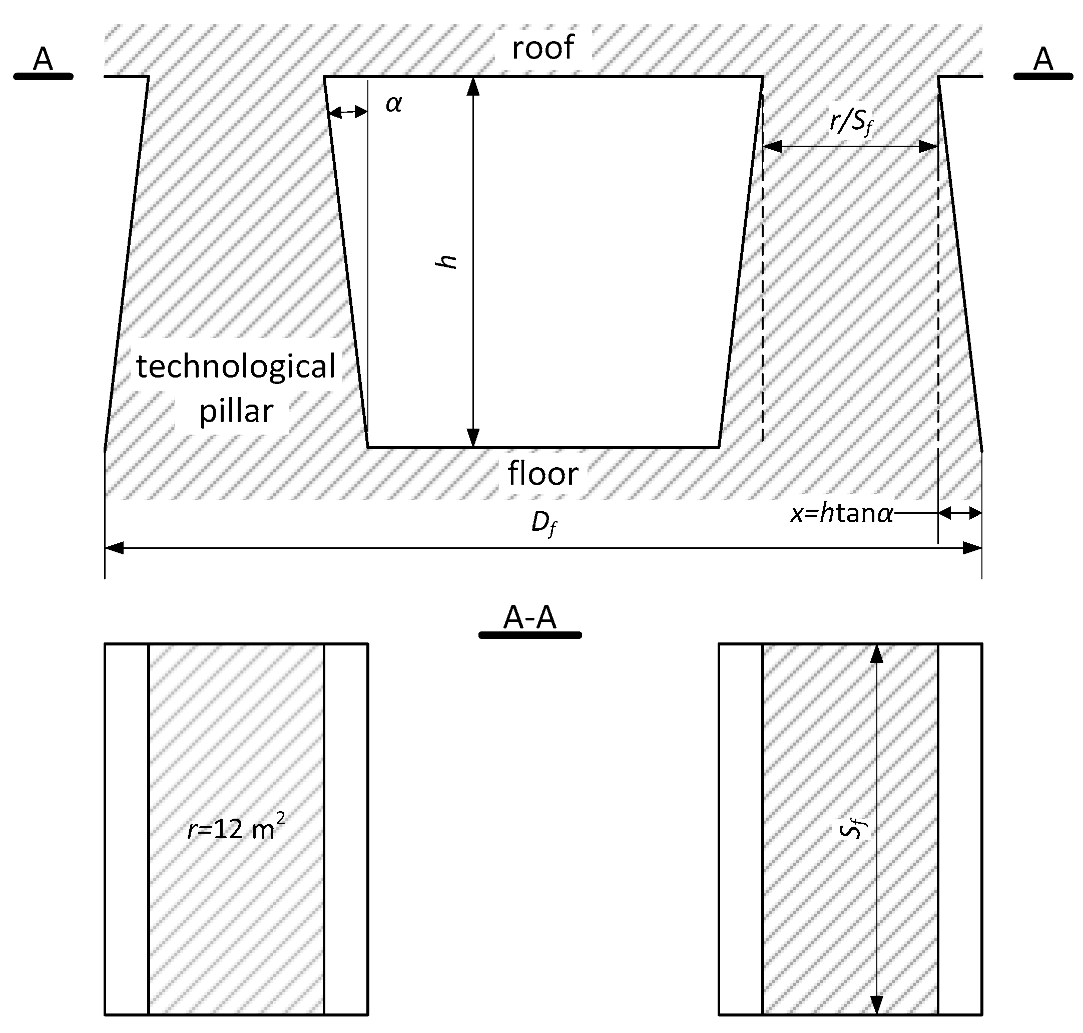
retreating stage in the room and pillar systems consists in cutting the technological pillars into smaller ones. The retreating line remains synchronised with the progress of the cross-cut. The last rows of pillars in front of the goaf are cut with undercuts, usually about 7 m wide.
Figure 6 shows the described situation.
Generally speaking, the minimum area of the remaining pillars measured under the excavation roof is r = 12 m
2, which most often ensures the stability of the roof. Using the expression for the volume of excavated material to be transported from the technological pillar
Vfilara tech., the number of journeys of the transport mode
nLikw for the retreating stage can be described as [
24] as:
Using Formula (5), it is possible to calculate the distance to be covered by the means of transport for the cross-cutting stage, again based on the product dij of the distance to be covered between the loading points for liquidated technological pillars and the unloading point according to Formula (1) and the number of journeys nLikw according to Formula (5).
To meet the condition of a limited time of transport activities to the duration of one shift—for the removal of the entire excavated material—it is crucial to determine the number of transport modes necessary to complete the task. Knowing the dependence determining the distance
dij Formula (1), it is possible to describe the time needed to carry out the haulage cycle
tij taking into account the basic relationship between the distance, velocity and time for uniform straight-line traffic (loading time
tzał and unloading time
troz) were also taken into account [
24]:
where:
tij—haulage cycle time for loading points PZ (h),
tzał—loading time (h),
t′roz—unloading time (h) (
t′roz =
troz for loaders and a set of a loader and one haul truck,
t′roz = 0 for sets consisting of a loader and two or more haul trucks, due to their parallel nature of work),
Vu—the speed of travel with the winning from the loading point to the discharge point (km/h),
V—the speed from the discharge point to the loading point, without the winning (km/h).
The acceleration of the haul truck or the loader and cornering at reduced speed was considered negligible. They will be taken into account indirectly by the average speed of the loaders and haul trucks—the maximum catalogue speeds of loaders and haul trucks, possible to achieve only under ideal working conditions, will not be used in the calculations. Knowing the value of the effective time
tef (h) available during one shift, it is possible to determine the number of journeys between the discharge point and the loading point in the mine face, which can be completed by the loader or haul truck operator [
24]:
where the
Kursij denotes the number of journeys possible for a single transport mode during one shift for a specific effective time
tef and distance
dij.
With Formulas (6) and (7), we can determine, based on the load capacity of
M loaders or haul trucks working in sets, the load that can be transported in
tef time, for a single transport mode [
24]:
where:
Mij—maximum amount (mass) of the winning that can be transported from the loading point PZ (Mg),
M—load capacity of the loader bucket (Mg) or a haul truck.
The calculation of the number of loaders or sets consisting of a loader and a different number of haul trucks
nij necessary for the implementation of the planned tasks does not present any major difficulties [
24]:
where:
nij—number of necessary means of transport,
Mplan—planned mass of the winning to be transported (Mg) during one working shift.
5. Building a Mining Field Exploitation Model—Schedule, Parameterization
The schedule of mining works for the cross-cutting and retreating stages should make it possible to obtain the sum of the costs of road haulage and the emission of pollutants from internal combustion engines related to the transport of the excavated material during the exploitation of the mining field. It is assumed that the model will count the upper level of HC+NOx emissions resulting from individual Stage standards. The basic assumption when building the simulation model is to include in the exploitation model of the mining field the geometric dimensions of drifts and pillars. The collected data will be used to calculate the distance covered by the transport means. Additionally, it is necessary to define the location of the planned discharge points, their location in the bundle of contouring drifts, in a specific intersection and the drift.
The size of the tested field of exploitation is determined by specifying the number of drifts and intersections and numbering them accordingly. The distances for which the excavated material is transported for the entire field of exploitation are calculated. Similar activities are carried out for the retreating stage, additionally taking into account the location of the protective pillars.
The next step in building the model is to describe the tire haulage measures that are to be included in the model. The loaders are described by the following parameters: effective working time, loading and unloading time, load capacity, driving speed with and without the material. For the sets consisting of a loader and a variable number of haul trucks, additional parameters include the number of buckets needed to load the winning onto the haul truck and the number of HT. The entered data characterize machines with the symbols LHD2, LHD3, LHD4 (the main difference between them is the load capacity and operating cost) and the LHD2 + 1×HT, LHD2 + 2×HT, LHD2 + 3×HT and LHD2 + 4×HT sets. Other important parameters are the amount of the winning planned for transport during one shift, rock density of the excavated material and the operating cost of loaders and haul trucks per shift. A table of haulage costs for a given amount of the winning from the haulage distance will be calculated. The condition is checked whether a given loader/set can complete the task within the effective working time; if not, the task can only be performed with a larger number of machines/sets. On this basis, the most cost-effective centre of the tire haulage for a given distance and amount of excavated material is found (what will be explained in detail in
Section 6).
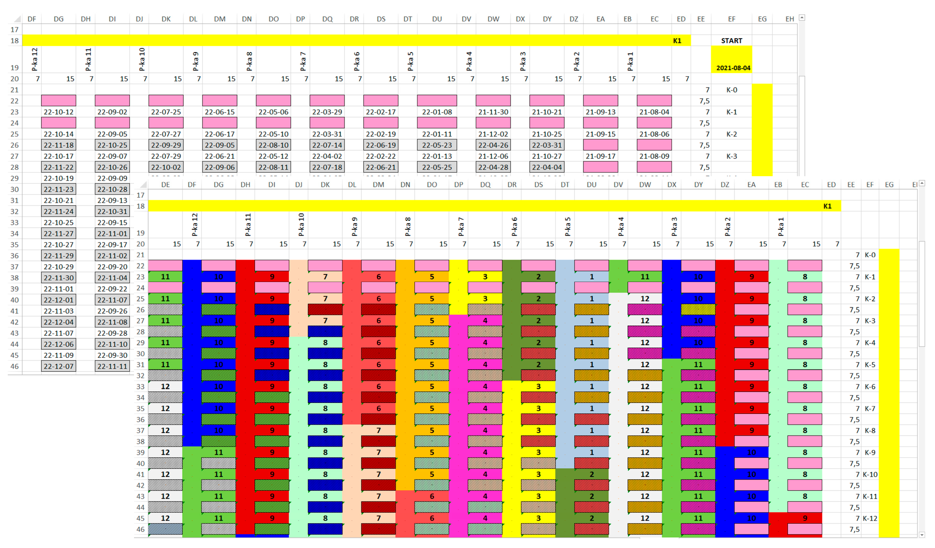
The designated work schedule for the analyzed mining field covers separately cross-cutting and retreating stages. The commencement date of works for the cross-cutting and retreating stages should be specified, necessarily taking into account the weekdays and so-called “Black Saturdays”. Only the shifts during which mining is conducted are taken into account. To plan the progress of works for the mining field, it is necessary to remember about the necessity to plan the level of extraction for the entire period in which the analyzed field is intended to be exploited. For further calculation steps, the daily output from the so-called volumetric changes is evenly divided between the cross-cutting and retreating. Determining the planned amount of output between shifts makes it possible to divide the daily production, e.g., on Saturday, 30% of the daily extraction is performed on the first shift, 70% on the second, shifts 3 and 4 do not carry out mining works. To take into account the sequence of works carried out for the cross-cutting stage, and thus to reproduce the behaviour of the wings of the extraction front, the order of operations is defined manually by assigning consecutive numbers until all intersections of the drifts in the exploitation field are described. Then, the planned sequence of retreating of individual pillars, remaining after the cross-cutting stage, is also introduced. The result of the calculations performed in the schedule will be not only the designation of the end of operation date for the cross-cutting and retreating stage (
Figure 7) but also the assignment of the means of transport with the highest value of the objective function for each shift, until the completion of mining works.
To calculate the schedule of the progress of mining works, it is also necessary to propose the dates of construction of reloading points on conveyor belts that collect the excavated material transported using wheeled haulage. Thanks to the synchronization of the dates of availability of reloading points with the extraction front, the greatest benefits from the shortening of the tire haulage routes might be achieved.
The set of calculation parameters is presented in
Table 2 and
Table 3. The parametric nature of the model should be emphasized; the calculations are carried out based on the geometric dimensions of the mining field, the quantities characterizing various types of means of transport and the method of field exploitation (the level of extraction, mining works on specific days of the week).
In the simulation model, the starting dates of the cross-cutting and retreating stage were adopted, bearing in mind that the retreating stage takes place immediately after the cross-cutting. Residual pillars must not lose their load-bearing capacity, decreasing over time, which ensures the stability of the roof. The weekly schedule of mining works includes 4 shifts, five workdays a week and selected working Saturdays. The retreating is not carried out during the night shift, the effective time for mining works was assumed to be tef = 3.5 h. The value of the winning density, based on the example of copper ore, was assumed to be 2.32 Mg/m3, it was necessary to recalculate the relation between weight and volume.
The production plan Mplan took into account the average planned mass of the winning to be transported—obtained from the mine faces—by the stage of cross-cutting and retreating, was 3 615 Mg. A certain extraction fluctuation between the individual months of mining was also introduced (to increase the model’s adequacy), the average deviation was approximately 70 Mg.
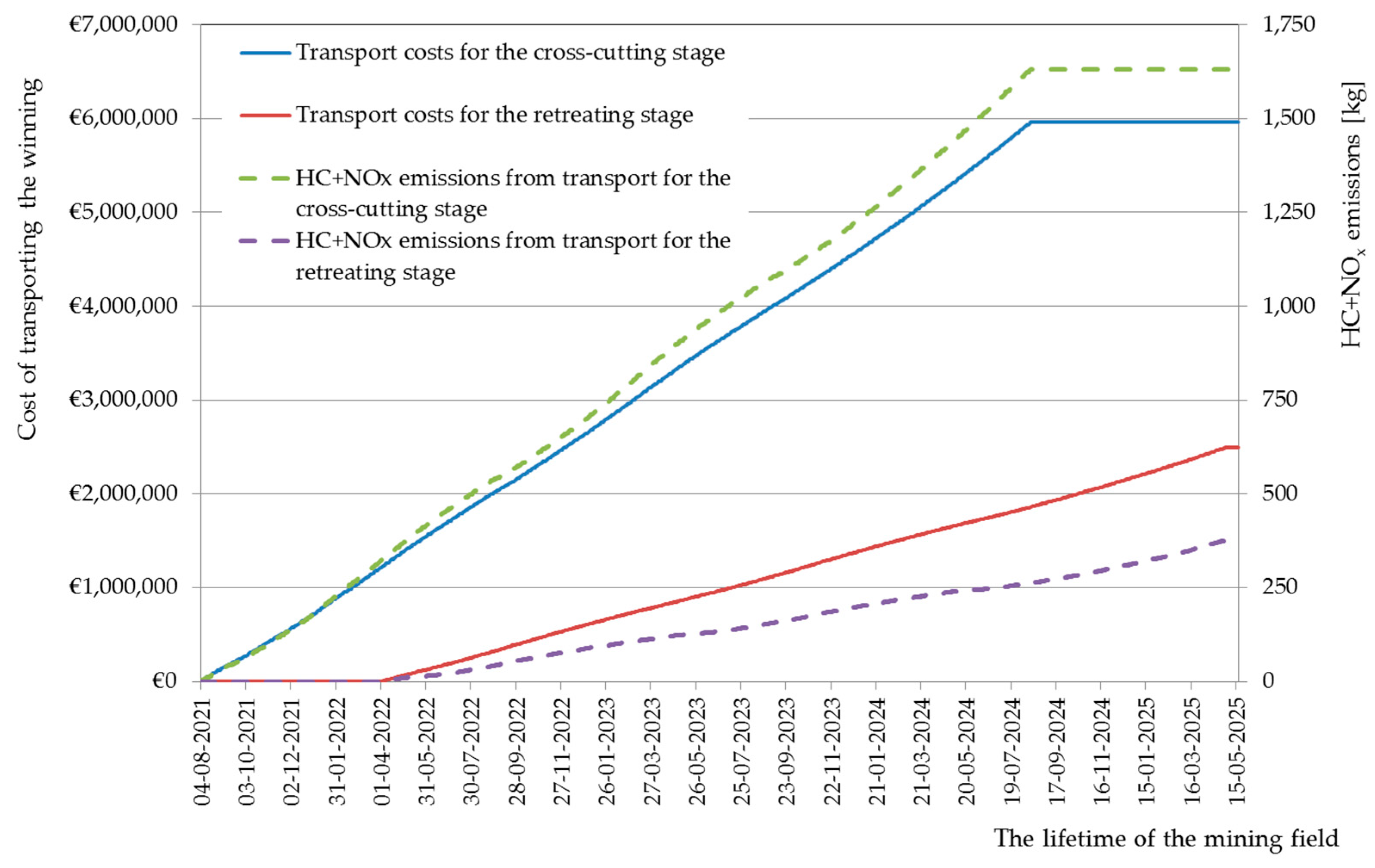
When calculating the schedule, data on the costs of tire haulage for the cross-cutting and retreating stages as well as HC+NO
x emissions are collected, as shown in
Figure 8.
A slight fluctuation in the rate of increase in the total costs of transporting the excavated material and the amount of HC+NO
x emissions during the exploitation of the mining field, shown in
Figure 8, results from the increase in the distance between the mine faces and discharge points as the extraction front line moves. At the moment of launching the next discharge point, the distance for which the winning is transported gets reduced, thus the rate of increase in costs and the amount of HC+NO
x emissions decreases. Then, the distance begins to increase again, together with moving away from the discharge point. The costs of transporting the excavated material are limited by the mechanism of selecting the least expensive means of transport; the obtained results are shown in
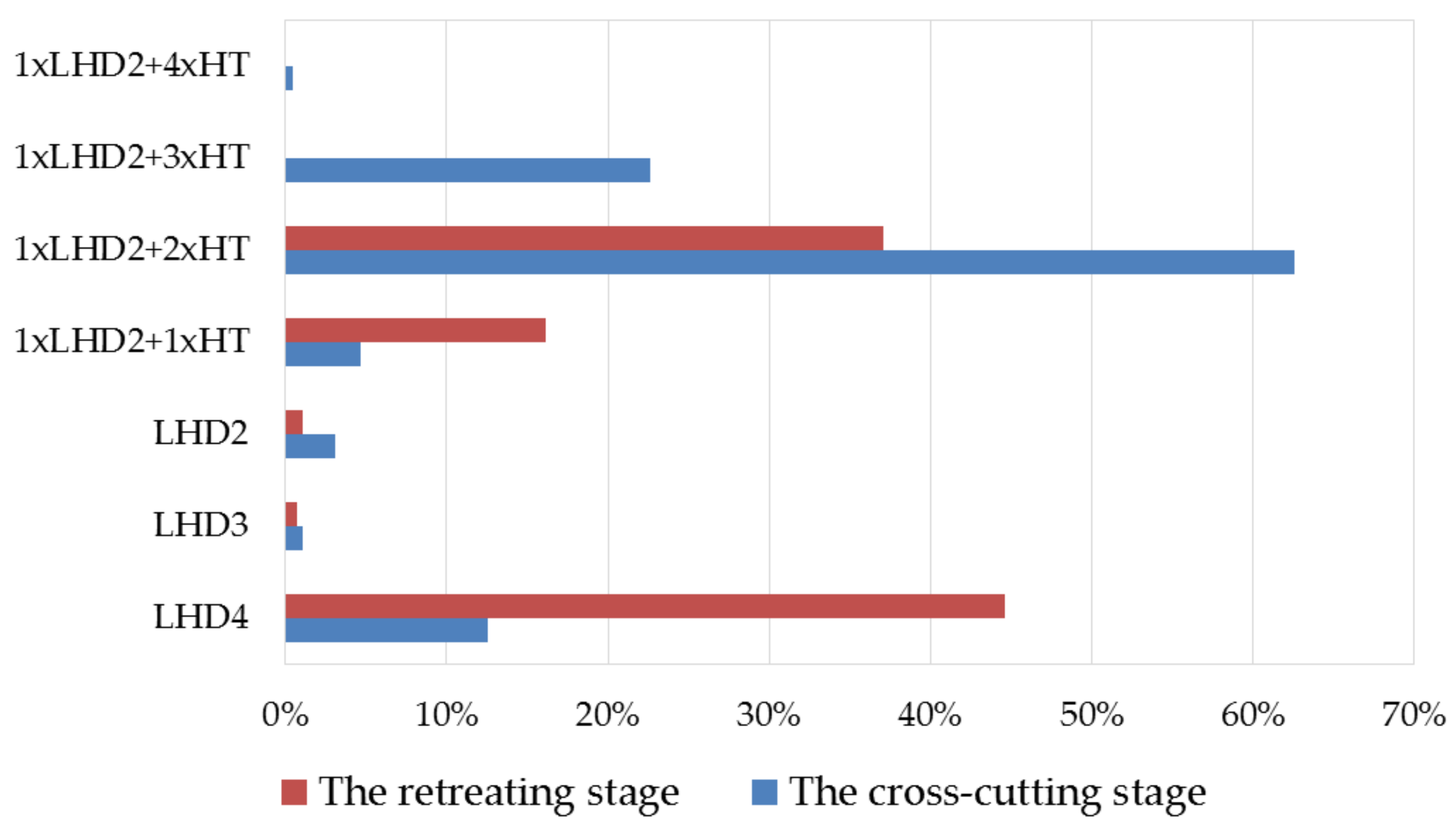
Figure 9.
For the cross-cutting stage, the most frequently chosen means of transport is the set of 1×LHD2 + 2×HT (62%) and LHD4 (12%), while during the retreating stage these proportions change: LHD4 (45%) and 1×LHD2 + 2×HT (37%). Other types of means of transport are chosen much less frequently. The crucial difference between these two stages while selecting the means of transport is the smaller amount of the winning to be obtained from the pillars at the retreating stage.
6. Method of Selecting Means of Transport, Taking into Account Environmental Aspects
For the simulation studies, the idea of a means of transport selection mechanism was proposed to select the type of a loader or a set not only according to the lowest cost criterion, but also taking into account the differences in HC+NOx emissions between them, suggested to be used as the second selection criterion.
The method proposed in the book [
24] allowed us to determine the most cost-effective type of transport for a given distance and amount of the winning to be transported between the loading and the discharge points:
where:
Kij—the total cost of transport between the loading point and the discharge point, converted into (EUR/Mg),
koszt—the sum of costs incurred for the operation of the machine during one shift (EUR). The cost variable should be understood as the sum of the costs of:
Operation of the loader: necessary fuel and oils, consumables;
Purchase costs, taken into account as depreciation;
Maintenance services;
Operator’s salary with margins.
The most cost-effective type of transport is certainly the cheapest resource, marked as the
Zopt variable [
24]:
where
Z marks the set of types of transport means.
The emission of HC+NO
x pollutants, which occurred during the transport of the winning during one shift for a specific means of transport, was calculated in the field exploitation model during the scheduling of mining works from
Section 5, based on the formula:
where
Eij—the calculated amount of HC+NO
x pollutant emissions for one shift [g/working shift] for the selected number of means of transport,
Estage—HC+NO
x emission levels according to individual Stage standards [g/kWh],
η—engine power utilization during a working shift (%). Similarly to the methods of estimates [
2,
3] determining fuel consumption used by manufacturers of means of transport, it was assumed that the loader uses 40% of the engine power and the haul truck in 50%. The formula also takes into account the number of means of transport
nij necessary to ensure transport capacity and the effective time
tef of their work.
For the loader plus haulage vehicles, Formula (12) was used, for each of the machines that make up the set, the emissions from different types of means of transport were summed up. It was assumed that the means of transport the least harmful for the environment is a loader or a set of loader and haulage vehicles with the lowest HC+NO
x emission, according to the formula:
The objective function of the method of selecting the means of transport for the winning in the room and pillar mining systems was based on the expression:
where
w1 and
w2 are the weights determining the shares of criteria in the objective function. Additionally, the function of the weights is to balance the impact of criteria in the case of a large difference in their numerical values.
Using the field scheduling model, it was then decided to determine HC+NOx emission levels for loaders and haul trucks meeting Stage II, Stage IIIA, Stage IIIB and Stage IV emission standards.
7. Results of Simulation Studies
Based on the expressions presented in the above sections, a simulation model was prepared to schedule the progress of mining works in the room and pillar systems. In this model, the selection of means of transport was based on the method proposed in
Section 6, taking into account environmental aspects. The calculated HC+NO
x pollutant emission level for the transport of the winning with tire haulage was used as one of the criteria for evaluating the solution (Formula (13)) as a function of the objective (Formula (14)).
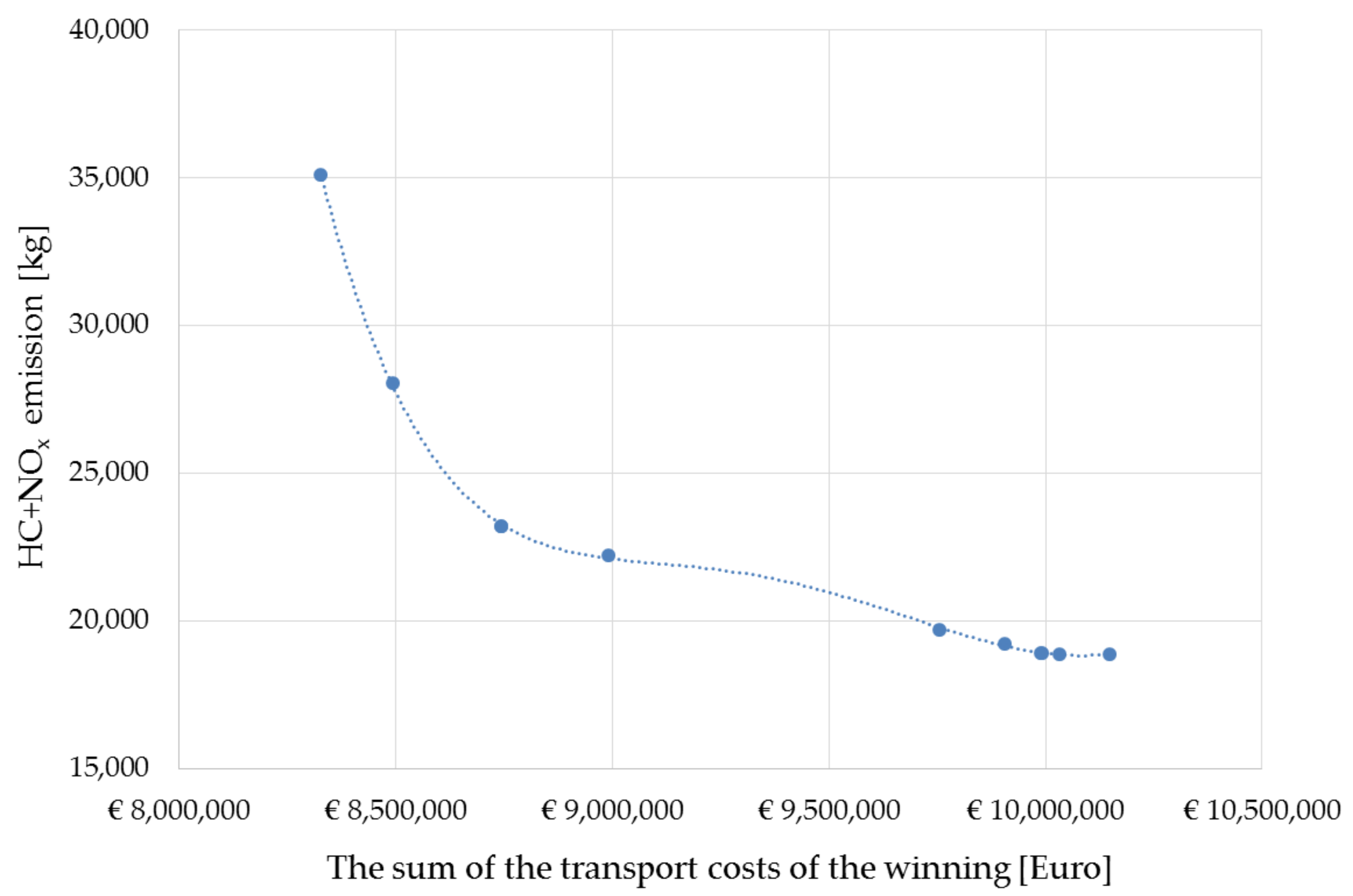
For the first simulation tests, the implementation of transport with vehicles meeting the Stage II emission standard was assumed. For the calculations, the pairs of weights in the range
w1 = 0 and
w2 = 1 (the situation in which the cost of transport is negligible, the result in 100% is determined by the minimum level HC+NO
x) up to
w1 = 1 and
w2 = 0 (the situation in which the result in 100% depends on the cost of transport, while HC+NO
x emissions are not taken into account) were adopted. The calculation results are presented in
Figure 10.
It is not surprising that the highest level of HC+NO
x emission was recorded with the minimum cost of the winning transport during the exploitation of the mining field. It is interesting, however, that it is possible to significantly reduce the level of HC+NO
x emissions (from 35,110 to 18,860 kg over more than 3 years of operation) by the skilful selection of the type of means of transport, even if all loaders and haul trucks meet the same Stage II standard. The potential of a possible reduction of HC+NO
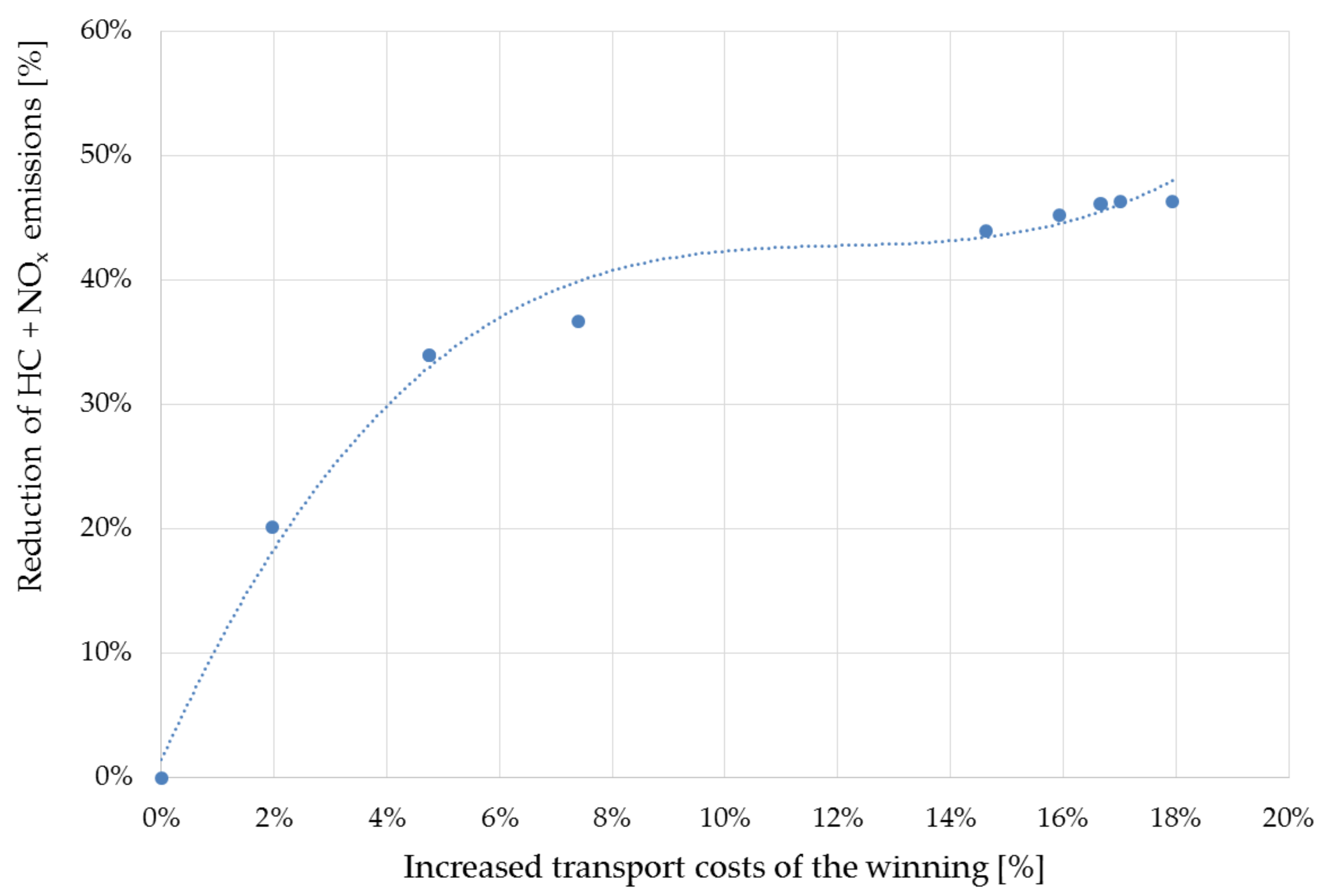
x emissions is better illustrated by the presentation of percentage values—
Figure 11.
The obtained dependence shows that a 20% reduction of HC+NOx emission is possible using the proposed method of selecting the means of transport, with a 2% increase in the cost of the winning transport. The nature of the dependence is similar to the well-known Pareto principle, although an 80% reduction of emissions turned out to be impossible to achieve, regardless of the costs of transporting the output.
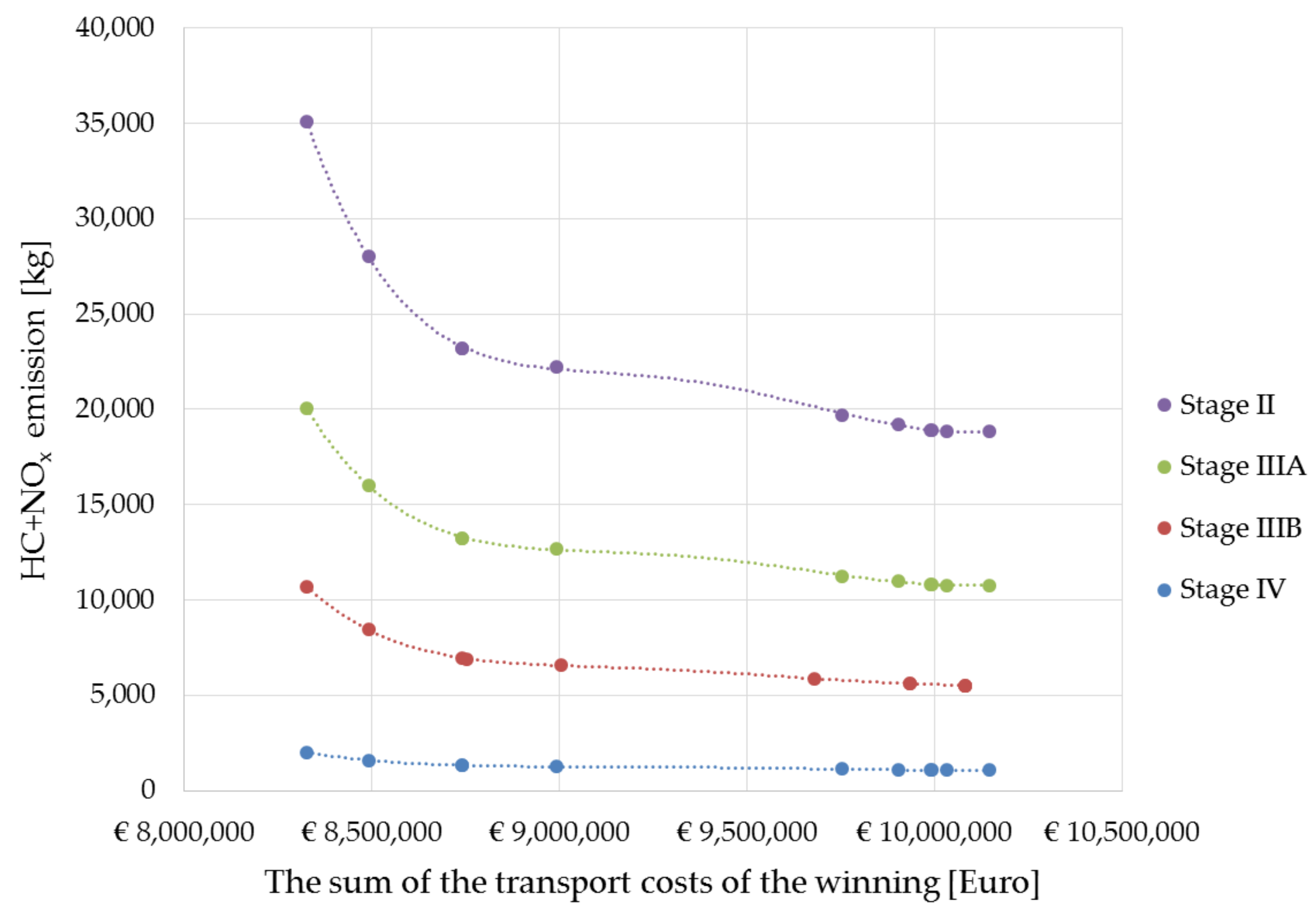
Further simulation tests were carried out with the assumption that the deep mine replaces the means of transport for those complying with Stage IIIA, Stage IIIB and Stage IV emission standards. Analogous simulation tests on the method of selecting the types of transport means according to the objective function (expression 14) were carried out, as presented for Stage II standards. The results of the calculations are presented in
Figure 12 to facilitate comparison.
The proposed method has proven successful in the case of using loaders and haulage trucks meeting Stage IIIA, Stage IIIB and Stage IV emission standards for the transport of the winning. The calculations show a reduction in HC+NOx emissions during the transport of the winning from 35,110 kg for the Stage II standard to 1077 kg for the Stage IV standard. This is a very large reduction that confirms how restrictive the current standards are, while the permissible level of HC+NOx emission for the combustion engines in the power range from 56 to 560 kW is the same for Stage IV and Stage V.
The driving style of the loader and hauler operators also has an impact on exhaust emissions. Unfortunately, we did not have portable emissions measurement systems (PEMS), nor did we have permission from the mine management to make such measurements. The solution to this problem was to use for calculations the permissible emission values resulting from Stage standards, being aware that the actual emission of pollutants during ore transportation is even higher than it results from the presented simulation calculations.
8. Discussion and Conclusions
The proposed method makes it possible to optimize the selection of the type of the winning transport in deep mines using the room and pillar exploration system, on the basis of the objective function based on two criteria: minimizing the cost of transporting the winning and the level of pollutant emissions in the exhaust gas (on the example of HC+NOx). The method is based on scheduling the progress of mining works carried out according to the room and pillar exploration system, taking into account the stages of cross-cutting and retreating. Its basic assumption is to take into account the geometric dimensions of drifts and pillars as well as various means of transporting the excavated material in order to be able to perform calculations for different cases of mining fields. Calculated 20% reduction in HC+NOx emissions with a 2% increase in transport costs shows the great potential of the developed method.
The advantages of the presented method and algorithms include the fact that PM emissions can be counted in the same way using the Stage or Tier emission standards set by the United States Environmental Protection Agency (EPA), as well as the mass of exhaust gases from internal combustion engines of mining machines. For this purpose, theoretical assumption that the combustion engine of the mining machine is powered by a mixture with twice the excess air and burning 1 kg of diesel oil means taking about 30 kg of air from the environment, might be applied. With an average fuel consumption of about 30 kg per hour of work, this means taking about 900 kg of air during this time and emission of a similar mass of exhaust gases to the excavation site [
25], which can be easily recalculated into the mass of exhaust gases emitted during one working shift.
The idea of selecting the means of transporting the output (loaders and haul trucks) not only for efficiency and economic reasons, but also using the ecological criterion, may be useful not only during the operational management of transport processes. There is a potential possibility of using it when deciding which means of transport to supplement the existing machinery park in deep mines with; at purchase of new means of transport, preceded by an analysis of costs and levels of pollutant emissions from internal combustion engines. Another potential direction for the expansion of the mining field exploitation model is the possibility of taking into account the emission of pollutants or the mass of exhaust gases from other types of mining machines used, which should be interesting in the context of issues related to ventilation of workings.
Finally, there is the question of whether the calculated values of pollutant emissions from mining machinery exhaust gases, additionally spread over several years of mining field operation, are significant for the natural environment? When looking for an answer to this question, the scale of the phenomenon should be taken into account: at the same time, in one large mining concern, as many as 150–200 mining fields are operated in a room and pillar system. Deep mines have fiscal obligations related to environmental protection, resulting, inter alia, from the method of their exhaust shafts functioning, and they incur—perhaps too low—environmental charges for the emission of each ton of gas.


