Article

A Hybrid Control Approach for the Swing Free Transportation of a Double Pendulum with a Quadrotor

1
Faculty of Engineering of Gipuzkoa, University of the Basque Country, UPV/EHU, 20018 San Sebastian, Spain
2
Faculty of Engineering of Vitoria, University of the Basque Country, UPV/EHU, 01006 Vitoria-Gasteiz, Spain
3
Faculty of Computer Science, University of the Basque Country, UPV/EHU, 20018 San Sebastian, Spain
*
Author to whom correspondence should be addressed.
Appl. Sci. 2021, 11(12), 5487; https://doi.org/10.3390/app11125487
Submission received: 5 May 2021 / Revised: 2 June 2021 / Accepted: 8 June 2021 / Published: 13 June 2021
(This article belongs to the Section Robotics and Automation)

Abstract

:
In this article, a control strategy approach is proposed for a system consisting of a quadrotor transporting a double pendulum. In our case, we attempt to achieve a swing free transportation of the pendulum, while the quadrotor closely follows a specific trajectory. This dynamic system is highly nonlinear, therefore, the fulfillment of this complex task represents a demanding challenge. Moreover, achieving dampening of the double pendulum oscillations while following a precise trajectory are conflicting goals. We apply a proportional derivative (PD) and a model predictive control (MPC) controllers for this task. Transportation of a multiple pendulum with an aerial robot is a step forward in the state of art towards the study of the transportation of loads with complex dynamics. We provide the modeling of the quadrotor and the double pendulum. For MPC we define the cost function that has to be minimized to achieve optimal control. We report encouraging positive results on a simulated environmentcomparing the performance of our MPC-PD control circuit against a PD-PD configuration, achieving a three fold reduction of the double pendulum maximum swinging angle.

1. Introduction

The research community has studied different approaches for the aerial transportation of payloads task and since the 70s. Specifically, towed cable systems have been analyzed in various applications like payload delivery, kites, aerial refueling systems, brick transportation, and rescue missions. The enhancements of these tasks would permit a wider spectrum of possibilities for unmanned aerial vehicles (quadrotors), including transportation of bigger and different types of objects, inspection and maintenance of elements and surfaces, and emergency services related applications.
In recent years, there has been extensive interest in developing solutions for delivering a payload by connecting it to a multirrotor quadrotor with cables [1,2,3,4]. In these approaches the payload is often considered to be a particle mass at the end of the cable. We call this suspended load, which is also known as slung load. Despite the different alternative quadrotors considered in the literature to transport such payload, in this article we will focus on quadrotors. Quadrotors deployment of cable-suspended payloads can save time and energy, comparing to other methods, and thus, this configuration provides potential benefits that may extend the application possibilities of these aerial systems [5]. However, its passive dynamics affect the performance of the quadrotor, by the introduction of a new set of inputs, such as tensions and residual vibrations. Quadrotors are a nonlinear, unstable and underactuated system, and coupled dynamics with the attached payload adds an extra complexity and alters the performance of precise positioning and path-following, and thus it is required a careful control design in order to cope with them. The problem is far from being solved [6,7].
Research on payload stabilization suspended by a cable started decades ago, when dealing with the control of cranes whose payload was modeled by a lumped-mass [8]. This model is simple, but it captures the complex dynamics of payload motion. Classic equations of applied mechanics were used to model a suspended load in cranes [9], and later extended in [10]. Nowadays, the stabilization of the slung load is pursued through the minimization of the particle mass swing, which enables the reduction of the vibrations and sudden shock in the quadrotor dynamic system. It is known that the transportation speed and the removal of the payload oscillations are contradictory control goals [11], therefore, the fulfillment of both objectives represents a challenging task for control engineering.
First research works on payload transportation by quadrotors appeared in the late 1990s [12,13]. Early attempts involved quasi-static motions to position and orient a suspended load [1]. Since then, the most common dynamic modeling is the lift vector of a payload to be fixed along the z-direction in the frame fixed to be quadrotor body, so that quadrotors can only generate their translational motion by tilting the body frame by the propellers in a certain direction. Usually, for these systems a cascade control configuration is used, where an outer-loop controller is in charge of the translational control and then, an inner loop is used to obtain the tilt angle calculated by the outer loop. For instance, [14] use a Model Predictive Controller (MPC) strategy and linear-quadratic regulator (LQR) control for slung load operations in hover and aggressive maneuvers, while [15] use the swinging load angles as an error input for a proportional derivative (PD) controller that corrects the translational controller during paths and maneuvers.
An alternative way to deal with the dynamics of the suspended load is to incorporate it directly into the quadrotor control dynamics. In [16], the authors present a multi-rotor with a hybrid system, interchangeable between a taut or a flexible cable. Depending on the maneuvers to be done and obstacles found, the quadrotor control switches between the two configurations thanks to a mixed-integer quadratic programming. In [17], the authors use a Hamiltonian approach for the control of the nonlinear system, where the swinging oscillations are controlled by an interconnection and damping assignment-passivity based control. Geometric control is utilized in [18] in the model of cable decomposed in a series of linear linked pieces. Adaptive control and slung load pose estimation for small size quadrotors has been also introduced [19].
In the last years, artificial neural network (ANN) based algorithms are being tested for the control of quadrotors, despite their limitations in size, weight, power consumption, and response to the changing environments and flying conditions, which require a continuous retraining process of the ANN architecture [20], even more so in payload transportation applications. Besides the application of deep learning for quadrotors artificial vision navigation systems [21], classical control strategies have been proposed, like MPC for the elimination of the overshoot at load release time [22], or a reinforcement learning strategy based on the minimization of the payload oscillations for an automated cargo delivery [23].
Conventional PD controllers have proven to be an efficient solution for inner control loop in payload transportation task by quadrotors, due to their simplicity, robustness and good results [6,19,24,25,26]. Adaptive PID controller can be employed for coping with wind disturbances and main external forces that affect the performance of the system [5,25]. On the other hand, the MPC is designed to solve an optimization problem by defining and minimizing an objective function which is related to both the optimal state and control inputs. Although the interest towards this configuration gained the attention of researchers in recent years [27,28,29], they still did not solve completely all the problems or explore the possibilities related to it.
The state of the art in transportation of slung loads with quadrotors can be broadly classified into two categories [4]: (a) Feedback control for tracking desired payload trajectories [17,18]. (b) Trajectory planning for a quadrotor with a slung load [30,31,32,33].
This paper follows the second approach. As in most of the prior works, the following dynamic simplifications were made without losing precision in the results: (1) The aerodynamic effects of the quadrotor and the payload are neglected. (2) The dynamics and perturbations of the payload are considered completely decoupled from quadrotors, considering that the the payload motion is bounded [33]. (3) The cable model is taut and non-elastic. (4) We consider the 2D plane XZ for the modeling of the double pendulum [34,35]. These assumptions are considered to be realistic enough for the dynamic modeling of the quadrotor + slung load system, except when the quadrotor enters aggressive maneuvers [36]. According to [37], the discretization of the pendulum in two mass particles and massless and taut links represents a valid approach for the current study purpose, and it requires lower computational cost and offers very similar results. Moreover, the usage of the pendulum mathematical model as the DLO physical model widens the research possibilities, as it permits an easier dynamic calculus of taking off and landing, which is not a fully studied field [7]. Very recent works deal with the control of the transportation by an quadrotor of a payload modeled as a double pendulum [38,39,40].
The contributions of this paper are as follows: We present a control configuration with a PD controller embedded in a MPC controller to transport a double pendulum swinging free and smoothly. The double pendulum is a highly nonlinear and unstable multi-body solid. The PD controller is used for quadrotor attitude control while the MPC pursues the precise translational control that tries to minimize the oscillations of the payload. The considerations of the shocks of the two mass particles represent a big challenge for the motion control of the quadrotor. The control strategy is validated in a parabolic ascending trajectory of the quadrotor, comparing the proposed MPC-PD controller against a PD-PD controller that tackles quadrotor path tracking, but not pendulum swing minimization.
The article is structured as follows: The dynamic modeling of the quadrotor and the pendulum is described in Section 2. In Section 3, the control strategy developed in this work is detailed. The experiment and results to test the efficiency of this approach are reported in Section 4. Finally, conclusions are presented in Section 5.

2. Dynamic Modeling of the System

Figure 1 shows a schematic model of the quadrotor transporting a double pendulum. In this system, the suspended load system consists of two mass particles m 1 and m 2 connected by massless straight-line links of length l 1 and l 2 which support forces only along the link, and it is suspended from a single point in the center of the quadrotor. The double pendulum links describe angles θ 1 and θ 2 in the plane XZ. In next subsections, the dynamic modeling of the quadrotor and the double pendulum are going to be described.

2.1. Double Pendulum System

The highly nonlinear dynamics of double pendulums are still of interest to scientists [41]. Transportation of a payload by a hook attached to the quadrotor corresponds to this double pendulum paradigm, where the hook is the first mass and the payload the second [40]. Figure 1 shows the experimental setup, where the bars of the pendulum are assumed massless. The equations describing the coordinates of the double driven pendulum masses are given in Equation (1), where x 0 and z 0 represent the quadrotor instantaneous position, and the rest of coordinates refer to the absolute position of every punctual mass. In order to simplify computation, in this paper we will work in 2D, i.e., over the X Z plane:
x 1 = x 0 + L 1 sin ( θ 1 ) z 1 = z 0 L 1 cos ( θ 1 ) x 2 = x 1 + L 2 sin ( θ 2 ) z 2 = z 1 L 2 cos ( θ 2 )
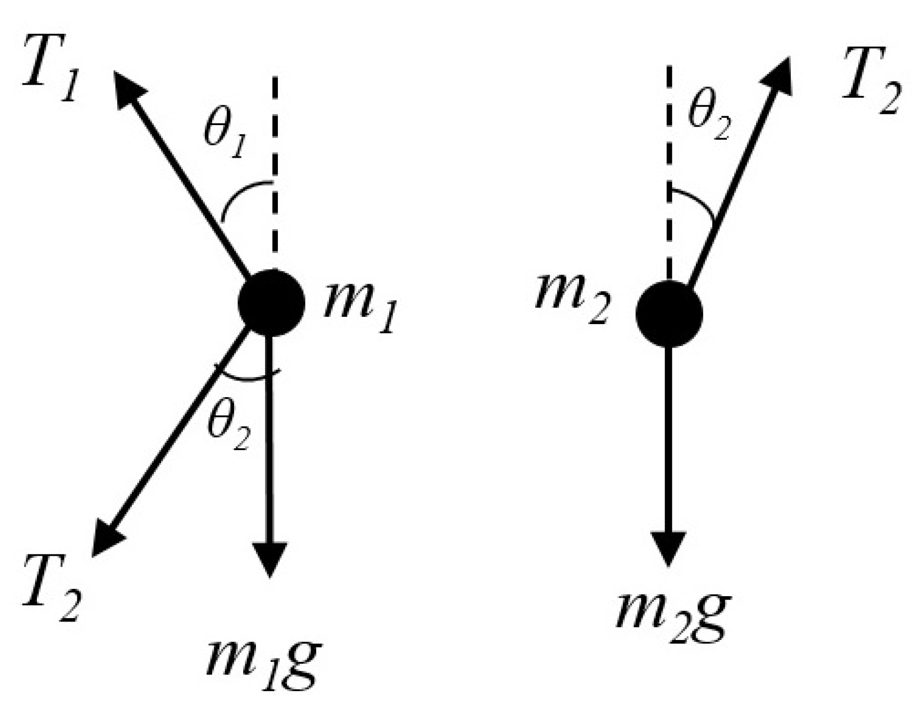
A computer algebra program was used to infer the equations for θ ¨ 1 and θ ¨ 2 in terms of θ ¨ 1 , θ ¨ 2 = f θ 1 , θ 2 , θ ˙ 1 , θ ˙ 2 . The resulting equations are omitted due to its big size. The dynamics of the double pendulum are summarized in Figure 2, where T 1 and T 2 are the tension of the first and second link, respectively. Thus, the tension affecting the quadrotor is T 1 . Applying fundamental results of Applied Mechanics, we can deduce the dynamic equations expressed in the horizontal and vertical coordinates given by Equation (2):
m 1 x ¨ 1 = T 1 sin θ 1 + T 2 sin θ 2 m 1 z ¨ 1 = T 1 cos θ 1 T 2 cos θ 2 m 1 g m 2 x ¨ 2 = T 2 sin θ 2 m 2 z ¨ 2 = T 2 cos θ 2 m 2 g
Again, with the help of an algebraic manipulation program, we derive the equations for T 1 and T 2 , which we omit here for reasons of space. We can consider the quadrotor+slung load system as an quadrotor with bounded disturbances. Specifically, we take into account the Z and X projections of T 1 , namely T 1 X and T 1 Z , for use in the following subsection.

2.2. Quadrotor Dynamics

The governing equations of the lift and torques generated by the propellers are as follows:
U 1 = b Ω 1 2 + Ω 2 2 + Ω 3 2 + Ω 4 2 , U 2 = l · b Ω 2 2 + Ω 4 2 , U 3 = l · b Ω 1 2 Ω 3 2 , U 4 = d Ω 1 2 + Ω 2 2 Ω 3 2 + Ω 4 2 ,
where U 2 , U 3 and U 4 are the roll, pitch and yaw torques, respectively, and Ω i 2 is the squared speed of the i-th propeller, and U 1 is the total thrust of the quadrotor. The parameter b and d are the thrust and drag coefficients, respectively.
Angles ϕ , θ , and ψ represent the Euler angles referring the Earth inertial frame with respect to the body-fixed frame of quadrotor ( ϕ , θ and ψ represent the rotation along axis X, Y and Z, respectively). Equation (4) provides necessary modifications for angular and linear accelerations (considering that ψ , ψ ˙ = 0 ) . I X X , I Y Y , I Z Z are the inertia moments around the X, Y and Z axis, and m is the mass of the quadrotor. Finally, T 1 Z , and T 1 X are the T 1 components in X and Z directions.
x ¨ = cos ϕ sin θ m U 1 + T 1 X y ¨ = sin ϕ m U 1 z ¨ = ( cos θ cos ϕ ) U 1 m + g + T 1 Z ϕ ¨ = U 2 I x x θ ¨ = U 3 I y y ψ ¨ = U 4 I z z
The integration of Equation (4) is calculated with the Euler method. Though the numerical integration procedure can be critical for highly nonlinear systems, such as chaotic systems [42], our system is smooth enough to allow for this computationally cheaper approach. Considering that the control horizon of MPC control for the quadrotor application is 1 s , we have found in the recent literature that Euler provides a good balance of numerical precision and stability, and quick response for real time applications [43,44].

2.3. Linearization and Discretization of the Model

The system nonlinear model must be linearized around the equilibrium/hover conditions in order to to solve the equations that provide the optimal parameter values of the linear controllers. For simplification, we keep constant ψ = 0 . Using the Linear Time Invariant discretization model, we can assume that the quadrotor and double pendulum dynamics can be simplified. We can calculate the first order Taylor series around the equilibrium point ( x e q , u e q ) of the nonlinear dynamics of the quadrotor obtaining [45] the following equation:
x k + 1 = A x k + B u k , y k = C x k ,
where the x k , u k and y k vectors are the state space, input and output vectors, respectively, defined as follows:
x k = [ x Q y Q θ L 1 θ L 2 x ˙ Q y ˙ Q θ ˙ L 1 θ ˙ L 2 ] T ,
u k = [ f ϕ r e f θ r e f ] T ,
y k = [ x Q y Q θ L 1 θ L 2 θ ϕ ] T .
The linearization is developed around an equilibrium point at which the quadrotor and the slung load system can hover on a specific position ( x , y , z ) . Thus, f = m g + ( m 1 + m 2 ) g , where m 1 and m 2 is the mass of the pendulum particles as shown in Figure 1. We have that the equilibrium conditions translate into:
ϕ r e f = θ r e f = 0 ,
and the equilibrium vectors result in:
x e q = [ x Q y Q 0 0 0 0 0 0 ] T ,
u e q = [ m g + ( m 1 + m 2 ) g 0 0 ] T .

3. Control System

3.1. MPC-PD Control Configuration

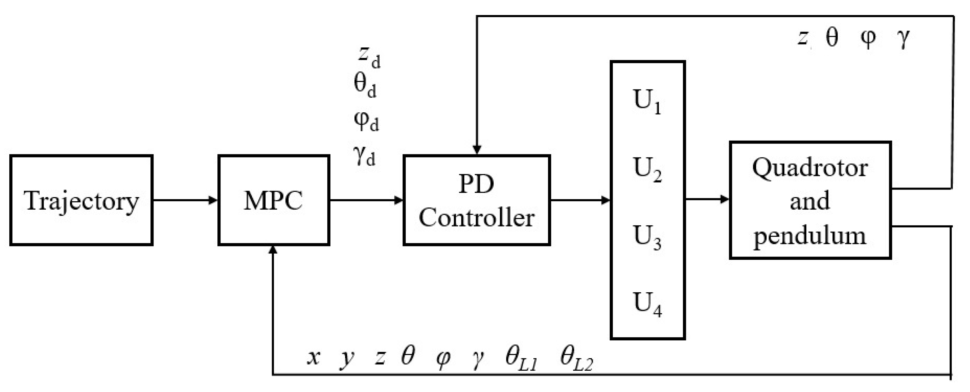
The control configuration we use in the quadrotor and double pendulum system is shown in Figure 3. For generalization purposes, variables that are not used in the actual experiment are also included, such as Y axis or ψ angle. For reproducibility purposes we have published our code in (http://www.ehu.eus/ccwintco/uploads/3/36/MPC-double-pendulum.zip accessed on 7 June 2021).
  • The PD controller computes the quadrotor torques and lift in Equation (4). It consists of four decoupled Single Input Single Output (SISO) PD circuits, each in charge of one of the four degrees of freedom (z, ϕ , θ and ψ ). The PD equation is a discrete time controller, where the error derivative is obtained with the division of two consequent error in time and the chosen time increment. The main equation of the PD control is shown next:
    u ( t ) = K P e ( t ) + K D d e ( t ) d t ,
    where e ( t ) is the difference between the desired value of each degree of freedom (denoted by subindex d) and the actual value in each discrete moment. K P and K D are the gain of the proportional and derivative terms, respectively.
  • The MPC block is in charge of computing the desired attitude angles minimizing the payload swing ( z d , ϕ d , θ d and ψ d ). MPC is a class of advanced process control methods [46] which computes the optimal control parameters of the system in finite window of time, denoted the control horizon, and then applies the first step in this control horizon. The process goes on moving the control horizon one step ahead. The algorithm minimizes a cost function, consisting of the error between the output and desired tracking state, subjected to some constraints. Our MPC controller is designed over a discrete-time state space linear time-invariant (LTI) system, the linearization of the double pendulum dynamic system described in Section 2.3. We apply a Kalmann filter for the prediction of the states in the control horizon, thus we have a Robust MPC, that has shown promising results in highly nonlinear quadrotor related applications [47,48].
Our cost function will be the minimization of the difference between the quadrotor position and the desired trajectory and the minimization of the control inputs, thus resulting in Equation (13):
J = ( x N x N * ) T P m ( x N x N * ) + i = 0 N 1 [ ( x i x i ) T Q ( x i x i * ) + u i T R u i ] ,
where the control horizon is denoted by N. The terminal state and its desired state are denoted by x N and x N * . P m is the weighting matrix for the motor states. Finally, the reference state is denoted by x i * . The minimization function is subjected to the linearized dynamics of the double pendulum and the quadrotor:
x k + 1 = A x k + B k u k ,
with state and control constraints:
x i X ; u i U .
The system matrices A R 8 × 8 , B R 8 × 3 and C R 6 × 8 , and are not reproduced here due to their large size. The control input constraints are defined as follows
10 θ r e f 1 ,
10 ϕ r e f 10 ,
u m i n u k u m a x ,
Finally, Q R 8 × 8 and R R 3 × 3 are the weighting matrices and their values are set as follows:
Q = d i a g [ ( 50 50 100 100 1 1 10 10 ) ] ,
R = d i a g [ ( 1 10 4 10 4 ) ] .

Robust MPC Using Kalmann Filter for State Prediction

A Kalmann filter is used for the prediction of the system state within the control horizont in MPC. It is included in the MPC block in the control configuration of Figure 3. A Kalmann filter is an optimal estimator which ‘filters’ noisy/uncertain measurements obtained from a system governed by noisy LTI dynamics, such as described in Section 2.3. The Kalmann filter assumes that the process and measurement noise have a normal distribution with zero mean. It consists of two phases: a time update step given in Equation (21)
x ^ k = A x ^ k 1 + B u k P k = A P k 1 A T + Q ,
and a measurement update step (Equation (22)).
K k = P k C T ( C P k C T + R ) 1 x ^ k = x ^ k + K k ( y k C x ^ k ) P k = ( I K k C ) P k .
The tuning parameters in a Kalmann filter are matrices Q and R, which model the uncertainty in the measurements. The inclusion of a state estimator of Kalmann filter, adds to the simplicity of our MPC an extra layer of robustness [46,49,50] that has shown its efficiency in quadrotor related applications [51,52].

3.2. PD-PD Configuration

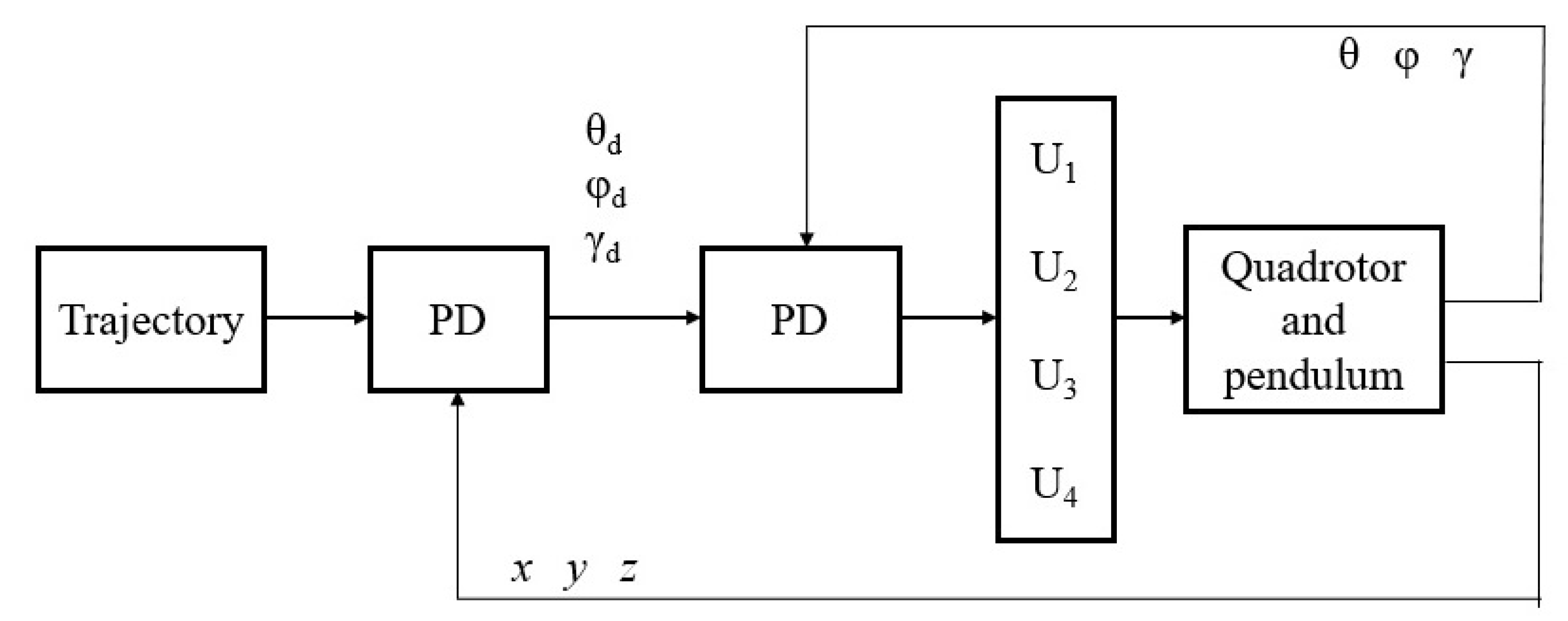
This PD-PD configuration will just count with the ability of path planning and will dispense with pendulum swing rejection. Therefore, this control configuration uses not linearized dynamic equations, described in Section 2. In this case, we get an outer PD in order to calculate the desired angles of the quadrotor, and next, the inner PD loop computes the necessary torques for the quadrotor as in the MPC-PD controller described above. The complete control circuit is shown in Figure 4. The equations to calculate the desired angles are specified in Equations (23) and (24). In Equation (24), x , z refer to the real position of the quadrotor, while x d , z d are the desired position in the assigned trajectory. Their derivatives are obtained by the numerical integration of them. The values of proportional and derivative terms will be detailed in the experiment.
ϕ d = arcsin u z · m U 1 θ d = arcsin u x m U 1 cos ϕ ,
u x = x ¨ d + K D 1 ( x ˙ d x ˙ ) + K P 1 ( x d x ) u z = z ¨ d + K D 1 ( { z ˙ d z ˙ ) + K P 1 ( z d z ) ,
This control configuration is the benchmark that we will use in our experiment to compare against the results of the proposed MPC-PD controller.

4. Experimental Results

4.1. Experimental Setting

A computational experiment based on accurate simulations of the system has been carried out in order to test the efficiency and validity of the model. We compare our MPC-PD control proposal with PD-PD control configuration. The simulation experiment was carried out using a discretization of the time variable and all the simulations cover a time of 32 s, including the transient state of the experiment. The time increment used to compute simulation steps is 0.01 s. Experiments have been coded in house in Matlab. The MPC control horizon is 1 s and the selected integration step is 0.1 s. This is, the control horizon consists of 10 steps.
Dynamic parameters of the quadrotor are assumed as in Table 1. Initial angles of the drone are set to 0. Inner-loop PD controller parameters are computed as described in [53]. For experiments in this paper are set as follows: K P = 130 and K D = 39 , which are the same for MPC-PD and PD-PD control configuration. In the case of PD-PD control configuration, K P 1 and K D 1 values are set to 0.25 and 1.6 , respectively. Thrust of the drone is limited by hardware to 20 N . Drone starting coordinates in the X Z plane are ( 0 , 0 ) .
The control efficiency to follow a path and adjust correctly the quadrotor parameters for the minimization of the double pendulum swing is going to be tested. A parabolic path was planned for the quadrotor to follow. The quadrotor is carrying a double pendulum and both systems are joined by an ideal punctual link. Table 2 gives the parameter setting of the double pendulum. The equation of the parabolic path is z = 2 x 0.066 · x 2 . This parabolic path introduces tangential inertial forces affecting the double pendulum that are not considered in [40]. Double pendulum dynamics during take-off maneuvers from the ground is not considered. Initial values of the pendulum θ 1 and θ 2 are set to 0.

4.2. Results

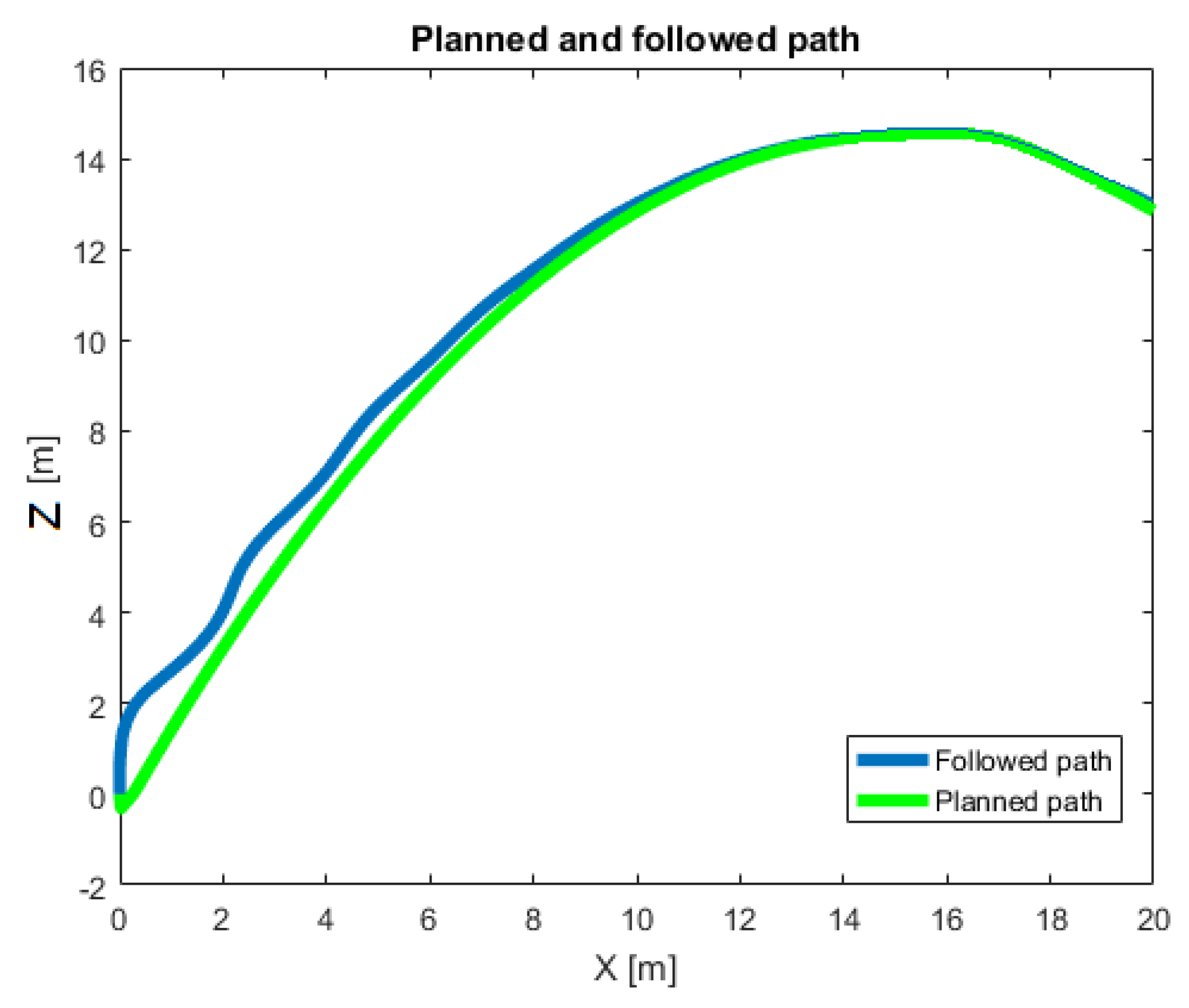
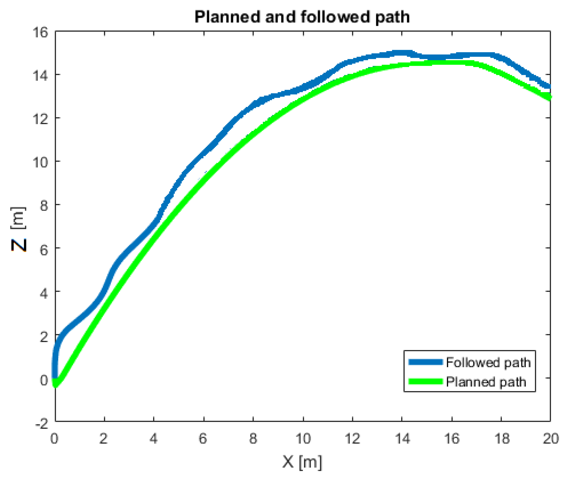
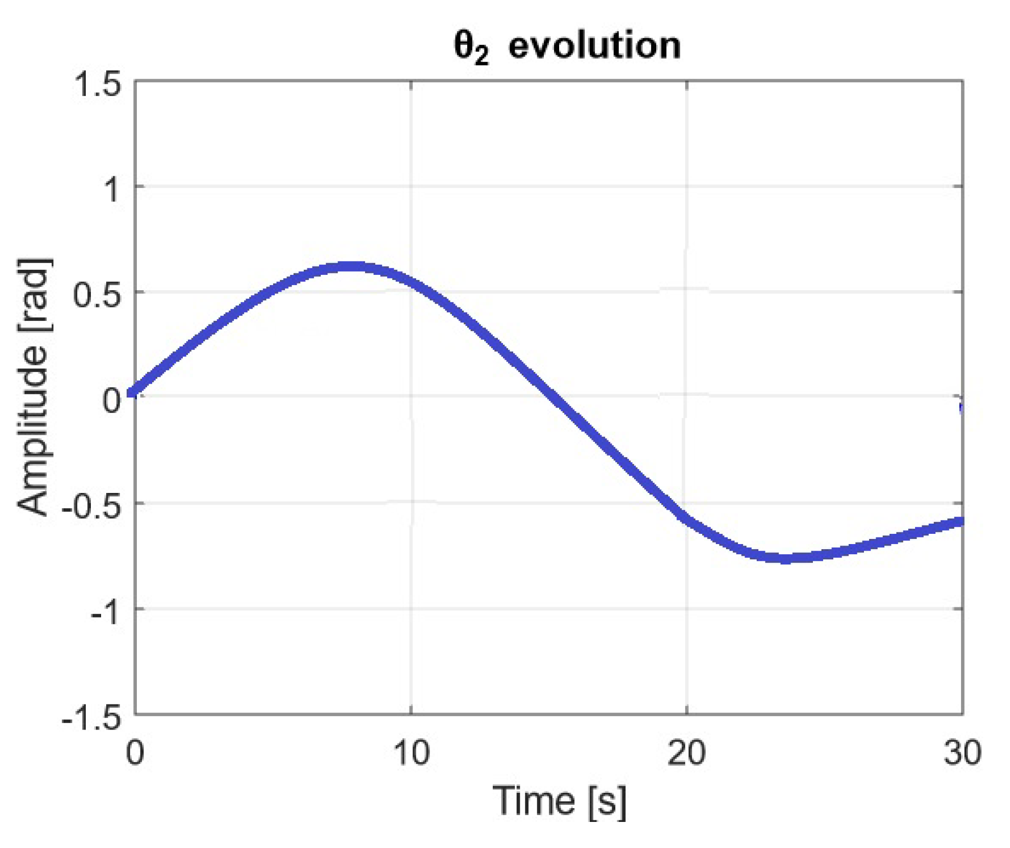
The visual comparison between planned path and the path actually followed by the simulated quadrotor and double pendulum are shown in Figure 5 and Figure 6 for the MPC-PD and the benchmarking PD-PD control systems, respectively. As can be seen, the MPC-PD system achieves highly precise path-following, while the path followed by the PD-PD control system is quite irregular. Figure 7 shows the swing angle of the bottom pendulum mass, θ 2 , along the time of the path achieved by the MPC-PD control system. The maximum value is θ 2 = 0.23 rads. Figure 8 shows the evolution in time of θ 2 under the PD-PD control system. Its maximum value is θ 2 = 0.61 rads. Thus, we achieve a three fold reduction of the double pendulum swinging in the simulated trajectory conditions.
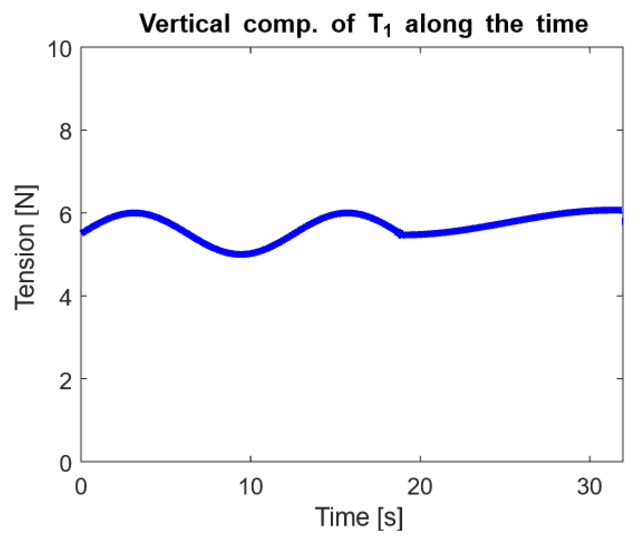
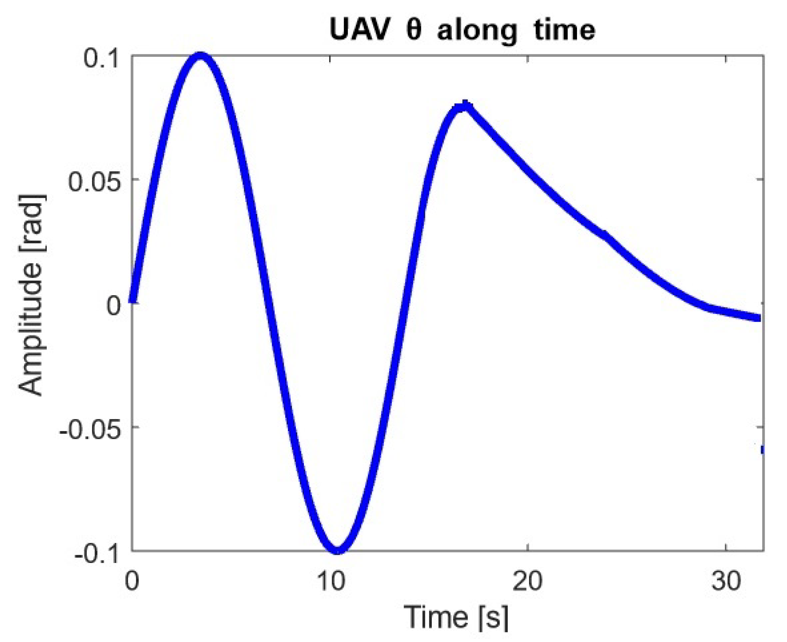
Due to the lack of performance of PD-PD control configuration, in the following we focus on the MPC-PD controller. Figure 9 plots the variation in time of the vertical tension of the first component of the double pendulum, that is, T 1 Z , which represents the tension of the cable attached to the quadrotor and supporting the combined weight of the two particle masses, m 1 and m 2 . Finally, Figure 10 plots the orientation of the quadrotor θ along the simulation time. As we can see, it falls within the maximum and minimum limits defined in Section 3. The quadrotor adopts a changing pitch angle orientation, so that it can compensate the swing of the double pendulum, converging to a stationary hover attitude at the end of the experiment.

5. Conclusions

A system composed of a quadrotor and a double pendulum is a highly nonlinear dynamical system which represents a big challenge to achieve a smooth and precise control performance. The proposed MPC-PC control configuration approach aims to dampen the swing of the double pendulum by the precise and smooth control of the drone orientation. Transporting the pendulum with the least possible oscillations, we can avoid large perturbations affecting the quadrotor and the aggressive increase or decrease of the horizontal and vertical positions of the loads relative to the quadrotor.
The experiment reported in this article validates the proposed control approach for the transportation of a driven double pendulum. Including a comparison against a PD-PD control system configuration. The MPC-PD proposal achieves a three fold reduction of the double pendulum swinging angle. The experiment proved that the quadrotor under MPC-PD control is capable of following the assigned path, despite the variability of T 1 Z and T 1 X . The navigation control is robust enough to stick close to the parabolic planned trajectory (Figure 5). We considered that the most easily perturbable pendulum mass was m 2 , and thus, in Figure 7 we can see that the maximum oscillation has a maximum of about 0.23 rads, and rapidly converges to 0. This stability of the driven double pendulum can also be observed in Figure 9, where T 1 Z is plotted. As each pendulum mass weights 0.3 kg, we see that the vertical component of tension of the cable attached to the drone holds 6 N along the whole trajectory, which means that T 1 X force is almost null and therefore, it encourages the navigation stability of the drone along the path. Therefore, the design of the MPC described in Section 3 proves to be capable of achieving both the swing-free trajectory and the precise navigation along the planned path. Finally, in Figure 10, we can see that the quadrotor manages the double pendulum swing rejection by some compensations in the heading angle, θ . Since we start with the pendulum masses vertically alienated, i.e., θ 1 = θ 2 = 0 , the beginning of the advance of the quadrotor forces the pendulum swing backwards due to inertia, which is compensated by the quadrotor by reducing its heading angle till it overcomes the transient starting regime and thus, making the two pendulum masses swing slowly forward.
In the recent bibliography suggested by the reviewers, we found a quite recent work dealing with the control of a double pendulum transportation, while trying to amortiguate the double pendulum swing [38,39,40]. Specifically, they use classical PID controllers to handle this problem. Contrary to our proposed MPC-PD approach, PIDs can neither include system constraints, nor they can benefit from the robustness of Kalmann filtering. Experimental results in [38,39,40] are quite interesting and we plan future work in order to reproduce their with our MPC-PD control approach. Further work would be directed to test the adaptive behaviour in aggressive maneuvers and include interactions with physical walls for the payload, such as collisions or taking offs.

Author Contributions

Conceptualization, J.E. and M.G.; methodology, J.M.L.-G. and M.G.; software, J.E. and G.G.; validation, J.E.; writing—original draft preparation, J.E.; writing—review and editing, All; funding acquisition, M.G. All authors have read and agreed to the published version of the manuscript.

Funding

This work has been partially supported by FEDER funds through MINECO project TIN2017-85827-P, and project KK-202000044 of the Elkartek 2020 funding program of the Basque Government. This project has received funding from the European Union’s Horizon 2020 research and innovation programme under the Marie Sklodowska-Curie grant agreement No 777720.

Institutional Review Board Statement

Not applicable.

Conflicts of Interest

The authors declare no conflict of interest.

References

  1. Michael, N.; Fink, J.; Kumar, V. Cooperative manipulation and transportation with aerial robots. Auton. Robot. 2011, 30, 73–86. [Google Scholar] [CrossRef] [Green Version]
  2. Tang, S.; Wüest, V.; Kumar, V. Aggressive flight with suspended payloads using vision-based control. IEEE Robot. Autom. Lett. 2018, 3, 1152–1159. [Google Scholar] [CrossRef]
  3. Villa, D.K.; Brandao, A.S.; Sarcinelli-Filho, M. A survey on load transportation using multirotor uavs. J. Intell. Robot. Syst. 2020, 98, 267–296. [Google Scholar] [CrossRef]
  4. Foehn, P.; Falanga, D.; Kuppuswamy, N.; Tedrake, R.; Scaramuzza, D. Fast Trajectory Optimization for Agile Quadrotor Maneuvers with a Cable-Suspended Payload; Robotics Science and System: Cambridge, MA, USA, 2017. [Google Scholar]
  5. Qian, L.; Liu, H.H. Path-Following Control of A Quadrotor UAV With A Cable-Suspended Payload Under Wind Disturbances. IEEE Trans. Ind. Electron. 2019, 67, 2021–2029. [Google Scholar] [CrossRef]
  6. Estevez, J.; Lopez-Guede, J.M.; Graña, M. Quasi-stationary state transportation of a hose with quadrotors. Robot. Auton. Syst. 2015, 63 Pt 2, 187–194. [Google Scholar] [CrossRef]
  7. Bernard, M.; Kondak, K.; Maza, I.; Ollero, A. Autonomous transportation and deployment with aerial robots for search and rescue missions. J. Field Robot. 2011, 28, 914–931. [Google Scholar] [CrossRef] [Green Version]
  8. Zhang, M.; Ma, X.; Chai, H.; Rong, X.; Tian, X.; Li, Y. A novel online motion planning method for double-pendulum overhead cranes. Nonlinear Dyn. 2016, 85, 1079–1090. [Google Scholar] [CrossRef]
  9. Starr, G. Swing-free transport of suspended objects with a robot manipulator. In Proceedings of the 22nd IEEE Conference on Decision and Control, San Antonio, TX, USA, 14–16 December 1983; pp. 1484–1487. [Google Scholar] [CrossRef]
  10. Starr, G. Swing-free transport of suspended objects with a path-controlled robot manipulator. J. Dyn. Syst. Meas. Control 1985, 107, 97–100. [Google Scholar] [CrossRef]
  11. Xian, B.; Wang, S.; Yang, S. An online trajectory planning approach for a quadrotor UAV with a slung payload. IEEE Trans. Ind. Electron. 2019, 67, 6669–6678. [Google Scholar] [CrossRef]
  12. Oshman, Y.; Isakow, M. Mini-UAV altitude estimation using an inertially stabilized payload. Aerosp. Electron. Syst. IEEE Trans. 1999, 35, 1191–1203. [Google Scholar] [CrossRef]
  13. Borky, J.M. Payload technologies and applications for uninhabited air vehicles (UAVs). In Proceedings of the 1997 IEEE Aerospace Conference, Snowmass, CO, USA, 13 February 1997; Volume 3, pp. 267–283. [Google Scholar] [CrossRef]
  14. Trachte, J.; Gonzalez, F.; McFadyen, A. Nonlinear Model Predictive Control for a multi-rotor with heavy slung load. In Proceedings of the 2014 International Conference on Unmanned Aircraft Systems (ICUAS), Orlando, FL, USA, 27–30 May 2014; pp. 1105–1110. [Google Scholar] [CrossRef]
  15. Lee, B.Y.; Lee, H.I.; Yoo, D.W.; Moon, G.H.; Lee, D.Y.; Young Kim, Y.; Tahk, M.J. Study on payload stabilization method with the slung-load transportation system using a quad-rotor. In Proceedings of the Control Conference (ECC), Linz, Austria, 15–17 July 2015; pp. 2097–2102. [Google Scholar]
  16. Tang, S.; Kumar, V. Mixed integer quadratic program trajectory generation for a quadrotor with a cable-suspended payload. In Proceedings of the 2015 IEEE International Conference on Robotics and Automation (ICRA), Seattle, WA, USA, 26–30 May 2015; pp. 2216–2222. [Google Scholar]
  17. Guerrero, M.; Mercado, D.; Lozano, R.; García, C. Passivity based control for a quadrotor UAV transporting a cable-suspended payload with minimum swing. In Proceedings of the 2015 54th IEEE Conference on Decision and Control (CDC), Osaka, Japan, 15–18 December 2015; pp. 6718–6723. [Google Scholar]
  18. Goodarzi, F.A.; Lee, D.; Lee, T. Geometric stabilization of a quadrotor UAV with a payload connected by flexible cable. In Proceedings of the American Control Conference (ACC), Portland, OR, USA, 4–6 June 2014; pp. 4925–4930. [Google Scholar]
  19. Dai, S.; Lee, T.; Bernstein, D.S. Adaptive Control of a Quadrotor UAV Transporting a Cable-Suspended Load with Unknown Mass. In Proceedings of the 53rd IEEE Conference on Decision and Control, Los Angeles, CA, USA, 15–17 December 2014. [Google Scholar]
  20. Carrio, A.; Sampedro, C.; Rodriguez-Ramos, A.; Campoy, P. A review of deep learning methods and applications for unmanned aerial vehicles. J. Sens. 2017, 2017. [Google Scholar] [CrossRef]
  21. Al-Kaff, A.; Armingol, J.M.; de La Escalera, A. A vision-based navigation system for Unmanned Aerial Vehicles (UAVs). Integr. Comput. Aided Eng. 2019, 26, 297–310. [Google Scholar] [CrossRef]
  22. Sadeghzadeh, I.; Abdolhosseini, M.; Zhang, Y.M. Payload drop application of unmanned quadrotor helicopter using gain-scheduled PID and model predictive control techniques. In Proceedings of the International Conference on Intelligent Robotics and Applications, Montreal, QC, Canada, 3–5 October 2012; Springer: Berlin/Heidelberg, Germany, 2012; pp. 386–395. [Google Scholar]
  23. Faust, A.; Palunko, I.; Cruz, P.; Fierro, R.; Tapia, L. Automated aerial suspended cargo delivery through reinforcement learning. Artif. Intell. 2017, 247, 381–398. [Google Scholar] [CrossRef] [Green Version]
  24. Lee, T.; Sreenath, K.; Kumar, V. Geometric control of cooperating multiple quadrotor UAVs with a suspended payload. In Proceedings of the 52nd IEEE Conference on Decision and Control, Firenze, Italy, 10–13 December 2013; pp. 5510–5515. [Google Scholar]
  25. Estevez, J.; Graña, M.; Lopez-Guede, G.J. Online fuzzy modulated adaptive PD control for cooperative aerial transportation of deformable linear objects. Integr. Comput. Aided Eng. 2016, 24, 41–55. [Google Scholar] [CrossRef]
  26. Mellinger, D.; Shomin, M.; Michael, N.; Kumar, V. Cooperative grasping and transport using multiple quadrotors. In Distributed Autonomous Robotic Systems; Springer: Berlin/Heidelberg, Germany, 2013; pp. 545–558. [Google Scholar]
  27. Slegers, N.; Costello, M. Model predictive control of a parafoil and payload system. J. Guid. Control Dyn. 2005, 28, 816–821. [Google Scholar] [CrossRef]
  28. Kang, Y.; Hedrick, J.K. Linear tracking for a fixed-wing UAV using nonlinear model predictive control. IEEE Trans. Control Syst. Technol. 2009, 17, 1202–1210. [Google Scholar] [CrossRef]
  29. Tartaglione, G.; DAmato, E.; Ariola, M.; Rossi, P.S.; Johansen, T.A. Model predictive control for a multi-body slung-load system. Robot. Auton. Syst. 2017, 92, 1–11. [Google Scholar] [CrossRef]
  30. Faust, A.; Palunko, I.; Cruz, P.; Fierro, R.; Tapia, L. Learning swing-free trajectories for UAVs with a suspended load. In Proceedings of the 2013 IEEE International Conference on Robotics and Automation, Karlsruhe, Germany, 6–10 May 2013; pp. 4902–4909. [Google Scholar]
  31. De Crousaz, C.; Farshidian, F.; Neunert, M.; Buchli, J. Unified motion control for dynamic quadrotor maneuvers demonstrated on slung load and rotor failure tasks. In Proceedings of the 2015 IEEE International Conference on Robotics and Automation (ICRA), Seattle, WA, USA, 26–30 May 2015; pp. 2223–2229. [Google Scholar]
  32. Palunko, I.; Fierro, R.; Cruz, P. Trajectory generation for swing-free maneuvers of a quadrotor with suspended payload: A dynamic programming approach. In Proceedings of the 2012 IEEE International Conference on Robotics and Automation, Saint Paul, MN, USA, 14–18 May 2012; pp. 2691–2697. [Google Scholar] [CrossRef]
  33. Zameroski, D.; Starr, G.; Wood, J.; Lumia, R. Rapid swing-free transport of nonlinear payloads using dynamic programming. J. Dyn. Syst. Meas. Control 2008, 130, 041001. [Google Scholar] [CrossRef]
  34. Nicotra, M.M.; Garone, E.; Naldi, R.; Marconi, L. Nested saturation control of an UAV carrying a suspended load. In Proceedings of the 2014 American Control Conference, Portland, OR, USA, 4–6 June 2014; pp. 3585–3590. [Google Scholar] [CrossRef]
  35. Guerrero-Sánchez, M.E.; Mercado-Ravell, D.A.; Lozano, R.; García-Beltrán, C.D. Swing-attenuation for a quadrotor transporting a cable-suspended payload. ISA Trans. 2017, 68, 433–449. [Google Scholar] [CrossRef]
  36. Sadr, S.; Moosavian, S.A.A.; Zarafshan, P. Dynamics modeling and control of a quadrotor with swing load. J. Robot. 2014, 2014. [Google Scholar] [CrossRef]
  37. Choo, Y.i.; Casarella, M.J. A Survey of Analytical Methods for Dynamic Simulation of Cable-Body Systems. J. Hydronautics 1973, 7, 137–144. [Google Scholar] [CrossRef]
  38. Yang, S.; Xian, B. Energy-based nonlinear adaptive control design for the quadrotor UAV system with a suspended payload. IEEE Trans. Ind. Electron. 2019, 67, 2054–2064. [Google Scholar] [CrossRef]
  39. Liang, X.; Zhang, P.; Fang, Y.; Lin, H.; Li, C.; Zhao, X. A Novel Nonlinear Control Scheme for Double-Pendulum Quadrotor Transportation Systems. In Proceedings of the 2019 IEEE/ASME International Conference on Advanced Intelligent Mechatronics (AIM), Hong Kong, China, 8–12 July 2019; pp. 714–719. [Google Scholar]
  40. Liang, X.; Zhang, P.; Fang, Y.; Lin, H.; He, W. Nonlinear Control for Aerial Transportation Systems with Double-Pendulum Swing Effects. IEEE Trans. Ind. Electron. 2020. [Google Scholar] [CrossRef]
  41. Awrejcewicz, J.; Supeł, B.; Lamarque, C.H.; Kudra, G.; Wasilewski, G.; Olejnik, P. Numerical and experimental study of regular and chaotic motion of triple physical pendulum. Int. J. Bifurc. Chaos 2008, 18, 2883–2915. [Google Scholar] [CrossRef]
  42. Butusov, D.; Karimov, A.; Tutueva, A.; Kaplun, D.; Nepomuceno, E.G. The effects of Padé numerical integration in simulation of conservative chaotic systems. Entropy 2019, 21, 362. [Google Scholar] [CrossRef] [PubMed] [Green Version]
  43. Potdar, N.D.; de Croon, G.C.; Alonso-Mora, J. Online trajectory planning and control of a MAV payload system in dynamic environments. Auton. Robot. 2020, 44, 1065–1089. [Google Scholar] [CrossRef]
  44. de Alcantara Andrade, F.A.; Reinier Hovenburg, A.; Netto de Lima, L.; Dahlin Rodin, C.; Johansen, T.A.; Storvold, R.; Moraes Correia, C.A.; Barreto Haddad, D. Autonomous unmanned aerial vehicles in search and rescue missions using real-time cooperative model predictive control. Sensors 2019, 19, 4067. [Google Scholar] [CrossRef] [PubMed] [Green Version]
  45. Jain, R.P.K. Transportation of Cable Suspended Load Using Unmanned Aerial Vehicles: A Real-Time Model Predictive Control Approach. Master’s Thesis, Delft University of Technology, Delft, The Netherlands, 2015. [Google Scholar]
  46. Garriga, J.L.; Soroush, M. Model predictive control tuning methods: A review. Ind. Eng. Chem. Res. 2010, 49, 3505–3515. [Google Scholar] [CrossRef]
  47. Baca, T.; Hert, D.; Loianno, G.; Saska, M.; Kumar, V. Model predictive trajectory tracking and collision avoidance for reliable outdoor deployment of unmanned aerial vehicles. In Proceedings of the 2018 IEEE/RSJ International Conference on Intelligent Robots and Systems (IROS), Madrid, Spain, 1–5 October 2018; pp. 6753–6760. [Google Scholar]
  48. Bemporad, A.; Rocchi, C. Decentralized linear time-varying model predictive control of a formation of unmanned aerial vehicles. In Proceedings of the 2011 50th IEEE Conference on Decision and Control and European Control Conference, Orlando, FL, USA, 12–15 December 2011; pp. 7488–7493. [Google Scholar]
  49. Huang, R.; Patwardhan, S.C.; Biegler, L.T. Robust stability of nonlinear model predictive control based on extended Kalman filter. J. Process Control 2012, 22, 82–89. [Google Scholar] [CrossRef]
  50. Zenere, A.; Zorzi, M. On the coupling of model predictive control and robust Kalman filtering. IET Control Theory Appl. 2018, 12, 1873–1881. [Google Scholar] [CrossRef] [Green Version]
  51. Alexis, K.; Papachristos, C.; Siegwart, R.; Tzes, A. Robust model predictive flight control of unmanned rotorcrafts. J. Intell. Robot. Syst. 2016, 81, 443–469. [Google Scholar] [CrossRef]
  52. Feng, Y.; Zhang, C.; Baek, S.; Rawashdeh, S.; Mohammadi, A. Autonomous landing of a UAV on a moving platform using model predictive control. Drones 2018, 2, 34. [Google Scholar] [CrossRef] [Green Version]
  53. Estevez, J.; Graña, M. Robust control tuning by PSO of aerial robots hose transportation. In Proceedings of the International Work-Conference on the Interplay Between Natural and Artificial Computation, Elche, Spain, 1–5 June 2015; Springer: Cham, Switzerland, 2015; pp. 291–300. [Google Scholar]
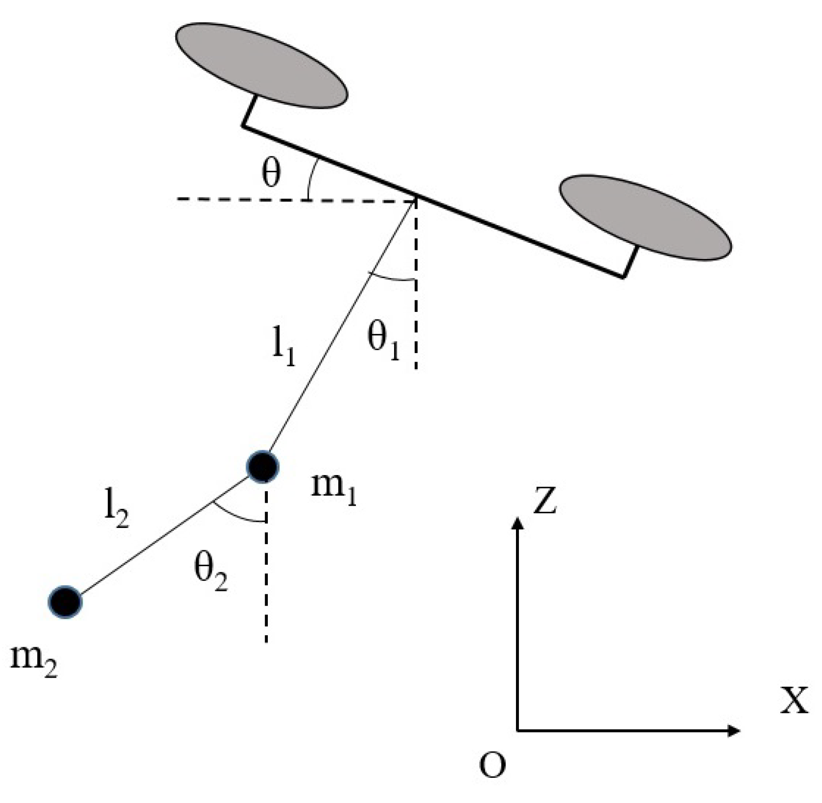
Figure 1. Schematic representation of the drone and double pendulum system in the considered (XZ) coordinate system for double pendulum swing.
Applsci 11 05487 g001
Figure 2. Forces in the double pendulum system.
Applsci 11 05487 g002
Figure 3. MPC-PD Control Configuration of the System.
Applsci 11 05487 g003
Figure 4. PD-PD control configuration of the system.
Applsci 11 05487 g004
Figure 5. Path planned (green) and followed (blue) by the quadrotor in XZ plane under control of the MPC-PD control system.
Applsci 11 05487 g005
Figure 6. Path planned (green) and followed (blue) by the quadrotor in XZ plane under control of the PD-PD control system.
Applsci 11 05487 g006
Figure 7. Swing angle θ 2 of the second pendulum along time achieved by the MPC-PD control system.
Applsci 11 05487 g007
Figure 8. Swing angle θ 2 of the second pendulum along time achieved by the PD-PD control system.
Applsci 11 05487 g008
Figure 9. Vertical tension T 1 of the first pendulum under MPC-PD control.
Applsci 11 05487 g009
Figure 10. Quadrotor θ angle along time under MPC-PD control.
Applsci 11 05487 g010
Table 1. Quadrotor dynamic parameters.
ParameterValue
mass, m1 kg
arm length, l 0.25 m
inertia moments, I x x = I y y 5 × 10 3 [ Nms 2 ]
inertia moment, I z z 1 × 10 2 [ Nms 2 ]
propeller thrust coefficient, b 3 × 10 6 [ Ns 2 ]
drag, d 1 × 10 7 [ Nms 2 ]
Table 2. Driven double pendulum data.
ParameterValue
m 1 , m 2 0.3 kg
L 1 , L 2 0.5 m
Publisher’s Note: MDPI stays neutral with regard to jurisdictional claims in published maps and institutional affiliations.