Article

ResQbot 2.0: An Improved Design of a Mobile Rescue Robot with an Inflatable Neck Securing Device for Safe Casualty Extraction

1
Robot Intelligence Lab, Dyson School of Design Engineering, Imperial College London, London SW7 2AZ, UK
2
Research Center for Electrical Power and Mechatronics, Indonesian Institute of Sciences—LIPI, Bandung 40135, Indonesia
3
Department of Mechanical Engineering, Imperial College London, London SW7 2AZ, UK
4
London Ambulance Service NHS Trust, London SE1 8SD, UK
*
Author to whom correspondence should be addressed.
Website: https://www.imperial.ac.uk/robot-intelligence/robots/resqbot/ (accessed on 15 May 2021).
Appl. Sci. 2021, 11(12), 5414; https://doi.org/10.3390/app11125414
Submission received: 18 May 2021 / Revised: 2 June 2021 / Accepted: 7 June 2021 / Published: 10 June 2021
(This article belongs to the Special Issue Innovative Robot Designs and Approaches)

Abstract

:
Despite the fact that a large number of research studies have been conducted in the field of search and rescue robotics, significantly little attention has been given to the development of rescue robots capable of performing physical rescue interventions, including loading and transporting victims to a safe zone—i.e., casualty extraction tasks. The aim of this study is to develop a mobile rescue robot that could assist first responders when saving casualties from a dangerous area by performing a casualty extraction procedure whilst ensuring that no additional injury is caused by the operation and no additional lives are put at risk. In this paper, we present a novel design of ResQbot 2.0—a mobile rescue robot designed for performing the casualty extraction task. This robot is a stretcher-type casualty extraction robot, which is a significantly improved version of the initial proof-of-concept prototype, ResQbot (retrospectively referred to as ResQbot 1.0), that has been developed in our previous work. The proposed designs and development of the mechanical system of ResQbot 2.0, as well as the method for safely loading a full-body casualty onto the robot’s ‘stretcher bed’, are described in detail based on the conducted literature review, evaluation of our previous work, and feedback provided by medical professionals. We perform simulation experiments in the Gazebo physics engine simulator to verify the proposed design and the casualty extraction procedure. The simulation results demonstrate the capability of ResQbot 2.0 to carry out safe casualty extractions successfully.

1. Introduction

Responses to natural or human-made disasters—such as chemical, biological, radiological, and nuclear (CBRN) incidents—are always a race against time. Extracting casualties from a hazardous scene is such an example of an emergency case in which a significant amount of pressure and risk is placed on the people working as the first responders. Efficient and timely action is crucial since it is known that the mortality rate increases and reaches a peak after 48 h, implying that the chance of survival drops significantly after this period [1,2,3,4,5]. While it is crucial to act fast, ensuring the rescue operation is safely performed is also critical. Apart from ensuring the safety of the first responders, minimising the possibility of creating further damage or additional risk to the casualties is a high priority [5].
Currently, research and development in robotics and its applications is an actively growing field, including the development of robotics applications in assisting first responders in rescue missions, in which the main objective is to improve the search and rescue (SAR) operation to become faster and safer. A wide range of robotics design has been introduced and deployed for specifically performing SAR missions [4,5,6,7,8,9,10,11]. Most of these robots are designed to assist with some specific tasks that can be grouped into four general categories according to their purpose in the SAR response process, namely search, extraction, evacuation, and treatment [5].
The field of search robotics has received the most attention so far, particularly unmanned aerial vehicles (UAVs), which have been used in many rescue operations [12,13,14,15,16,17,18], collecting evidence about the position of a missing person, but not interacting with the casualty. However, the field of casualty extraction using rescue robots is significantly less mature, with fewer applicatFions and proposed designs. The main reason for this is that these robots are often significantly larger and more complex due to the medical casualty handling requirements [9]. Other than academic institutions, most of the research and many technical implementation proposals were carried out by military organisations [6].
This paper presents a novel design of a mobile rescue robot, called ResQbot 2.0, capable of safely rescuing a casualty lying on the ground (i.e., casualty extraction procedure). This robot design is a significantly improved version of the initial proof-of-concept prototype—ResQbot (retrospectively referred to as ResQbot 1.0)—that has been developed in our previous work, and has been presented in [19,20,21,22,23]. The main contributions of this work can be summarised as follows:
(1)
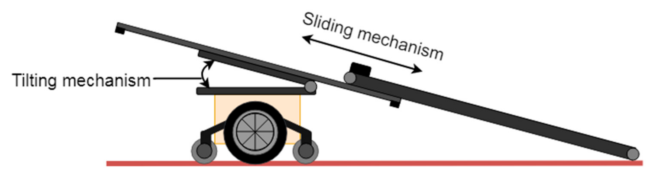
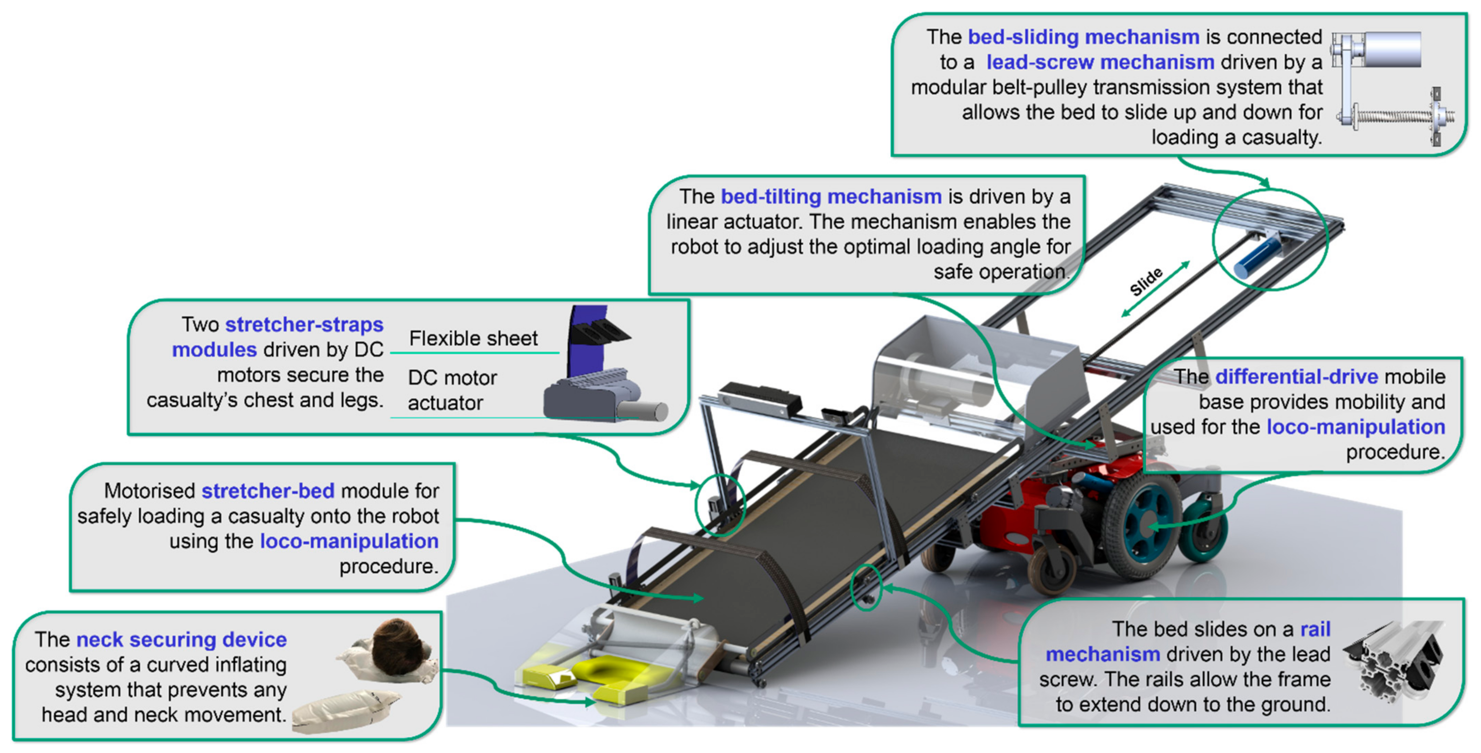
The novel ResQbot 2.0 design comprises seven main novel components: A differential-drive mobile base; a stretcher bed tilting mechanism; a stretcher bed sliding mechanism; a motorised stretcher bed conveyor module, a pair of motorised stretcher strap modules; and a neck securing device module.
(2)
The proposed methodology of casualty extraction procedure using ResQbot 2.0 for safely loading a full-body casualty onto the robot’s ‘stretcher bed’.
(3)
Validation of the proposed design and the casualty extraction procedure via simulation experiments in the Gazebo physics engine simulator.
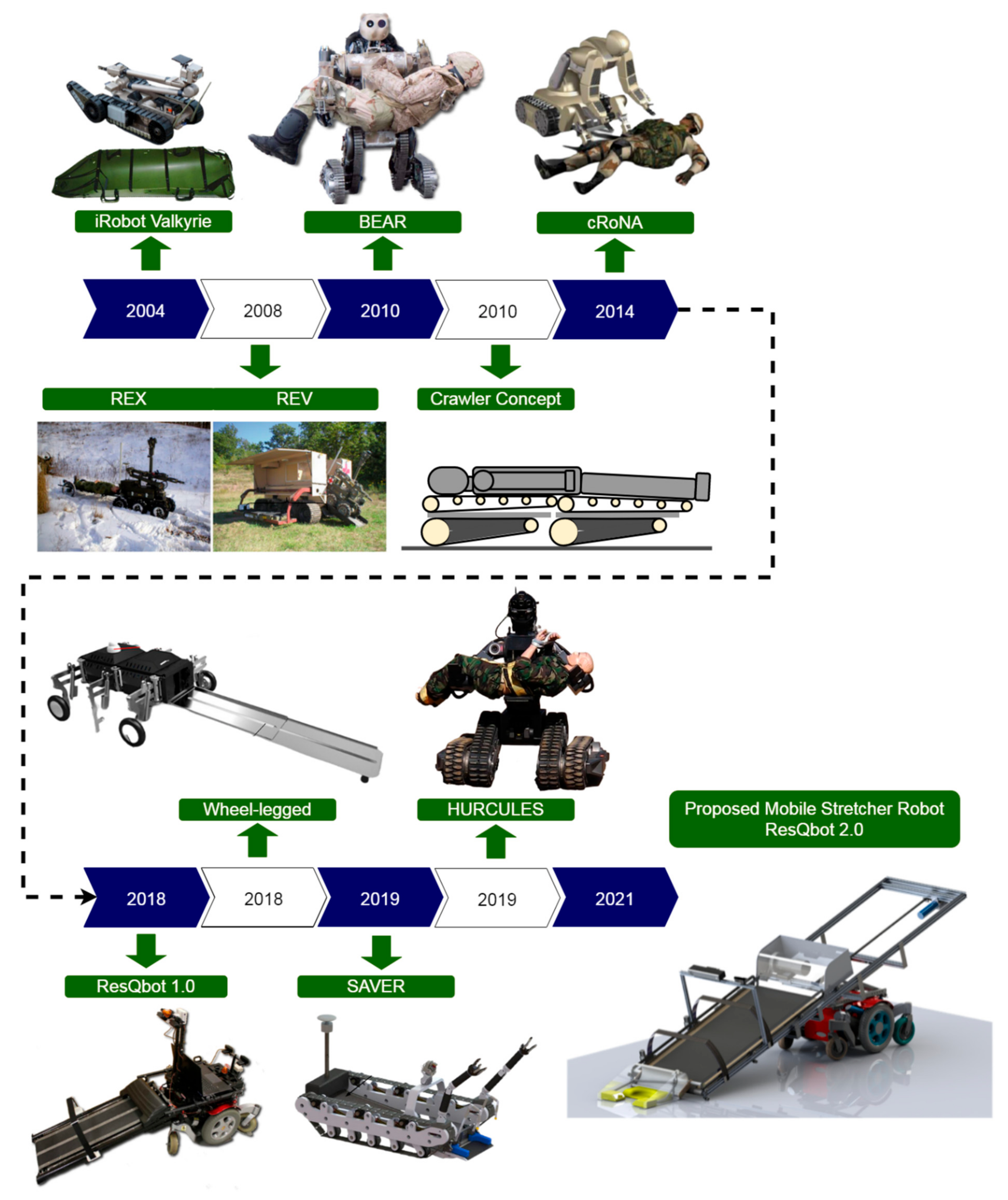
The remaining of this paper is organised as follows: In Section 2, we review the state of the art on the major work related to the existing mobile rescue robots designed for casualty extraction. In Section 3, we describe the design specification and development of the robot, as well as the medical and safety considerations. The proposed robot design and method of casualty extraction procedure using the proposed robot design are described in Section 4. Furthermore, the results and discussion of the proposed design are presented in Section 5. Finally, we conclude our findings in Section 6.

2. Related Work

In this section, we present an overview of the existing mobile rescue robots designed for casualty extraction. The summary of major contributions to the field of casualty extraction is depicted in Figure 1 [23,24,25,26,27,28,29,30,31].
One of the very first casualty extraction proposal incorporating a mobile robot is the iRobot Valkyrie project, as presented in [26,32]. In this proposal, the idea is implementing a flexible stretcher that is tethered to a multi-purpose mobile robot (see Figure 1, iRobot Valkyrie [24]). First, an operator or medic is remotely operating the robot to find the casualty. Then, the casualty needs to roll with its own strength onto the stretcher. After the casualty rolls safely on the stretcher, the robot then pulls away the stretcher to the safe place for further treatment [26].
The US Department of Defence then introduced the robotic extraction (REX) and robotic evacuation (REV) rescue robot system for casualty extraction missions as presented in [25]. This system combines several differently-sized, unmanned ground vehicles (UGV) to perform a rescue mission. A small, mobile manipulator (REX) is used for short-range extraction from the site of injury to a larger and faster vehicle (REV), which transports the casualty to a medical facility (see Figure 1, REX and REV). The system is part of a more extensive tactical amphibious ground support system (TAGS). This project was proposed to extract battlefield casualties from hostile environments and from under fire, designed mainly for outdoor battlefield terrain [6].
One of the most sophisticated robot platforms designed and developed specifically for casualty extraction procedures is a robot with a semi-humanoid design. The humanoid robot is roughly the size of a human male. Its upper torso is equipped with a heavy-duty dual-arm manipulator built on top of a mobile base with tank tracks on its thighs and calves. The battlefield extraction assist robot (BEAR) developed by Vecna Technologies [6,7], the combat robotic nursing assistant (cRoNA) [8] from Hstar Technologies [33], and the humanoid rescue robot for calamity response (HURCULES) robot [29] developed by the Agency for Defense Development, South Korea [34,35] are examples of a semi-humanoid form mobile robot platform, designed and developed specifically for casualty-extraction procedures (see Figure 1, BEAR, cRoNA, HURCULES). Compared to all previous designs, these robots are designed to be highly agile while performing casualty extraction using their arms by scooping, lifting up, and carrying the casualty (see Figure 2a). While this casualty extraction procedure seems to be flexible, feasible, and mimics how a normal person handles a casualty, medical safety remains an unsolved issue as this design does not stabilise the sensitive areas, including the casualty’s spine, neck, and head.
In [29], the authors highlight that one of the noticeable features in the mechanical design of the HURCULES robot is to use the worm gear in the joint to maintain the safety of the casualty even with the power off and to reduce the energy through a selected operating mode. Moreover, unlike the upper body of a conventional humanoid robot, a chest plate is installed and used to properly distribute the casualty’s weight to the dual-arm manipulator and the chest plate when carrying the casualty. Nevertheless, the lack of body support (especially spine, neck, and head) during the procedure, in comparison to the conventional stretcher, remains a critical concern. In addition, in terms of operating the robots, controlling such complex robots performing intricate and sensitive tasks is a significant challenge. Teleoperating such a complex system most likely requires more than one highly skilled and experienced operator with complex teleoperation devices.
Alternative designs using stretcher-type constructions or litters that aim for a smoother pick-up and transportation process of casualty extraction procedure have also been investigated. Examples of proposals for such systems are the robot presented by Iwano et al. in [36,37,38] and the Tokyo Fire Department [39]. These robots are designed to perform casualty extraction using a conveyor belt mechanism to pick up a casualty without having to move the body significantly in the process. Once the casualty is properly loaded on top of the robot, the conveyor belt base then properly supports the casualty’s body so it can additionally serve as a stretcher bed. Thus, this robot design and method for casualty extraction is expected to be safer and would minimise the possibility of causing additional injuries to the casualty during the casualty extraction process.
Ning in [28] has also presented a similar design of a stretcher-type casualty ex-traction robot. A unique feature of this design is that it incorporates a wheel-legged structure that can be raised or lowered using linear actuators. The purpose of the design is to improve the robot’s adaptability in a complex disaster scene. On the other hand, a very recently published work in [30,40] presents a casualty extraction robot design called semi-autonomous victim extraction robot (SAVER) [41,42]. This robot is equipped with two manipulator arms and a head support system. The arms are designed for the telemanipulation process to gently adjust the pose of the casualty prior to the loading process. The head support system is designed to grasp the injured person and stabilise the head and neck while gently pulling the casualty on board.
In our previous works presented in [19,20,21,22,23], we have developed a proof-of-concept mobile rescue robot for casualty extraction, called ResQbot (see Figure 1, ResQbot 1.0). This robot is a stretcher-type mobile rescue robot designed to safely load a casualty using the loco-manipulation approach [23] that uses a combination of the robot’s wheeled locomotion and the belt conveyor mechanism to load a casualty (i.e., manipulation task), as illustrated in Figure 2b. The loco-manipulation approach allows the robot to load the casualty while ensuring that key safety thresholds (based on [43,44]) are adhered to and avoiding potential causes of additional injury to the casualty, such as head, neck or spinal cord injuries [23]. The stretcher bed conveyor of this robot is also equipped with a stretcher strap mechanism to safely secure the casualty during transportation.
Despite the promising results obtained from the evaluation experiments on the loco-manipulation approach using ResQbot 1.0 [23], ResQbot 1.0 is only capable of securing half the body of the casualty (i.e., upper body) onto the robot’s stretcher bed module (see Figure 3a). During the casualty extraction mission, the robot will drag the casualty’s legs during transportation (Videos of ResQbot 1.0 are available at https://www.imperial.ac.uk/robot-intelligence/robots/resqbot/ (accessed on 15 May 2021)). Even though we believe that in an emergency, this procedure is still highly acceptable—in fact, first responders also frequently perform the same procedure [45,46,47]—this procedure could potentially cause severe damage to the casualty.
Another critical concern on the ResQbot 1.0 design is the fact that the loading process, as part of the casualty extraction routine, is initiated from the head of the casualty. Based on the experimental evaluations, the process can satisfy the safety metric (we refer readers to [19,23] for more details about the experiments). Nevertheless, the process (i.e., initiating loading the casualty from the head) is still raising a safety concern in terms of potential damage to the casualty’s head and neck during the initial contact between the robot and the casualty’s head (see Figure 3b).

3. Design Specification

3.1. Design Objectives

The design specification is based on the literature review, evaluation of our previous work, and feedback provided by medical professionals. Based on our previous work, there are at least two main concerns: ResQbot’s inability to safely load the casualty’s entire body and safety regarding the robot’s initial contact with the casualty’s head during casualty extraction procedures. Therefore, in this study, we focus on three main design objectives:
  • Optimising the design mechanism to safely load a casualty’s entire body onto the robot’s stretcher bed.
  • Designing a mechanism that provides more protection to the casualty’s head and neck during the extraction process.
  • Optimising the robot’s compact design and manoeuvrability in narrow environments.

3.2. Design Assumptions

In order to limit the scope of this work, the following assumptions about the robot’s deployment environment were made at the start of the design process:
  • The robot would be working in an urban environment with flat surfaces. Some possible scenarios include areas of gas leaks and radiation/chemical contamination.
  • The robot would not have to deal with stairs.
  • The casualty would be lying flat with hands at the sides (in readiness for loading the casualty onto the robot).
  • The methodology for controlling the ResQbot 2.0 platform (e.g., teleoperation or autonomous modes) lies beyond the scope of this paper.

3.3. Medical Considerations and Research

As mentioned in the introduction, one of the main priorities in casualty extraction procedures is to ensure minimal harm or risk. One of the main design considerations is to minimise any possible traumatic injuries during the casualty extraction procedure. Any unfavourable handling might aggravate injuries, particularly to the neck, head, and spinal cord (which includes the cervical spine). For this reason, medical professionals were consulted during all design stages of ResQbot 2.0, and a survey of the literature was carried out [48,49,50,51,52,53,54,55,56,57].
According to our literature review, it was found that spinal cord injuries and unstable fractures are some of the major concerns. Such injuries can occur either at the tetraplegic (the neck region) or paraplegic level (lower back region) [48,49,50,51,52,53,54,55,56,57]. Injuries at the tetraplegic level can cause impairment or loss of motor or sensory functions in the cervical segments of the spinal cord, affecting arms and legs [48]. To avoid this type of injury, any additional backward (hyperextension) or forward (hyperflexion) bending of the neck, as well as compression or rotation must be avoided [48]. To prevent potential paraplegic traumas, any forward or backward bending of the lower back must also be avoided, although this is less critical.
Possible existing injuries must be taken into account when performing a casualty extraction, especially the possibility of secondary spinal cord injuries, including neurogenic shocks, post-traumatic ischemia or failure to stabilise and immobilise an unstable fracture, which might cause bone fragments to move towards, put pressure on or cut the spinal cord [48]. One of the standard operating procedures is to place the cervical spine in a neutral position and attach a stabilisation unit to the patient, as proposed in [30]. The main objective of this procedure is to minimise translation and rotation of the head in order to avoid the aggravation of spinal injuries during lifting or transportation. In classical ambulant care, post-trauma stabilisation usually includes fitting a cervical collar to the patient’s neck as a frame to immobilise the head. However, recent work has illustrated that a cervical collar is not indispensable, and might even restrict a patient’s airway [50,51]. Therefore, cranio-thoracic stabilisation methods, such as sandbags or stabilisation blocks that maintain the cervical spine straight without a cervical collar [52,53], have received increased attention.
Another safety consideration related to casualty extraction procedures, as shown in Figure 2b and Figure 3b, is the possibility of head injury during contact between the robot and the casualty’s head. A number of research studies have focused on evaluating and developing methods and technical devices that could protect against both spinal cord and head injuries [43,44]. In [43], Engsberg presents an investigation into the possible spinal cord and head injuries caused by an impacting force. This study evaluates several impact-testing methods as well as a selection of injury threshold limits. In a separate study, EURailSafe [44] presented a report on the evaluation of bot head and neck injuries, including injury mechanisms, criteria, and tolerance levels. We used the data from [43,44] to obtain the key safety thresholds and validate our design results.

4. Proposed Design and Method

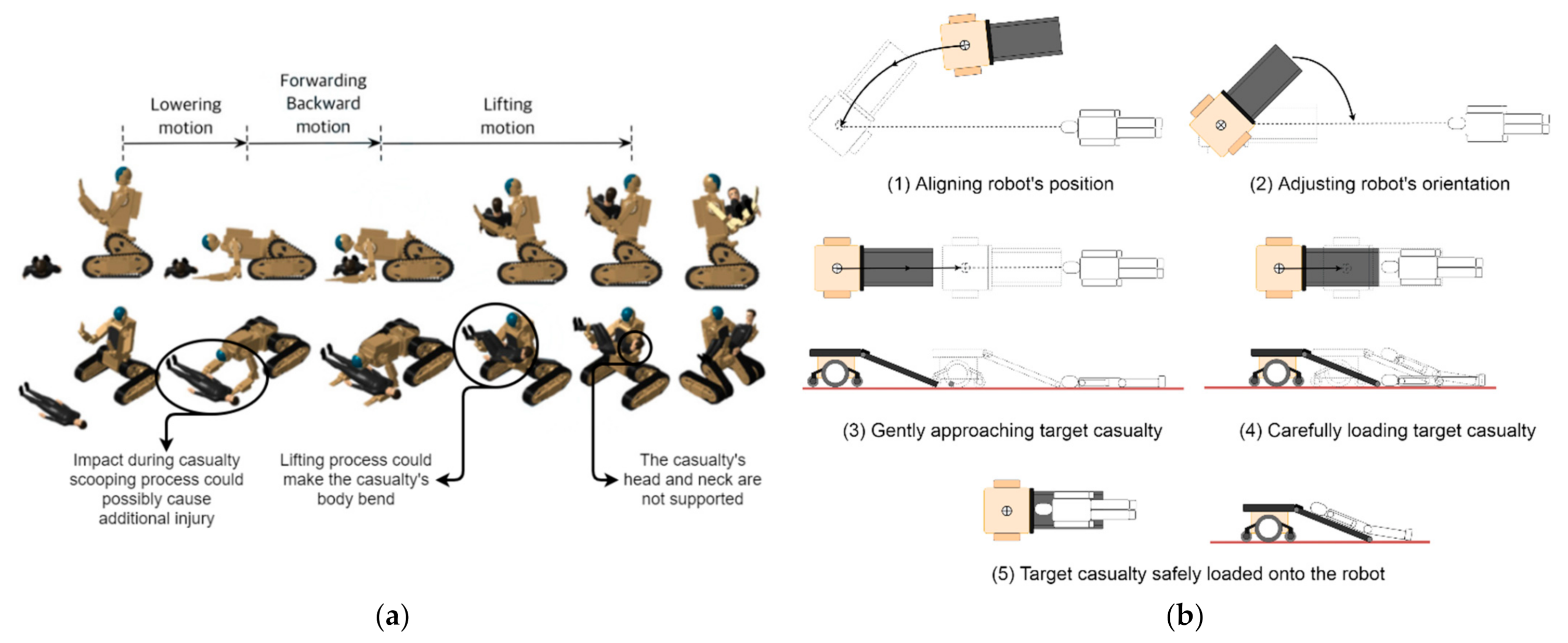
4.1. Proposed Method and Design for Casualty Loading

In this study, we adopted the loco-manipulation approach presented in our previous work [23] for the casualty extraction method. This method was evaluated in the study presented in [19,23]; it has shown potential for the safe loading of casualties and satisfies several safety measures [43,58]. One of the objectives of this study is to propose a robot design to safely load an average-size person’s entire body onto the robot’s stretcher bed and secure it safely.
In order to achieve this objective, the size of the robot’s stretcher bed and conveyor must be increased. This increase in length would lead to an increase in the overall size of the robot. Figure 4a,b illustrates the different robot sizes. The size of the stretcher bed can be increased without a significant change to the robot’s design. There are at least two major problems with this design: (1) The robot’s overall length increases by 1.5 times the length of the original ResQbot 1.0. This will cause the robot to struggle while manoeuvring in typical indoor environments, and (2) the more extended stretcher bed module (potentially loaded with a casualty) towed behind the differential-drive mobile base would make it difficult to manoeuvre the robot and keep the stretcher bed stable, since the mobile base would require much more effort to turn with an asymmetrical load towed behind the mobile base. Moreover, slight turns by the mobile base would cause much more movement on the stretcher bed, making it challenging to keep the stretcher bed stable during transportation.
Figure 4c illustrates the ideal position of the stretcher bed on the mobile base. In this position, the load would be uniformly distributed to the robot’s mobile base. In comparison with the original ResQbot 1.0 configuration (Figure 4a), upgrading the robot’s stretcher bed size would result in a similar overall length when configured as shown in Figure 4c. Moreover, since the robot’s configuration in Figure 4c is symmetrical, the mobile base’s manoeuvrability will be improved seeing as it is a mobile base with a differential-drive wheel mechanism with the driving wheel placed in the middle. Consequently, the stretcher bed would be more stable while manoeuvring the robot during transportation—even when loaded with a casualty.
To accommodate the configuration shown in Figure 4c and retain the robot’s loco-manipulation capability to load the casualty, we propose adding tilting and sliding mechanisms to the stretcher module on the mobile base platform. Figure 5 illustrates the stretcher bed sliding and tilting mechanisms proposed for ResQbot 2.0.
With these additional mechanisms, ResQbot 2.0 could perform casualty extraction in a similar manner to ResQbot 1.0, but with a slightly modified procedure. Figure 6 illustrates the proposed new casualty extraction procedure using ResQbot 2.0.
This procedure involves several major phases:
(1)
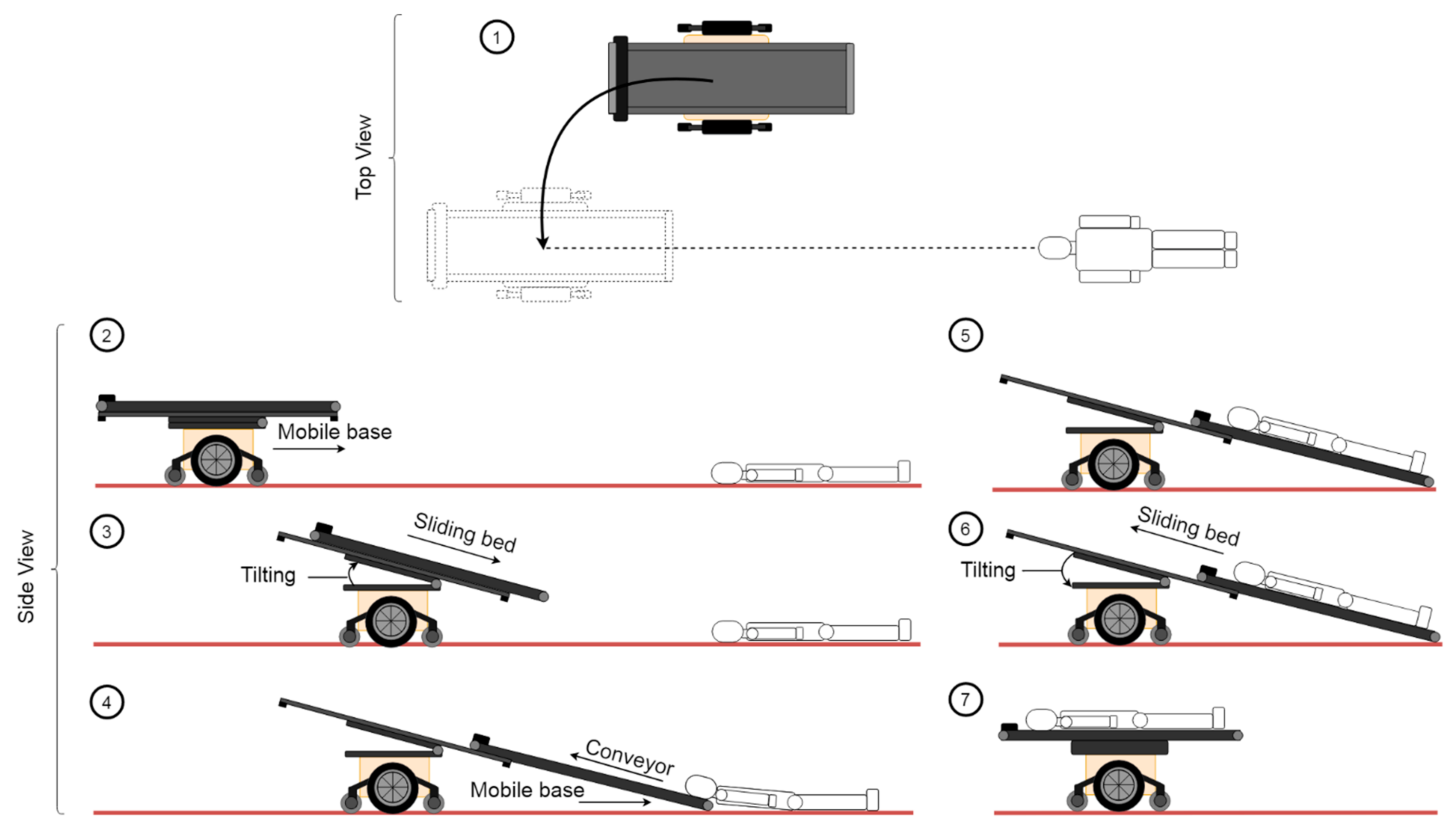
Relative pose adjustment: The robot aligns its relative pose with respect to the victim in preparation for the loco-manipulation routine.
(2)
Approaching the target casualty: The robot gently and safely approaches the casualty and makes contact with the casualty’s head to initiate loading.
(3)
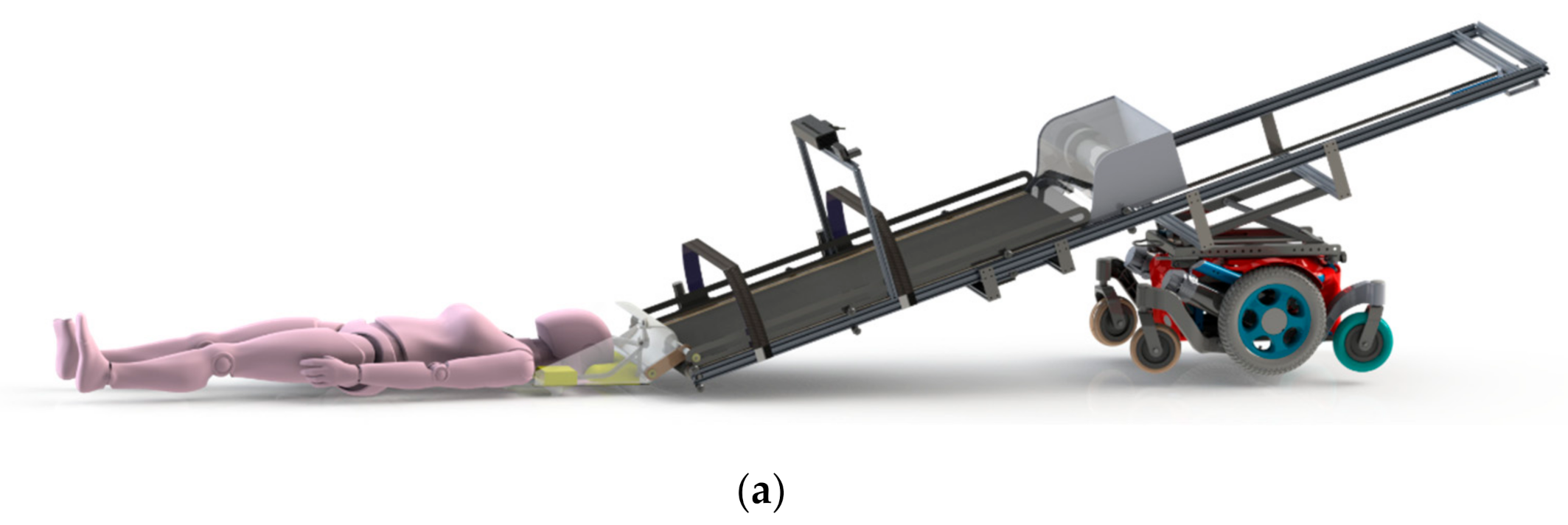
Changing to the loading configuration (i.e., sliding and tilting the stretcher bed): The robot’s stretcher bed frame tilts up to the desired loading angle and then slides down until it touches the ground in readiness to load the casualty.
(4)
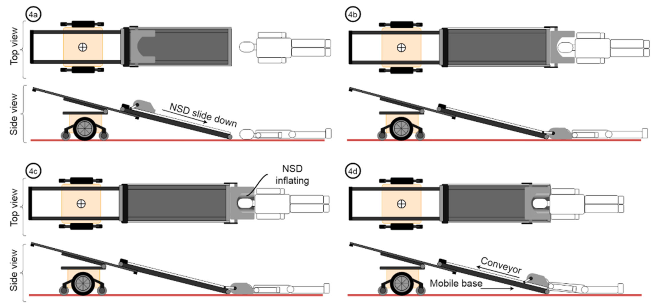
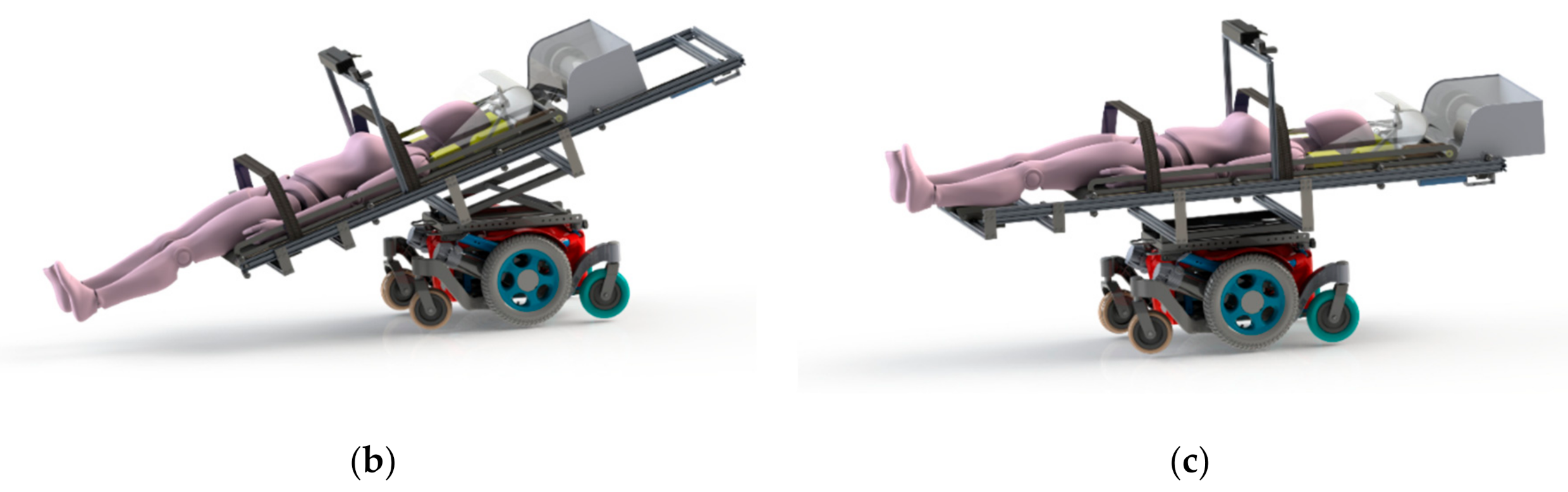
Loading the target casualty: By balancing the movement of the base and the motion of the belt conveyor, the robot smoothly loads the casualty onboard.
(5)
Fastening the stretcher strap: Once the casualty is fully onboard, the strapping mechanism secures, stabilises, and immobilises the casualty, minimising the risk of additional harm due to undesired movements.
(6)
Changing to the compact configuration: Once the casualty is properly secured, the stretcher bed slides up and tilts down to its original compact configuration.
(7)
Transportation: The robot is now ready for the transportation phase. The casualty is brought to the medical area for further treatment.

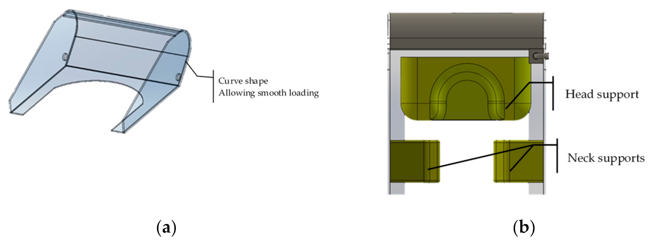
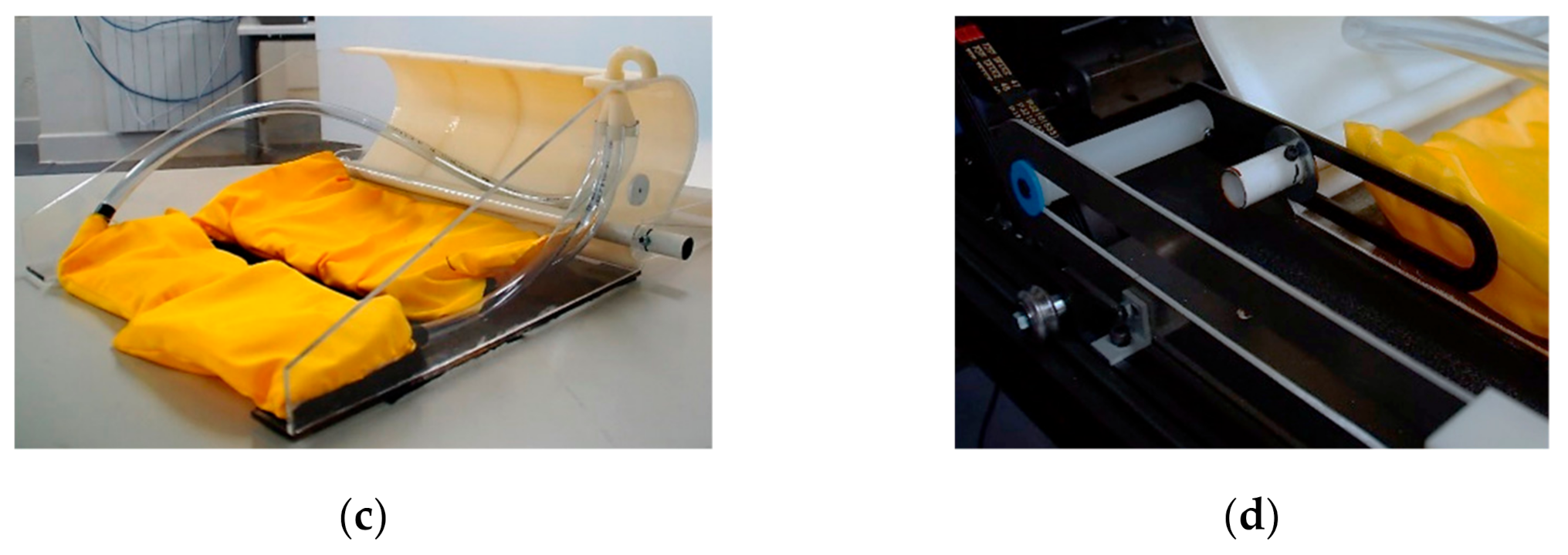
4.2. Neck Securing Device

Another critical concern about the ResQbot 1.0 design is the loading process, which begins with the casualty’s head. In our previous work, presented in [19,23], we deemed the process to be safe and to satisfy the safety metrics, based on the experimental evaluations (we refer readers to [19,23] for more details on the experiments). Nevertheless, this process still raises safety concerns in terms of potential damage to the casualty’s head and neck upon initial contact (see Figure 2b).
To address this safety issue, we propose a novel neck securing device (NSD) as a new safety feature of ResQbot 2.0, which required a new and innovative design. The main purpose of the NSD module is to properly secure the neck and critical parts of the head to avoid excessive bending of the cervical spine and hard impact during loading. We propose an NSD that uses inflatable material. There are at least two main works (see Figure 7a,b) that inspired our design of the inflatable NSD module. In [30,40], the authors proposed a head support system for the SAVER robot designed to grasp the injured person and stabilise the head and neck while gently pulling the casualty onboard. This mechanical system comprises a linear actuator, a tension spring, a string-rigged pulley differential mechanism, and a pair of head pads. The string-rigged pulley differential mechanism is a device that connects the head support pads in order to apply force equally to the right and left sides of the head. Each pad can assume an asymmetric final position, which gives the device the ability to stabilise the head and neck in the position in which the patient is originally encountered. The tension string minimises discomfort and allows a safe and stable hold while restricting the motion of the head. The concept for this head support mechanism is shown in Figure 7a.
Inflatable systems such as airbags and life jacket mechanisms were investigated for possible implementation in the proposed NSD system. The Hovding inflatable cycling helmet presented in [59,60] is one of the inflatable systems considered for the proposed NSD system. It has a collar that is worn around the neck that inflates when sensors indicate that a crash has occurred. Another option is the work presented in [61], which shows various inflatable objects that can be fabricated by the Printflatables platform.
This work combines the design concept inspired by [30,40] and the inflatable object technology shown in [59,61] to develop the NSD for ResQbot 2.0. Figure 7c illustrates the proposed concept, which uses inflatable material. We investigated several designs, all with the same fundamental concept that the inflatable device should cover and surround the casualty’s head and neck up to the shoulders, as illustrated in Figure 7c.
The requirement for the integration of the NSD in the stretcher bed (belt conveyor) system was that the NSD should be able to slide down along the bed to the ground and slide back up around the bed end. The NSD does not require a separate actuator for the sliding movement. The movement of the NSD relies on friction between the NSD and the conveyor belt. The NSD is placed on top of the conveyor and attached to linear guides on both sides of the NSD to constrain its movement only along the stretcher bed. Figure 8 illustrates the updated procedure to load casualties by means of the NSD system. This procedure is an extension of Step 4 in Figure 6.

5. Results and Discussion

5.1. ResQbot 2.0 Design Results

Figure 9 shows the final CAD design for ResQbot 2.0—a novel mobile robot stretcher bed with an inflatable neck securing device. ResQbot 2.0 consists of six main modules:
  • A differential-drive mobile base that provides mobility and flexible manoeuvrability in typical urban and indoor terrains.
  • A stretcher bed tilting module that enables ResQbot 2.0 to adjust the optimal loading angle for safe casualty extraction procedures. This module is driven by a linear actuator, and a bar linkage mechanism adjusts the bed’s tilting angle.
  • A stretcher bed sliding module that enables the robot’s stretcher bed to slide up and down in order to switch between the loading configuration (for loading a casualty) and the compact configuration (for general robot navigation and casualty transportation). This module consists of rail mechanisms at both sides of the robot’s stretcher bed that allow the bed to slide smoothly along its frame and a lead-screw mechanism that drives the bed’s linear movement.
  • A motorised stretcher bed conveyor module is essential in order to enable ResQbot 2.0 to gently load a casualty by synchronising the conveyor belt’s loading movement with the movement of the mobile base (see the loco-manipulation approach presented in [19,23]).
  • A pair of motorised stretcher strap modules that enable ResQbot 2.0 to secure, stabilise, and immobilise the casualty on the robot’s stretcher bed in order to prevent any undesired movement that could cause additional harm to the casualty.
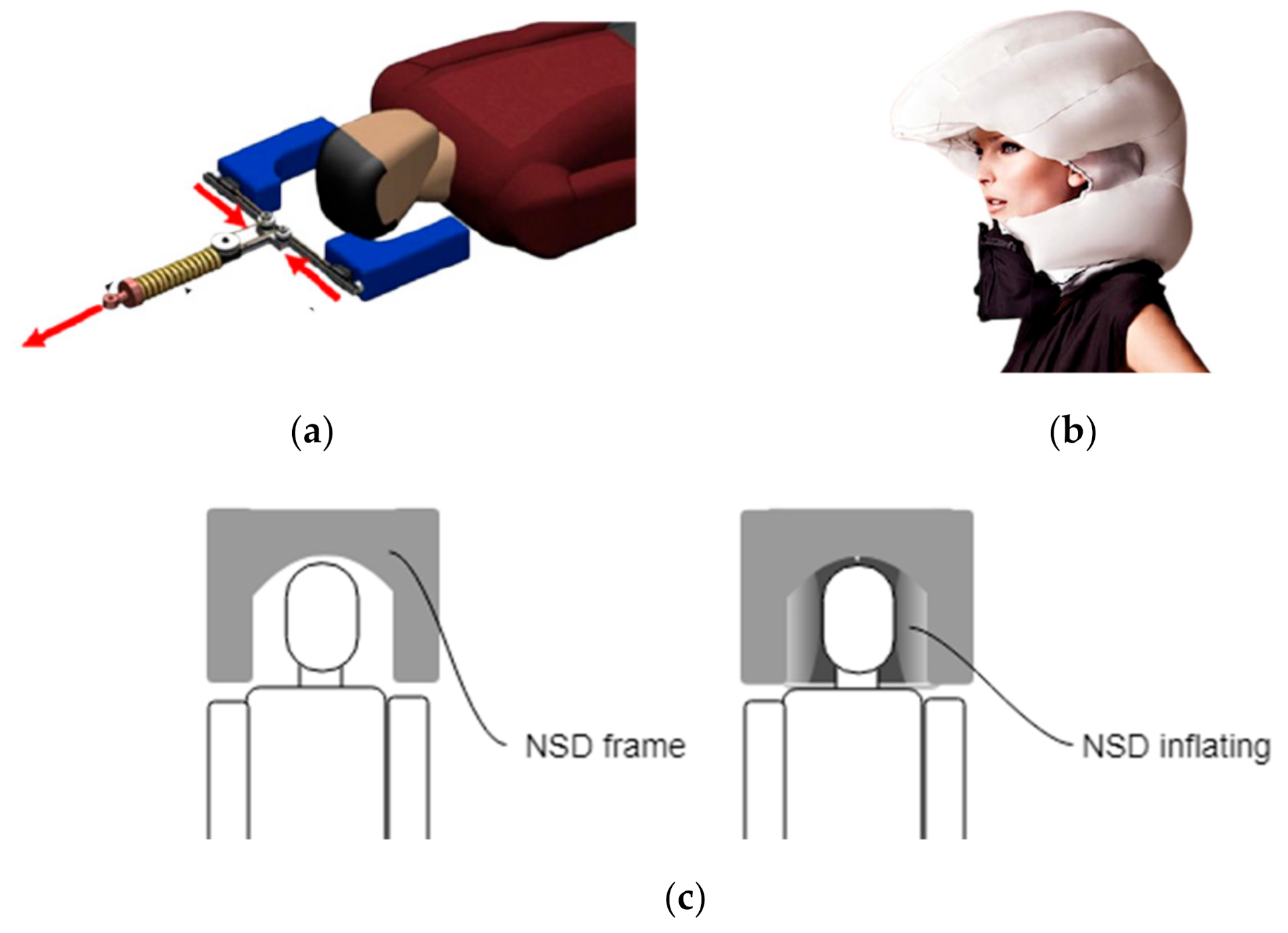
  • A neck securing device module that consists of a rigid frame and several components that inflate and surround the casualty’s head and neck up to the shoulders in order to prevent any undesired impact during the casualty loading procedure. It also stabilises and immobilises the casualty’s head and neck during the extraction process.

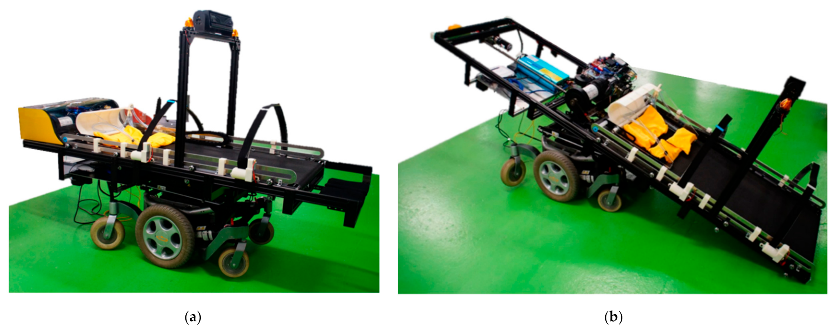
5.2. The ResQbot 2.0 Assembly

Figure 10 shows the fully assembled ResQbot 2.0 in the compact (Figure 10a) and loading configurations (Figure 10b). In the following subsections, we discuss each main module and mechanism.

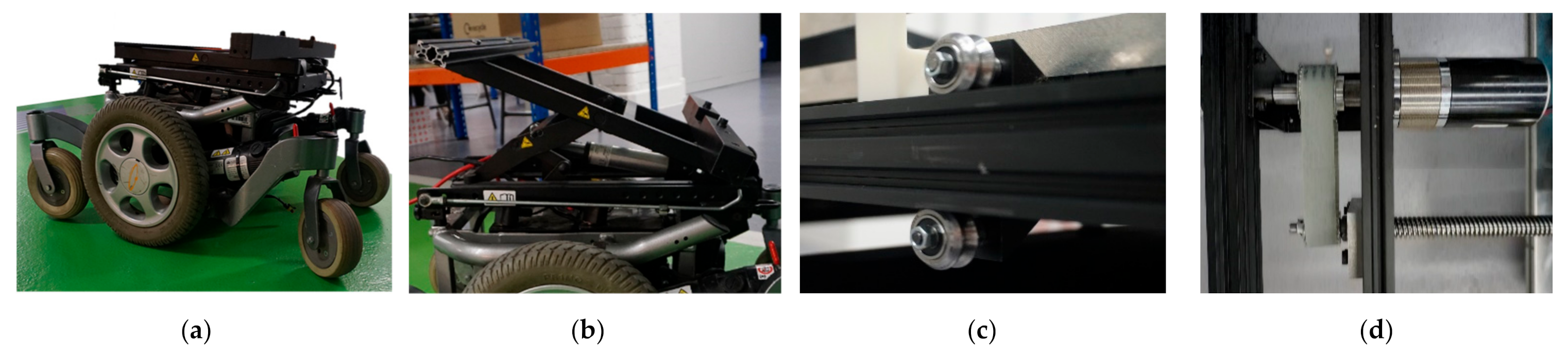
5.2.1. Differential-Drive Mobile Base

ResQbot 2.0 is designed to use a differential-drive mobile base module for mobility. This module provides fast and flexible manoeuvrability in flat terrain typically found in urban and indoor environments. The mobile base platform is a customised version of a commercially available powered wheelchair—Quickie Salsa-M—manufactured by Sunrise Medical [62]. This mobile base has a versatile design and is stable since it was designed to transport a disabled person both indoors and outdoors. The differential-drive wheels are located at the centre to enable a compact turning circle. In order to ensure its stability and safety while manoeuvring, this platform is equipped with an all-wheel independent suspension and anti-pitch technology suitable for use on rough or uneven terrain. Moreover, this platform was designed to carry loads up to 140 kg, which makes it suitable for the ResQbot 2.0 application: To carry an average-size casualty weighing approximately 80–100 kg [62]. Other important reasons for choosing this mobile platform are its mission range and its maximum operational speed. This mobile base can cover up to 32 km with a 60 Ah battery [62], and it has a maximum speed of 10 kph [62]. Figure 11a shows the differential-drive mobile base module.

5.2.2. Stretcher Bed Tilting Module

The bed’s tilting mechanism is the powered seat-tilt mechanism used on the Quickie Salsa-M. This tilting mechanism can be adjusted to an angle between 0 and 30 degrees [62]. The tilting mechanism is driven by a linear actuator connected to bar linkage systems. This mechanism enables ResQbot 2.0 to assume the optimal loading angle for safe casualty extraction. Figure 11b shows the bed’s tilting mechanism.

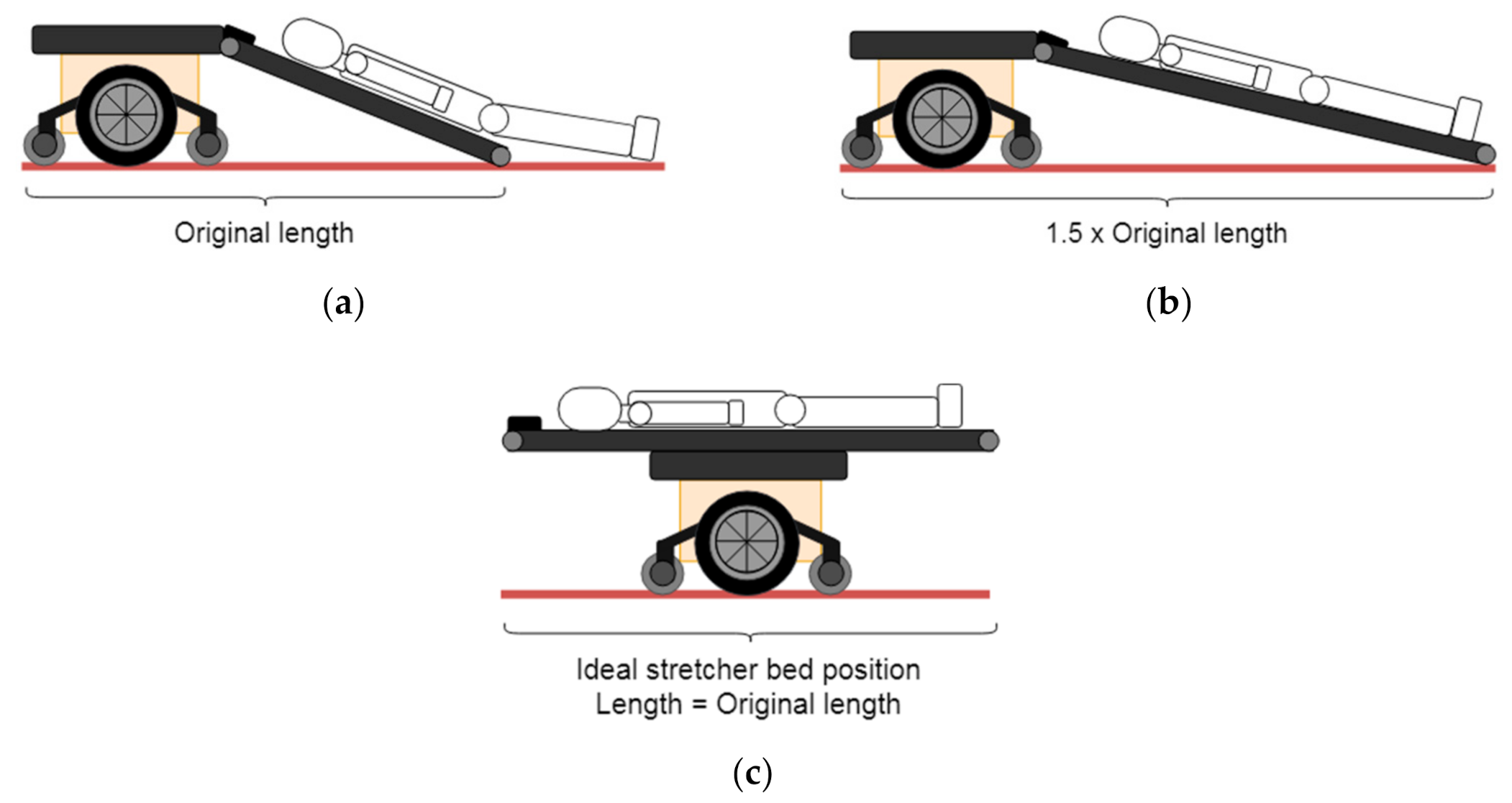
5.2.3. Stretcher Bed Sliding Module

The bed’s sliding module is designed to allow the stretcher bed to slide down (loading configuration) and slide up (compact transport configuration) during the casualty extraction process (see Figure 6). This module consists of two main mechanisms: The rail mechanism (see Figure 11c) and the lead-screw mechanism (see Figure 11d).
The sliding rail mechanism holds the stretcher bed on the fixed frame and allows it to slide along one axis. The mechanism bears the maximum load of the bed. Eight pairs of chrome steel metal dual V-wheels are used for the roller mechanism that holds the aluminium V-slot extrusion (i.e., the rail). This mechanism is recommended for accurate linear motion and has a high load capacity [63]. We installed four pairs of V-wheels on each side of the bed (eight pairs in total) to support a maximum load of 120 kg, including the casualty’s weight.
To drive the sliding module, the bed’s sliding-rail mechanism is connected to a lead-screw mechanism driven by a motor with a modular belt-pulley transmission system that allows the bed to slide up and down in order to load a casualty. During the design process, we considered several different mechanisms for this module: A ball screw, rack and pinion, lead screw, and winch were considered. Insights from the literature and expert opinions were obtained in order to evaluate the advantages and disadvantages of the different options, particularly with regards to cost-effectiveness, reliability and size, and the lead-screw mechanism was considered to be the most suitable. Even though it is not the most efficient in terms of friction, it allows for precise movement control, easy assembly, and is the most cost-effective solution, given budget constraints. Obviously, precise movement control is a critical parameter in the ResQbot 2.0 design specification since it is directly linked to safety.

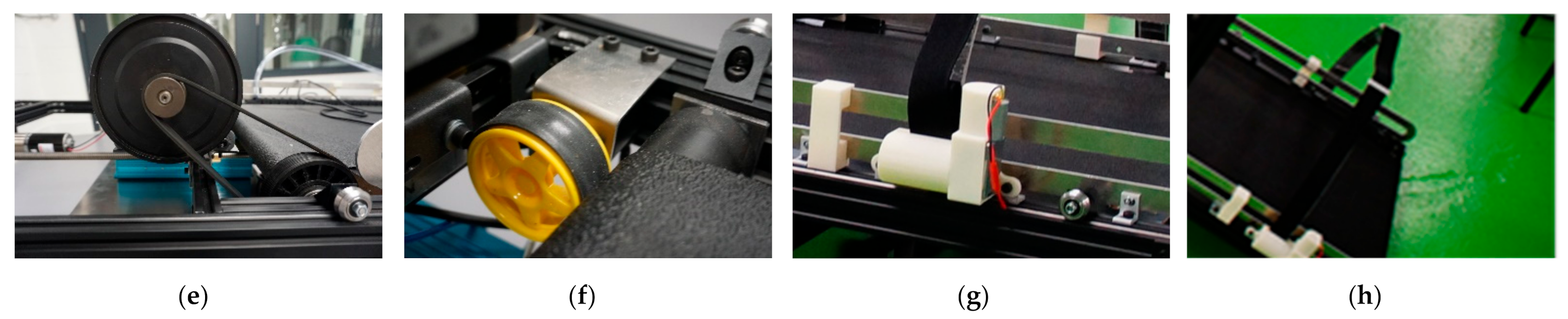
5.2.4. Stretcher Bed Conveyor Belt Mechanism

Similar to its predecessor (ResQbot 1.0), ResQbot 2.0 is equipped with an active stretcher bed module that actively pulls the casualty’s body up during the casualty extraction procedure. While the stretcher-bed module in ResQbot 1.0 is only capable of loading half of the casualty’s body, the stretcher bed module in ResQbot 2.0 is designed to load the entire body of an average-size human casualty.
This stretcher-bed module incorporates a conveyor belt capable of transporting a maximum payload of approximately 100 kg at its maximum power. The conveyor belt is powered by a 240 V DC motor controlled through a driver module powered by a 240 V AC onboard power inverter. A pulse-width modulation (PWM) control signal is used to control the motor’s speed. Figure 11e shows the electric motor and pulley-belt transmission system driving the conveyor belt.
In order to allow a closed-loop control for the conveyor belt’s speed, the conveyor belt module is equipped with an incremental rotary encoder connected to the conveyor’s pulley (see Figure 11f). This closed-loop control is essential in order to synchronise the conveyor belt’s speed and the speed of the mobile base during the casualty loading process, which uses the loco-manipulation method, as explained in Section 4.

5.2.5. Stretcher Strap Mechanism

For safe transportation, the casualty has to be safely placed onto the stretcher bed, and the stretcher strap modules secure the casualty during transportation. The ResQbot 1.0 stretcher strap design was effective, catering to many different body sizes as well as being safe. However, the ResQbot 2.0 two stretcher strap modules are attached to the stretcher bed module to accommodate a casualty’s entire body. One strap module secures and stabilises the casualty’s torso, and the other secures the legs. Each strap module is driven by a 24 V DC motor (see Figure 11g). These motors are controlled to fasten and unfasten the straps during the casualty-extraction procedure. The straps’ fastening force is controlled by regulating the motors’ power so that it is sufficient to secure the casualty without exerting too much pressure on the casualty’s body. Figure 11h shows the stretcher’s strap module.

5.2.6. Neck Securing Device Module

The neck securing device (NSD) features three main components/mechanisms: (1) A frame designed to be as compact as possible and encase all the safety mechanisms implemented on the NSD; (2) inflatable components that are the main protection against any cervical spine and head injuries during the loading procedure; and (3) a sliding rail mechanism that guides the NSD when it moves up or down along the belt.
The NSD frame was designed to cover the casualty’s head and neck up to the shoulders, as illustrated in Figure 7c. The frame’s design allows sufficient space between the casualty’s head, neck, and the frame in order to prevent any direct contact. The NSD slides along the bed to the ground and slides back up around the bed end. For that reason, the back of the device is curved to allow a smooth up and down motion (see Figure 12a).
The NSD inflatable components consist of three separate inflatable modules: One lifts and supports the back of the head, and two support the neck, as shown in Figure 12b. The inflatable modules are inflated by means of a pressurised air chamber that is controlled by a solenoid valve. In order to fully support the neck and head, the inflatables curve around the neck to stabilise the head and prevent unwanted movement. The neck support modules support the neck from each side, and during inflation, the modules slightly lift the neck and support it from the bottom. This allows the head to bend back slightly to facilitate unblocking the respiratory tracts. Figure 12c shows the inflatable components of the NSD module.
In order to guide the NSD up and down the stretcher bed, a pair of sliding guides were developed. They consist of two long rails attached to each side of the stretcher bed, a rod that slides up and down along the rails, and two pin joints connecting each side of the NSD frame to the sliding rod. Figure 12d shows the NSD sliding rail mechanism.

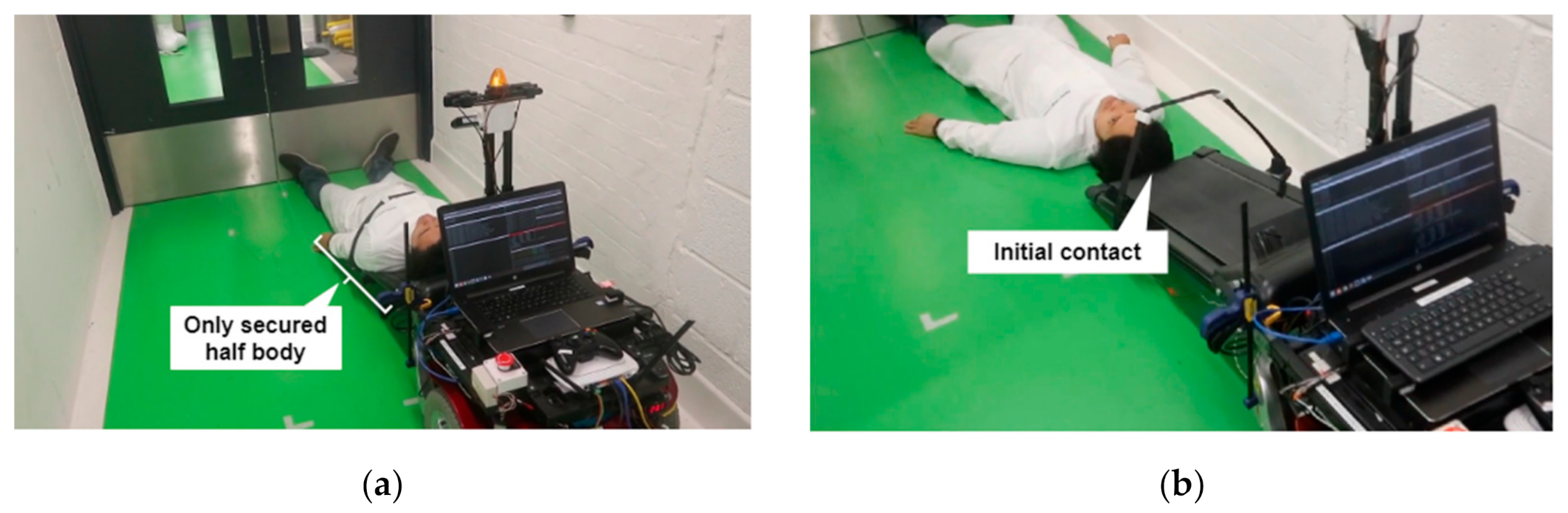
5.3. ResQbot 2.0 Casualty Extraction Simulation

In order to evaluate the ResQbot 2.0. design, we built a model using the Gazebo physics engine simulator to simulate the casualty extraction procedure (illustrated in Figure 5 and Figure 7). Figure 13 shows the sequential snapshots (a,b,c) of ResQbot 2.0 carrying out a simulated casualty extraction. The simulation demonstrates the proposed casualty extraction method introduced in Section 4. The snapshot images show that the ResQbot 2.0 design enables it to successfully carry out the complete casualty extraction procedure. Additionally, upon the publication, we will upload any additional experiment results and videos to the ResQbot web page, including the link to the open-source Gazebo simulation model of ResQbot 2.0 (https://www.imperial.ac.uk/robot-intelligence/robots/resqbot/ (accessed on 15 May 2021)) [64].

6. Conclusions and Future Work

In this work, we propose ResQbot 2.0, a novel design for a mobile rescue robot used for casualty extraction. It is a stretcher-type casualty extraction robot capable of safely performing casualty extraction using a loco-manipulation approach that is synchronised with a conveyor belt (a component of the ResQbot 2.0 stretcher bed module) and a mobile base to gently load a casualty from the ground onto the robot’s stretcher bed. We propose a new casualty extraction procedure using the novel features in ResQbot 2.0 in order to ensure a safe casualty extraction routine. We verified the proposed design and the casualty extraction procedure by conducting simulation experiments in the Gazebo physics engine simulator. Based on the simulation results, the ResQbot 2.0 design is a feasible option to successfully carry out a safe casualty extraction.
Ongoing work has been focused on the design and development of the ResQbot 2.0 platform. Unfortunately, due to the COVID-19 pandemic, currently we are only able to verify the design and development results using Gazebo, a physics engine simulator. In future work, we are eager to conduct an extensive number of physical experiments that we have developed to evaluate the ResQbot 2.0 performance during casualty extraction tasks in terms of safety, reliability, efficiency, and its limitations under various conditions. Human-robot teaming in several rescue scenarios could also be studied in depth in order to enable humans to successfully work together with ResQbot and increase the performance of the rescue missions. Moreover, since we have developed the open-sourced full model of the ResQbot 2.0 design for the Gazebo simulator, more advanced simulation experiments, such as a complete scenario of autonomous casualty extraction experiments, can be explored in the future works. The future generation of ResQbot evolution could support concurrent therapies, such as supplemental oxygen and other patient life supports, as well as the easy accessories attachment, such as air monitoring devices in CBRN incidents and cameras in other incidents.

Author Contributions

Conceptualisation, R.P.S., I.K., J.B., A.G., A.D., E.d.C., and P.K.; formal analysis, R.P.S., I.K., J.B., A.G., A.D., and E.d.C.; investigation, R.P.S., I.K., J.B., A.G., A.D., and E.d.C.; methodology, R.P.S. and P.K.; software, R.P.S.; supervision, P.K.; validation, R.P.S., N.R., I.K., J.B., A.G., A.D., E.d.C., S.R., and R.H.; visualisation, R.P.S. and J.B.; writing—original draft, R.P.S. and N.R.; writing—review and editing, N.R. and P.K. All authors have read and agreed to the published version of the manuscript.

Funding

Roni Permana Saputra received a fully financial support for his Ph.D. program through the Indonesia Endowment Fund for Education (LPDP).

Institutional Review Board Statement

Not applicable.

Informed Consent Statement

Not applicable.

Data Availability Statement

Not applicable.

Acknowledgments

The authors would like to thank you for the feedback received from the NHS London Ambulance Service team at the arranged meeting on Tuesday 4 June 2019 at the Dyson School of Design Engineering, Imperial College London.

Conflicts of Interest

The authors declare no conflict of interest.

Abbreviations

The following abbreviations are used in this manuscript:
SARSearch and Rescue
CBRNChemical, Biological, Radiological, and Nuclear
TAGSTactical Amphibious Ground Support System
REXRobotic Extraction
REVRobotic Evacuation
NSDNeck Securing Device
UAVUnmanned Aerial Vehicle
UGVUnmanned Ground Vehicle

References

  1. Dinh, M.M.; Bein, K.; Roncal, S.; Byrne, C.M.; Petchell, J.; Brennan, J. Redefining the Golden Hour for Severe Head Injury in an Urban Setting: The Effect of Prehospital Arrival Times on Patient Outcomes. Injury 2013, 44, 606–610. [Google Scholar] [CrossRef] [PubMed]
  2. Harmsen, A.M.K.; Giannakopoulos, G.F.; Moerbeek, P.R.; Jansma, E.P.; Bonjer, H.J.; Bloemers, F.W. The Influence of Prehospital Time on Trauma Patients Outcome: A Systematic Review. Injury 2015, 46, 602–609. [Google Scholar] [CrossRef] [PubMed]
  3. Lerner, E.B.; Moscati, R.M. The Golden Hour: Scientific Fact or Medical “Urban Legend”? Acad. Emerg. Med. 2001, 8, 758–760. [Google Scholar] [CrossRef] [PubMed]
  4. Williams, A.; Sebastian, B.; Ben-Tzvi, P. Review and Analysis of Search, Extraction, Evacuation, and Medical Field Treatment Robots. J. Intell. Robot. Syst. 2019, 96, 401–418. [Google Scholar] [CrossRef]
  5. Murphy, R.R.; Tadokoro, S.; Nardi, D.; Jacoff, A.; Fiorini, P.; Choset, H.; Erkmen, A.M. Search and Rescue Robotics. In Springer Handbook of Robotics; Siciliano, B., Khatib, O., Eds.; Springer: Berlin/Heidelberg, Germany, 2008; pp. 1151–1173. ISBN 978-3-540-30301-5. [Google Scholar]
  6. Yoo, A.C.; Gilbert, G.R.; Broderick, T.J. Military Robotic Combat Casualty Extraction and Care. In Surgical Robotics: Systems Applications and Visions; Rosen, J., Hannaford, B., Satava, R.M., Eds.; Springer: Boston, MA, USA, 2011; pp. 13–32. ISBN 978-1-4419-1126-1. [Google Scholar]
  7. Theobald, D. Mobile Extraction-Assist Robot. U.S. Patent 7719222B2, 18 May 2010. [Google Scholar]
  8. Hu, J.; Lim, Y.-J. Robotic First Responder System and Method. U.S. Patent 20140150806A1, 5 June 2014. [Google Scholar]
  9. Delmerico, J.; Mintchev, S.; Giusti, A.; Gromov, B.; Melo, K.; Horvat, T.; Cadena, C.; Hutter, M.; Ijspeert, A.; Floreano, D.; et al. The Current State and Future Outlook of Rescue Robotics. J. Field Robot. 2019, 36, 1171–1191. [Google Scholar] [CrossRef]
  10. West, C.; Arvin, F.; Cheah, W.; West, A.; Watson, S.; Giuliani, M.; Lennox, B. A Debris Clearance Robot for Extreme Environments. In Towards Autonomous Robotic Systems; Althoefer, K., Konstantinova, J., Zhang, K., Eds.; Springer International Publishing: Cham, Switzerland, 2019; pp. 148–159. [Google Scholar]
  11. Mandow, A.; Serón, J.; Pastor, F.; García-Cerezo, A. Experimental Validation of a Robotic Stretcher for Casualty Evacuation in a Man-Made Disaster Exercise. In Proceedings of the 2020 IEEE International Symposium on Safety, Security, and Rescue Robotics (SSRR), Virtual, 4–6 November 2020; pp. 241–245. [Google Scholar]
  12. Yeong, S.P.; King, M.; Dol, S.S. A Review on Marine Search and Rescue Operations Using Unmanned Aerial Vehicles. World Acad. Sci. Eng. Technol. Int. J. Mar. Environ. Sci. 2015, 9, 396–399. [Google Scholar]
  13. Mishra, B.; Garg, D.; Narang, P.; Mishra, V. Drone-Surveillance for Search and Rescue in Natural Disaster. Comput. Commun. 2020, 156, 1–10. [Google Scholar] [CrossRef]
  14. Quan, A.; Herrmann, C.; Soliman, H. Project Vulture: A Prototype for Using Drones in Search and Rescue Operations. In Proceedings of the 15th International Conference on Distributed Computing in Sensor Systems (DCOSS), Santorini, Greece, 29–31 May 2019; pp. 619–624. [Google Scholar] [CrossRef]
  15. Karaca, Y.; Cicek, M.; Tatli, O.; Sahin, A.; Pasli, S.; Beser, M.F.; Turedi, S. The Potential Use of Unmanned Aircraft Systems (Drones) in Mountain Search and Rescue Operations. Am. J. Emerg. Med. 2018, 36, 583–588. [Google Scholar] [CrossRef]
  16. McRae, J.N.; Gay, C.J.; Nielsen, B.M.; Hunt, A.P. Using an Unmanned Aircraft System (Drone) to Conduct a Complex High Altitude Search and Rescue Operation: A Case Study. Wilderness Environ. Med. 2019, 30, 287–290. [Google Scholar] [CrossRef] [Green Version]
  17. Hayley Drones for Search and Rescue. Available online: https://coptrz.com/drone-in-sar-operations/ (accessed on 13 May 2021).
  18. Dukowitz, Z. Drones in Search and Rescue: 5 Stories Show Casing Ways Search and Rescue Uses Drones to Save Lives. Available online: https://uavcoach.com/search-and-rescue-drones/ (accessed on 13 May 2021).
  19. Saputra, R.P.; Kormushev, P. Resqbot: A Mobile Rescue Robot with Immersive Teleperception for Casualty Extraction. In Proceedings of the Annual Conference Towards Autonomous Robotic Systems, Bristol, UK, 25–27 July 2018; Springer: Berlin/Heidelberg, Germany, 2018; pp. 209–220. [Google Scholar]
  20. Saputra, R.P.; Rakicevic, N.; Kormushev, P. Sim-to-Real Learning for Casualty Detection from Ground Projected Point Cloud Data. arXiv 2019, arXiv:1908.03057. [Google Scholar]
  21. Saputra, R.P.; Rakicevic, N.; Chappell, D.; Wang, K.; Kormushev, P. Hierarchical Decomposed-Objective Model Predictive Control for Autonomous Casualty Extraction. IEEE Access 2021, 1. [Google Scholar] [CrossRef]
  22. Saputra, R.P.; Kormushev, P. Casualty Detection from 3D Point Cloud Data for Autonomous Ground Mobile Rescue Robots. In Proceedings of the 2018 IEEE International Symposium on Safety, Security, and Rescue Robotics, SSRR 2018, Philadeplhia, PA, USA, 6–8 August 2018. [Google Scholar]
  23. Saputra, R.P.; Kormushev, P. ResQbot: A Mobile Rescue Robot for Casualty Extraction. In Proceedings of the Companion of the 2018 ACM/IEEE International Conference on Human-Robot Interaction, Chicago, IL, USA, 5–8 March 2018; pp. 239–240. [Google Scholar]
  24. Wikimedia Commons Spanish Army IRobot PackBot 510 IED Robot. Available online: https://commons.wikimedia.org/wiki/File:IRobot_PackBot_510_E.T..JPG (accessed on 4 June 2021).
  25. Gilbert, G.R.; Beebe, M.K. United States Department of Defense Research in Robotic Unmanned Systems for Combat Casualty Care; U.S. Department of Defense: Washington, DC, USA, 2010.
  26. Gilbert, G.; Turner, T.; Marchessault, R. Army Medical Robotics Research; United States Army Medical Research and Materiel Command: Fort Detrick, MD, USA, 2007. [Google Scholar]
  27. Quick, D. Battlefield Extraction-Assist Robot to Ferry Wounded to Safety. Available online: https://newatlas.com/battlefield-extraction-assist-robot/17059/1/9%0AROBOTICS%0ABattle (accessed on 13 May 2021).
  28. Ning, M.; Ma, Z.; Chen, H.; Cao, J.; Zhu, C.; Liu, Y.; Wang, Y. Design and Analysis for a Multifunctional Rescue Robot with Four-Bar Wheel-Legged Structure. Adv. Mech. Eng. 2018, 10, 1687814017747399. [Google Scholar] [CrossRef] [Green Version]
  29. Choi, B.; Lee, W.; Park, G.; Lee, Y.; Min, J.; Hong, S. Development and Control of a Military Rescue Robot for Casualty Extraction Task. J. Field Robot. 2019, 36, 656–676. [Google Scholar] [CrossRef]
  30. Williams, A.; Sebastian, B.; Ben-Tzvi, P. A Robotic Head Stabilization Device for Medical Transport. Robotics 2019, 8, 23. [Google Scholar] [CrossRef] [Green Version]
  31. Iwano, Y.; Osuka, K.; Amano, H. Evaluation of Rescue Support Stretcher System. In Proceedings of the 2012 IEEE RO-MAN: The 21st IEEE International Symposium on Robot and Human Interactive Communication, Paris, France, 9–13 September 2012; pp. 245–250. [Google Scholar]
  32. Yamauchi, B. PackBot: A Versatile Platform for Military Robotics. In Proceedings of the Unmanned Ground Vehicle Technology VI; SPIE: Bellingham, WA,USA, 2004; Volume 5422, pp. 228–237. [Google Scholar]
  33. Hstar Technology. Hstar Technology Research Programs. Available online: http://hstar.ishopworld.com/solutions/research_programs.html (accessed on 11 May 2021).
  34. Lee, W.; Lee, Y.; Park, G.; Hong, S.; Kang, Y. A Whole-Body Rescue Motion Control with Task-Priority Strategy for a Rescue Robot. Auton. Robot. 2017, 41, 243–258. [Google Scholar] [CrossRef]
  35. Choi, B.; Park, G.; Lee, Y. Practical Control of a Rescue Robot While Maneuvering on Uneven Terrain. J. Mech. Sci. Technol. 2018, 32, 2021–2028. [Google Scholar] [CrossRef]
  36. Iwano, Y.; Osuka, K.; Amano, H. Development of Stretcher Component Robots for Rescue Activity. In Proceedings of the IEEE Conference on Robotics, Automation and Mechatronics, Singapore, 1–3 December 2004; Volume 2, pp. 915–920. [Google Scholar]
  37. Iwano, Y.; Osuka, K.; Amano, H. Development of Rescue Support Stretcher System. In Proceedings of the 2010 IEEE Safety Security and Rescue Robotics, Bremem, Germany, 26–30 July 2010; pp. 1–6. [Google Scholar]
  38. Iwano, Y.; Osuka, K.; Amano, H. Development of Rescue Support Stretcher System with Stair-Climbing. In Proceedings of the 2011 IEEE International Symposium on Safety, Security, and Rescue Robotics, Kyoto, Japan, 1–5 November 2011; pp. 245–250. [Google Scholar]
  39. Miyazawa, K. Fire Robots Developed by the Tokyo Fire Department. Adv. Robot. 2002, 16, 553–556. [Google Scholar] [CrossRef]
  40. Sebastian, B.; Williams, A.; Ben-Tzvi, P. Control of a Head Stabilization System for Use in Robotic Disaster Response. In Proceedings of the ASME 2017 International Mechanical Engineering Congress and Exposition IMECE2017, Tampa, FL, USA, 3–9 November 2017. [Google Scholar]
  41. Sebastian, B. Traversability Estimation Techniques for Improved Navigation of Tracked Mobile Robots. Ph.D. Thesis, Virginia Polytechnic Institute and State University, Blacksburg, VA, USA, 2019. [Google Scholar]
  42. Williams, A.J. A Robotic Head Stabilization Device for Post-Trauma Transport. Master’s Thesis, Virginia Tech, Blacksburg, VA, USA, 2018. [Google Scholar]
  43. Engsberg, J.R.; Standeven, J.W.; Shurtleff, T.L.; Tricamo, J.M.; Landau, W.M. Spinal Cord and Brain Injury Protection: Testing Concept for a Protective Device. Spinal Cord 2009, 47, 634–639. [Google Scholar] [CrossRef]
  44. Payne, A.R.; Patel, S. Injury Mechanisms & Injury Criteria: Head Injury Mechanisms And Injury Criteria. Available online: http://www.eurailsafe.net/subsites/operas/HTML/Section3/Section3.3frm.htm (accessed on 15 March 2021).
  45. Herring, C.L. Rescue Carriers and Drags; FETI Drill Guide 14-09; Louisiana State University: Baton Rouge, LA, USA, 2014. [Google Scholar]
  46. Fire Engineering Training Minutes: Webbing and Victim Drag Techniques. Available online: https://www.fireengineering.com/training/training-minutes-webbing-and-victim-drag-techniques/ (accessed on 1 April 2021).
  47. Finazzo, S. Carrying & Dragging Techniques—Lets Get Carried Away. Available online: https://www.offgridweb.com/preparation/carrying-dragging-techniques-lets-get-carried-away/ (accessed on 1 April 2021).
  48. Hann, A. A Photographic Guide to Prehospital Spinal Care; Emergency Technologies: Raleigh, NC, USA, 2004. [Google Scholar]
  49. Coen, S.D. Spinal Cord Injury: Preventing Secondary Injury. AACN Clin. Issues Crit. Care Nurs. 1992, 3, 44–54. [Google Scholar] [CrossRef]
  50. Abram, S.; Bulstrode, C. Routine Spinal Immobilization in Trauma Patients: What Are the Advantages and Disadvantages? Surgeon 2010, 8, 218–222. [Google Scholar] [CrossRef]
  51. Vaillancourt, C.; Stiell, I.G.; Beaudoin, T.; Maloney, J.; Anton, A.R.; Bradford, P.; Cain, E.; Travers, A.; Stempien, M.; Lees, M. The Out-of-Hospital Validation of the Canadian C-Spine Rule by Paramedics. Ann. Emerg. Med. 2009, 54, 663–671. [Google Scholar] [CrossRef]
  52. Connell, R.A.; Graham, C.A.; Munro, P.T. Is Spinal Immobilisation Necessary for All Patients Sustaining Isolated Penetrating Trauma? Injury 2003, 34, 912–914. [Google Scholar] [CrossRef]
  53. Holla, M.; Huisman, J.M.R.; Verdonschot, N.; Goosen, J.; Hosman, A.J.F.; Hannink, G. The Ability of External Immobilizers to Restrict Movement of the Cervical Spine: A Systematic Review. Eur. Spine J. 2016, 25, 2023–2036. [Google Scholar] [CrossRef] [PubMed] [Green Version]
  54. Stuke, L.E.; Pons, P.T.; Guy, J.S.; Chapleau, W.P.; Butler, F.K.; McSwain, N.E. Prehospital Spine Immobilization for Penetrating Trauma—Review and Recommendations from the Prehospital Trauma Life Support Executive Committee. J. Trauma Acute Care Surg. 2011, 71, 763–770. [Google Scholar] [CrossRef] [PubMed] [Green Version]
  55. Eastridge, B.J.; Mabry, R.L.; Seguin, P.; Cantrell, J.; Tops, T.; Uribe, P.; Mallett, O.; Zubko, T.; Oetjen-Gerdes, L.; Rasmussen, T.E.; et al. Death on the Battlefield (2001–2011): Implications for the Future of Combat Casualty Care. J. Trauma Acute Care Surg. 2012, 73, S431–S437. [Google Scholar] [CrossRef] [PubMed]
  56. Kwan, I.; Bunn, F.; Roberts, I.G. Spinal Immobilisation for Trauma Patients. Cochrane Database Syst. Rev. 2001. [Google Scholar] [CrossRef] [PubMed]
  57. Peck, G.E.; Shipway, D.J.H.; Tsang, K.; Fertleman, M. Cervical Spine Immobilisation in the Elderly: A Literature Review. Br. J. Neurosurg. 2018, 32, 286–290. [Google Scholar] [CrossRef]
  58. Head Injury Criteria Tolerance Levels. Available online: http://www.eurailsafe.net/subsites/operas/HTML/Section3/Page3.3.1.4.htm (accessed on 15 March 2021).
  59. Carlström, V. This New Airbag Collar Is a Safer Alternative to the Traditional Bike Helmet—And It’ll Soon Be Available across the Globe. Available online: https://www.businessinsider.com/a-new-inflatable-collar-is-safer-than-the-traditional-bike-helmet-2018-8?r=US&IR=T (accessed on 19 March 2021).
  60. Nextcrave Hovding Invisible Bike Helmet. Available online: http://www.nextcrave.com/content/999-hovding-invisible-bike-helmet (accessed on 14 May 2021).
  61. Sareen, H.; Umapathi, U.; Shin, P.; Kakehi, Y.; Ou, J.; Ishii, H.; Maes, P. Printflatables: Printing Human-Scale, Functional and Dynamic Inflatable Objects. In Proceedings of the 2017 CHI Conference on Human Factors in Computing Systems, Denver, CO, USA, 6–11 May 2017; Association for Computing Machinery: New York, NY, USA, 2017; pp. 3669–3680. [Google Scholar]
  62. Sunrise Medical Salsa M2 Powered Wheelchair. Available online: https://www.sunrisemedical.co.uk/powered-wheelchairs/quickie/power-wheelchairs/quickie-salsa-m2 (accessed on 23 March 2021).
  63. Ooznest Metal Dual V Wheel. Available online: https://ooznest.co.uk/product/metal-dual-v-wheel (accessed on 23 March 2021).
  64. ResQbot. Available online: https://www.imperial.ac.uk/robot-intelligence/robots/resqbot/ (accessed on 13 May 2021).
Figure 1. Timeline of the major contributions to the field of casualty extraction (photos on the diagram are adapted from [23,24,25,26,27,28,29,30,31]).
Applsci 11 05414 g001
Figure 2. Casualty extraction procedures using two different types of casualty extraction robots. (a) Humanoid-type robot construction. The casualty extraction procedure has been presented in [29]. We found that there are at least three safety concerns in the typical humanoid-type robot construction procedure, the impact during the casualty scooping process could possibly bend the casualty’s body sideways, the lifting process could make the casualty’s body bend forward, and provide minimal support for the casualty’s head and neck during the transportation phase. (b) Stretcher-type robot construction. The presented casualty extraction procedure introduced as the loco-manipulation approach has been presented in [23].
Applsci 11 05414 g002
Figure 3. Two critical concerns of the ResQbot 1.0 design: (a) ResQbot 1.0 can only load and secure half of the casualty’s body (i.e., upper body). (b) The initial contact between the robot and the casualty’s head during the casualty loading process remains a critical safety concern (the potential cause of head or neck injury).
Applsci 11 05414 g003
Figure 4. Illustration showing the ResQbot 1.0 stretcher-bed conveyor in comparison to the longer stretcher-bed conveyor designs that enable safe loading of the casualty’s entire body onto the stretcher bed. (a) ResQbot 1.0 original size. (b) ResQbot 1.0 with an expanded stretcher bed. (c) The ideal position of the stretcher bed on the differential-drive mobile base (i.e., proposed design).
Applsci 11 05414 g004
Figure 5. Illustration of proposed tilting mechanism and sliding mechanism adapted in the ResQbot 2.0 proposed design. These mechanisms were adapted in order to accommodate the upgraded size of the stretcher bed—capable of loading the entire body of an average-size casualty—while maintaining the overall compact design of the robot.
Applsci 11 05414 g005
Figure 6. Illustration of the proposed casualty extraction procedure using ResQbot 2.0 comprising of seven main sequential phases: (1) Aligning the robot’s pose with respect to the casualty’s orientation. (2) Approaching the casualty in the desired target position in readiness to load the casualty. (3) Changing to the loading configuration by tilting and sliding the robot’s stretcher bed to the desired configuration. (4) Synchronising the robot’s mobile base and the conveyor belt movements enables the robot to gently load the casualty onto the stretcher bed. (5) Once the casualty is correctly positioned on the robot, the stretcher’s strap mechanism securely fastens, stabilises, and safely immobilises the casualty on the stretcher bed. (6) Changing back to the compact configuration by sliding up and tilting down the robot’s stretcher bed. (7) The robot is ready to transport the casualty to the medical area for further treatment.
Applsci 11 05414 g006
Figure 7. Several concepts of protecting the head from possible injuries. (a) The head support system proposed in [30,40] to immobilise the head during casualty extraction. (b) Hovding inflatable cycling helmet, as presented in [59,60], that protects the cyclist’s head during a crash. (c) Proposed neck securing device (NSD), using the inflatable mechanism proposed for the ResQbot 2.0 design.
Applsci 11 05414 g007
Figure 8. Illustration of the updated procedure to load casualties by means of the NSD system. This procedure is an extension of Step 4 in Figure 6. (4a) Once the robot achieves the desired loading configuration, the NSD module is sliding down, approaching the casualty. (4b) The NSD frame is placed in the desired position so that the casualty’s head and neck are in the NSD frame centre. (4c) The inflatable system of the NSD then slowly inflates and stabilises the casualty’s head and neck. (4d) Initiating the casualty loading process by synchronising the movement of the base and the motion of the belt conveyor.
Applsci 11 05414 g008
Figure 9. The ResQbot 2.0 design comprises seven main novel components: A differential-drive mobile base; a stretcher bed tilting mechanism; a stretcher bed sliding mechanism; a motorised stretcher bed conveyor module; a pair of motorised stretcher strap modules; and a neck securing device module.
Applsci 11 05414 g009
Figure 10. The fully assembled ResQbot 2.0. (a) The compact configuration is used for general navigation and casualty transportation. (b) ResQbot 2.0 in the loading configuration, allowing the robot to adjust its configuration to the optimal loading angle to perform the casualty extraction procedure safely.
Applsci 11 05414 g010
Figure 11. ResQbot 2.0 main modules. (a) Differential-drive mobile base module. (b) Stretcher bed tilting module. (c) The bed’s sliding-rail mechanism. (d) The motor drive and the lead-screw mechanism that enable the stretcher bed to slide. (e) The motor drive and transmission system of the conveyor module. (f) The rotary encoder of the conveyor module, which allows feedback control to synchronise the conveyor and mobile base speed during the casualty loading process. (g) DC motor to drive the strap fastening and securing mechanism. (h) The stretcher strap module attached to the stretcher bed.
Applsci 11 05414 g011aApplsci 11 05414 g011b
Figure 12. Design of the NSD module. The NSD module features three main components: An NSD frame, inflatable components, and a sliding guide mechanism. (a) The design has a curved shape to enable smooth loading up and down during the operation. (b) Design of the NSD inflatable components that support the casualty’s head and neck during the extraction procedure. (c) The NSD module. (d) The NSD sliding rail mechanism that allows it to slide up and down along the stretcher bed module.
Applsci 11 05414 g012aApplsci 11 05414 g012b
Figure 13. Sequential snapshots (ac) of ResQbot 2.0 carrying out a simulated casualty extraction, as proposed in Section 4.
Applsci 11 05414 g013aApplsci 11 05414 g013b
Publisher’s Note: MDPI stays neutral with regard to jurisdictional claims in published maps and institutional affiliations.

