Article

Task-Based Design Approach: Development of a Planar Cable-Driven Parallel Robot for Upper Limb Rehabilitation

1
Department of Mechanical Engineering and Complex Systems (GMSC), Pprime Institute French National Centre for Scientific Research (CNRS), National Higher School of Mechanics and Aeroengineering (ENSMA), University of Poitiers, UPR 3346 Poitiers, France
2
Mechanical Laboratory of Sousse (LMS), National Engineering School of Sousse, University of Sousse, Sousse 4000, Tunisia
3
Department of Mechanical Engineering, American University of Sharjah, Sharjah P.O. Box 26666, United Arab Emirates
*
Authors to whom correspondence should be addressed.
Appl. Sci. 2021, 11(12), 5635; https://doi.org/10.3390/app11125635
Submission received: 24 May 2021 / Revised: 11 June 2021 / Accepted: 14 June 2021 / Published: 18 June 2021
(This article belongs to the Special Issue Innovative Robot Designs and Approaches)

Abstract

:
This paper deals with the optimal design of a planar cable-driven parallel robot (CDPR), with three degrees of freedom, intended for assisting the patient’s affected upper limb along a prescribed movement. A Qualisys motion capture system was used to record the prescribed task performed by a healthy subject. For each pose taken by the center of mass of the end-effector, the cable tensions, the elastic stiffness and the dexterity were optimized while satisfying a set of constraints. First, a multiobjective formulation of the optimization problem was adopted. Since selecting a single solution among the multiple ones given by the Pareto front presents an issue, a mono-objective formulation was chosen, where the objective function was defined as a weighted sum of the chosen criteria. The appropriate values of the weighted coefficients were studied with the aim of identifying their influence on the optimization process and, thus, a judicious choice was made. A prototype of the optimal design of the CDPR was developed and validated experimentally on the prescribed workspace using the position control approach for the motors. The tests showed promising reliability of the proposed design for the task.

1. Introduction

Functional rehabilitation aims to recover as much as possible of the patient’s locomotion independence. It requires the assistance of a therapist to perform repetitive exercises for an injured member [1]. Task-oriented protocols, where the patient is assisted to perform a specific prescribed movement, such as kicking a ball or standing up and walking, show promising outcomes compared to the conventional training based on passively moving the impaired joints in the limits of their range of motion [2].
Rehabilitation sessions can last up to several weeks [3]. In addition, to guarantee a better quality of the followed protocol, one-to-one assistance is needed [4]. However, the limited number of available therapists influences the high-intensity and the repetition of the assistance. Given these issues, researchers have developed robotic devices to assist practitioners’ tasks [5,6,7,8,9]. They also provide the opportunity to assess the patient’s recovery progress and monitor protocol efficiency; for instance, by using ARMin [10], the ARM Guide [11], and the MIME [12].
The robotic devices used for clinical practice allow mainly the rehabilitation of the knee, the shoulder and the elbow [13]. Cable-driven parallel robots (CDPRs) [14] can be used to extend the coverage of existing robotic platforms since they allow rehabilitation of other joints [13]. They have also a larger translational workspace, less dynamic inertia and higher flexibility compared to serial manipulators [13]. Thanks to their simple reconfiguration and light weight, they have no setup constraints and can be used at the patients’ personal spaces to reduce the need to move to rehabilitation centers.
Various studies have been carried out dealing with the design [15], control [16,17,18] and the structural optimization of CDPRs. In [19], Lorenzo et al. studied the optimal position of the cable exit points allowing minimization of CDPR size for fully constrained and suspended configurations. In this work, the location of the cable exit points was supposed to be fixed, which was an unrealistic assumption. In [20], Hussein et al. optimized the CDPR geometry by minimizing the maximum cable tensions. This criterion could not guarantee minimum cable tensions since only the maximum value was optimized. Abbas et al. [21] studied the optimal design of a suspended CDPR using first the workspace area, then the global condition index, which describes the robot dexterity, as two separated objective functions and, thus, only one criterion in each optimization was used. Yangmin et al. [22] studied first, the optimal design of a CDPR taking into consideration the dexterity then the elastic stiffness as criteria, then a multiobjective optimization approach was used mixing the two characteristics. The selection of each criterion weight was chosen in a way that either the system was preferred to be more dexterous or stiffer. The authors chose to give the same importance to the two criteria. Such a choice can be improved by studying the influence of the variation of each coefficient on the objective function and on the criteria.
The gaps presented above are taken into consideration in this paper. The goal is to design a planar CDPR for upper limb rehabilitation. The prescribed exercise consists of tracing the number eight shape with the hand. This form was used among others since it involves shoulder and elbow motions [23]. The rehabilitation of the wrist joint was also considered since the hand orientation was not fixed. The cable tensions, the elastic stiffness and the dexterity were selected as the problem criteria. The choice of each criterion weight was justified, and the design parameters were set in a way to obtain a realistic design. This design problem can be formulated as a constrained optimization problem. Thus, this paper aims to design an optimal planar CDPR, based on the above-mentioned criteria, able to mobilize the patient’s affected upper limb along the prescribed task. The design optimization problem was formulated after considering the disadvantages of some proposed approaches introduced above. Once the optimal structure was selected, an experimental prototype was developed allowing a check of solution feasibility and reliability.
The paper is organized as follows: Section 2 details the experimental protocol followed to record the prescribed task. The planar CDPR model is presented as well as the criteria and the constraints adopted to seek the optimal design. In Section 3, the optimization results, using a multiobjective formulation then an adapted mono-objective formulation, are discussed and the experimental validation using a developed prototype is shown. The last section concludes the paper.

2. Materials and Methods

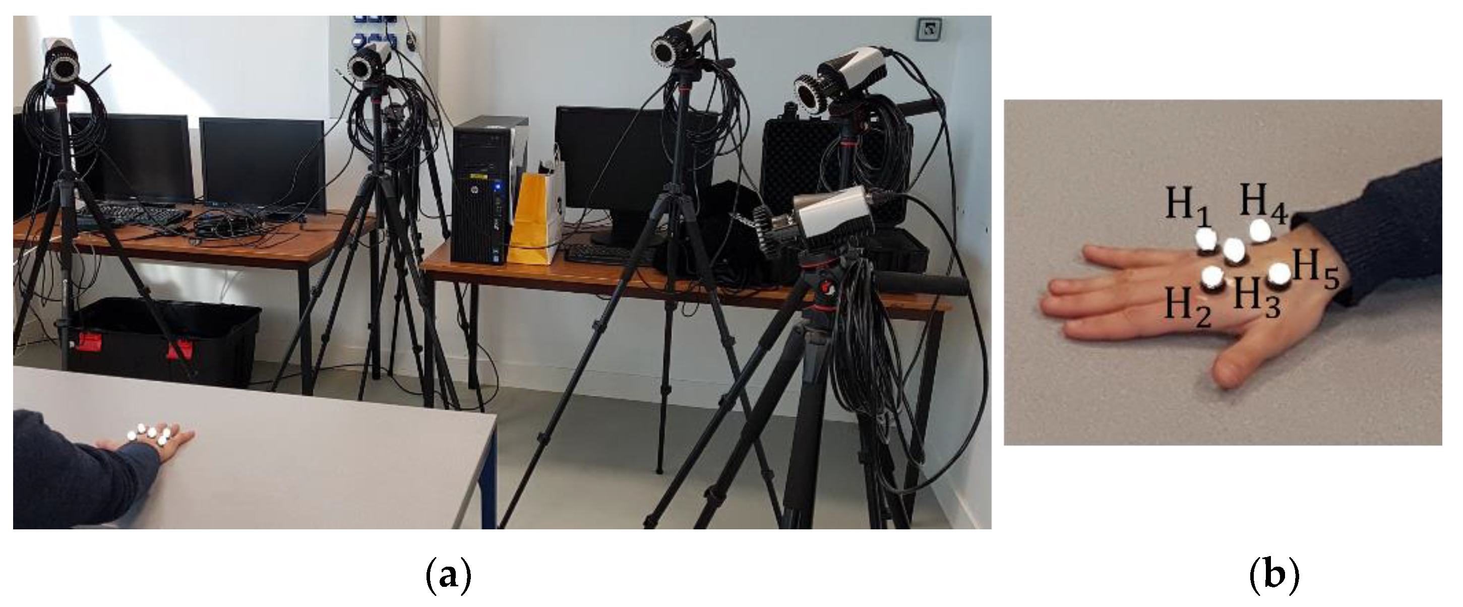
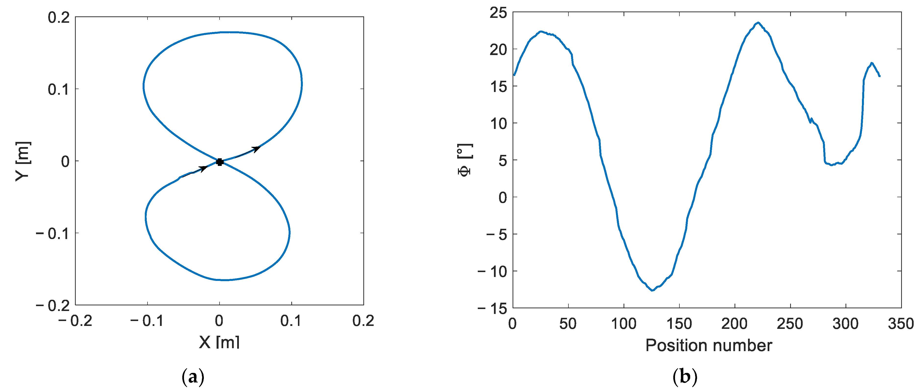
2.1. Prescribed Exercise Analysis

Rehabilitation aims to recover the functional abilities of the affected member by performing intensive and repetitive training [1]. The chosen exercise for this study was commonly performed for upper limb rehabilitation. It consisted of tracing with the hand an “8” curve. This exercise allows the rehabilitation of the three upper limb joints.
A healthy subject was asked to perform the prescribed drill in order to obtain a normal trajectory to use as a reference. This exercise involved five joints’ movements, namely the three rotations of the shoulder and the flexion/extension motion of the elbow and the wrist. The participant’s gestures were recorded using a Qualisys motion capture system with five infra-red cameras and five reflective markers attached to his hand as illustrated in Figure 1. Figure 2 illustrates the steps followed for the data acquisition.
The hand trajectory was defined by tracking the successive positions taken by the marker H3 during the prescribed exercise. Hand orientation was delimited by computing the rotation angle between a local frame ( H 3 ,   x ,   y ) attached to the participant’s hand and a global frame ( O ,   X ,   Y ) attached to the table as illustrated in Figure 3. Since the patient’s hand was attached to the robot end-effector, the recorded data, given in Figure 4, were used to define the robot’s prescribed workspace.

2.2. Optimal Synthesis Problem and Its Formulation

A planar cable-driven parallel robot with three degrees of freedom (DOFs) is considered in this paper. Since at least one more cable than the DOFs was needed to fully constrain the robot, four cables were used [24]. Their mass and elasticity were neglected. They were modeled as straight lines. The design process consisted of finding the optimal position of each actuator and the end-effector size satisfying a set of criteria and constraints. The motors’ positions were defined using the parameters a i and b i , which represent the coordinates of the center of the pulley P i , fixed on the i t h actuator. The mobile platform was considered as a square of side c (see Figure 5). The design vector is given by Equation (1). The global and the local frames ( X , Y ) and ( x , y ) , respectively, matched those represented in Figure 2, used for the motion capture analysis.
I = [ a 1 , b 1 ,   a 2 , b 2 ,   a 3 , b 3 ,   a 4 , b 4 ,   c ] ,
n i denotes the unit vector along the i t h cable. It is defined as follows, where ψ i and θ i are expressed as given in Equation (2). L i is the length of the i t h cable and R p is the pulleys’ radius. R p is considered to be fixed, since the cable radius and the coiling effects are neglected.
n 1 = [ sin   ( ψ 1 + θ 1 )   cos   ( ψ 1 + θ 1 ) ] , n 2 = [ sin   ( ψ 2 θ 2 )   cos   ( ψ 2 θ 2 ) ] , n 3 = [ sin   ( ψ 3 + θ 3 )   cos   ( ψ 3 + θ 3 ) ] ,   n 4 = [ sin   ( ψ 4 θ 4 )   cos   ( ψ 4 θ 4 ) ] ,
ψ i = tan 1 ( | P i x B i x | | P i y B i y | ) ,
θ i = tan 1 ( R p L i ) ,
The end-effector dynamic model was obtained using Newton-Euler formulation with the assumption of neglecting the cables mass and the dynamics of the pulleys. Its expression is given by Equation (5).
[ F M ] = M χ ¨ + C χ ˙ = J T T + f g + F e x t / E E ,
where M = [ m p I 3 × 3 0 3 3 0 3 × 3 R Φ   I p   R Φ T ] and C = [ 0 3 × 1 ω × R Φ I p   R Φ T ω ] are the mass and the Coriolis matrices, respectively. m p and ω are the mass and the angular velocity of the end-effector, R Φ is the rotation matrix, I p denotes the inertial matrix of the mobile platform written in its center of mass, χ = [ x   y   Φ ] T is the pose vector of the end-effector, J T is the transpose of the Jacobian matrix given in Equation (6), and T ,   f g , and F e x t / E E   are the cable tensions vector, the gravity force and the external forces applied on the end-effector, respectively.
J T = [ n i Z · ( R Φ · B i ) × n i   ] T ,     i = 1 .. 4 ,  
B i is the vector containing the anchor points coordinates ( B i ) in the local frame.
Thus, the expression of the cable tensions vector T can be deduced using Equation (5) as follows:
T = T p + T h = ( J T ) + ( M χ ¨ + C χ ˙ f g F e x t / O L   ) + λ   Null ( J T )
where T p and T h are the particular and the homogenous solutions, ( J T ) + is the Moore-Penrose pseudoinverse and λ   is an arbitrary scalar. The cable tensions must be bounded between a minimum positive and a maximum value in order to avoid slack and over-tensioned cables. This condition forms the first problem constraint, which is formulated as follows:
0 < T m i n T i ( j ) T m a x ,     i = 1 .. 4 ,     j = 1 .. n
where n is the number of points composing each trajectory, T i ( j ) is the tension of the i t h cable at the j t h position.
The second constraint concerns the collisions between the cables and the end-effector. to prevent this issue, the angle α i between the mobile platform and the i t h cable is computed for each position of the prescribed trajectories. α i must remain higher than a limit angle α l i m . The formulation of the collision constraint is given as follows:
α i = cos 1 ( n i   . m i m i ) > α l i m ,               i = 1 .. 4 ,
where m 1 = m 4 = B 1 B 4 , m 2 = m 3 = B 2 B 3 , and n i is the unit vector along the i t h cable as illustrated in Figure 5.
The last constraint concerns the location of the points P i . They must be located on the edges of the square forming the robot fixed frame. This constraint facilitates the robot reconfiguration when any other trajectory, included in the robot workspace, is selected.
The 4 × 3 Jacobian matrix J of the considered robot includes components of different physical units since the latter has mixed DOFs. To have a meaningful value of the condition number, the Jacobian matrix must be normalized allowing assessment of the closeness of a pose to a singularity. In order to settle the dimensional inhomogeneity, several methods have been suggested based on dividing the rotational elements of the Jacobian matrix J by a conventional length L . Lee et al. defined L in [25] as a nominal length represented by the distance between the origins of the global and the local frames. Angeles introduced in [26] the notion of natural length, which is the value of L that minimizes the condition number. This length is approximated to the radius of the end-effector [27]. The latter method was adopted in this paper. The homogenous Jacobian matrix, J h , of size 4 × 3, is calculated as given by Equation (10), where c is the side length of the mobile platform.
J h = J · d i a g ( 1 ,   1 ,   2 c 2 ) ,
Three criteria are considered for the optimization problem formulation, namely minimizing the tension in each cable and maximizing both the elastic stiffness and the dexterity of the end-effector. The first, the second, and the third criteria are characterized using the parameters C 1 , C 2 , and C 3 , respectively, as follows:
C 1 = 1 4 i = 1 4 j = 1 n T i ( j ) n   . max j = 1 .. n T i ( j ) ,
C 2 = 1 1 n j = 1 n λ m i n   ( j ) λ m a x   ( j ) ,
C 3 = 1 1 n j = 1 n σ m i n   ( j ) σ m a x   ( j ) ,
where λ and σ are the eigenvalue of the cable stiffness matrix and the singular value of the normalized Jacobian matrix J h . The maximum value of the ratios λ m i n λ m a x and σ m i n σ m a x is 1, thus, maximizing the elastic stiffness and the dexterity leads to minimizing the parameters C 2 and C 3 .

3. Results and Discussions

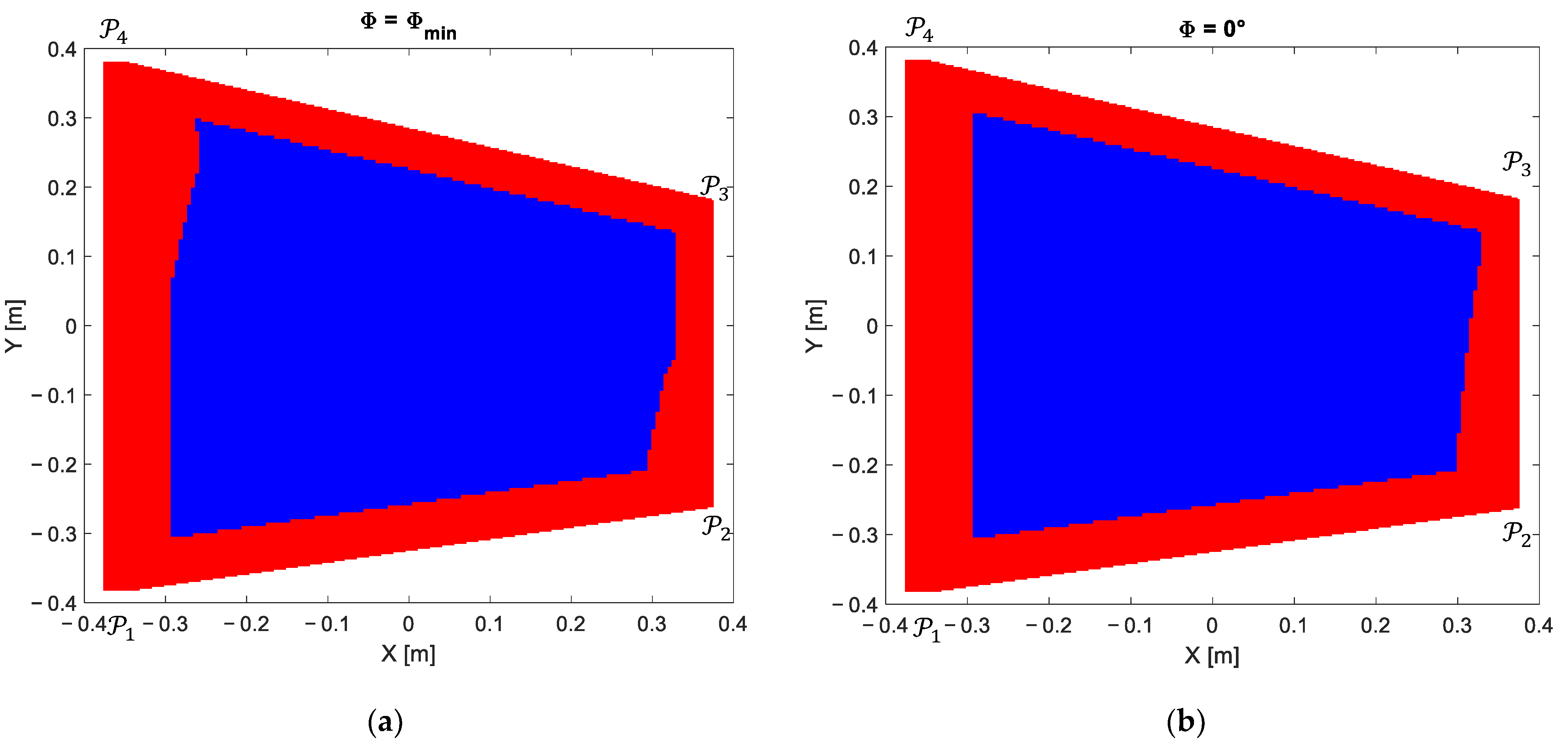
3.1. Multiobjective Formulation

The multiobjective formulation is given in Equation (14). A penalty formulation was adopted to handle the problem constraints.
{ min ( C 1 ( I ) + 1 + 2 + 3 ) , min ( C 2 ( I ) + 1 + 2 + 3 ) , min ( C 3 ( I ) + 1 + 2 + 3 ) ,
1 = { 0 if 0 < T m i n T i ( j ) T m a x ψ otherwise ,
2 = { 0 if α i > α l i m ψ otherwise ,
3 = { 0 if P i   ϵ   fixed   frame ψ otherwise ,
where i ,   i = 1 , 2 , 3 are the penalty functions and ψ is a large scalar.
Multiple solutions coexist forming the Pareto front displayed in Figure 6. Without adding supplementary information about the desired result, all the nondominated points form a potential optimal solution.
In order to facilitate its interpretation, two dimensions representations of the Pareto front are given. Figure 7 shows the cable tension vs the elastic stiffness criteria, the cable tension vs dexterity criteria, the dexterity vs the elastic stiffness criteria and the histogram of each criterion. The three criteria are normalized, and their values vary from 0 to 1.
The nondominated solutions for each two criteria present the preferable solutions if only the two corresponding objectives are considered. For the overall problem, the most desirable results are those which lay within the nondominated solutions of all the pairs illustrated in Figure 7. For the Pareto front presented above, the selection of the optimal solution was complicated since each solution minimized no more than two criteria and maximized those remaining. Additional subjective preference information was, therefore, needed to facilitate the decision-making.

3.2. Mono-Objective Formulation

Another method can be used for the resolution of a multiobjective optimization problem. This technique, called the scalarization method [28], consists of attributing a weight to each criterion that corresponds to the priority given to this objective in the optimization process. This method allows a single solution. Based on this technique, the modified optimization aims to find the optimal design vector I which minimizes the new objective function , defined as a weighted sum of the three subfunctions introduced above. The optimization problem is then formulated as follows:
min ( ( I ) ) , Subject   to 0 < T m i n T i ( j ) T m a x ,     i = 1 .. 4 ,     j = 1 .. n α i > α l i m ,               i = 1 .. 4 P i   ϵ   fixed   frame ,   i = 1 .. 4
The problem constraints are handled using a penalty approach. is then expressed as follows:
( I ) = β 1 C 1 ( I ) + β 2 C 2 ( I ) + β 3 C 3 ( I ) + 1 + 2 + 3 ,
where i ,   i = 1 , 2 , 3 are the penalty functions given by the Equations (15)–(17) and β 1 , β 2 and β 3 define the weight of each criterion. These coefficients must verify Equation (20).
i = 1 3 β i = 1 ,
Three strategies have been used in the literature to compute the values of the coefficients β i [29], namely, the equal weights method [30], the rank order centroid weights method [31] and the rank-sum weights method [31].
The equal weights method was used in our previous work [32]. In this paper, a deeper study of the appropriate values of these weighting coefficients is conducted in order to identify the impact of each coefficient on the quality of the final solution and the optimization process. A mapping of the global objective function and those corresponding to the three criteria is computed for all the possible coefficient values inside the interval (0,1) with respect to Equation (20), using the Particle Swarm Optimization algorithm (PSO) [33]. The computed variations are illustrated in Figure 8.
Referring to Figure 8d, the objective function decreases with β 1 . This means that the cable tension criterion C 1 has the greatest impact on the objective function compared to the other coefficients β 2 and β 3 . Thus, having a structure with a minimum cable tension distribution is easier than generating good dexterity and elastic stiffness.
As illustrated in Figure 8c, the dexterity criterion C 3 is nearly equal to 0.3 ( C 3   [ 0.3 ,   0.33 ] for β 3 = 0 and C 3 = 0.28 for β 3 = 1 ) . Thus, according to Equation (13), the robot dexterity remains between 0.67 and 0.72. In other words, it takes good values even when β 1 and β 2 are large ( β 3 is close to zero). This is contrary to the elastic stiffness criterion C 2 ,whose minimum value is equal to 0.58 for β 2 = 1 , which corresponds to an elastic stiffness equal to 0.42 (according to Equation (12)).
Based on this mapping study, since the dexterity has acceptable values for any chosen β 3 , the lowest coefficient is given to the criterion C 3 . The remaining weight is divided equally between the two other criteria. Thus, β 3 = 0.1 ,     β 1 = β 2 = 0.45 .
Several methods exist in the literature allowing the resolution of optimization problems [34,35]. Particle Swarm Optimization (PSO) was used in this paper to select the optimal design vector. The different parameters used for the problem resolution are listed in Table 1. The lower and the upper boundaries of each design parameter are listed in Table 2.
The obtained solution, as well as the corresponding values of the objective function and the three criteria, are given in Table 3.
The maximum cable tension, the elastic stiffness and the dexterity of the optimal robot structure computed along the task workspace are illustrated in Figure 9. Figure 10 displays the free collision static workspace of the optimal structure for different values of Φ .

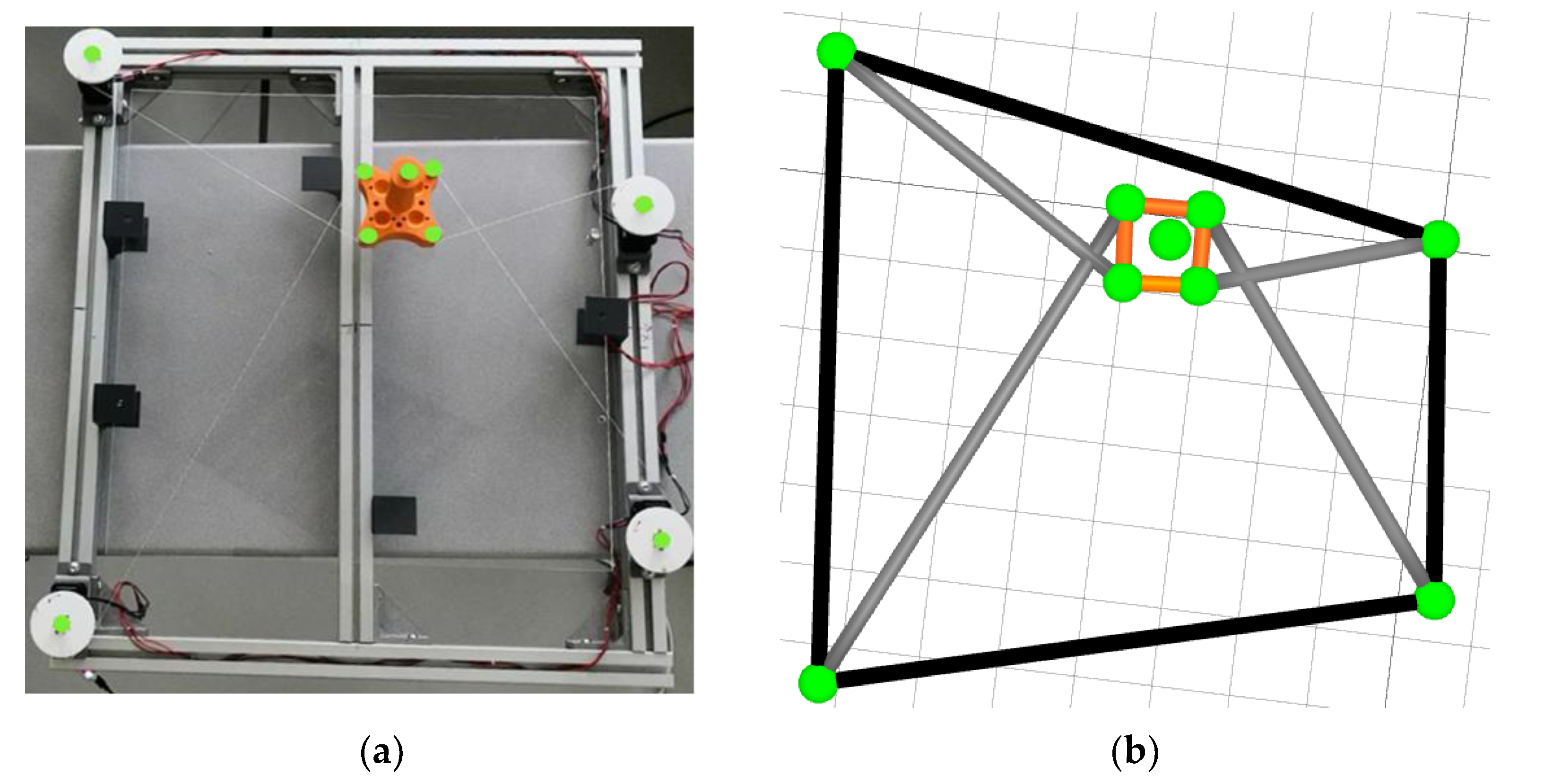
4. Experimental Validation

Following the optimization study detailed above, a CDPR prototype, presented in Figure 11a, was developed. The actuators’ positions and the end-effector size were adjusted according to the optimal design vector resulting in Table 2. It was composed of a rigid frame with four actuated pulleys controlling the end-effector poses by means of four cables. The patient sits near to the robot and grabs the mobile platform with his hand. Figure 11b shows the prototype representation using QTM (Qualisys Track Manager) software recording the passive markers’ locations along the end-effector movement.
The prototype was actuated using the Dynamixel MX-106T and equipped with a feedforward, a PID controller and a gear reducer. The pulleys and the end-effector were produced using 3D printing. The cables were made of Dacron.
The extended position control mode was used for the actuator commands. The desired angular positions of the motors were computed using the inverse kinematic model. Figure 12 presents the block diagram of the robot control.
The angular positions of the pulleys were controlled so that the robot end-effector could replicate the prescribed exercise. A motion capture system was also used in this phase to evaluate the performance of the robot by tracking the mobile platform poses along its movement so that a comparison, illustrated in Figure 13, between the target and the performed trajectories could be made. This external and global approach allowed consideration of all error sources inside and outside the control loop, such as anchor point errors and the cable’s behavior.
In order to assess the robot prototype performance, the mean absolute, the root-mean-square and the standard deviation position and orientation errors were computed as given in Table 4.
Where X t ( i ) and X m ( i ) are the true and the measured values corresponding to the i t h position, ϵ ( i ) = X t ( i ) X m ( i ) is the measured error at the i t h position, ϵ ¯   is the mean of ϵ and n is the number of points forming the trajectory.

5. Conclusions

This paper aims to find the optimal design of a planar cable-driven parallel robot for upper limb rehabilitation purposes. For that, an optimization problem was formulated in which the dexterity, the elastic stiffness and the tension in the cables were the chosen criteria. Bounding the cable tensions, avoiding collisions with the mobile platform and controlling the potential positions of the pulleys were the selected constraints. A multi-objective formulation of the optimization design problem showed different nondominated solutions for each pair of criteria, which complicated the selection of a single solution. A mono-objective formulation was then adopted. Weighting coefficients were studied, and appropriate values were selected. Finally, the validation of the robot optimal design was carried out using a real prototype to verify its behavior along the given trajectory. Different computed errors between the desired and the performed trajectories showed promising results regarding prototype reliability.

Author Contributions

Conceptualization, methodology, supervision, writing—review and editing, M.A.L., A.C., J.S., A.M., L.R., S.B., and S.Z.; software and writing—original draft preparation, F.E.; project administration, M.A.L., and A.C. All authors have read and agreed to the published version of the manuscript.

Funding

This work was financially supported by the PHC Utique program of the French Ministry of Foreign Affairs and Ministry of higher education, research and innovation and the Tunisian Ministry of higher education and scientific research in the CMCU, project number 19G1121.

Institutional Review Board Statement

Not applicable.

Informed Consent Statement

Informed consent was obtained from all subjects involved in the study.

Data Availability Statement

Data is contained within the article.

Conflicts of Interest

The authors declare no conflict of interest.

References

  1. Babaiasl, M.; Mahdioun, S.H.; Jaryani, P.; Yazdani, M. A review of technological and clinical aspects of robot-aided rehabilitation of upper-extremity after stroke. Disabil. Rehabil. Assist. Technol. 2016, 11, 263–280. [Google Scholar] [CrossRef] [PubMed]
  2. Khan, S.B.; Rahman, M.H.; Haque, M.O.; Rahman, E. Effectiveness of Task Oriented Physiotherapy Along with Conventional Physiotherapy for Patients with Stroke. IJNPT 2019, 5, 37–41. [Google Scholar] [CrossRef]
  3. Le Guiet, J.L.; Le Claire, G. Pendant combien de temps doit-on pratiquer la rééducation du membre supérieur chez l’hémiplégique? Ann. Réadaptation Méd. Phys. 1998, 41, 107–113. [Google Scholar] [CrossRef]
  4. Prange, G.B.; Jannink, M.J.A.; Groothuis-Oudshoorn, C.G.M.; Hermens, H.J.; Ijzerman, M.J. Systematic review of the effect of robot-aided therapy on recovery of the hemiparetic arm after stroke. JRRD 2006, 43, 171–184. [Google Scholar] [CrossRef] [Green Version]
  5. Gassert, R.; Dietz, V. Rehabilitation robots for the treatment of sensorimotor deficits: A neurophysiological perspective. JNER 2018, 15, 1–15. [Google Scholar] [CrossRef] [PubMed] [Green Version]
  6. Garcia, D.A.; Arredondo, R.; Morris, M.; Tosunoglu, S. A review of rehabilitation strategies for stroke recovery. In Proceedings of the ASME Early Career Technical Conference, Atlanta, Georgia, USA, 2–3 November 2012; Volume 11, pp. 24–31. [Google Scholar]
  7. Oña, E.D.; Cano-de La Cuerda, R.; Sánchez-Herrera, P.; Balaguer, C.; Jardón, A. A review of robotics in neurorehabilitation: Towards an automated process for upper limb. J. Healthc. Eng. 2018, 2018. [Google Scholar] [CrossRef]
  8. Maciejasz, P.; Eschweiler, J.; Gerlach-Hahn, K.; Jansen-Troy, A.; Leonhardt, S. A survey on robotic devices for upper limb rehabilitation. JNER 2014, 11, 1–29. [Google Scholar] [CrossRef] [Green Version]
  9. Qassim, H.M.; Wan Hasan, W.Z. A Review on Upper Limb Rehabilitation Robots. Appl. Sci 2020, 10, 6976. [Google Scholar] [CrossRef]
  10. Nef, T.; Riener, R. ARMin-design of a novel arm rehabilitation robot. In 9th ICORR; IEEE: Chicago, IL, USA, 2005; pp. 57–60. [Google Scholar] [CrossRef]
  11. Reinkensmeyer, D.J.; Kahn, L.E.; Averbuch, M.; McKenna-Cole, A.; Schmit, B.D.; Rymer, W.Z. Understanding and treating arm movement impairment after chronic brain injury: Progress with the ARM guide. JRRD 2000, 37, 653–662. [Google Scholar]
  12. Lum, P.S.; Burgar, C.G.; Van der Loos, M.; Shor, P.C.; Majmundar, M.; Yap, R. MIME robotic device for upper-limb neurorehabilitation in subacute stroke subjects: A follow-up study. J. Rehabil. Res. Dev. 2006, 43, 631. [Google Scholar] [CrossRef]
  13. Xiong, H.; Diao, X. A review of cable-driven rehabilitation devices. Disabil. Rehabil. Assist. Technol. 2020, 15, 885–897. [Google Scholar] [CrossRef]
  14. Qian, S.; Zi, B.; Shang, W.W.; Xu, Q.S. A Review on Cable-driven Parallel Robots. Chin. J. Mech. Eng. 2018, 31, 66. [Google Scholar] [CrossRef]
  15. Scalera, L.; Gasparetto, A.; Zanotto, D. Design and experimental validation of a 3-dof underactuated pendulum-like robot. IEEE ASME Trans. Mechatron. 2019, 25, 217–228. [Google Scholar] [CrossRef]
  16. Ji, H.; Shang, W.; Cong, S. Adaptive Control of a Spatial 3-Degree-of-Freedom Cable-Driven Parallel Robot with Kinematic and Dynamic Uncertainties. In Proceedings of the 2020 5th International Conference on Advanced Robotics and Mechatronics (ICARM 2020), Shenzhen, China, 14 September 2020; pp. 142–147. [Google Scholar] [CrossRef]
  17. Mottola, G.; Gosselin, C.; Carricato, M. Dynamically-feasible elliptical trajectories for fully constrained 3-DOF Cable-suspended parallel robots. In Cable-Driven Parallel Robots; Springer: Cham, Switzerland, 2018; pp. 219–230. [Google Scholar] [CrossRef]
  18. Xiang, S.; Gao, H.; Liu, Z.; Gosselin, C. Dynamic transition trajectory planning of three-DOF cable-suspended parallel robots via linear time-varying MPC. Mech. Mach. Theory 2020, 146, 103715. [Google Scholar] [CrossRef]
  19. Gagliardini, L.; Caro, S.; Gouttefarde, M.; Wenger, P.; Girin, A. Optimal design of cable-driven parallel robots for large industrial structures. In Proceedings of the ICRA 2014, Hong Kong, China, 31 May–7 June 2014; pp. 5744–5749. [Google Scholar] [CrossRef] [Green Version]
  20. Hussein, H.; Santos, J.C.; Gouttefarde, M. Geometric Optimization of a Large Scale CDPR Operating on a Building Façade. In Proceedings of the IROS 2018, Madrid, Spain, 1–5 October 2018; pp. 5117–5124. [Google Scholar] [CrossRef] [Green Version]
  21. Fattah, A.; Agrawal, S.K. On the Design of Cable-Suspended Planar Parallel Robots. J. Mech. Des. 2005, 127, 1021–1028. [Google Scholar] [CrossRef]
  22. Li, Y.; Xu, Q. GA-Based Multi-Objective Optimal Design of a Planar 3-DOF Cable-Driven Parallel Manipulator. In Proceedings of the IEEE Robio 2006, Kunming, China, 17–20 December 2006; pp. 1360–1365. [Google Scholar] [CrossRef]
  23. Chaparro-Rico, B.D.M.; Cafolla, D.; Castillo-Castaneda, E.; Ceccarelli, M. Design of arm exercises for rehabilitation assistance. J. Eng. Res. 2020, 8, 204–218. [Google Scholar] [CrossRef]
  24. Kawamura, S.; Ito, K. A new type of master robot for teleoperation using a radial wire drive system. In Proceedings of the IROS 1993, Yokohama, Japan, 26–30 July 1993; pp. 55–60. [Google Scholar] [CrossRef]
  25. Lee, J.H.; Eom, K.S.; Suh, I.I. Design of a new 6-DOF parallel haptic device. In Proceedings of the ICRA 2001, Seoul, Korea, 21–26 May 2001; Volume 1, pp. 886–891. [Google Scholar] [CrossRef]
  26. Ma, O.; Angeles, J. Optimum architecture design of platform manipulators. In Proceedings of the 5th ICARR ’Robots in Unstructured Environments, Atlanta, GA, USA, 2–6 May 1993; Volume 2, pp. 1130–1135. [Google Scholar] [CrossRef]
  27. Khan, S.; Andersson, K.; Wikander, J. Jacobian Matrix Normalization—A Comparison of Different Approaches in the Context of Multi-Objective Optimization of 6-DOF Haptic Devices. J. Intell. Robot. Syst. 2015, 79, 87–100. [Google Scholar] [CrossRef]
  28. Gunantara, N. A review of multi-objective optimization: Methods and its applications. Cogent Eng. 2018, 5, 1502242. [Google Scholar] [CrossRef]
  29. Jia, J.; Fischer, G.W.; Dyer, J.S. Attribute weighting methods and decision quality in the presence of response error: A simulation study. J. Behav. Decis. Mak. 1998, 11, 85–105. [Google Scholar] [CrossRef]
  30. Dawes, R.M.; Corrigan, B. Linear models in decision making. Psychol. Bull. 1974, 81, 95. [Google Scholar] [CrossRef]
  31. Einhorn, H.J.; McCoach, W. A simple multiattribute utility procedure for evaluation. Behav. Sci. 1977, 22, 270–282. [Google Scholar] [CrossRef]
  32. Ferdaws, E.; El Golli, H.; Chaker, A.; Laribi, M.A.; Sandoval, J.; Bennour, S.; Mlika, A.; Romdhane, L.; Zeghloul, S. Design Optimization and Dynamic Control of a 3-d.o.f. Planar Cable-Driven Parallel Robot for Upper Limb Rehabilitation. In Proceedings of the New Trends in Medical and Service Robotics MESROB, Virtual Conference, 7–9 June 2021. [Google Scholar]
  33. Eberhart, R.; Kennedy, J. A new optimizer using particle swarm theory. In Proceedings of the Sixth International Symposium on Micro Machine and Human Science MHS’95, Nagoya, Japan, 4–6 October 1995; pp. 39–43. [Google Scholar] [CrossRef]
  34. Sands, T. Optimization provenance of whiplash compensation for flexible space robotics. Aerospace 2019, 6, 93. [Google Scholar] [CrossRef] [Green Version]
  35. Shorman, S.M.; Pitchay, S.A. Significance of parameters in genetic algorithm, the strengths, its limitations and challenges in image recovery. ARPN J. Eng. Appl. Sci. 2006, 10, 585–593. [Google Scholar]
Figure 1. (a) Motion capture setup; (b) Marker locations.
Applsci 11 05635 g001
Figure 2. Data acquisition steps.
Applsci 11 05635 g002
Figure 3. Local and global frames.
Applsci 11 05635 g003
Figure 4. (a) Hand trajectory (composed of 331 equidistant points); (b) hand orientation. “+” denotes the starting and the ending position.
Applsci 11 05635 g004
Figure 5. Geometric representation of the planar robot.
Applsci 11 05635 g005
Figure 6. The Pareto front.
Applsci 11 05635 g006
Figure 7. Bi-objective visualizations of the Pareto front.
Applsci 11 05635 g007
Figure 8. Variation of (a) the cable tension criterion, (b) the elastic stiffness criterion, (c) the dexterity criterion and (d) the objective function along the prescribed movement vs β 1 and β 2 ( β 3 = 1 ( β 1 + β 2 ) ).
Applsci 11 05635 g008
Figure 9. Optimization results (a) the cable tension distribution, (b) the elastic stiffness distribution, (c) the dexterity distribution along the task workspace and (d) the arrows signification represented in (ac).
Applsci 11 05635 g009aApplsci 11 05635 g009b
Figure 10. The free collision static workspace (in blue) for (a) Φ =   Φ m i n =   13 ° , (b) Φ = 0 ° and (c) Φ =   Φ m a x =   24 ° .
Applsci 11 05635 g010aApplsci 11 05635 g010b
Figure 11. (a) Robot prototype and (b) its representation using QTM (Qualisys Track Manager) software. Markers are represented in green.
Applsci 11 05635 g011
Figure 12. Control block diagram.
Applsci 11 05635 g012
Figure 13. Variations between the desired and the real (a) trajectories and (b) orientations.
Applsci 11 05635 g013
Table 1. Optimization problem parameters.
ParameterValue
Mobile platform weight [kg]0.5
Pulley radius [mm]37
Cable radius [mm]0.3
T m i n [N]0.5
T m a x [N]15
α l i m [°]2
β 1 = β 2 0.45
β 3 0.1
Population size100
Table 2. Boundaries of the design parameters.
Parameter a 1 b 1 a 2 b 2 a 3 b 3 a 4 b 4 c
Lower bounds [m]−0.375−0.3850−0.38500−0.37500.1
Upper bounds [m]000.37500.3750.38500.3850.15
Table 3. Optimization results.
ParameterValue
Optimal design vector I [ 0.375 , 0.39 ,   0.375 , 0.26 ,   0.375 ,   0.18 , 0.375 ,   0.39 ,   0.1 ]
Objective function 0.35
Cable tension criterion C 1 0.124
Elastic stiffness criterion C 2 0.588
Dexterity criterion C 3 0.3
Table 4. Measured errors between the desired and the performed end-effector poses.
ParameterEquationValue
Mean absolute error 1 n i = 1 n | X t ( i ) X m ( i ) | Position [mm]10.63
Orientation [°]1.64
Root-mean-square error i = 1 n ( X t ( i ) X m ( i ) ) 2 n Position [mm]13
Orientation [°]1.95
Error standard deviation i = 1 n ( ϵ ( i ) ϵ ¯   ) 2 n 1 Position [mm]12.57
Orientation [°]1.06
Publisher’s Note: MDPI stays neutral with regard to jurisdictional claims in published maps and institutional affiliations.

