Article

A Parametric Product Design Framework for the Development of Mass Customized Head/Face (Eyewear) Products

1
School of Art and Design, Xi’an University of Technology, Xi’an 710048, China
2
Department of Architecture and 3D Design, School of Art, Design and Architecture, University of Huddersfield, Huddersfield HD1 3HB, UK
*
Author to whom correspondence should be addressed.
Appl. Sci. 2021, 11(12), 5382; https://doi.org/10.3390/app11125382
Submission received: 27 April 2021 / Revised: 29 May 2021 / Accepted: 7 June 2021 / Published: 10 June 2021
(This article belongs to the Topic New Frontiers in Industry 4.0)

Abstract

:
This study led to the development of a parametric design method for mass-customised head/face products. A systematic review of different approaches for mass customization was conducted, identifying advantages and limitations for their application to new product development. A parametric modelling algorithm of a 3D human face was developed using selected scanned 3D head models. The algorithm was developed from a set of measurable and adjustable parameter points related to the facial geometry. These parameters were defined using planimetry. Using the assigned parameter values as input, the parametric model generated 3D models of a human face that served as a reference for the design of customized eyewear. The current challenges and opportunities of mass customized head/face products are described, along with the possibilities for new parametric product design approaches to enable rapid manufacturing and mass customization. This study also explored whether a new parametric design framework for mass customization could be effectively implemented as an early-stage new product development strategy for head/face products.

1. Introduction

Science and technology continue to rapidly develop, with businesses moving faster toward smart manufacturing during the so-named 4th Industrial Revolution. There is a constant demand for specialized products, where customization is becoming prevalent, and where standard available tools are applied in a flexible but effective way within the product design process. Market demand is constantly changing, leaving the industry and designers with the task to develop new and flexible approaches to meet users’ needs. For example, wearable products and automotive components are particularly a good exemplar of how small-batch and customized production has been used as a strategy to quickly deliver personalized products to gradually replace mass-produced products [1,2]. Usually, customization is applied during the manufacturing of a product by adjusting certain product elements rather than restarting the entire production to deliver a new product variation. In this context, customization allows enterprises to adapt to the always-changing customer needs and act accordingly, hence offering a key indicator to measure sustainable economic development.
Product personalization and design for Mass Customization (MC) have been used by product designers as strategies to adapt to the always changing users’ needs. MC calls for flexibility and quick responsiveness in a context with ever-changing factors (i.e., people’s needs, market, and processes and technology) to provide customer satisfaction through an increased product variety with a limited effect in cost and lead time, contrary to the old paradigm of mass production (i.e., mass-produced standardized products). MC has had a great appeal to industry and academia during recent years, and some frameworks have been proposed to effectively achieve MC through design. The implementation of MC frameworks during the conceptual design and preliminary development stages has led to the adaptive concept of Design for Mass Customization (DFMC) [3].
Design as discipline and thinking process has an important role at the fuzzy front end (FFE) of innovation and at new product development [4]. Whether or not MC is implemented as a key element in the innovativeness of a product or service, it is perhaps at the FFE of innovation when it can be considered as part of the product strategy [3]. Therefore, this work approaches the MC framework from the Product Design perspective, and at an early stage of the New Product Development (NPD) process [5].
In product design, customization has played an important role in the good fit and comfortability of wearable products, hence its use as a way to improve product ergonomics. Some studies have shown that MC capability can be developed using modular systems and innovative product designs and processes [6,7,8]. Additionally, MC has allowed large companies to integrate customers into the design process [9]. However, this process relies on the exploration and visualization of the different existing eyewear models to assist customers in the collaborative process. On the other hand, smaller eyewear companies approach customization through the implementation and continuous optimization of flexible tools within the manufacturing process [10].
This study proposes an MC design framework based on a comparative study of current 3D data acquisition methods and a parametrized design approach that can be used at the early stages of eyewear design to provide a more attainable MC and co-design experience. In this work, a typical eyewear design is used as a case study to explore the development of the aforementioned MC framework. This framework is developed from a product design perspective, trying to implement such workflow at the FFE stage of NPD, where flexibility in the creative process is a key factor for the product designer, as well, as comfortability, good fit, and customization are Unique Selling Points (USPs) and decision-making factors for the customer.

2. Related Works

2.1. Mass Customisation, Personalisation and Design

Within the context of this study, MC is referred as the use of flexible computer-aided design and manufacturing systems to produce customized products for mass production purposes. One of the main objectives of an MC strategy is to obtain the low unit costs that benefit from a mass production process and the flexibility of customization. MC gives customers and industry the chance to interact across the different stages of the NPD process, allowing the manufacturer to satisfy the customer’s specific needs [11]. On the other hand, personalization as an industrial strategy approaches each customer satisfaction as an individual entity. Therefore, product differentiation occurs at the same individual level, whereas customization differentiates products for market segments. Making profit and gaining competitiveness through product differentiation is not new; companies are continuously using market segmentation or customer-centred personalization strategies to remain competitive.
Different MC methodologies and strategies have been developed, and different levels of customization have been proposed [12]. The combination of these frameworks has led to eight generic levels of MC, ranging from pure customization (individually designed products) to pure standardization, where design (from a project point of view) appears at the top of the levels [11]. Furthermore, MC can be implemented at different stages along the value chain and product development process, from the total customization of a product’s design, manufacturing, assembly, delivery and even sale, up to the simplest interventions/adaptations of products by customers.
According to the four levels of customization proposed by Gilmore and Pine, a collaborative and transparent customization should foster designers’ dialogue with customers, thereby products can be easily adapted to individual user needs [13]. Moreover, Design Customization (DC) refers to a collaborative project (i.e., design), manufacturing and delivery of products according to individual user needs and preferences (i.e., intrinsic and extrinsic).
In terms of design, customization classifies customers into market segments based on the needs identified by market analysis. Consequently, customers within a designated segment receive a similar or parameter-based customized product. This customized product keeps the pre-configured elements stable (i.e., configuration mechanism, product architectures, basic modules). Therefore, the principle of Design for Mass Customization is to be able to create many product variations through the configuration of modular elements using the commonality embedded within the designed product platform so that these modular elements can be reused among the different product families [5,11]. On the contrary, in Design for Mass Personalization (DFMP), industry works along with customers to create products that may be completely new to fulfil customer needs within a given budget and time constraints. In this case, personalization enables product differentiation beyond the original set of product offerings. Nevertheless, it remains a difficult task to design a product intended to be mass-customized.
Customization implies the use of fixed and predefined product elements, whereas personalization allows changes to the basic design and product features. The flexibility of a product design in terms of its adaptability to changes is essential for personalization and customization as the main objective of product design and is the meet-up of customer needs [14]. Customization allows users to select from a predetermined set of already proven elements that will logically configure a product. Designers define in advance the product elements that could potentially be used to create a different range of products based on user/customer needs. This set of elements is based on qualitative and quantitative requirements carefully obtained from users or other stakeholders [15,16,17]. Therefore, the product design process plays a fundamental role in determining the elements that will be common between the building blocks that customers will use to create product predictably. On the other hand, personalization is less predictable, as it gives users the chance to foresee the product result within the company. Hence, the importance of an innovative design framework that considers the user experience of designers to carry out with efficiency the DFMC or DFMP process.

2.2. Customer-Driven Design and Manufacture at the Core of MC Systems

Customers’ preferences are critical to product development [18]. To enable and fully support the development of a successful MC system, the main elements of a manufacturing strategy along with the user/customer preferences need to be considered [11]. These are included within the following:
  • Agile manufacturing is the ability to thrive and prosper in a competitive environment of continuous and unanticipated change in order to respond quickly to rapidly changing markets driven by customer-based valuing of products [19]. Here, it is important to truly capture user preferences and requirements based on attitudes and emotions, which may imply further challenges [17].
  • Supply-chain management concerns the coordination of resources and the optimisation of activities across the value chain to obtain competitive advantages [20,21]
  • Customer-driven design and manufacture at the core of MC systems [22] “actively considers the market trends and individual customer requirements during the design, manufacturing and delivery of the products”. Some authors call this practice “One-of-a-Kind Production” (OKP). The application of customer-driven practices in MC systems aims at providing the conditions for the customer to take part in the design process, and for the company to build an infrastructure to develop such customer-driven products, hence the relevance of defining customer preferences though a robust design requirement specification [15].
  • Lean manufacturing is an efficient way to satisfy customer needs while giving producers a competitive edge [23]. MC production addresses four elements of lean production: product development, the chain of supply, shop floor management, and after-sales services [24].
The main enabling technologies supporting MC can include additive manufacturing (AM) [25], computer numeric control (CNC) [11], flexible manufacturing systems (FMS) [26], computer-aided design (CAD) [27], computer-aided manufacturing (CAM), computer-integrated manufacturing (CIM), and electronic data interchange (EDI) [28]. The use of these technologies is justified by their inherent flexibility, and their capability to alter the economies of manufacturing and remove barriers to product variety. Additionally, these technologies allow full exploitation of the fundamental MC attributes such as agility and flexibility.

2.3. The Ergonomic-Anthropometric-Good Fit Relationship

Most of the eyewear products that can be found in the market are mass-produced products. Their design follows current trends and “standard” anthropometric dimensions to make the final product suitable to user needs. A good fit–comfortability relation is an important decision-making factor in the purchase process for this type of product. However, age, head asymmetry, and evolutive body size change are usually not considered in the design of these mass-produced products. Some studies have already made clear the head and face size differences between race, gender, and age. For example, the head size changes at different ages have been analyzed through a long-term observation [29]. Face morphology and size differences between genders, races and populations have also been described based on statistical principles [30] and comparison studies [31]. Ball et al., on the other hand, used the data from the North American and European Caucasians (CAESAR) and the SizeChina human body databases, to analyze and compare the head size differences between Caucasian and Chinese people [32]. Hanson et al. found many body size changes on workers after collecting 3D data of 367 volunteers’ bodies and comparing results with original ergonomic data [33]. This ergonomic–anthropometric good fit relationship is a field that has intrigued many scholars. Some have taken an approach of statistically analyzing anthropometric data [34,35,36] to generate tools that designers could use to establish product size systems [37]. On the other hand, a parametric-based system has also been used to cluster anthropometric head-size data sets into four major groups, providing with this the basis for a personalized bicycle helmet design [38]. Nevertheless, due to the complexity and diversity of human head morphology, it remains difficult to design personalized and customized products within a flexible design framework.

2.4. 3D Scanning Technology

New design and manufacturing technologies such as generative design, 3D scanning, and additive manufacturing have expanded the possibilities for companies that are dealing with MC or personalized products [11,39,40]. 3D Scanning technologies have offered a more reliable and efficient method for obtaining accurate 3D measurements and morphological data to design more appropriate products, where a good fit is of paramount importance [41]. For example, Luximon et al. used collected 3D data of men’s and women’s heads from different regions of China to provide an accurate representation of a 3D head and face shape with corresponding anatomical features for product design and evaluation [42,43]. Zheng et al. also used 3D scanning to develop a new measuring system [36]. However, due to the complexity the human body presents, it is difficult to accurately represent its morphology with the current diversity of parameters [33,35,44].

2.5. Wearable Product Design
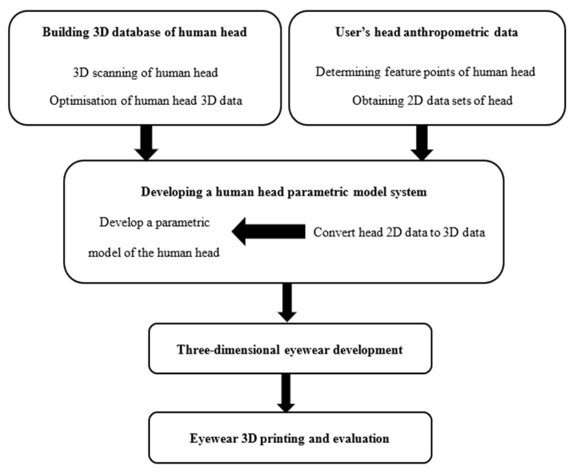
The appropriate definition of human body parameters for product design is particularly important for products that require a good fit and comfort such as helmets or earphones [45,46]. Design methods have linked these parameters to the human body’s 3D models to achieve a good product fit [47,48]. CAD software packages have allowed designers to create products based on parametric systems. These systems can refer directly to a 3D measured human body to explore the design of the product following real-time ergonomic and anthropometric parameters being used [49]. For example, Rhinoceros 3D software is a commercial 3D modelling software developed by Robert McNeel & Associates that is widely used. The software offers a tool to approach the whole design process, from design sketch to actual product. Rhinoceros 3D geometry uses Non-Uniform Rational B-Splines (NURBS) producing mathematically precise curves and freeform surfaces. The software can accurately generate 3D models for design, development rendering, animation, engineering drawing, analysis and evaluation, prototyping, and production. Moreover, Rhinoceros’ plug-in Grasshopper allows the software to generate parametric models based on visual programming language, therefore offering a flexible parametric design application based on visual programming and data flow [50]. Other NURBS-based concept modelling packages include Alias, ICEM surf from Dassault Systèmes, and many other polygonal-based tools such as Blender, Seamless3d and Maya. Some of these 3D software packages offer visual programming tools (e.g., Grasshopper and Dynamo). These visual programming tools are popular among designers, architects, engineers, artists, and manufacturers, due to the quick iterative processes used with minimal knowledge of programming.
As a typical wearable product, eyewear has also attracted the attention of some researchers. Some have used 3D scanning models and the principal-component analysis method to reduce the complexity of 3D data, as well as the definition of key partial feature points that correlate between the different parameters using a Kringing nonlinear regression method, consequently generating a new 3D face model that was used to create personalized eyewear designs [51]. On the other hand, virtual reality and semantic parameters have also been used to bring real-time design interactivity between users and designers [52]. In addition, Weihua Lu has used the emotion expressed in the voice as a 3D modelling or design parameter that could be used to personalize eyewear [53]. Some of the work reviewed focuses on the virtual trial/wearing of eyewear and the apparent relation between product size and the human face, limiting the work to the visual perception of good fit or to the design of eyewear based on the acquisition of statistical data from face size, consequently focusing on the predetermined appearance or aesthetic features of eyewear, but not on the comfort and the meeting of individual consumer preferences.
Eyewear products may need to be worn every day, and comfortability is a concern for consumers. However, the design and manufacturing of eyewear is a long and complex process, and the comfort of this large-scale manufactured product does not always meet the needs of some consumers. Therefore, research on personalized design of eyewear becomes valuable for both consumer and industry, potentially improving many related aspects of the product such as aesthetics and ergonomics, whilst taking advantage of current manufacturing technologies, materials, and methods for eyewear products.
In this paper the authors propose a new framework to approach the creation of eyewear, based on algorithmic and parametric CAD software to provide an effective design tool that allows the customization or personalization of this type of product. This method attempts to obtain the user’s head size through two orthogonal photos to then establish a 3D parametric head model to build a fully customizable eyewear 3D model. This work covers a preliminary evaluation of three scanning methods used to capture head/face features (i.e., photogrammetry, somatosensory and laser scanning) and the development of a parametric-based strategy for the design of personalized eyewear.

3. Methodology

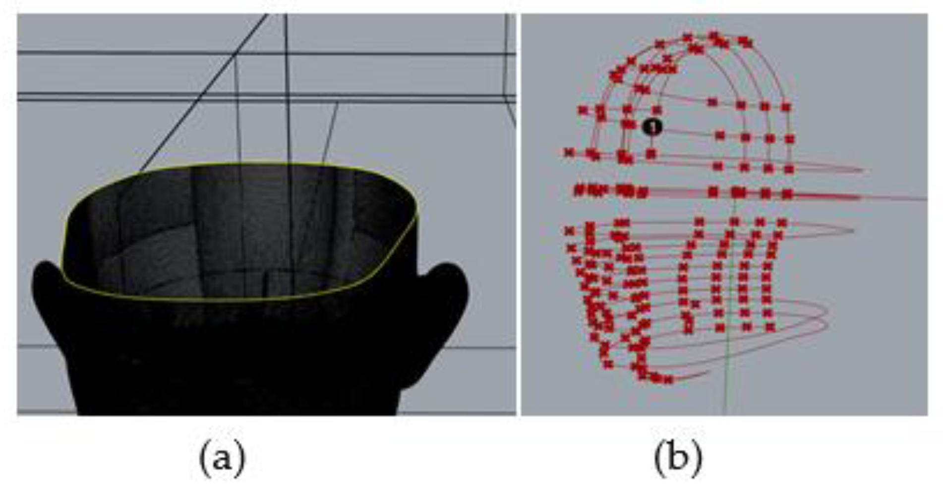
3.1. Parametric Modelling Strategy

An overview of the methodology used is presented in Figure 1. In the current work, by collecting three-dimensional scan data of the human head, and based on principal component analysis and the K clustering algorithm, the head model was divided into several regions to generate a three-dimensional model, to then establish a head model database. This method is based on work previously published [43,44,52,54]. According to the feature points of the head, the 3D scanning model was sliced/divided, and the contour line was then extracted. By using the interpolation method, where 24–26 points were used to obtain an interpolation curve similar to the contour line, the hierarchical interpolation curve was used to create the head parametric model. Orthogonal photographs were then used to develop a two-dimensional (2D) image-based reading system to determine head/face feature points. These 2D data points obtained from the orthogonal images were transformed into 3D data that was used as an input to create the corresponding human head parametric model. Following this, the parametric 3D model was used as a referencing system where the parametric eyewear was designed. Finally, using 3D printing, the designed eyewear product was prototyped to evaluate comfort and fit.

3.2. Head/Face Scanning

Before developing the 3D parametric model of the head, 3D scanning methods were evaluated to determine their suitability for this study. Convenience, speed, and accuracy were used as the main evaluation parameters.

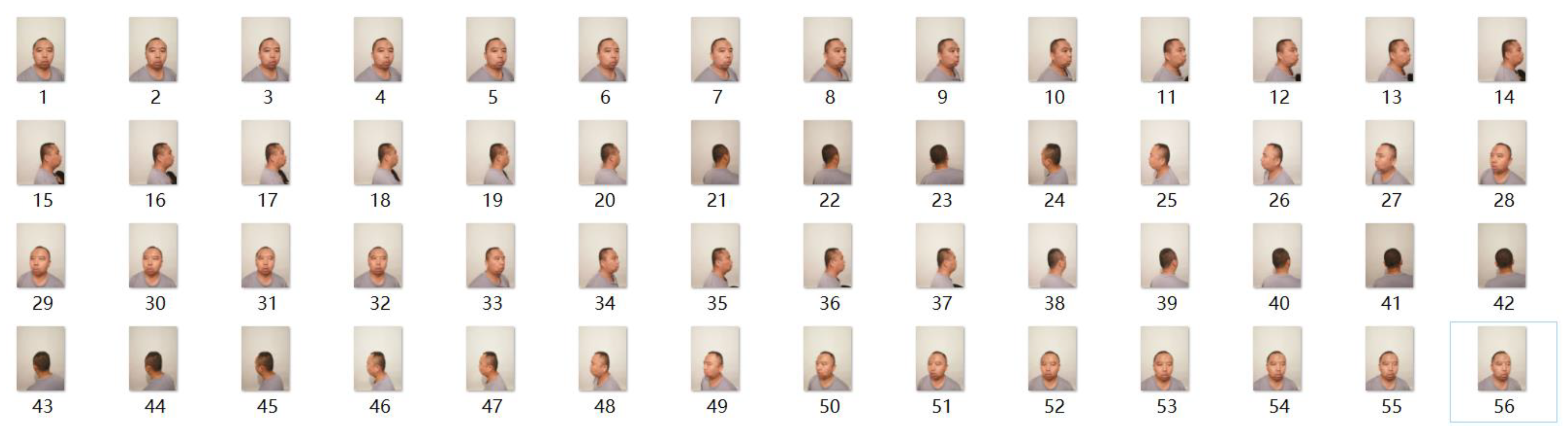
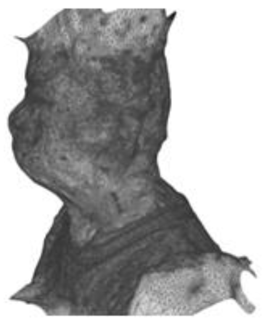
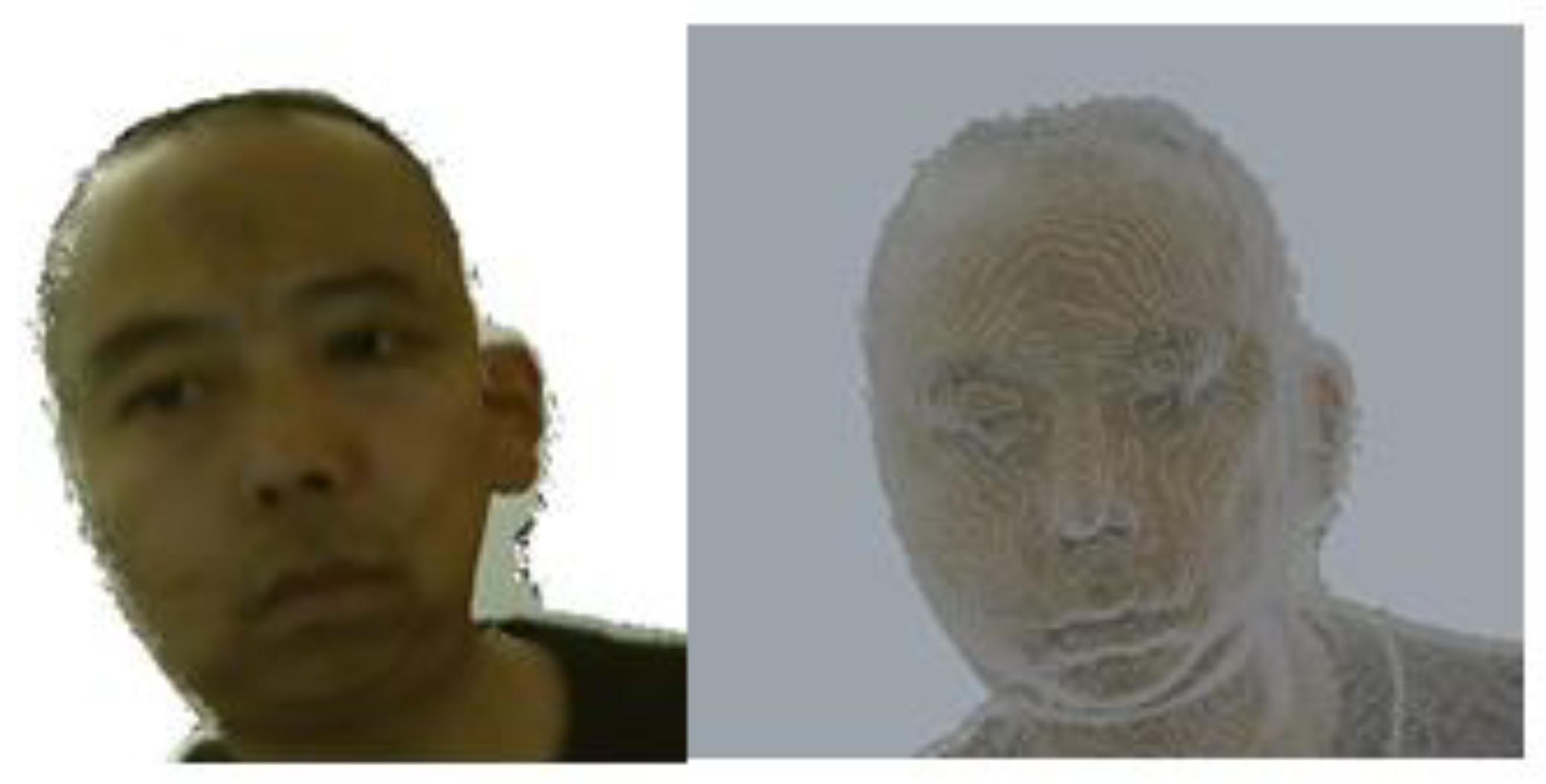
3.2.1. Photogrammetry

Photogrammetry is based on the principle of a camera imaging system; it uses multiple photos from different angles to reconstruct a 3D model. This usually includes the following steps: image characteristics extraction, depth restoration, point cloud registration, and deep integration [55]. This method is mainly used by surveyors, architects, engineers, and contractors to create topographic maps, meshes, point clouds or drawings. For this method, 56 high-resolution images were taken from 360° whilst the user remained still in front of a plain background and without any objects to obstruct the view. The high-resolution images were then processed using a photogrammetry application to generate a human head 3D model (see Figure 2).

3.2.2. Somatosensory Camera Scan

A somatosensory controller, such as Kinect from Microsoft(Redmond, WA, USA), comprises three lenses (RGB), an infrared transmitter, and an infrared receiver. This system has been used as a low-cost (under $200) scanning alternative. The Kinect can simultaneously obtain the depth image and RGB image from the object, consequently making it possible to obtain an accurate 3D model with original colours. In this method, the scanning device was mounted on a tripod while the subject remained still on a platform that slowly rotated 360° during the capturing. Scanning accuracy was continuously adjusted to the scanning distance to obtain the best scanning results.

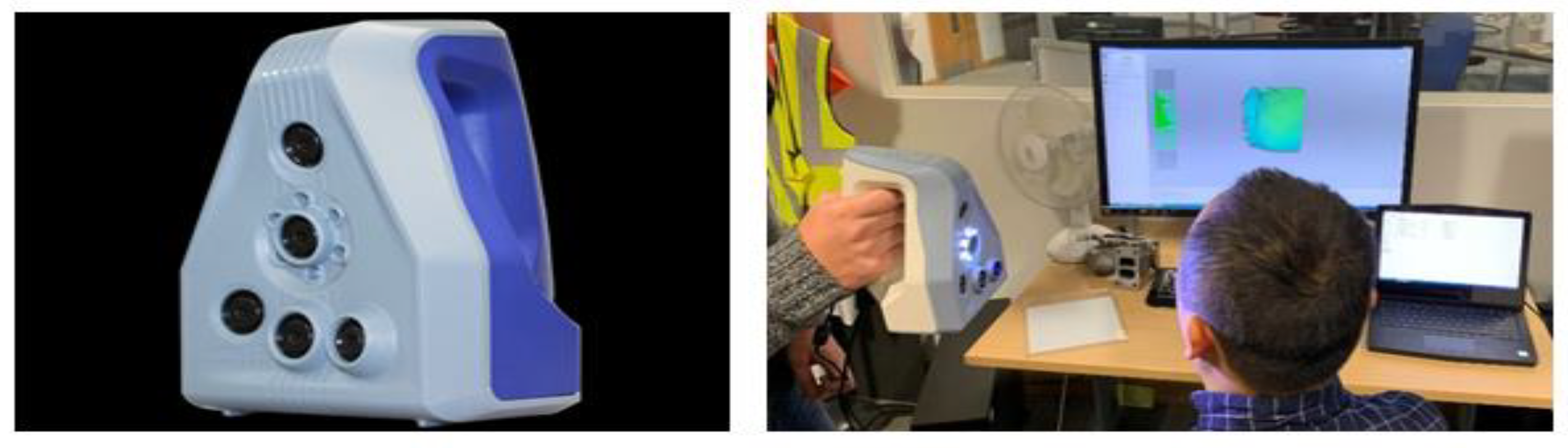
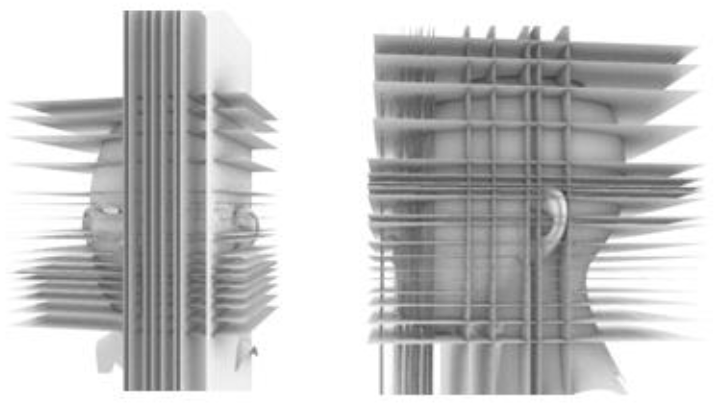
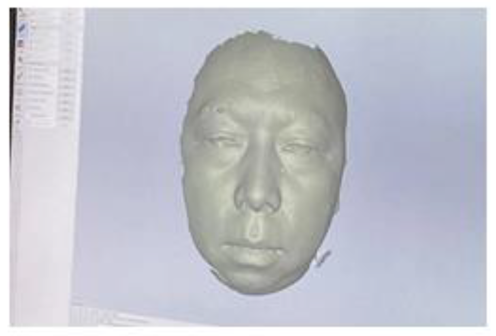
3.2.3. Laser Scanning

There are a variety of small and portable 3D scanners used for different applications. Their accuracy is generally high although not as high as Coordinate Measuring Machines (CMM). Due to their accuracy, light weight, and portability, the Space Spider scanner (Artec 3D, Luxembourg) was selected for evaluation (see Figure 3). A quick scan of a small object with enough details would normally take 5–10 min. Several 3D full head/face scans were captured, and resulting scans were then validated against the localization of key feature points and measurements taken from orthogonal photographs.

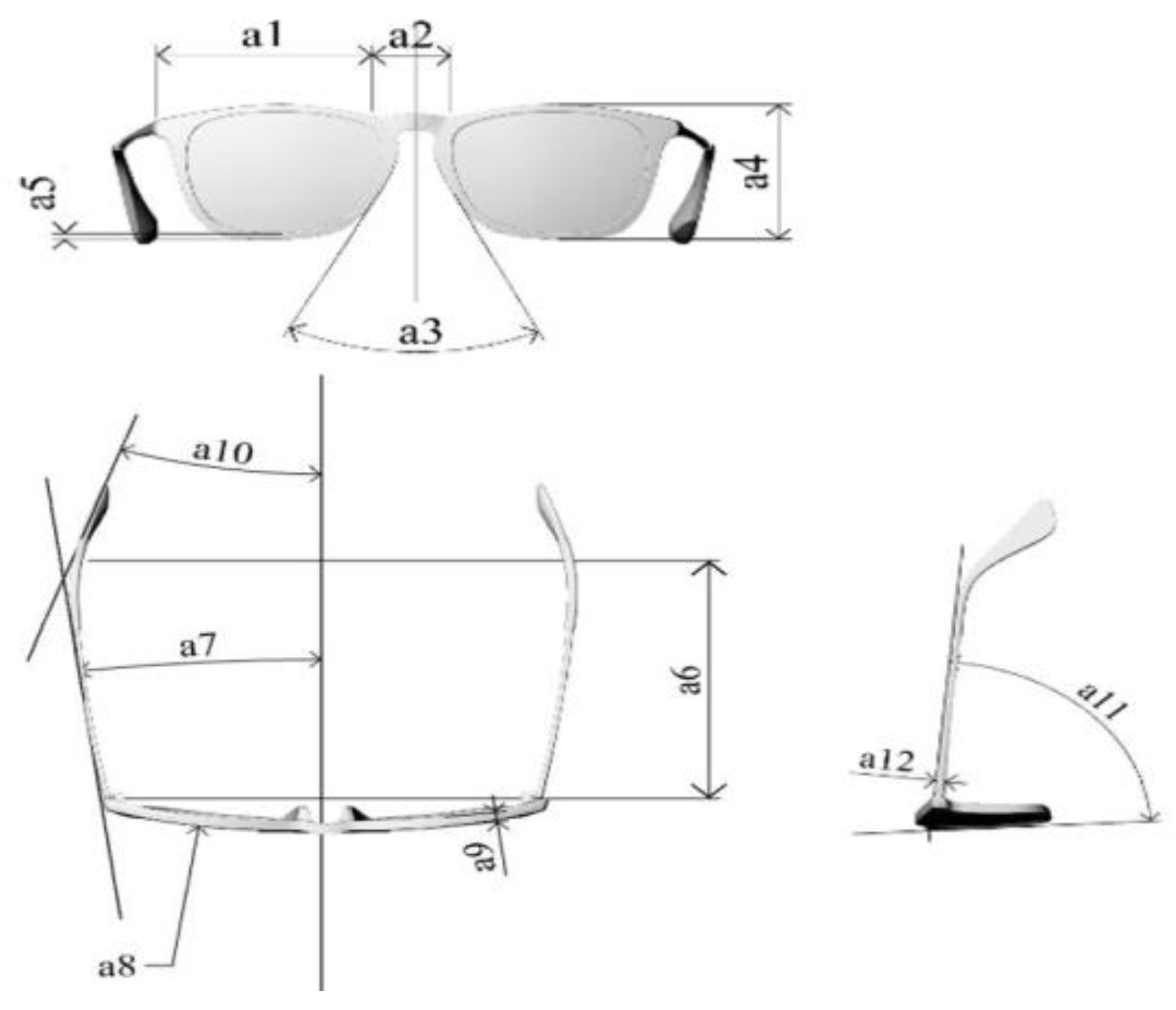
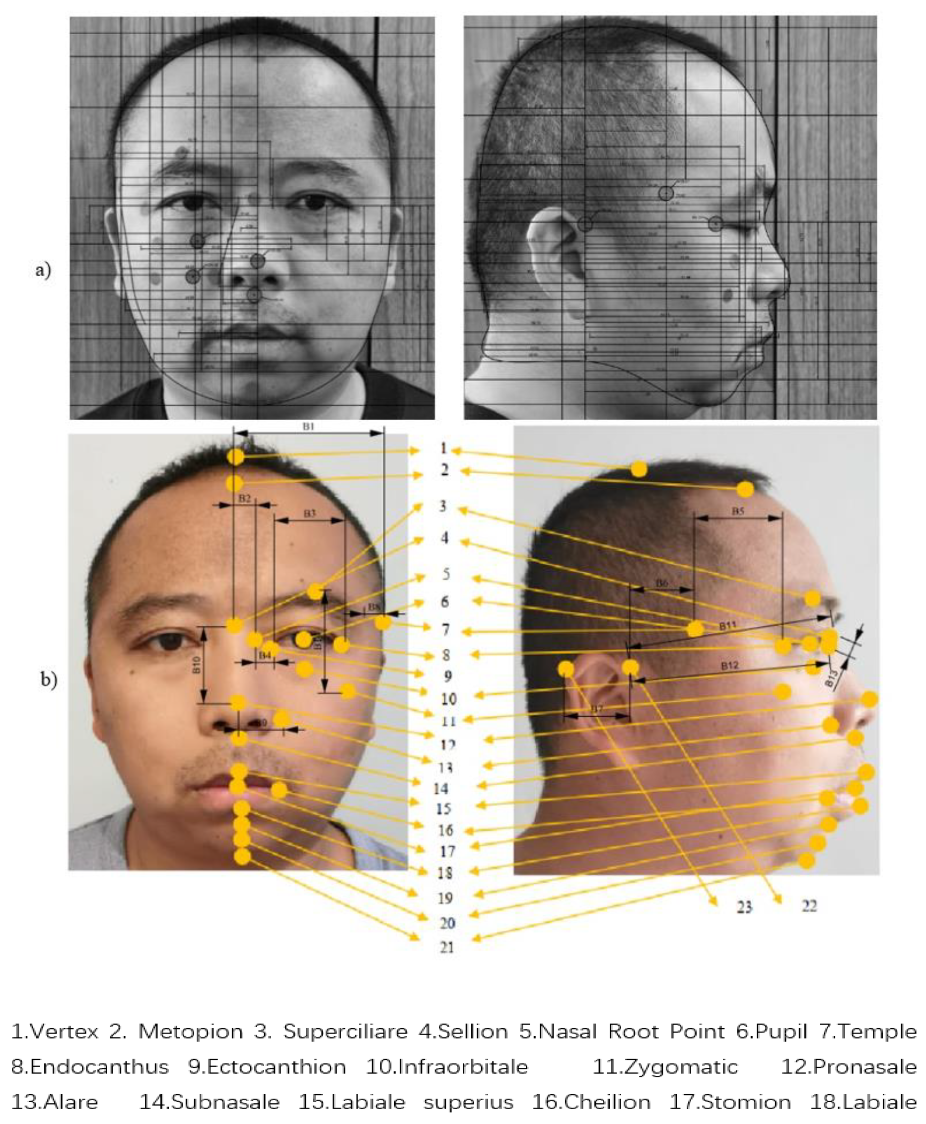
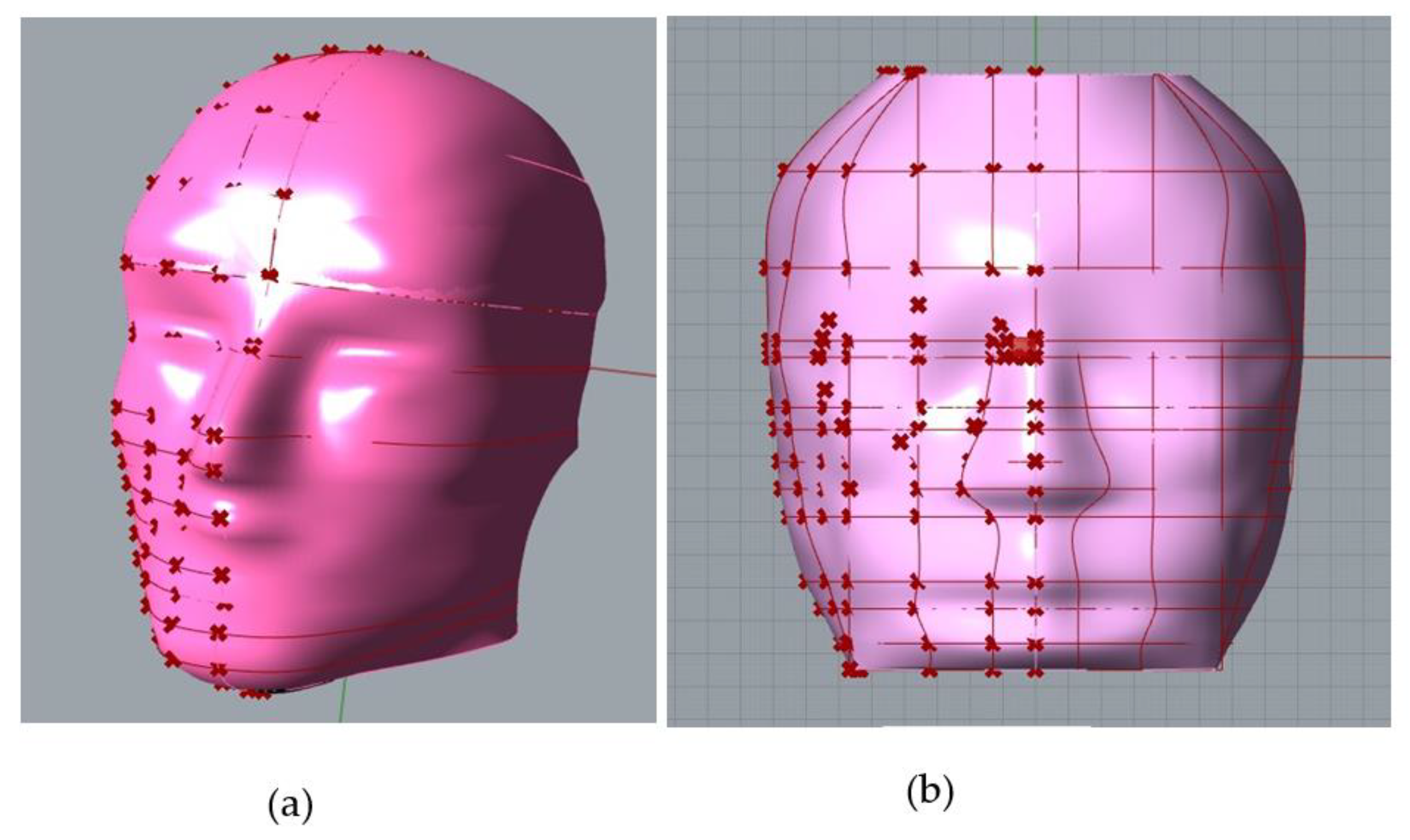
3.3. Determining the Head/Face Required Dimensions

To determine the required key feature points for the eyewear design (Figure 4), different types of eyewear products were analyzed and key feature points were correlated to head/face measurements as shown in Figure 5a,b. The selection of these key points is based on the feature points suggested in the literature [43,55], and they were combined with points shown in Figure 4 and Table 1 to determine the relevant feature points for the eyewear design.
The relationship between eyewear size and the head feature points was stablished through a simple correlation to facilitate the control of parameters using Grasshopper. The following eyewear frame considerations were made:
(1). If the frame is too narrow and the distance between the legs is too close, the lateral orbital tissues will be compressed, causing symptoms such as head distention and headache. Therefore, eyewear frame size and head size should have the following relationship.
a 1 + 0.5 a 2 B 2 + B 3 + B 4
The angle of template should be calculated according to the Formula (2).
a 7 tan 1 B 2 + B 4 + B 3 B 1 B 5 + B 6
Additionally, to ensure comfortable wearing, the a8 radian of the eyewear frame is determined by the curve of the face, where a8 should be at a certain distance from the feature points 3, 4, 6, 7, 8, 9, 22.
(2). When the length from the hinge of the frame to the point above the ear is too long, and the bending contour of the frame does not match the outline of the ear base, it is difficult for the frame to remain stable and in place. Therefore, the length of the temples can be calculated according to:
a 6 B 5 + B 6
and the back leg angle of eyewear can be calculated using:
a 10 tan 1 B 8 B 9
(3). The height and thickness of the front end of the nasal bone play an important determinant for the stability of the nose pads of the glasses. The shape of the nose pads varies greatly from one individual to another, so the supporting effect of the glasses varies greatly. This was considered through:
a 3 tan 1 B 9 B 2 B 10
a 2 2 B 2
The stability of the glasses also requires a stable triangular relationship between the frame and the bridge of the nose, and this was considered through:
a 11 cos 1 B 11 2 + B 13 2 B 12 2 2 B 11 B 13
Optical centre and interpupillary distance of the lens is also an important functional consideration. The position of the lens needs to be determined according to the position of the pupil, and the inner and outer corners of the orbit. The eyelid, and the cheekbones are used to determine the size of the lens.
a 1 B 3
a 4 B 14
In Formulas (1)–(9), points a1a11 correspond to eyewear size parameters as shown in detail in Table 1 and Figure 4. Dimensions are represented by B1B14 points as shown in Figure 5b. The feature points with serial numbers 1–23 are represented in the coordinate system as ( x n , y n , z n ) , n = 1 , 2 23 .
Then
B 1 = | x 7 x 4 | ,   B 2 = | x 5 x 4 | ,   B 3 = | x 8 x 9 | ,   B 4 = | x 5 x 9 | ,   B 5 = | y 7 y 8 | ,   B 6 = | y 7 y 22 | ,   B 7 = | y 22 y 23 | ,   B 8 = | x 22 x 23 | ,   B 9 = | x 13 x 12 | ,   B 10 = | z 4 z 12 | ,   B 11 = | ( z 4 z 22 ) 2 + ( y 4 y 22 ) 2 | ; B 12 = | ( z 22 z 10 ) 2 + ( y 22 y 10 ) 2 | ,   B 13 = | ( z 4 z 5 ) 2 + ( y 4 y 5 ) 2 | ,   B 14 = | z 3 z 11 | .
To correlate the aforementioned points to human head measurements orthogonal pictures were used. Before taking the pictures, small location circles were attached to the face. These markers (Figure 5a) were used to calibrate the feature points. Additionally, auxiliary calibration points were positioned at the intersection of horizontal and vertical lines. Pictures were taken with the head parallel to the Frankfurt plane, with the body upright and the shoulders flat. Auxiliary calibration points were used to ensure head posture was kept in position in comparison to the horizontal and vertical axes. Pictures were post-processed (see Figure 5a), to sharpen the edges of the image. The edge contour of the head was then extracted, and the photos were gridded according to the calibrated feature points. Then the coordinate origin was determined, and the plane coordinate system was established. According to the plane coordinate system, the dimension of each feature point in the photo was obtained. The outline of each marker was traced, and its real dimension was obtained using:
H 0 = H p × i = 1 n D i n D 0
where H0 is the real size measurement, D0 is the measurement of the small circles, and n is the number of small circles measured and the picture. The eyewear feature points and their correlation to the human head are given in Table 1.
The correlated points obtained from the analyzed eyewear and the relevant human head anatomy (Figure 5b) were used to accurately create a parametric 3D model of a human head. Considering the human head morphology, several planes were used to divide the 3D model (see Figure 6) in order to transform it into a 3D coordinate system that was used as a foundation for the parametric modelling. This coordinate system was composed of 18 planes at points 2~7, 10~15, 17~20 and 22; and another one at the midpoint between 3 and 4. Due to the high level of detail around the eye, this area was divided in more detailed sections to facilitate the accuracy of the measurements. The 3D coordinate system has a vertical plane passing through point 4, a horizontal plane passing through point 6 and another plane passing through point 22. The intersection of these three planes is calculated as the coordinate origin O.
The curves created by the intersection of these 18 planes and the 3D head model are divided into three categories according to their shape as shown in Figure 7. The shape of the curve on the plane above point 4 is type A, the shape of the curve on the plane between points 4~13 is type B, and the curve on the plane between 15~18 is type C.

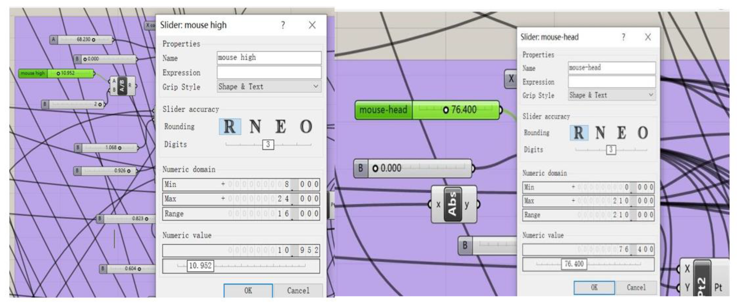
3.4. Algorithm Development, Parametric Design, and Good Fit Test

The parametrized head model shown in Figure 8 was developed using the dimensions obtained from the 3D scanned data. The 3D scanning model was segmented according to the method shown in Figure 6, and the contour lines were then extracted (see Figure 8a). Feature points (Figure 8b) correspond to those described previously in Figure 7. The original curve was fitted using a cubic B-spline curve (see Figure 8b), and surfaces were then generated. When establishing the parameterized head model program, a range of key dimensions corresponding to the size of head and biectocanthus were considered using a similar method presented by Lee et al. [37].
Figure 9 shows the algorithm and parametric design in the 3D modelling software Rhinoceros(McNeel Asia, Seattle, WA 98103, USA) with the visual programming tool Grasshopper. These tools were used to reference native Rhinoceros geometries and other inputs such as images.
To create the customized 3D head model, two orthogonal photos were taken as shown in Figure 5a. These photos were used to create a 3D model based on frontal face features and nose profile. According to the relationship between the feature points and the head size, the eyewear model was obtained by using Grasshopper directly on the parametric model of the user’s head.
This parametric-based design framework was then used to adjust eyewear size and appearance in relation to the subject’s head anatomy. Then an iterative design process using Rhino and Grasshopper was used to do adjustments for comfort and good fit. The parametric eyewear was designed to fit users’ head size by correlating the dimensions described in Table 1 and the parametric 3D head model. Parametric eyewear models were further detailed in Rhino 3D for 3D printing. For eyewear fitting evaluation, the entire customization process was followed for 10 different users, and the resulting eyewear models were manufactured in ABS using an FDM 3D printer. Comfort was assessed in terms of good fit and compared to the current products used.

4. Results

The following results are divided into sections, including the preliminary evaluation of three scanning methods, the implementation of the parametric design framework, and eyewear fit evaluations.

4.1. 3D Full Head/Face Scanning and Parametric Head Model

Three scanning methods were evaluated to assess their suitability as a 3D capturing method for personalized and customized product design. The main aspects evaluated were mobility, availability, and data accuracy.

4.1.1. Photogrammetry

Photogrammetry presented quality and consistency issues. The main drawbacks this technology poses are its reliance on the steadiness of the operator, the space limitations for its operation, and the zenithal image capturing. Figure 10 shows the 3D model of the human head where the lack of cranial images leads to a heavily distorted head model that has little detail and use for customized product development. But recent drone-based and automated image capturing systems could help improve these results to allow access to a more reliable and low-cost 3D capturing method.

4.1.2. Somatosensory Camera Scanning

This 3D scanning method presented better results in comparison to photogrammetry. However, the continuous adjustment of the scanning distance to acquire usable 3D data requires practice and is time-consuming. Moreover, complete head scans cannot be obtained during one single step; the obtained scanned patches require a special program (i.e., Artec studio) to stitch the different sections. In general, this scanning method showed little accuracy, particularly close to the boundary of the object scanned (i.e, farthest region). Point clouds tend to be formed in the surrounding area of the head, resulting in redundant scanning data. Consequently, additional work was required to remove useless point clouds using the 3D scanning software. The practical experiment showed that 3D scanned data obtained through this technology did not retain enough facial features, making it not suitable for the product development in this study. (See Figure 11).

4.1.3. Laser Scanning

The laser-based scanning provided better results in terms of resolution, as shown in Figure 12. However, small movements such as blinking eyes can still cause some minor distortion in the final 3D model. Additionally, the scanning efficiency was influenced by different skin colour and type of skin (e.g., oily skin). One of the main drawbacks this technology presents is its high cost, the large amount of scanning data points, and the need of a specialized software for post-processing.

4.1.4. Scanning Comparison

The three scanning methods presented different advantages, as well as some drawbacks. Although the cost of photogrammetry is very low in comparison with the other methods, it is more time consuming and requires many pictures to be taken in a studio-controlled environment. Additionally, photogrammetry creates 3D models with low scanning accuracy. On the other hand, the scanning process using a somatosensory camera is easy to set up and low cost; however, the actual scanning process and operation is relatively complex, and the accuracy is not as high as the laser scanning method. Finally, the laser scanning method produced the most accurate model, but at a much higher cost than the other two methods used in this study. Furthermore, all the scanning methods evaluated in this work may not be widely available for ordinary end users. Therefore, this preliminary evaluation showed that these methods are not yet suitable and widely available for the intended eyewear and commercial application. Consequently, a new parametric method to create accurate 3D head/face models for eyewear design based on photography is proposed.

4.2. Algorithm Development, Parametric Design, and Good Fit Test

Parametric technology is a very effective method for mass customization, design, and product development as it allows for quick design iterations and gives designers and customers to opportunity to explore several design alternatives in a short timeframe.
Figure 13a,b shows the initial parametric 3D head model obtained from the extracted curves from scanned data in comparison with the parametric head model obtained from customer pictures. The user’s 3D model was created by substituting the measured values of each feature point into the parametric program in Grasshopper.
Parameter setting (Figure 14) allowed for a more flexible design process, where many design iterations could be explored in a real-time situation. For example, the ideal users’ frame needs to meet comfort and good fit requirements that could easily be adjusted using a parametric system. On the other hand, appearance requirements could also be explored through some quick real-time visualizations to offer the customer a preliminary view of the product.
According to the relationship established between the feature points and human head size, a corresponding eyewear model was designed using Grasshopper directly from the parametric model of the user’s head. The parametric eyewear was designed to fit users’ head size through this correlation previously stablished. This parametric-based design framework allowed the size and appearance of the eyewear to be changed as the dimensions of the human head changed. Therefore, each designed eyewear is parametrically linked to the user’s head size as shown in Figure 15a. Additionally, more parameters were added to further change the appearance of eyewear, so that it fits the shape of the face, as shown in Figure 15b.
After completing the parametric design of the eyewear, detailed design work was done to further refine the product and to prepare it for manufacturing (Figure 16). The eyewear 3D model was then 3D-printed to produce an early prototype for evaluation purposes as shown in Figure 17.
As shown in Figure 17a,b, the eyewear frame was consistent with the subject’s face shape and size. The eyewear temples were consistent with the participant’s head anatomy. The eyewear temple tips were tightly shaped around the back of the ear, describing a good fit. After 8 h of prolonged use and simulation of dynamic activities such as jumping and running, the frame remained in place, showing that the size and shape of eyewear was in good agreement with the face’s contact surface. In general, the users’ feedback was positive, stating that the eyewear frame was perfectly integrated to their face anatomy and was also comfortable to wear.

5. Conclusions

The experimental evaluation on three different scanning methods showed that laser-based technology accuracy is still higher and easier to set up and use. However, due to the higher cost of this technology, its use may be limited to projects that require a reduced number of scans with high resolution, making data collection by ordinary users less accessible. Although the somatosensory camera-based technology is more accessible, with a reasonable data accuracy, it requires further post-processing work and is harder to use. Finally, the use of 3D photo reconstruction software is time consuming and requires a specific setup and a large amount of data to be transferred, making the accuracy setup-dependent, hence the need of a new method to capture user head data. The method presented in this work delivered a low-cost alternative for the quick and flexible capture of concise data appropriate for mass-customized eyewear design. The data sets captured, and the flexibility of the tools used, allowed the creation of more complex designs. However, further work is needed to produce design files that require less post-processing. Automated post-processing algorithm blocks, or even the use of machine learning, could be further integrated.
The project produced a usable parametric-based design framework for eyewear design; however, some aspects of its use require specific knowledge from the designer perspective in order to create a seamless MC experience between designer and customer. Other aspects of this project could be further explored to have a larger impact on mass customization and personalized design. For example, the end-user inclusion in the design process needs to be improved, and its impact on the proposed framework and on the design process considered, so it is possible to provide a more inclusive design experience. Despite parametric parameters being pre-set by the designer, it is up to the customer/end-user to make the final decision on the details that give the product a unique character. As none of the eyewear may be the same, they could be described as one-off products, created with the help of software and computer iterations. On the other hand, the variations of similar eyewear forms, the limited production runs using 3D printing, and the involvement of the user in the design process may create a stronger relationship between the product and consumer. These factors along with the user’s perception of a crafted creation are of interest as new emerging technologies such as AI (artificial intelligence) and IoT (internet of things) continue to further blur the boundaries between art, craft, and design.
In this work, three main key elements were found to have a strong influence on the development of the parametric-based design framework for MC eyewear:
  • Human centred-based approach: Within a complex MC system, the uncovering of user and other stakeholders needs (e.g., designer) poses one of the biggest challenges. Therefore, human-centred design methods may bring a better understanding of the user needs in order to ease the implementation of MC strategies.
  • Technology appropriateness: In the process of personalised and mass customisation design of wearable products, convenient and accurate acquisition of users’ body data has become a key factor for customisation design. The quality of this data relies mostly on technology appropriateness, setup, and user expertise. The user experience of the data acquisition in commercial setups is a factor that requires further research.
  • Real-time feedback: In the process of personalisation and mass customisation of eyewear, parametric design is an effective and flexible tool to quickly realise product design iterations and explore the meeting of some of the needs of different users by adjusting design parameters and getting users’ real-time feedback.
With the maturity of 3D imaging technology and 3D printing technology, the remote mode for design and production of personalized, customized, and rapidly manufactured products is gradually entering people’s day-to-day lives. For the personalized production of eyewear, some of the following factors can be addressed to facilitate this transition:
  • Clear communication strategy with consumers/end-users: this could facilitate the identification of needs to be met and clearly define the project scope.
  • Inclusive co-design process: A clear co-design strategy with well-defined roles and requirements could ease the decision-making process that is involved in the personalisation or customisation process.
  • Technical and aesthetic requirements: personalised and customised products, in particular eyewear, are expected to meet the basic personal needs of consumers in terms of comfort, functionality, and aesthetics. These can be fully defined during the inclusive co-design process.
  • User experience and human-centred focus: the development of a user-friendly Software/Visual Programming tool that enables the above tasks should be at the core of this type of work. A human-centred approach for the development of these tools is necessary for a seamless co-design experience.
  • Agile manufacturing: having the ability to adapt and to respond quickly to rapidly changing markets driven by customer-based needs is important for MC strategies. For eyewear products, current 3D printing technologies and available materials have reached a level of maturity that provides a good alternative.
  • Integration of new technologies: having a flexible framework that allows the integration of new technologies or strategies could increase the potential of this type of MC framework. For example, machine learning and artificial intelligence could be used to collect and analyse users’ data to pre-identify patterns in preferences to help determine the design requirements.

Author Contributions

Conceptualisation, X.B., O.H. and E.U.; methodology, X.B., O.H., and E.U.; software, X.B. and J.A.; validation, J.A. and J.E.C.; formal analysis, X.B., J.A., and J.E.C.; resources, O.H. and E.U.; data curation, X.B.; writing—original draft preparation, X.B., O.H., and E.U.; writing—review and editing, X.B., O.H., E.U., J.A., and J.E.C.; visualization, X.B., O.H., and E.U.; supervision, O.H. and E.U. All authors have read and agreed to the published version of the manuscript.

Funding

Please add: This research was funded by THE NATIONAL SOCIAL SCIENCE FUND OF CHINA, grant number 18BG132.

Institutional Review Board Statement

Eth-ical review and approval were waived for this study, due to REASON (The main object of this study is wearable products).

Informed Consent Statement

Written informed consent has been obtained from the patient(s) to publish this paper.

Acknowledgments

We thank the anonymous reviewers for their insightful suggestions and recommendations, which led to the improvements of the presentation and content of the paper.

Conflicts of Interest

The authors declare no conflict of interest.

References

  1. Simpson, T.W. Product platform design and customization: Status and promise. Artif. Intell. Eng. Des. Anal. Manuf. 2004, 18, 3–20. [Google Scholar] [CrossRef] [Green Version]
  2. Ali, K.; Smadi, H.; Salhieh, S.M. Two-phase methodology for customized product design and manufacturing. J. Manuf. Technol. Manag. 2012, 23, 370–401. [Google Scholar]
  3. Tseng, M.M.; Jiao, J. Mass Customization. In Handbook of Industrial Engineering, 3rd ed.; Salvendy, G., Ed.; Wiley: Hoboken, NJ, USA, 2001; pp. 684–709. [Google Scholar]
  4. Herstatt, C.; Verworn, B. The ‘fuzzy front end’ of innovation. In Bringing Technology and Innovation into the Boardroom; Palgrave Macmillan: London, UK, 2004; pp. 347–372. [Google Scholar]
  5. Oliveira, M.G.; Phaal, R.; Probert, D.; Cunha, V.P.; Rozenfeld, H. A starting point for addressing product innovativeness in the fuzzy front-end. Int. J. Technol. Intell. Plan. 2011, 7, 309–326. [Google Scholar] [CrossRef]
  6. Dean, L.; Unver, E.; Campbell, I.; De Beer, D. Making it real: Virtual tools in 3D creative practice. In Proceedings of the Making: An International Conference on Materiality and Knowledge, Book of Abstracts, NordFo, Nordic Research Network, Notodden, Norway, 24–27 September 2012; p. 76. [Google Scholar]
  7. O’Sullivan, M.; Sheahan, C. Using Innovation Games to Assess Mass Customisation Potential from the Fuzzy Front-End. In Proceedings of the ECIE 2019 14th European Conference on Innovation and Entrepreneurship, Kalamata, Greece, 19–20 September 2019; p. 2. [Google Scholar]
  8. Jitpaiboon, T.; Dobrzykowski, D.D.; Ragu-Nathan, T.S.; Vonderembse, M.A. Unpacking IT use and integration for mass customisation: A service-dominant logic view. Int. J. Prod. Res. 2013, 51, 2527–2547. [Google Scholar] [CrossRef]
  9. Kristal, M.M.; Huang, R.; Schroeder, R.G. The effect of quality management on mass customization capability. Int. J. Oper. Prod. Manag. 2010, 30, 900–920. [Google Scholar] [CrossRef]
  10. Gilmore, J.H.; Pine, B.J. The four faces of mass customization. Harv. Bus. Rev. 1997, 75, 91–102. [Google Scholar]
  11. Montalto, A.; Graziosi, S.; Bordegoni, M. An approach to design reconfigurable manufacturing tools to manage product variability: The mass customisation of eyewear. J. Intell. Manuf. 2018, 31, 1–16. [Google Scholar] [CrossRef] [Green Version]
  12. Da Silveira, G.; Borenstein, D.; Fogliatto, F.S. Mass customization: Literature review and research directions. Int. J. Prod. Econ. 2001, 72, 1–13. [Google Scholar] [CrossRef]
  13. Spira, J.S. Mass customization through training at Lutron Electronics. Plan. Rev. 1993, 21, 23–24. [Google Scholar] [CrossRef]
  14. Berger, C.; Moslein, K.; Piller, F.; Reichwald, R. Cooperation between manufacturers, retailers, and customers for user co-design: Learning from exploratory research. Eur. Manag. Rev. 2005, 1, 70–87. [Google Scholar] [CrossRef]
  15. Pedersen, S.N.; Christensen, M.E.; Howard, T.J. Robust Design Requirements Specification: A Quantitative Method for Requirements Development Using Quality Loss Functions. J. Eng. Des. 2016, 27, 544–567. [Google Scholar] [CrossRef]
  16. Desmet, P.; Pohlmeyer, A. Positive Design: An Introduction to Design for Subjective Well-Being. Int. J. Des. 2013, 7, 5–19. [Google Scholar]
  17. Zöller, S.G.; Wartzack, S. Considering Users’ Emotions in Product Development Processes and the Need to Design for Attitudes. Emot. Eng. 2017, 5, 69–97. [Google Scholar]
  18. Chong, Y.T.; Chen, C.H. Customer needs as moving targets of product development: A review. Int. J. Adv. Manuf. Technol. 2010, 48, 395–406. [Google Scholar] [CrossRef]
  19. Ulrich, K.T. The role of product architecture in the manufacturing firm. Res. Policy 1995, 24, 419–440. [Google Scholar] [CrossRef] [Green Version]
  20. Dove, R. The 21s Century Manufacturing Enterprise Strategy; AD-A257176; Iacocca Institute, Lehigh University Press: Bethlehem, PA, USA, 1991. [Google Scholar]
  21. Rinaldi, M.; Caterino, M.; Manco, P.; Fera, M.; Macchiaroli, R. The impact of Additive Manufacturing on Supply Chain design: A simulation study. Procedia Comput. Sci. 2021, 180, 446–455. [Google Scholar] [CrossRef]
  22. Jagdev, H.S.; Browne, J. The extended enterprise a context for manufacturing. Prod. Plan. Control 1998, 9, 216–229. [Google Scholar] [CrossRef]
  23. Storch, R.L.; Lim, S. Improving flow to achieve lean manufacturing in shipbuilding. Prod. Plan. Control 1999, 10, 127–137. [Google Scholar] [CrossRef]
  24. Warnecke, H.J.; Hüser, M. Lean production. Int. J. Prod. Econ. 1995, 41, 37–43. [Google Scholar] [CrossRef]
  25. Deradjat, D.; Minshall, T. Implementation of rapid manufacturing for mass customisation. J. Manuf. Technol. Manag. 2017, 28, 95–121. [Google Scholar] [CrossRef] [Green Version]
  26. Mehrabi, M.G.; Ulsoy, A.G.; Koren, Y. Reconfigurable manufacturing systems: Key to future manufacturing. J. Intell. Manuf. 2000, 11, 403–419. [Google Scholar] [CrossRef]
  27. Kaiser, C.; Fischer, T.V.; Schmeltzpfenning, T.; Stöhr, M.; Artschwager, A. Case study: Mass customisation of individualized orthotics–the fashion-able virtual development and production framework. Procedia CIRP 2014, 21, 105–110. [Google Scholar] [CrossRef] [Green Version]
  28. Hirsch, B.E.; Thoben, K.D.; Hoheisel, J. Requirements upon human competencies in globally distributed manufacturing. Comput. Ind. 1998, 36, 49–54. [Google Scholar] [CrossRef]
  29. Kouchi, M. Secular changes in the Japanese head form viewed from somatometric data. Anthropol. Sci. 2004, 112, 41–52. [Google Scholar] [CrossRef] [Green Version]
  30. Ziqing, Z.; Douglas, L.; Stacey, B.; Raymond, R.; Ronald, S. Facial Anthropometric Differences among Gender, Ethnicity, and Age Groups. Ann. Occup. Hyg. 2010, 54, 391–402. [Google Scholar]
  31. Lee, H.J.; Park, S.J. Comparison of korean and japanese head and face anthropometric characteristics. Hum. Biol. 2008, 80, 313–330. [Google Scholar] [CrossRef]
  32. Ball, R.; Shu, C.; Xi, P.; Rioux, M.; Luximon, Y.; Molenbroek, J. A comparison between Chinese and Caucasian head shapes. Appl. Ergon. 2010, 41, 832–839. [Google Scholar] [CrossRef]
  33. Hanson, L.; Sperling, L.; Gard, G.; Ipsen, S.; Vergara, C.O. Swedish anthropometrics for product and workplace design. Appl. Ergon. 2009, 40, 797–806. [Google Scholar] [CrossRef]
  34. Purkait, R.; Singh, P. Anthropometry of the normal human auricle: A study of adult indian men. Aesthetic Plast. Surg. 2017, 31, 372–379. [Google Scholar] [CrossRef]
  35. Fan, H.; Yu, S.; Chu, J.; Wang, M.; Wang, N. Anthropometric characteristics and product categorization of chinese auricles for ergonomic design. Int. J. Ind. Ergon. 2019, 69, 118–141. [Google Scholar] [CrossRef]
  36. Zhu, Z.; Ji, X.; Gao, Z.; Hu, G. A morphometric study of auricular concha in the population of young chinese adults. Int. J. Morphol. 2017, 35, 1451–1458. [Google Scholar] [CrossRef] [Green Version]
  37. Lee, W.; Lee, B.; Yang, X.; Jung, H.; Bok, I.; Kim, C.; You, H. A 3D anthropometric sizing analysis system based on North American CAESAR 3D scan data for design of head wearable products. Comput. Ind. Eng. 2018, 117, 121–130. [Google Scholar] [CrossRef]
  38. Perret-Ellena, T.; Skals, S.L.; Subic, A.; Mustafa, H.; Pang, T.Y. 3D Anthropometric investigation of Head and Face characteristics of Australian Cyclists. Procedia Eng. 2015, 112, 98–103. [Google Scholar] [CrossRef] [Green Version]
  39. Montalto, A.; Graziosi, S.; Bordegoni, M.; Landro, L.D. Combining aesthetics and engineering specifications for fashion-driven product design: A case study on spectacle frames. Comput. Ind. 2018, 95, 102–112. [Google Scholar] [CrossRef]
  40. Brodie, F.L.; Nattagh, K.; Shah, V.; Swarnakar, V.; Lin, S.; Kelil, T.; de Alba Campomanes, A.G. Computed tomography–based 3D modeling to provide custom 3D-printed glasses for children with craniofacial abnormalities. J. Am. Assoc. Pediatr. Ophthalmol. Strabismus 2019, 23, 165–167. [Google Scholar] [CrossRef] [PubMed]
  41. Zhuang, Z.; Shu, C.; Xi, P.; Bergman, M.; Joseph, M. Head-and-face shape variations of U.S. civilian workers. Appl. Ergon. 2013, 44, 775–784. [Google Scholar] [CrossRef] [PubMed] [Green Version]
  42. Ball, R.M. SizeChina: A 3D Anthropometric Survey of the Chinese Head. Ph.D. Thesis, The Hong Kong Polytechnic University, Hong Kong, China, 2011. [Google Scholar]
  43. Luximon, Y.; Ball, R.; Justice, L. The 3D Chinese head and face modeling. Comput. Aided Des. 2012, 44, 40–47. [Google Scholar] [CrossRef]
  44. Zheng, R.; Yu, W.; Fan, J. Development of a new chinese bra sizing system based on breast anthropometric measurements. Int. J. Ind. Ergon. 2007, 37, 697–705. [Google Scholar] [CrossRef]
  45. Ji, X.; Zhu, Z.; Gao, Z.; Bai, X.; Hu, G. Anthropometry and classification of auricular concha for the ergonomic design of earphones. Hum. Factors Ergon. Manuf. Serv. Ind. 2017, 28, 90–99. [Google Scholar] [CrossRef]
  46. Perret-Ellena, T.; Mustafa, H.; Subic, A.; Pang, T.Y. A design framework for the mass customisation of custom-fit bicycle helmet models. Int. J. Ind. Ergon. 2018, 64, 122–133. [Google Scholar] [CrossRef]
  47. Pang, T.Y.; Lo, T.S.T.; Ellena, T.; Mustafa, H.; Babalija, J.; Subic, A. Fit, stability and comfort assessment of custom-fitted bicycle helmet inner liner designs, based on 3d anthropometric data. Appl. Ergon. 2018, 68, 240–248. [Google Scholar] [CrossRef]
  48. Li, J.; Ye, J.; Wang, Y.; Bai, L.; Lu, G. Fitting 3d garment models onto individual human models. Comput. Graph. 2010, 34, 742–755. [Google Scholar] [CrossRef]
  49. Lu, L.G. Customizing 3d garments based on volumetric deformation. Comput. Ind. 2011, 62, 693–707. [Google Scholar]
  50. Liu, H.; Li, Z.; Zheng, L. Rapid preliminary helmet shell design based on three-dimensional anthropometric head data. J. Eng. Des. 2008, 19, 45–54. [Google Scholar] [CrossRef]
  51. Hsu, M.C.; Wang, C.; Herrema, A.J.; Schillinger, D.; Ghoshal, A.; Bazilevs, Y. An interactive geometry modeling and parametric design platform for isogeometric analysis. Comput. Math. Appl. 2015, 70, 1481–1500. [Google Scholar] [CrossRef]
  52. Chu, C.H.; Wang, I.J.; Wang, J.B.; Luh, Y.P. 3D parametric human face modeling for personalized product design: Eyeglasses frame design case. Adv. Eng. Inform. 2017, 32, 202–223. [Google Scholar] [CrossRef]
  53. Huang, S.H.; Yang, Y.I.; Chu, C.H. Human-centric design personalization of 3d glasses frame in markerless augmented reality. Adv. Eng. Inform. 2012, 26, 35–45. [Google Scholar] [CrossRef]
  54. Lu, W.; Petiot, J.F. Affective design of products using an audio-based protocol: Application to eyeglass frame. Int. J. Ind. Ergon. 2014, 44, 383–394. [Google Scholar] [CrossRef]
  55. Shintaku, H.; Yamaguchi, M.; Toru, S.; Kitagawa, M.; Hirokawa, K.; Yokota, T.; Uchihara, T. Three-dimensional surface models of autopsied human brains constructed from multiple photographs by photogrammetry. PLoS ONE 2019, 14, e0219619. [Google Scholar] [CrossRef] [Green Version]
Figure 1. Parametric modelling strategy.
Applsci 11 05382 g001
Figure 2. Photogrammetry image.
Applsci 11 05382 g002
Figure 3. Scanning tool.
Applsci 11 05382 g003
Figure 4. Dimensioning of eyewear.
Applsci 11 05382 g004
Figure 5. (a) Orthogonal photo; (b) Feature points for head measurement.
Applsci 11 05382 g005
Figure 6. Plane location according to feature points.
Applsci 11 05382 g006
Figure 7. Type of curve.
Applsci 11 05382 g007
Figure 8. (a) Curve extraction; (b) curve fitting.
Applsci 11 05382 g008
Figure 9. Algorithm developed in Grasshopper.
Applsci 11 05382 g009
Figure 10. The result of photo reconstruction.
Applsci 11 05382 g010
Figure 11. Somatosensory camera.
Applsci 11 05382 g011
Figure 12. Laser scan image.
Applsci 11 05382 g012
Figure 13. (a) Parametric standard head; (b) User’s parametric head modelling.
Applsci 11 05382 g013
Figure 14. Parameter setting.
Applsci 11 05382 g014
Figure 15. (a) Parametric Eyewear Design 1; (b) Parametric Eyewear Design 2.
Applsci 11 05382 g015
Figure 16. (a) Detail design of eyewear1;(b) Detail design of eyewear 2.
Applsci 11 05382 g016
Figure 17. (a) 3D printed prototype; (b) evaluation of comfort.
Applsci 11 05382 g017
Table 1. Eyewear feature point for dimensioning.
Eyewear Size Parameters (Figure 4)Size NameExplanation of SizeHead Feature Points Related to the Eyewear Size (Figure 5b)
a1Eye sizeIndicates the width of the lens6,8,9
a2Bridge widthConnection section of lens4,5,6
a3Nose angleDecide where to contact the eyewear and nose4,5,12,13,14
a4Lens heightHeight of glasses, determined by appearance3,5,8,10,11
a5Height of frameHeight of eyeglasses frame section, determined by appearance
a6The temple sizeDistance from eyewear frame to ear7,22
a7Angle of templeThe angle between the temple and the symmetrical plane of head7,22
a8Curvature of eyewear frameCurvature of the eyewear frame3,4,6,7,8,9,22
a9Thickness of frameThickness of eyewear frame section, determined by appearance
a10Back leg angle of eyewearBack leg angle of glasses22,23
a11Angle of eyewear frameAngle between frame and temple4,5,7,11
a12Thickness of templeThickness of temple
Publisher’s Note: MDPI stays neutral with regard to jurisdictional claims in published maps and institutional affiliations.

