Review

Advances in Piezoelectric Jet and Atomization Devices

1
School of Electrical Engineering, Nantong University, Nantong 226019, China
2
Institute of Intelligent Manufacturing and Information Technology, Jiangsu Shipping College, Nantong 226010, China
3
School of Materials Science and Engineering, Harbin Institute of Technology, Harbin 150001, China
4
Taizhou Polytechnical Institute, College of Mechanical and Electrical Technology, Taizhou 225300, China
*
Author to whom correspondence should be addressed.
Appl. Sci. 2021, 11(11), 5093; https://doi.org/10.3390/app11115093
Submission received: 7 April 2021 / Revised: 26 April 2021 / Accepted: 6 May 2021 / Published: 31 May 2021
(This article belongs to the Collection Progress in Liquid Atomization and Spray Systems)

Abstract

:
In recent years, the piezoelectric jet and atomization devices have exhibited tremendous advantages including their simple construction, and the fact that they are discreet and portable as well as low cost. They have been widely used in cell printing, spray cooling, drug delivery, and other industry fields. First, in this paper, two different concepts of jet and atomization are defined, respectively. Secondly, based on these two concepts, the piezoelectric jet and atomization devices can be divided into two different categories: piezoelectric micro jet device and piezoelectric atomization device. According to the organizational structure, piezoelectric micro jet devices can be classified into four different models: bend mode, push mode, squeeze mode, and shear mode. In addition, their development history and structural characteristics are summarized, respectively. According to the location of applied energy, there are two kinds of piezoelectric atomization devices, i.e., the static mesh atomization device and the vibration mesh atomization device, and both their advantages and drawbacks are discussed. The research achievements are summarized in three aspects of cell printing, spray cooling, and drug delivery. Finally, the future development trends of piezoelectric jet and atomization devices are prospected and forecasted.

1. Introduction

Atomization is defined as a process of transforming continuous liquid or solid–liquid mixtures into discrete droplets or solid particles by various approaches. The research on atomization can be traced back to Leonardo da Vinci in the 16th century [1]. The introduction of atomization can dramatically increase the specific surface area of the fluid, and significantly improve the efficiency of fluid utilization. It is widely used in the fields of air humidification [2], agricultural irrigation [3], spray combustion [4], and many other industries. Since the piezoelectric effect was discovered in 1880, many scholars began to devote investigating to the piezoelectric driving. It was found that the piezoelectric actuator belongs to a kind of inverse piezoelectric effect based on piezoelectric ceramic material, which can produce rotation or linear motion by controlling its mechanical deformation. Uchino et al. [5,6] summarized the construction, working principle, structural material, and energy recovery of piezoelectric actuators, which laid the foundation for the research on piezoelectric actuators. Due to the advantages of piezoelectric actuators, their research results have been widely applied in ultrasonic motor [7,8,9], piezoelectric pump [10,11,12], and piezoelectric atomization [13,14,15].
The procedure of piezoelectric jet and atomization is the most important branch of the piezoelectric drive during such processing, where the liquid is dispersed into tiny droplets by piezoelectric drive technology, and its corresponding devices are the piezoelectric jet and atomization devices. The piezoelectric jet and atomization devices have numerous advantages such as being easy to carry, and having a high energy utilization rate, and low manufacturing cost, which have drawn public attention in various fields. In recent decades, such piezoelectric jet and atomization devices have been extensively promoted and applied in inhalation drug delivery [16], metal printing [17], biomedical [18], and other aspects. The piezoelectric micro jet device and the piezoelectric atomization device have been proposed for many years, but due to the limitations of the technical level, there is no literature to distinguish such concepts of jet and atomization, especially for what collectively refers to the two concepts of jet and atomization as the process of dispersing liquid into tiny droplets. In order to better understand and distinguish clearly, we give two different definitions for jet and atomization, respectively. When the liquid is occupied with an absolute higher proportion of ejected material than the gas, it is regard as jet; otherwise, it will be defined as atomization.
In this paper, the work on the evolution and progress trend of the constructions of piezoelectric micro jet and atomization devices in the past three decades are reviewed and summarized. The development history of the structure of the piezoelectric micro jet and atomization device is also reviewed. The functions and applications of piezoelectric micro jet and atomization devices are classified and thoroughly analyzed, and their future development is prospected.

2. Advances in Piezoelectric Micro Jet Devices
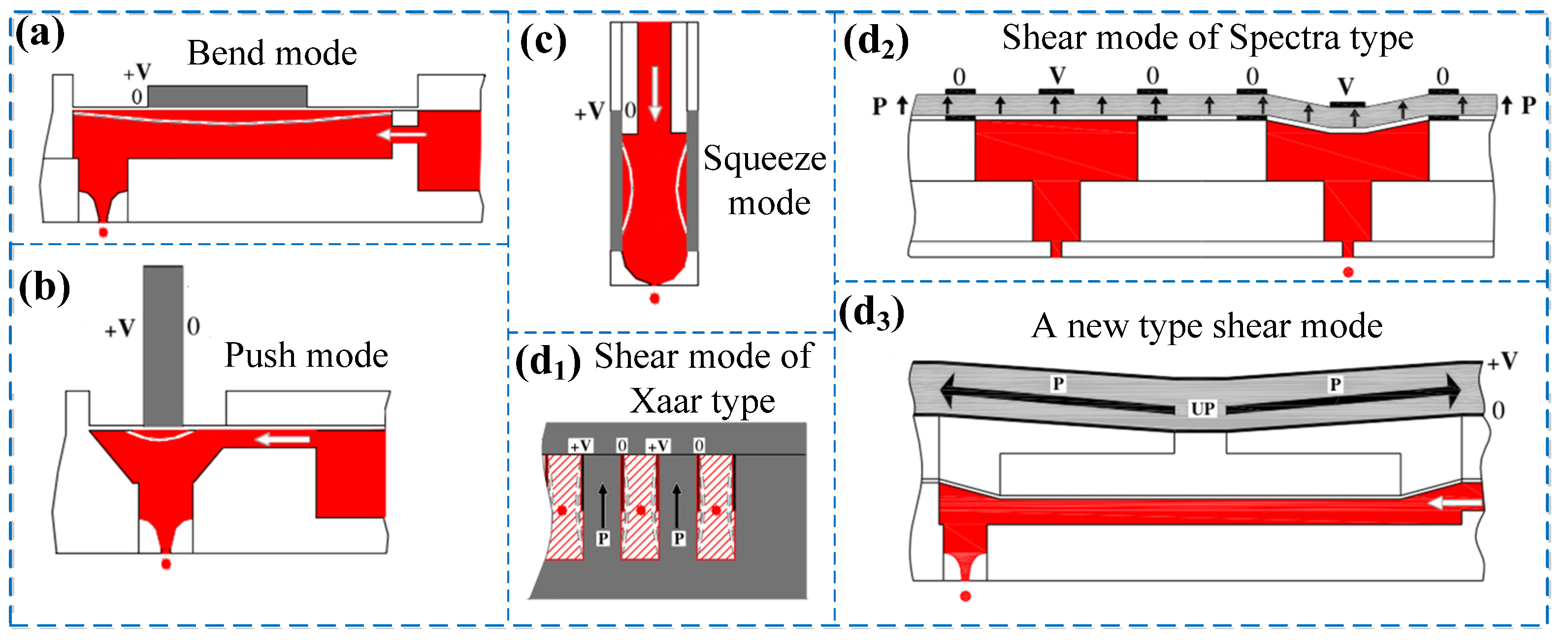
The working principles of the piezoelectric micro jet device can be divided into three stages: (i) the driving signal is employed as the piezoelectric vibrator; (ii) the inverse piezoelectric effect of piezoelectric ceramics is used to make the piezoelectric vibrator deform; and (iii) the pressure wave is subsequently generated and acted on the liquid to extrude the liquid from the micropore. The earliest application of piezoelectric micro jet technology is the piezoelectric inkjet printer, in which the conversion of electrical energy to mechanical energy is achieved under the action of the AC signal, leading to the piezoelectric device deformation, extruding the ink to spray it on the paper (or other media) and finally the printing of text and figure [19]. Figure 1 shows the structure diagram of the piezoelectric micro jet device [20]. According to the deformation mode of the piezoelectric vibrator, the piezoelectric micro jet devices can be roughly divided into four types, including bend mode [21], push mode [22], squeeze mode [23], and shear mode [20].

2.1. Bend Mode

In 2008, Fan et al. [25] proposed a type of piezoelectric inkjet nozzle and fabricated the piezoelectric ceramic into the shape of a buzzer. The surrounding of the piezoelectric ceramic was fixed, and the middle part was deformed to drive the formation of droplets. In this research, a high-speed camera (CCD) was employed to record the formation and separation process of the droplets. In a previous study, Yang et al. [26] carried out numerical simulation on the droplet injection process of a representative piezoelectric film nozzle, and the related findings revealed that the injection characteristics were strongly affected by many factors including the nozzle outlet diameter, injection time interval, and surface tension as well as fluid viscosity. Since then, with the development of MEMS technology, some scholars have begun to use MEMS technology to design piezoelectric micro jet devices. In 2010, Yoo et al. [27] designed a piezoelectric nozzle using MEMS technology, and found that the nozzle structure, driving voltage, ink viscosity, and meniscus vibration mode all affected the spray performance of the nozzle. In 2014, Kim et al. [28] fabricated a piezoelectricity driven inkjet printhead on silicon wafer by MEMS technology, and carried out a numerical simulation on this course. It was found that the Helmholtz mode was the main resonance mode to influence the flow oscillation at the nozzle. As one of the core components of the piezoelectric nozzle, the piezoelectric vibration plate directly affects the jet performance of the print head. In 2018, the amplitude of the piezoelectric vibration plate was enhanced by releasing the long side of lead zirconate titanate film, and thereby a so-called spring structure was conducted, demonstrating that such a structure can significantly increase the amplitude and average deformation rate of a piezoelectric vibration plate in air throughout the experimental progress [29].
All of the above-mentioned piezoelectric jet devices are assigned to curved piezoelectric micro jet devices as shown in Figure 1a. For the apparatus structure, the piezoelectric ceramic is stuck onto the substrate. The substrate can vibrate up and down with the piezoelectric ceramic under the excitation of the AC signal, which causes the volume change of the ink storage chamber, and then the fluid suction and injection are completed. Accordingly, both the jet velocity and droplet size are influenced by the parameters of piezoelectric ceramic, driving voltage, driving frequency, and nozzle size.

2.2. Push Mode

In 2011, a push-type piezoelectric micro jet device was invented [30], in which laminated ceramics were used to provide the driving force, thus reducing the driving voltage of the inkjet printing head. Subsequently, the evolution of the inkjet process was simulated, and the relative experimental verification was also carried out, showing a good consistency with each other [31]. In 2013, Zhou et al. [32] proposed a piezoelectric-driven thin-film micro jet technology. Meanwhile, Park et al. [33] designed and developed a piezoelectric micro-spray device with high output performance. The mode of resonant braking of the piezoelectric vibrator unit was adopted, and the micro-displacement was dramatically amplified using additional mass block. It indicated that the high efficiency injection of the liquid can be realized by using the fluid inertia effect of liquid in cavity at high frequency.
The above-mentioned piezoelectric jet devices are all push-type piezoelectric micro jet devices as shown in Figure 1b. The working principle of the device can be summarized as follows: the telescopic deformation of cylindrical piezoelectric ceramics is used to produce the driving force, the volume of the ink cavity is changed via such driving force, and finally the ink inhalation and injection process is completed. The structure is characterized by the use of laminated ceramics to push the film, leading to change in the volume of the ink cavity. A push rod is needed to provide the driving force to transfer the film. The relative low energy utilization rate will seriously restrict its popularization and application. Therefore, there are few works focusing on this type of piezoelectric injection device.

2.3. Squeeze Mode

In 1984, Bogy et al. [34] invented the first squeeze piezoelectric jet device. They designed the extrusion jet device utilizing the pressure wave conduction theory in the ink storage cavity. In order to improve the deformability and corrosion resistance of the ink storage cavity, PET/PTFE was chosen to make ink tubes, where the squeeze ink spray head could spray ink with a maximum viscosity of 100 m Pa.s [35]. In 2013, Rone et al. [36] used the Comsol software to analyze the squeeze inkjet head, and the volume of jet ink droplets was obtained by simulation calculation. In 2017, Chang et al. [37] established a mathematical model of sound propagation considering liquid viscosity based on a piezoelectric inverse effect, and the sound pressure response at the nozzle was investigated. In view of the complicated structure, there were some shortages including the high assembly process and high price of the extruded piezoelectric nozzle. In 2020, Xiao et al. [38] further designed a simple ring piezoelectric ceramic direct drive injection material micro-drop injection device, and the feasibility of the design was also verified by experiments.
All of the above-mentioned piezoelectric jet devices are assigned to the type of squeeze piezoelectric micro jet devices as shown in Figure 1c. The major components of these devices mainly consist of a circular tube, piezoelectric ceramic tube, and glass tube. The piezoelectric ceramic tube is used as a brake, and the glass tube is used as a liquid storage cavity. Simultaneously, the top part of the glass tube is drawn into micropore, acting as a nozzle. In the fabrication, the most critical step is the polarization direction of the piezoelectric ceramic tube, which must be polarized along the radial direction, and the power supply is connected to the inner and outer walls of the piezoelectric ceramic tube, respectively.

2.4. Shear Mode

In 1987, Bartky et al. [39] proposed the concept of the “shared wall” shear mode for a piezoelectric nozzle brake, as presented in Figure 1(d1). When the pulse signal was applied on the piezoelectric brake wall, the volume of the brake container was changed synchronously, and then the fluid was squeezed out. By contrast, Brünah et al. [20] conducted a more in-depth study on the “shared wall” shear type piezoelectric nozzle brake, and elaborated the working principle, structural characteristics, and manufacturing process of the brake. As shown in Figure 1(d3), Cheng et al. [40] proposed a new type of shear type piezoelectric inkjet head in 2006. In 2010, Wijshoff et al. [41] proposed a shear type piezoelectric nozzle as shown in Figure 1(d2). The ink storage chamber of the nozzle is similar to the curved type, but it should be noted that the shear deformation was performed on the piezoelectric ceramic. At present, this type of nozzle has been used in Nova and Galaxy printers by Spectrum Company.
The above-mentioned piezoelectric jet devices belong to shear type piezoelectric micro jet devices, and their main common feature is that the polarization direction of piezoelectric ceramics is perpendicular to the electric field direction. Under the excitation of the driving signal, the lateral deformation is produced by the role of the piezoelectric ceramic system, resulting in the fluid being squeezed in the reservoir cavity and produce jet.

3. Advances in Piezoelectric Atomizers

According to the different structures, the piezoelectric atomizer can be divided into static mesh atomizer and dynamic mesh atomizer. Table 1 shows the working principle, characteristics, and application of different types of piezoelectric atomizers.

3.1. Static Mesh Atomizer

In 2000, Heij et al. [42] proposed a static microporous atomizer, as shown in Figure 2a. The atomizer was composed of a piezoelectric ceramic (PZT), a liquid inlet, and a metallic plate with micro apertures. These holes were obtained by deep reactive ion etching. The properties of the atomizer were tested using a high-speed camera and a Doppler laser vibrometer. In 2001, Liu et al. [43] designed an atomizer with a structure similar to that shown in Figure 2a. The atomizer exhibited a stable working performance and atomization rate. Subsequently, Wang et al. [44] and Wei et al. [45] provided a further study on this type of atomizer. In 2006, Vecellio [46] took advantage of electroplating technology to prepare 6000 small holes with a diameter of 3 μm on the mesh plate, and atomized the drug solution into aerosol through the high-frequency vibration of the high-frequency transducer. Finally, the drug directly reached to the lesion through the human respiratory system, and thus the targeted and quantitative administration could be realized to reduce the side effects of systemic administration (as shown in Figure 2b). As shown in Figure 2c, a new type of static mesh atomization device was proposed to achieve high-quality atomization, and the particle size of the generated droplets was finer and more uniform than that of industrial aerosolization [47]. Simultaneously, Jeng et al. [48,49] proposed a dual-piezo-driven high-frequency resonance atomizer, the working principle of which is shown in Figure 2d. The experimental results showed that the atomization rate could be enhanced to a value of 8 mL/min at a driving frequency of 7 kHz. Table 2 shows the summary of properties for the static mesh atomizer.
All the static mesh atomization devices mentioned above are composed of a liquid cavity, piezoelectric vibrator, and micro spray hole. The working principle of this kind of atomizer is to use the vibration of the piezoelectric vibrator to change the pressure inside the liquid cavity to realize atomization. The atomization process can be effectively controlled, and the device has the advantages of being easy to carry, with a low manufacturing cost and easy to realize miniaturization. However, the energy of this type of device is applied to the whole liquid system, resulting in low energy utilization efficiency. Due to the existence of micropores, when atomizing a macromolecular solution, the occurrence of clogging becomes a tough issue.

3.2. Dynamic Mesh Atomizer

In 1986, Maehara et al. [50,51] proposed a new atomizer structure with a piezoelectric vibrator. It was composed of the piezoelectric element, liquid chamber, pinhole, pinhole plate, water tank, and pipe. In the course of the work, one side of the atomizer was in direct contact with liquid, whereas the other side was in contact with air. The variable volume of the liquid cavity simplified the structure of the atomizer, and thereby the atomization process could be controlled effectively. In 1994, Tode et al. [52] proposed a type of piezoelectric atomizer containing micro holes. Each micro hole on the atomizing plate was a tapered hole driven by the vibration of a piezoelectric vibrator. Under the action of the vibration plate, the liquid atomized as it flowed through the plate. Toda et al. [53,54] also conducted the related experiments, and the corresponding results showed that the atomization rate reached 0.6 mL/min when the driving voltage was 70 V. In 1997, Perçin et al. [55,56,57] designed a piezoelectric atomizer as shown in Figure 3a. The shaft excited on a circular film by a flexural transducer and was stacked into a resonant film to generate atomization [58,59]. In 2008, Shen et al. [60] studied an atomizer with a cymbal-type high-power drive as shown in Figure 3b. This atomizer was composed of a piezoelectric disk, aperture, cylindrical housing, and thin shim. For the cymbal-type nozzle, the energy could be accumulated at the center of the nozzle plate, and a large driving force was generated to provide a high-power driver of the cymbal shape, atomizing the high-viscosity liquid into fine particles, and increasing the atomization rate. In 2016, Cai et al. [61] designed an atomization device as shown in Figure 3c and investigated the effects of the dynamic cone angle pump on the atomization performance. Lu et al. [62] explained the mechanism of the dynamic mesh atomizer as follows: the liquid is pinched off as droplets pass through the cone nozzle during forward vibration and then adheres to the orifice by capillary force during backward vibration. At this point, the micro-cone hole is in the nozzle mode, and the liquid flows from the flared (the larger diameter of the micro-cone hole) side to the tapered side (the smaller diameter of the micro-cone hole). However, Cai et al. [61] proved that the viewpoints from Lu et al. [62] were not correct in explaining the atomization mechanism (as shown in Figure 3c). In 2018, Yan et al. [63,64,65] conducted an in-depth study on the mechanism of the micro pump with a dynamic cone angle, as shown in Figure 3d. Simultaneously, Yan et al. explored the effects of the dynamic cone angle on the atomization process. Table 3 shows the summary of properties for the dynamic mesh atomizer.
At present, the dynamic mesh atomizer has been widely used in household medical atomizers for children. Many companies have produced this type of medical atomizer. Famous brands of medical atomizers are as follows: Oranger, Pari, and Andon.
Compared with the static mesh atomization device mentioned above, it seems that the dynamic mesh atomizer is relatively simple in construction, and the energy is directly applied to the liquid at the cone hole, which greatly improves the energy utilization rate. Huang et al. [66] mentioned that the energy consumption of this type of device is only 8.244 W. However, there are numerous micro holes prepared in the device for atomization, and it is difficult to ensure the precision and accuracy of micro holes in the processing. Simultaneously, there is still a problem of the occurrence of clogging remaining when atomizing the macromolecular solution. It notably affects the stability of the atomization system.

4. Advances in the Application of Piezoelectric Jets and Atomizers

4.1. Cell Printing

In order to satisfy the demands in the biomedical field for high-precision control of cell culture and experiments, the researchers have made considerable efforts to achieve micro fluid control of piezoelectric micro jet technology. It is expected to improve the accuracy of experimental research by the application of such technology. Tse et al. [67] printed porcine Schwann cells and neuron cells by a piezoelectric micro jet mechanism, and proved that the activity of cells printed into the culture dish is similar to cells cultured by the standard method. Lorber et al. [68] established the printing of rat retinal ganglion cells and glial cells by piezoelectric micro jet mechanism. It was found that there was no significant difference in cell activity obtained by piezoelectric micro jet printing. In addition, Lorber et al. [69] successfully printed human retinal ganglion cells and glial cells using the piezoelectric micro jet mechanism.
In 2013, Gross et al. [70] completed the printing of a single cell using a high-pressure micro jet mechanism, and analyzed the cell activity after printing. In 2015, Stumpf et al. [71] printed a single human B cell into a microtubule by a piezoelectric micro jet mechanism, and the cell activity using corresponding equipment was observed. Fujita et al. [72] established the printing of ultra-high density transfected cell microarray. In 2016, Koo et al. [73] proposed the usage of a piezoelectric micro jet mechanism for three-dimensional cell printing, and proved that the cell survival rate produced by this method is quite high In 2017, Lee et al. [74] proposed a method of non-contact production of epithelial cell micro population using a piezoelectric micro jet mechanism, and verified that this method is universal in its printing application.

4.2. Spray Cooling

The spray cooling technology involves: (1) mixing a liquid into a pressurized air stream to form a mist-like gas–liquid two-phase fluid, and (2) using a spray to form a jet for spraying atomized droplets onto an object to be cooled [75]. The piezoelectric jet and atomization devices can be used for the spray cooling process, and can realize small flow spray cooling and improve its efficiency. Heffington et al. [76] applied a microporous piezoelectric atomizer to the cooling system of an integrated circui and a heat dissipation density of 420 W/cm2 was obtained. In 2014, Soriano et al. [77] proposed a microporous piezoelectric atomizer with a droplet diameter, spacing, and generation rate that could be adjusted according to the demand, as shown in Figure 4a. Furthermore, they studied the manner of the atomization rate by experiments. It should be stated that both the initial atomization temperature and droplet generation frequency affected the SC heat transfer performance. They used the HFE7100 as the refrigerant during the experiment, and the experimental results showed that a heat dissipation density of 25 W/cm2 was produced when the atomization rate reached 4.2 mL/min. As shown in Figure 4b, Chen et al. [78,79,80] proposed a piezoelectric nozzle atomizer that possessed structural simplicity, low power consumption, and controllable atomization parameters in 2016. By comparison, the introduction of the piezoelectric nozzle atomizer could induce the cooling temperature distribution of the wall surface more uniformly, and achieve a higher heat transfer density with less atomizing flow. In 2019, Cai et al. [81] studied the cooling performance of the piezoelectric micro hole atomizer. The experimental results showed that the micro hole atomizer possessed a positive cooling effect, and the effect of the atomization rate on the cooling performance exhibited a basically linear trend.

4.3. Drug Delivery

In using microneedles for drug delivery, the main working principle is to destroy the skin layer, generate micron level channels, and direct the drug to the upper layer of the epidermis or dermis, so that the drug can be directly taken into the microcirculation without passing through the cutin barrier. This is so that the drug can pass through the skin efficiently [82], which has been widely used in the fields of vaccine injection [83,84,85], insulin delivery [86,87,88], skin beauty [89,90,91], and other aspects. Piezoelectric micro spray technology has the advantages of high precision and small amounts of droplets in a single injection, which can be used to spray drugs or macromolecules onto the microneedles. O’mahony et al. [92,93] fabricated drug microneedles based on piezoelectric micro jet technology, which can realize transdermal drug delivery, and analyzed the influence of composition ratio and pulse excitation parameters on the jet performance, as shown in Figure 5a. Boehm et al. [94,95,96] proposed to spray miconazole on the degradable microneedles by piezoelectric micro spray technology to achieve micro drug delivery for the treatment of Candida albicans infection. As shown in Figure 5b, Scutaris et al. [97] used piezoelectric micro spray technology to realize drug spraying of the intravascular stent and proved the feasibility of this technology. Addin et al. [98] used piezoelectric micro spray technology to spray three different kinds of anti-cancer drugs on metal microneedles, and realized the transdermal drug delivery method to transport micro amounts of anti-cancer drugs as shown in Figure 5c.

4.4. Other Applications

In addition to the above three applications, piezoelectric atomization devices are also widely used in other fields. Beck-Broichsitter et al. [99] proposed a vibrating-mesh-type nebulizer to atomize the prepared nanoparticle drugs. Wen et al. [100] developed a piezoelectric-based odor reproduction system by using a piezoelectric microporous atomizer. Ullmann et al. [101] used a mesh atomization device in the treatment of childhood asthma. Xiang et al. [102] used an ultrasonic atomizer to produce photoresist polymer film.

5. Summary and Outlook

5.1. Summary

(1)
According to the constituents and status of spray material, the spray can be mainly classified into two types. When the spray material accounts for an absolute high proportion of liquid, it is defined as a spray processing, otherwise it is regard as an atomization processing.
(2)
The development history of four types of piezoelectric micro jet devices were summarized, and their working principles, advantages, and disadvantages were also analyzed.
(3)
Both the development history and structural characteristics of static mesh atomizer and dynamic mesh atomizer were scientifically reviewed. Additionally, their working mechanisms, advantages, and shortages were revealed.
(4)
The application of piezoelectric jet and atomization devices can be generalized from three different aspects including cell printing, spray cooling, and drug delivery.

5.2. Outlook

With the development of finite element technology, MEMS technology, and measurement technology, various kinds of piezoelectric jets and atomizers have appeared successively. Scholars have paid much attention to the piezoelectric jets and atomizers, because of their advantages of a simple structure, and being portable, and low cost. Both the piezoelectric micro jet and atomization devices are dependent on their core structure micropore. When water or another low viscosity fluid is selected as the liquid medium, the device can work normally. However, when the working medium is a macromolecular solution or some high viscosity liquid, the micropore will be more or less blocked after long-term work, which causes the instability of the device. Therefore, in future work, we should focus on the research of non-porous piezoelectric jet and atomization devices to effectively solve the problem of micropore clogging.

Author Contributions

Q.Y. and J.Y. proposed the concept; Y.W., H.W. and L.Z. analyzed and reviewed the references; Q.Y. wrote this manuscript; W.S. revised this manuscript. All authors have read and agreed to the published version of the manuscript.

Funding

This research was funded by the Open Fund of State Key Laboratory of Remote Sensing Science (NO. OFSLRSS201913) and the Natural Science Foundation of Jiangsu Province (NO. BK20200969).

Institutional Review Board Statement

This study didn’t involving humans or animals.

Informed Consent Statement

Informed consent was obtained from all subjects involved in the study.

Data Availability Statement

The data presented in this study are available in references.

Conflicts of Interest

The authors declare no conflict of interest.

References

  1. Eggers, J.; Villermaux, E. Physics of liquid jets. Rep. Prog. Phys. 2008, 71, 036601. [Google Scholar] [CrossRef]
  2. Huang, X.Q.; Zhang, D.L.; Zhang, X. Stability of secondary atomization locations of atomizer nozzles for humidfication chambers. J. New Mater. Electrochem. Syst. 2019, 35, 700–706. [Google Scholar]
  3. Stevenin, C.; Vallet, A.; Tomas, S.; Amielh, M.; Anselmet, F. Eulerian atomization modeling of a pressure-atomized spray for sprinkler irrigation. Int. J. Heat Fluid Flow 2016, 57, 142–149. [Google Scholar] [CrossRef]
  4. Tushar, A.; Agisilaos, K.; Assaad, R.M. Atomization behaviour of a hybrid air-blast-electrostatic atomizer for spray combustion. Fuel 2021, 288, 119716. [Google Scholar]
  5. Uchino, K.J. Piezoelectric actuator renaissance. Energy Harvest. Syst. 2014, 1, 45–56. [Google Scholar] [CrossRef]
  6. Uchino, K.J. Introduction to piezoelectric actuators: Research misconceptions and rectifications. Jpn. J. Appl. Phys. 2019, 58, SG0803. [Google Scholar] [CrossRef] [Green Version]
  7. Li, G.; Su, H.; Cole, G.A.; Shang, W. Robotic system for MRI-guided stereotactic neurosurgery. IEEE Trans. Biomed. Eng. 2015, 62, 1077–1088. [Google Scholar] [PubMed] [Green Version]
  8. Eslami, S.; Shang, W.; Li, G.; Patel, N.; Iordachita, C.M.T.A. In-bore prostate transperineal interventions with an MRI-guided parallel manipulator: System development and preliminary evaluation. Int. J. Med. Robot. Comput. Assist. Surg. 2016, 12, 199–213. [Google Scholar] [CrossRef]
  9. Tavallaei, M.A.; Johnson, P.M.; Liu, J.; Drangova, M. Design and evaluation of an MRI-compatible linear motion stage. Med. Phys. 2016, 43, 62–71. [Google Scholar] [CrossRef] [Green Version]
  10. Chen, S.; Liu, H.D.; Ji, J.J.; Kan, J.W.; Jiang, Y.H.; Zhang, Z.H. An indirect drug delivery device driven by piezoelectric pump. Smart Mater. Struct. 2020, 29, 075030. [Google Scholar] [CrossRef]
  11. He, L.P.; Wu, X.Q.; Zhao, D.; Li, W. Exploration on relationship between flow rate and sound pressure level of piezoelectric pump. Microsyst. Technol. 2020, 26, 609–616. [Google Scholar] [CrossRef]
  12. Li, H.Y.; Liu, J.K.; Li, K.; Liu, Y.X. A review of recent studies on piezoelectric pumps and their applications. Mech. Syst. Signal Process. 2021, 151, 107393. [Google Scholar] [CrossRef]
  13. Zhang, J.H.; Yan, Q.F.; Sun, W.T. Advances in piezoelectric atomizers. Trans. Nanjing Univ. Aeronaut. Astronaut. 2020, 37, 54–69. [Google Scholar]
  14. He, W.; Luo, Z.B.; Deng, X.; Xia, Z. A novel spray cooling device based on a dual synthetic jet actuator integrated with a piezoelectric atomizer. Heat Mass Transf. 2020, 56, 1551–1563. [Google Scholar] [CrossRef]
  15. Hsieh, S.S.; Huang, C.F.; Lu, Y.M. Water spray heat transfer through a piezoelectric atomizer with a single-hole micronozzle. J. Mech. Sci. Technol. 2020, 34, 3427–3436. [Google Scholar] [CrossRef]
  16. Wu, I.P.; Chien, M.Y.; Hsiao, H.F.; Chen, E.Y.T.; Liu, Y.Y.; Chou, C.W.; Lai, S.H. Utilization of vibrating mesh nebulizer in the treatment of infants with acute. Pediatr. Respirol. Crit. Care Med. 2017, 1, 63–68. [Google Scholar]
  17. Roy, N.K.; Behera, D.; Dibua, O.G.; Foong, C.S.; Cullinan, M.A. Single shot, large area metal sintering with micrometer level resolution. Opt. Express 2018, 26, 25534–25544. [Google Scholar] [CrossRef]
  18. Moon, S.; Hasan, S.; Song, Y.; Xu, F.; Keles, H.O.; Manzur, F.; Mikkilineni, S.; Hong, J.; Nagatomi, J.; Haeggstrom, E. Layer by layer three-dimensional tissue epitaxy by cell-laden hydrogel droplets. Tissue Eng. Part C Methods 2010, 16, 157–166. [Google Scholar] [CrossRef] [PubMed]
  19. Carnahan, R.D.; Hou, S.L. Ink jet technology. IEEE Trans. Ind. Appl. 1977, 1, 95–104. [Google Scholar] [CrossRef]
  20. Brunahl, J.; Grishin, A.M. Piezoelectric shear mode drop-on-demand inkjet actuator. Sens. Actuator A 2002, 101, 371–382. [Google Scholar] [CrossRef]
  21. Stemme, E.; Larsson, S.G. The piezoelectric capillary injector-a new hydrodynamic method for dot pattern generation. IEEE Trans. Electron. Devices 1973, 20, 14–19. [Google Scholar] [CrossRef]
  22. Zhan, H.W. Dynamics modeling and ink supply methods of piezoelectric ink-jetting process. J. Mech. Eng. 2017, 53, 140–149. [Google Scholar] [CrossRef]
  23. Harada, T.; Ishikawa, N.; Kanda, T. Droplet generation using a torsional Langevin-type transducer and a micropore plate. Sens. Actuators A Phys. 2009, 155, 168–174. [Google Scholar] [CrossRef]
  24. Cheng, C.; Chen, S.; Kuo, H.; Chou, Z. The poling design of a shear mode piezoelectric actuator. J. Micromech. Microeng. 2005, 15, 2163. [Google Scholar] [CrossRef]
  25. Fan, K.C.; Chen, J.Y.; Wang, C.H.; Pan, W.C. Development of a drop-on-demand droplet generator for one-drop-fill technology. Sens. Actuators A Phys. 2008, 147, 649–655. [Google Scholar] [CrossRef]
  26. Yang, A.S.; Cheng, C.H.; Lin, C.T. Investigation of droplet-ejection characteristics for a piezoelectric inkjet printhead. Mech. Eng. Sci. 2006, 220, 435–445. [Google Scholar] [CrossRef]
  27. Yoo, Y.; Kim, C.S.; Park, Y.S.; Sim, W.C.; Park, C.; Joung, J.; Park, J.G.; Oh, Y. Numerical and experimental evaluation of picoliter inkjet head for micropatterning of printed electronics. Jpn. J. Appl. Phys. 2010, 49, 111–115. [Google Scholar] [CrossRef]
  28. Kim, B.H.; Lee, H.S.; Kim, S.W.; Kang, P.; Park, Y.S. Hydrodynamic responses of a piezoelectric driven MEMS inkjet print-head. Sens. Actuators A Phys. 2014, 210, 131–140. [Google Scholar] [CrossRef]
  29. Wang, X.; Xiao, X.L.; Li, Q. Effects of the ‘spring structure’ on the performance of a vibrating plate of the piezoelectric inkjet print-head. Microsyst. Technol. 2018, 24, 2949–2956. [Google Scholar] [CrossRef]
  30. Khalate, A.A.; Bombois, X.; Babuška, R.; Wijshoff, H.; Waarsing, R. Performance improvement of a drop-on-demand inkjet printhead using an optimization-based feedforward control method. Control Eng. Pract. 2011, 19, 771–781. [Google Scholar] [CrossRef]
  31. Khalate, A.A.; Bombois, X.; Ye, S.; Babuška, R.; Koekebakker, S. Minimization of cross-talk in a piezo inkjet printhead based on system identification and feedforward control. J. Micromech. Microeng. 2012, 22, 115035. [Google Scholar] [CrossRef]
  32. Zhou, S.G.; Xi, J.T. Simulation and experiment study on piezoelectric actuated diaphragm-drive microdroplet jetting. J. Mech. Eng. 2013, 49, 178–185. [Google Scholar] [CrossRef]
  33. Park, J.H.; Seo, M.Y.; Ham, Y.B.; Yun, S.N.; Kim, D.I. Study on high-output piezoelectric micropumps for application in dmfc. J. Electroceramics 2013, 30, 102–107. [Google Scholar] [CrossRef]
  34. Bogy, D.B.; Talke, F.E. Experimental and theoretical study of wave propagation phenomena in drop-on-demand ink jet devices. IBM J. Res. Dev. 1984, 28, 314–321. [Google Scholar] [CrossRef]
  35. Li, E.; Xu, Q.; Sun, J.; Fuh, J.Y.H.; Wong, Y.S.; Thoroddsen, S.T. Design and fabrication of a PET/PTFE-based piezoelectric squeeze mode drop-on-demand inkjet print-head with interchangeable nozzle. Sens. Actuators A Phys. 2010, 163, 315–322. [Google Scholar] [CrossRef]
  36. Rone, W.; Ben-Tzvi, P. Design and FE analysis of integrated sensing using gas compressibility for microdroplet generation. Mechatronics 2013, 23, 397–408. [Google Scholar] [CrossRef]
  37. Chang, J.Q.; Liu, Y.X.; Huang, B. Effects of dwell time of excitation waveform on meniscus movements for a tubular piezoelectric print-head: Experiments and mode. J. Micromechanics Microengineering 2017, 27, 075023. [Google Scholar] [CrossRef]
  38. Xiao, Y.; Zhang, W.; Wang, P.; Li, H. Numerical simulation and experimental research of micro-droplet generation by directly actuated piezoelectric nozzle. J. Mech. Eng. 2020, 56, 233–239. [Google Scholar]
  39. Bartky, S.W.; Paton, A.D.; Temple, S.R.; Michaelis, A.J. Droplet Deposition Apparatus. U.S. Patent 4879568, 7 November 1989. [Google Scholar]
  40. Cheng, C.; Chen, S.; Young, S.; Su, Y.; Lin, Y. Effect of poling conditions on out-of-plane displacement for a shear mode PZT actuator. Sens. Actuators A Phys. 2006, 126, 386–395. [Google Scholar] [CrossRef]
  41. Wijshoff, H. The dynamics of the piezo inkjet printhead operation. Phys. Rep. 2010, 491, 77–177. [Google Scholar] [CrossRef]
  42. de Heij, B.; van der Schoot, B.; Bo, H.; Hess, J.; Rooij, N.F.D. Characterisation of a fL droplet generator for inhalation drug therpy. Sens. Actuators A Phys. 2000, 85, 430–434. [Google Scholar] [CrossRef]
  43. Liu, C.G.; Zhou, Z.Y.; Wang, X.H.; Ying, Y.E. The characteristics of a piezoelectrically actuated micro jet. Piezoelectrics Acoustooptics 2001, 23, 272–274. [Google Scholar]
  44. Wang, G.H.; Zhou, Z.Y.; Yuan, S.M.; Liu, C.G. Theoretical and experimental analysis of droplet characteristics in piezoelectrically actuated microjet. Chin. J. Sci. Instrum. 2002, 23, 6–8. [Google Scholar]
  45. Wei, D.Z.; Zhang, R.J.; Wu, R.D.; Zhou, H.Y. Design of piezoelectric micro-droplet injector. J. Tsinghua Univ. Sci. Technol. 2004, 44, 1107–1110. [Google Scholar]
  46. Vecellio, L. The mesh nebuliser: A recent technical innovation for aerosol delivery. Breathe 2006, 2, 252–260. [Google Scholar] [CrossRef]
  47. Pan, C.T.; Shiea, J.; Shen, S.C. Fabrication of an integrated piezo-electric micro-nebulizer for biochemical sample analysis. J. Micromech. Microeng. 2007, 17, 659–669. [Google Scholar] [CrossRef] [Green Version]
  48. Jeng, Y.R.; Su, C.C.; Feng, G.H.; Peng, Y.Y. An investigation into a piezoelectrically actuated nebulizer with μEDM-made micronozzlearray. Exp. Therm. Fluid Sci. 2007, 31, 1147–1156. [Google Scholar] [CrossRef]
  49. Jeng, Y.R.; Tu, P.Y.; Feng, G.H.; Su, C.C.; Peng, Y.Y. PZT bimorph actuated atomizer based on high order harmonic resonance and reduced operating pressure. Sens. Actuators A Phys. 2007, 136, 434–440. [Google Scholar] [CrossRef]
  50. Maehara, N.; Ueha, S.; Mori, E. Influence of the vibrating system of a multipinhole-plate ultrasonic nebulizer on its performance. Rev. Sci. Instrum. 1986, 57, 2870–2876. [Google Scholar] [CrossRef]
  51. Maehara, N.; Ueha, S.; Mori, E. Optimum Design Procedure for Multi-Pinhole-Plate Ultrasonic Atomizer. Jpn. J. Appl. Phys. 1987, 26, 215–217. [Google Scholar] [CrossRef]
  52. Toda, K. Ultrasonic Vibrating Device. U.S. Patent 5,297,734, 29 March 1994. [Google Scholar]
  53. Toda, K.; Akimura, Y. An ultrasonic atomizing device using coupled-mode vibration. Rev. Sci. Instrum. 1994, 65, 3276–3278. [Google Scholar] [CrossRef]
  54. Toda, K.; Ishii, J. Operation Performance of Self-Oscillation Ultrasonic Vibrating Device for Liquid Atomization. Jpn. J. Appl. Phys. 1995, 34, 5332–5334. [Google Scholar] [CrossRef]
  55. Perçin, G.; Levin, L.; Khuri-Yakub, B.T. Piezoelectrically actuated droplet ejector. Rev. Sci. Instrum. 1997, 68, 4561–4563. [Google Scholar] [CrossRef] [Green Version]
  56. Perçin, G.; Lundgren, T.S.; Khuri-Yakub, B.T. Controlled ink-jet printing and deposition of organic polymers and solid particles. Appl. Phys. Lett. 1998, 73, 2375. [Google Scholar] [CrossRef] [Green Version]
  57. Perçin, G.; Khuri-Yakub, B.T. Piezoelectricallyactuated flextensional micromachined ultrasound droplet ejectors. IEEE Trans. Ultrason. Ferroelectr. Freq. Control 2002, 49, 756–766. [Google Scholar] [CrossRef] [PubMed]
  58. Roche, P.E.; Hansson, A.; Khuri-Yakub, B.T. Control of a drop-ejector used as photo-resist dispenser. In Proceedings of the 5th Annual International Symposium on Smart Structures and Materials, San Diego, CA, USA, 24 July 1998; Varadan, V.V., Ed.; Volume 3323, pp. 446–454. [Google Scholar]
  59. Lam, K.H.; Chan, H.L.W.; Luo, H.S.; Yin, Q.R.; Yin, Z.W. Piezoelectrically actuated ejector using PMN–PT single crystal. Sens. Actuators A Phys. 2005, 121, 197–202. [Google Scholar] [CrossRef]
  60. Shen, S.C. A new cymbal-shaped high power microactuator for nebulizer application. Microelectron. Eng. 2010, 87, 89–97. [Google Scholar] [CrossRef]
  61. Cai, Y.F.; Zhang, J.H.; Zhu, C.L.; Huang, J.; Jiang, F. Theoretical Calculations and Experimental Verification for the Pumping Effect Caused by the Dynamic Micro-tapered Angle. Chin. J. Mech. Eng. 2016, 29, 615–623. [Google Scholar] [CrossRef]
  62. Lu, C.F.; Fu, C.C.; Yang, J.C.; Chen, C.J.; Cheng, C.H. Traveling wave driven micro-dispenser for CPU cooling application. In Proceedings of the 2006 IEEE Ultrasonics Symposium, Vancouver, BC, Canada, 27 January 2006; IEEE: New York, NY, USA, 2006; pp. 54–57. [Google Scholar]
  63. Yan, Q.F.; Zhang, J.H.; Huang, J.; Wang, Y. The Effect of Vibration Characteristics on the Atomization Rate in a Micro-Tapered Aperture Atomizer. Sensors 2018, 18, 934. [Google Scholar] [CrossRef] [Green Version]
  64. Yan, Q.F.; Wu, C.Y.; Zhang, J.H. Effect of the Dynamic Cone Angle on the Atomization Performance of a Piezoceramic Vibrating Mesh Atomizer. Appl. Sci. 2019, 9, 1836. [Google Scholar] [CrossRef] [Green Version]
  65. Yan, Q.F.; Sun, W.F.; Zhang, J.H. Study on the Influencing Factors of the Atomization Rate in a Piezoceramic Vibrating Mesh Atomizer. Appl. Sci. 2020, 10, 2422. [Google Scholar] [CrossRef] [Green Version]
  66. Huang, Y.L.; Chang, S.H. Micro-Droplets Atomizer Using PZT Ring Actuator. J. Mech. 2010, 26, 423–429. [Google Scholar] [CrossRef]
  67. Tse, C.; Whiteley, R.; Yu, T.; Stringer, J.; MacNeil, S.; Haycock, J.W.; Smith, P.J. Inkjet printing Schwann cells and neuronal analogue NG108-15 cells. Biofabrication 2016, 8, 015017. [Google Scholar] [CrossRef]
  68. Lorber, B.; Hsiao, W.K.; Hutchings, I.M.; Martin, K.R. Adult rat retinal ganglion cells and glia can be printed by piezoelectric inkjet printing. Biofabrication 2014, 6, 015001. [Google Scholar] [CrossRef]
  69. Lorber, B.; Hsiao, W.K.; Martin, K.R. Three-dimensional printing of the retina. Curr. Opin. Ophthalmol. 2016, 27, 262–267. [Google Scholar] [CrossRef]
  70. Gross, A.; Schondube, J.; Niekrawitz, S.; Streule, W.; Riegger, L.; Zengerle, R.; Koltay, P. Single-cell printer: Automated, on demand, and label free. Jala 2013, 18, 504–518. [Google Scholar] [CrossRef] [PubMed]
  71. Stumpf, F.; Schoendube, J.; Gross, A.; Rath, C.; Niekrawietz, S.; Koltay, P.; Roth, G. Single-cell PCR of genomic DNA enabled by automated single-cell printing for cell isolation. Biosens. Bioelectron. 2015, 69, 301–306. [Google Scholar] [CrossRef] [PubMed]
  72. Fujita, S.; Onuki-Nagasaki, R.; Fukuda, J.; Enomoto, J.; Miyake, M. Development of super-dense transfected cell microarrays generated by piezoelectric inkjet printing. Lab Chip 2013, 13, 77–80. [Google Scholar] [CrossRef] [PubMed]
  73. Koo, Y.; Kim, G. New strategy for enhancing in situ cell viability of cell-printing process via piezoelectric transducer-assisted three-dimensional printing. Biofabrication 2016, 8, 025010. [Google Scholar] [CrossRef] [PubMed]
  74. Lee, K.B.; Kelbauskas, L.; Brunner, A.; Meldrum, D.R.; Michiya, M. A versatile method for dynamically controlled patterning of small populations of epithelial cells on substrates via non-contact piezoelectric inkjet printing. PLoS ONE 2017, 12, e0176079. [Google Scholar] [CrossRef] [Green Version]
  75. Jafari, M.; Jowkar, S.; Morad, M.R. Low flow rate spray cooling by a flow blurring injector. Int. Commun. Heat Mass Transf. 2021, 122, 105168. [Google Scholar] [CrossRef]
  76. Heffington, S.N.; Glezer, A. Two-phase thermal management using a small-scale, heat transfer cell based on vibration-induced droplet atomization. Therm. Thermomech. Phenom. Electron. Syst. 2004, 2, 90–94. [Google Scholar]
  77. Soriano, G.E.; Zhang, T.L.; Alvarado, J.L. Study of the effects of single and multiple periodic doplet impingements on liquid film heat transfer. Int. J. Heat Mass Transf. 2014, 77, 449–463. [Google Scholar] [CrossRef]
  78. Chen, H.; Cheng, W.L.; Peng, Y.H.; Zhang, W.W.; Jiang, L.J. Experimental study on optimal spray paraameters of piezoelectric atomizer based spray cooling. Int. J. Heat Mass Transf. 2016, 103, 57–65. [Google Scholar] [CrossRef] [Green Version]
  79. Chen, H.; Cheng, W.L.; Zhang, W.W.; Peng, Y.H.; Jiang, L.J. Energy saving evaluation of a novel energy system based on spray cooling for supercomputer center. Energy 2017, 141, 304–315. [Google Scholar] [CrossRef]
  80. Chen, H.; Cheng, W.L.; Peng, Y.H.; Jiang, L.J. Dynamic Leidenforst temperature increase of impacting droplets containing high-alcohol surfactant. Int. J. Heat Mass Transf. 2018, 118, 1160–1168. [Google Scholar] [CrossRef]
  81. Cai, Y.F.; Zhu, C.L. Study on cooling performance of piezoelectric micro-aperture atomizer. Refrig. Air Cond. 2019, 33, 221–227. [Google Scholar]
  82. Waghule, T.; Singhvig, G.; Dubey, S.K.; Pandey, M.M.; Gupta, G.; Singh, M.; Dua, K. Microneedles: A smart approach and increasing potential for transdermal drug delivery system. Biomed. Pharmacother. 2019, 109, 1249–1258. [Google Scholar] [CrossRef] [PubMed]
  83. Kouiavskia, D.; Mirochnitchenko, O.; Dragunsky, E.; Kochba, E.; Levin, Y.; Troy, S.; Chumakov, K. Intradermal inactivated poliovirus vaccine: A preclinical dose-finding study. J. Infect. Dis. 2015, 211, 1447–1450. [Google Scholar] [CrossRef] [PubMed] [Green Version]
  84. Troy, S.B.; Kouiavskaia, D.; Siik, J.; Kochba, E.; Beydoun, H.; Mirochnitchenko, O.; Levin, Y.; Khardori, N.; Chumakov, K.; Maldonado, Y. Comparison of the immunogenicity of various booster doses of inactivated polio vaccine delivered intradermally versus intramuscularly to HIV-infected adults. J. Infect. Dis. 2015, 211, 1969–1976. [Google Scholar] [CrossRef] [Green Version]
  85. Levin, Y.; Kochba, E.; Kenney, R. Clinical evaluation of a novel microneedle device for intradermal delivery of an influenza vaccine: Are all delivery methods the same? Vaccine 2014, 32, 4249–4252. [Google Scholar] [CrossRef]
  86. Jin, X.; Zhu, D.D.; Chen, B.Z.; Ashfaq, M.; Guo, X.D. Insulin delivery systems combined with microneedle technology. Adv. Drug Deliv. Rev. 2018, 127, 119–137. [Google Scholar] [CrossRef]
  87. Yu, J.; Zhang, Y.; Ye, Y.; Disanto, R.; Sun, W.; Ranson, D.; Ligler, F.S.; Buse, J.B.; Gu, Z. Microneedle-array patches loaded with hypoxia-sensitive resicles provide fast glucose-responsive insulin delivery. Proc. Natl. Acad. Sci. USA 2015, 112, 8260–8265. [Google Scholar] [CrossRef] [PubMed] [Green Version]
  88. Veiseh, O.; Langer, R. Diabetes: A smart insulin patch. Nature 2015, 524, 39–40. [Google Scholar] [CrossRef]
  89. Dogra, S.; Yadav, S.; Sarangal, R. Microneedling for acne scars in Asian skin type: An effective low cost treatment modality. J. Cosmet. Dermatol. 2015, 13, 180–187. [Google Scholar] [CrossRef]
  90. Kontochistopoulos, G.; Kouris, A.; Platsidaki, E.; Markantoni, V.; Antoniou, C. Combination of microneedling and 10% trichloroacetic acid peels in the management of infraorbital dark circles. J. Cutan. Laser Ther. 2016, 18, 289–292. [Google Scholar] [CrossRef] [PubMed]
  91. Khater, M.H.; Khattab, F.M.; Abdelhaleem, M.R. Treatment of striae distensae with needling therapy versus CO2 fractional laser. J. Cosmet. Laser Ther. 2016, 18, 75–79. [Google Scholar] [CrossRef] [PubMed]
  92. Allen, E.A.; O’Mahony, C.; Cronin, M.; O’Mahony, T.; Crean, A.M. Dissolvable microneedle fabrication using piezoelectric dispensing technology. Int. J. Pharm. 2016, 500, 1–10. [Google Scholar] [CrossRef] [PubMed]
  93. O’Mahony, C.; Hilliard, L.; Kosch, T.; Bocchino, A.; Sulas, E.; Kenthao, A.; O’Callaghan, S.; Clover, A.J.P.; Demarchi, D.; Bared, G. Accuracy and feasibility of piezoelectric inkjet coating technology for applications in microneedle-based transdermal delivery. Microelectron. Eng. 2017, 172, 19–25. [Google Scholar] [CrossRef]
  94. Boehm, R.D.; Miller, P.R.; Daniels, J.; Stafslien, S.; Narayan, R.J. Inkjet printing for pharmaceutical applications. Mater. Today 2014, 17, 247–252. [Google Scholar] [CrossRef]
  95. Boehm, R.D.; Daniels, J.; Stafslien, S.; Nasir, A.; Lefebvre, J.; Narayan, R.J. Polyglycolic acid microneedles modified with inkjet-deposited antifungal coatings. Biointerphases 2015, 10, 011004. [Google Scholar] [CrossRef] [Green Version]
  96. Boehm, R.D.; Jaipan, P.; Skoog, S.A.; Stafslien, S.; Vanderwal, L.; Narayan, R.J. Inkjet deposition of itraconazole onto poly (glycolic acid) microneedle arrays. Biointerphases 2016, 11, 011008. [Google Scholar] [CrossRef] [PubMed]
  97. Scoutaris, N.; Chai, F.; Maurel, B.; Sobocinski, J.; Zhao, M.; Moffat, J.G.; Craig, D.Q.; Martel, B.; Blanchemain, N.; Douroumis, D. Development and Biological Evaluation of Inkjet Printed Drug Coatings on Intravascular Stent. Mol. Pharm. 2016, 13, 125–133. [Google Scholar] [CrossRef] [PubMed]
  98. Uddin, M.J.; Scoutaris, N.; Klepetsanis, P.; Chowdhry, B.; Prausnitz, M.R.; Douroumis, D. Inkjet printing of transdermal microneedles for the delivery of anticancer agents. Int. J. Pharm. 2015, 494, 593–602. [Google Scholar] [CrossRef] [PubMed] [Green Version]
  99. Beck-Broichsitter, M.; Kleimann, P.; Gessler, T. Nebulization performance of biodegradable sildenafil-loaded nanoparticles using the Aeroneb Pro: Formulation aspects and nanoparticle stability to nebulization. Int. J. Pharm. 2012, 422, 398–408. [Google Scholar] [CrossRef] [PubMed]
  100. Wen, T.; Luo, D.; Ji, Y.; Zhong, P. Development of a piezoelectric-based odor reproduction system. Electronics 2019, 8, 870. [Google Scholar] [CrossRef] [Green Version]
  101. Nicola, U.; Antonio, D.M.; Fabiana, C.; Valentina, N.; Maria, B.C.T.; Valentina, P.; Salvatore, T.; Ekaterina, P.; Ekaterina, P.; Annalisa, A.; et al. A Novel, Portable MESH Nebulizer-An Alternative to Metered Dose Inhaler: Efficacy and Usability in Preschool Wheezers. Front. Pediatr. 2020, 8, 598690. [Google Scholar]
  102. Xiang, D.; Qu, D.G.; Mou, P.; Wang, H.; Liu, N. Research on the spray cone’s characteristics of the photoresist saving-oriented ultrasonic atomizing spraying process. J. Mech. Eng. 2013, 49, 13–20. [Google Scholar] [CrossRef]
Figure 1. Structure diagram of the piezoelectric micro jet device [24]: (a) Bend mode, (b) Push mode, (c) Squeeze mode, (d1,d2,d3) Shear mode. Reprinted with permission from Ref. [24]. Copyright 1991 IOP Publishing, Ltd.
Applsci 11 05093 g001
Figure 2. Static mesh atomizer: (a) a SMA by Heij et al. [42], reprinted with permission from Ref. [42]. Copyright 2000 Elsevier, (b) an innovative SMA adapted from Pan et al. [47], (c) a SMA adapted from Vecellio [46], and (d) a new structure SMA by Jeng et al. [48,49], reprinted with permission from Ref [48,49]. Copyright 2007 Elsevier.
Applsci 11 05093 g002
Figure 3. Dynamic mesh atomizer: (a) a DMA adapted from Perçin et al. [55,56,57], (b) a new structure DMA by Shen et al. [60], reprinted with permission from Ref. [60]. Copyright 2010 Elsevier, (c) a DMA adapted from Cai et al. [61], and (d) a diagram of the atomization mechanism adapted from Yan et al. [63,64,65].
Applsci 11 05093 g003
Figure 4. Spray cooling: (a) a zoomed view of heater assembly by Soriano et al. [77], reprinted with permission from Ref. [77]. Copyright 2014 Elsevier. (b) schematic diagram of experimental system by Chen et al. [79], reprinted with permission from Ref. [79]. Copyright 2017 Elsevier.
Applsci 11 05093 g004
Figure 5. Drug delivery: (a) the drug microneedle made by O’Mahony et al., reprinted with permission from Ref. [92]. Copyright 2016 Elsevier. (b) the drug microneedle made by Scoutaris et al., reprinted from Ref. [97]. Copyright 2016 American Chemical Society. (c) the drug microneedles made by Uddin et al., reprinted with permission from Ref. [98]. Copyright 2015 Elsevier.
Applsci 11 05093 g005
Table 1. Working principle, characteristics, and application of different types of piezoelectric atomizers.
TypeWorking PrincipleAdvantage/DisadvantageApplication
Static mesh atomizerThe vibration of the piezoelectric vibrator is adopted to change the pressure inside the liquid cavity. When the pressure in the cavity is sufficiently large, the liquid is ejected from the micro-jetting hole, resulting in atomization.Atomization process is controllable, and the droplets are uniformly distributed,
exhibiting a complex structure.
Spray cooling, inkjet printing, inhalation therapy.
Dynamic mesh atomizerUnder the vibration of the piezoelectric vibrator, the droplet is broken and refined repeatedly by adjusting the balance of inertia force and capillary force, to thereby obtain atomization.Atomization process is controllable, and the structure is relatively simple, with high energy utilization.Spray cooling, cell printing drug delivery, produce photoresist polymer film.
Table 2. Summary of properties for the static mesh atomizer.
First Author and YearWorking Frequency
(kHz)
Working Voltage
(V)
Atomization Rate
(mL/min)
Particle Size
(W)
Atomization Medium
2000 [42] Heij250.0N/A1.24.7Water
2001 [43] Liu200.0N/A0.65.0Water
2002 [44] Wang36.080.0N/A9.94Deionized water
2004 [45] Wei0.4–1.0N/AN/AN/AWater
2006 [46] Vecellio180.0220.07.0N/AWater
2007 [47] Pan16.0N/A1.86.13Water
2007 [48] Jeng18.020.01.6N/AWater
Table 3. Summary of properties for the dynamic mesh atomizer.
First Author and YearWorking Frequency
(kHz)
Working Voltage
(V)
Atomization Rate
(mL/min)
Power Dissipation
(W)
Atomization Medium
1987 [51] Maehara42.050.028.0N/AWater
1994 [52] TodeN/A70.00.672.0Water
1997 [56] Perçin1.2N/A0.228120.0Water
2006 [62] Lu50.060.027.02.75Water
2008 [60] Shen120.03.00.51.2Water
2010 [66] Huang31.050.064.38.24Water
2016 [61] Cai113.650.00.70N/AWater
2018 [63] Yan121.180.00.56N/AWater
Publisher’s Note: MDPI stays neutral with regard to jurisdictional claims in published maps and institutional affiliations.

