Article

Fe2O3 Nanowire Flux Enabling Tungsten Inert Gas Welding of High-Manganese Steel Thick Plates with Improved Mechanical Properties

1
Department of Mechanical, Aerospace and Biomedical Engineering, University of Tennessee, 1152 Middle Drive, Knoxville, TN 37996, USA
2
578 Violet Street, Waterloo, ON N2V 2V6, Canada
*
Author to whom correspondence should be addressed.
Appl. Sci. 2021, 11(11), 5052; https://doi.org/10.3390/app11115052
Submission received: 17 April 2021 / Revised: 27 May 2021 / Accepted: 27 May 2021 / Published: 29 May 2021
(This article belongs to the Topic Metallurgical and Materials Engineering)

Abstract

:
Economic welding of thick steel plates is an emerging challenge for various engineering applications. However, tungsten inert gas (TIG) arc welding, as an economic and widely used method, is not regarded as a suitable tool to weld thick steel plates due to the shallow penetration in a single-pass operation. In this technical progress, the joining of austenitic high manganese steel of 8 mm thickness was successfully performed using nanowire flux activated TIG welding with a full penetration and a narrow bead geometry. Fe2O3 nanowire was used as flux and compared with microscale Fe2O3 flux. Experimental results showed that with nanowire fluxes, the welding yielded the maximum of more than 8 mm thick penetration (full penetration and melt over the plate) with proper operating parameters in a single pass. In sharp contrast, the penetration is only less than 4 mm for a single pass welding without Fe2O3 flux with the similar parameters. Arc voltage—time variation during welding process was analyzed and the angular distortion was measured after welding to understand the activating effect of optimized flux mixture. Compared to welding joint without flux and with microscale Fe2O3 flux, nanoscale Fe2O3 flux has a larger arc voltage and higher energy efficiency, higher joint strength and less angular distortion. The developed joint with nanowire flux qualified the tensile test with tensile strength of 700.7 MPa (82.38% of base material strength) and 34.1% elongation. This work may pave a way for nanotechnology-enabling welding innovation for engineering application.

1. Introduction

The tungsten inert gas arc welding (TIG welding), also known as Gas tungsten arc welding (GTAW), using an arc between a non-consumable tungsten electrode and the metal workpieces to fuse workpieces under a shielding gas is a greatly important welding process. Acting as an effective method, it is extensively applied to weld sheets, tubes, pipes, plates and castings [1,2]. Such fabricated products are widely applied in ship manufacturing, power generation, aerospace, and other industries. However, the penetration of TIG process is a technical barrier. Usually in the TIG welding of stainless steels with argon shielding, full penetration welding is restricted to joints of a maximum thickness of around 3 mm at relatively low welding speed [3,4]. For welding thicker plates, multipass weld is needed, which is time-consuming and architecture-limited. Due to the clean and smooth welded surface, relatively lower equipment costs, superior mechanical properties of TIG welding, it is worth focusing on the improvements of penetration in a single pass operating during TIG welding.
Manganese steel was used to work in harder-impact environments because of its exceptional toughness [5]. Although the addition of manganese causes the steel to become extremely brittle when the range is between 2.5% to 7.5%, the steel becomes remarkably tough once the manganese content exceeded 10%. Manganese steels are further defined by the range of Mn content as regular manganese steel (11–15%) and high manganese steel (over 15%) [6]. The high manganese steel (HMS) is an austenitic alloy with high yield strength, high hardness and high ductility at room temperature. Manganese increases the hardness of the metal as it reduces the critical cooling rate during hardening, meaning that it increases the hardenability of steel and allows for the required combination of higher strength and higher uniform elongation [7,8,9]. Meanwhile, due to an intense twinning of the alloy, the steel also has impressive properties at low temperatures [10,11]. It is also a kind of non-magnetic steel, in which the so-called non-magnetism originates essentially from the low permeability of paramagnetic austenite matrix [12,13,14]. All these desirable combinations of properties have resulted in numerous applications of this alloy, especially in liquid gas storage, pipelines for petroleum transporting, railway rail steel, producing automobile parts and marine risers. Other applications range from noiseproof floor panel used in construction, wear-resistant slurry transportation ore pipes, and cryogenic steel for LNG storage tanks [15].
HMS steel welding has been achieved using conventional tungsten inert gas welding (TIG welding). However, the low productivity (less than 1.5 mm/s) and shallow depth of penetration (1–3 mm) in single pass limited its application [16,17]. There are therefore other advanced ways for welding HMS steels, such as laser beam welding with both high penetration and speed, and friction-stir welding with better joint performance and finer grains. Nevertheless, according to the previous studies, laser beam welding on HMS can cause alloy element loss due to its thermal vaporization at extremely high welding temperatures [18,19,20,21], which is a fetal defect because of the loss of manganese from the weld pool leading to the microstructure and properties modification. Although friction-stir welding can be a compelling alternative with lower welding temperature, the tremendous equipment requirement and expensive cost limit the use of this technology [22,23,24,25].
To overcome these shortcomings, activated flux-tungsten inert gas welding (A-TIG) is introduced as one of the novel variants of the TIG welding process by using the mixture of inorganic material known as flux [26,27,28,29]. The A-TIG welding process fully abolishes the requirement of filler wire, minimizes welding time and improves the depth of penetration, and thus was considered a better way of steel welding in industry. Previous studies reported the mechanism of increase in depth of penetration, microstructure and mechanical properties of A-TIG welding developed using microscale component fluxes [30,31,32,33]. Different kinds of oxide fluxes have been used and studied, such as SiO2, Al2O3, CaO, Fe2O3, TiO2, ZnO, MnO2 and CrO3, etc. Among those kinds of oxides, although nearly all of them increase the penetration of the welding, the effects of their addition on the penetration are quite different. When the target steel plate is ferritic, the increase in weld penetration and the decrease in bead width are significant with the use of the activating fluxes Fe2O3, ZnO, MnO2 and CrO3 [34,35]; when welding austenitic steel, the results of adding SiO2, Fe2O3 and TiO2 as fluxes are more obvious [36,37]. Recently, various innovations in traditional welding and joining were reported by integrating nanotechnology [38,39]. There is limited study on nanomaterials as flux, except a recent report using nanoscale TiO2 flux in enhancing penetration of TIG welding [40]. However, the effect of nanowire fluxes on weld penetration, microstructure, and mechanical properties of A-TIG welding on HMS is scarce. Since adding Fe2O3 as flux resulted in the increase of weld depth remarkably both on austenitic and ferritic steels, it is worth exploring the effect of nanoscale Fe2O3 flux on ATIG welding for various engineering materials.
In the present work, attempts were devoted to developing nanowire flux with Fe2O3 nanowires for improved welding of A-TIG on high manganese steel and comparison with microscale Fe2O3 fluxes. These fluxes were easily applied to the steel coupons with spray coating. The microstructural features, hardness, tensile properties, and angular distortion of the weldment were investigated in detail. Based on these investigations, the nanomaterial-enhanced welding mechanism was discussed.

2. Experimental Details

2.1. Base Material Properties

The base metal used in this study was 8 mm thick plates of HMS (high manganese steel, provided by POSCO). The chemical composition of the base metal is presented in Table 1. High manganese steel plates were cut into samples having the size of 40 mm × 80 mm × 8 mm with the help of water jet cutting machine. Edges of the plates were machined, and before welding, surfaces of the specimen were thoroughly cleaned with wire brush and acetone to ensure cleanliness.

2.2. Sample Size and Welding Parameters

Autogenous bead-on-plate welds were produced at the center of 80-millimeter-long and 40- millimeter-wide plates for optimizing the process parameters so as to achieve complete penetration of the 8 mm using a welding machine. The first set of experiments was done without using any flux. Specimens free from volumetric defects and lacking penetration were considered for further analysis and the welding parameters were considered as the optimized welding condition. A direct-current, electrode-negative power source was used. A torch with a standard 2% thoriated tungsten electrode rod with 2.4 mm diameter and 45-degree tip angle was mounted on the XY axis moving stage to obtain a uniform welding speed. Process parameters used for TIG welding experiments set with a high frequency DC/AC arc welder (Amico Power, model ACDTIG2002017) are listed in Table 2.

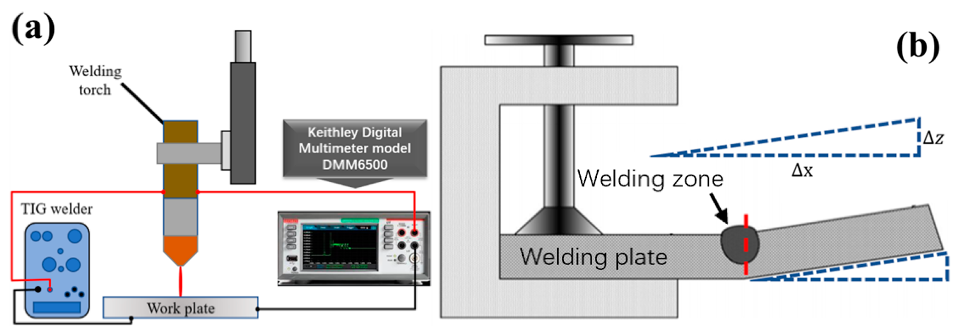
2.3. Fluxes Preparation and A-TIG Welding Process

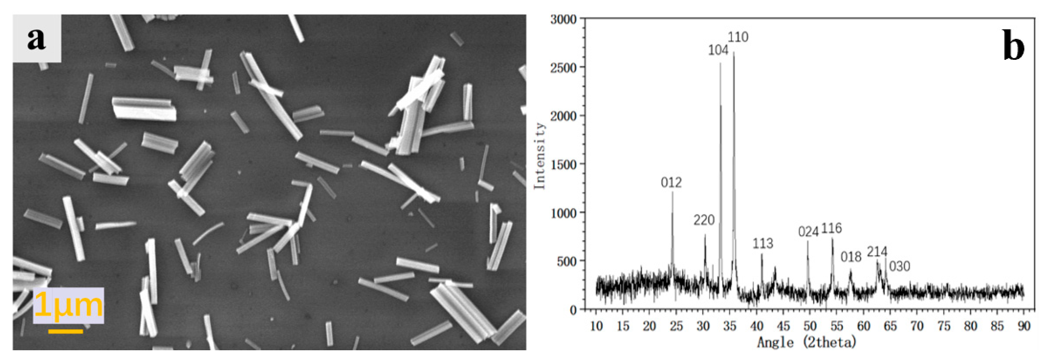
2.3.1. Nanoscale Fe2O3 Synthesis

α-Fe2O3 nanowires were synthesized via two steps [41,42]. In brief, Fe-based complex precursor nanowires were prepared. 0.15 M FeCl3 aqueous solution was mixed with isopropanol, to which 3 mmol nitrilotriacetic acid (NTA) was added. After magnetic stirring, the mixture was transferred into a Teflon-lined autoclave and hydrothermally treated at 190 °C for 24 h. The resultant white sediment was collected by centrifugation, washed with deionized water and absolute ethanol twice, and dried at 60 °C. In the second step, the precursors were put in a crucible and annealed at 350 °C for 1 h. After that, the precursors were converted into α-Fe2O3 nanowires. The width of α-Fe2O3 nanowires was around 25 nm, and the length was around 2–3 μm, as Figure 1a shows. Figure 1b shows XRD results of Fe2O3 nanowire. The peaks can be indexed by the anatase phase corresponding to the JCPDS card no. 39-0238.

2.3.2. A-TIG Welding Process

Two kinds of fluxes were made in this study: nanoscale and microscale Fe2O3 flux. Nanowire flux was mixed with nanoscale Fe2O3 and acetone in different mass ratios (Fe2O3/acetone = 1:1, 1:5 and 1:10), and microscale Fe2O3 flux was made with microscale Fe2O3 and acetone (commercial microscale Fe2O3 powders, Sigma Aldrich) as shown in Figure 2a. After mixing with a mechanical stirring with a Teflon puddler, the fluxes were applied by using a spray gun on the surface of the HMS steel plates to be welded. The coating thickness was thin enough to mask the joint line. The total quantity of flux required is 5–6 mg. After a few minutes, the flux coating was visibly dry, then the acetone evaporates, leaving a layer of flux adhering to the surface. Figure 2b shows a schematic diagram of activated TIG welding with a robotic stage and Figure 2c is an image of the real experiment set up. The welds were made with a fixed stand-off distance (also named arc length, L) of 3 mm from the tip of the tungsten to the workpiece. The arc was moved along the centerline of the test specimen and welds were carried out in the flat position on a single plate which was coated with the flux. During A-TIG welding, a part of or all of the fluxes were molten and vaporized.
Two sets of welding experiments were performed. At first, nanoscale Fe2O3 flux of different concentrations was applied onto the samples, the welding speed was 120 mm/min in this set. After that, a certain ratio should be decided for both nanoscale and microscale fluxes for welding set No. 2, this time the welding speed was 60 mm/min.

2.4. Measurement of Arc Voltage and Angular Distortion

During and after welding, investigations were carried out to measure the arc voltage and angular distortion in the A-TIG welded joints. The arc voltage is the voltage between cathode and anode during welding, and it can be measured by multimeter set between the material and tungsten electrode. The schematic figure of the arc voltage measuring set up is shown in Figure 3a.
The schematic for the angular distortion measuring setup is shown in Figure 3b. During measurement, the dial gauge was moved along the x-axis from the weld center to the edge of the plate through a distance Δx. Subsequently, a vertical displacement Δz was obtained in the dial gauge. The angular distortion values were measured before and after welding three times for each sample, and the average value was recorded. The differences in measurement before and after welding revealed the vertical displacement caused by welding; subsequently, the angular distortion value θ was calculated using the following equation:
θ = tan 1 ( Δ z Δ x )

3. Results and Discussion

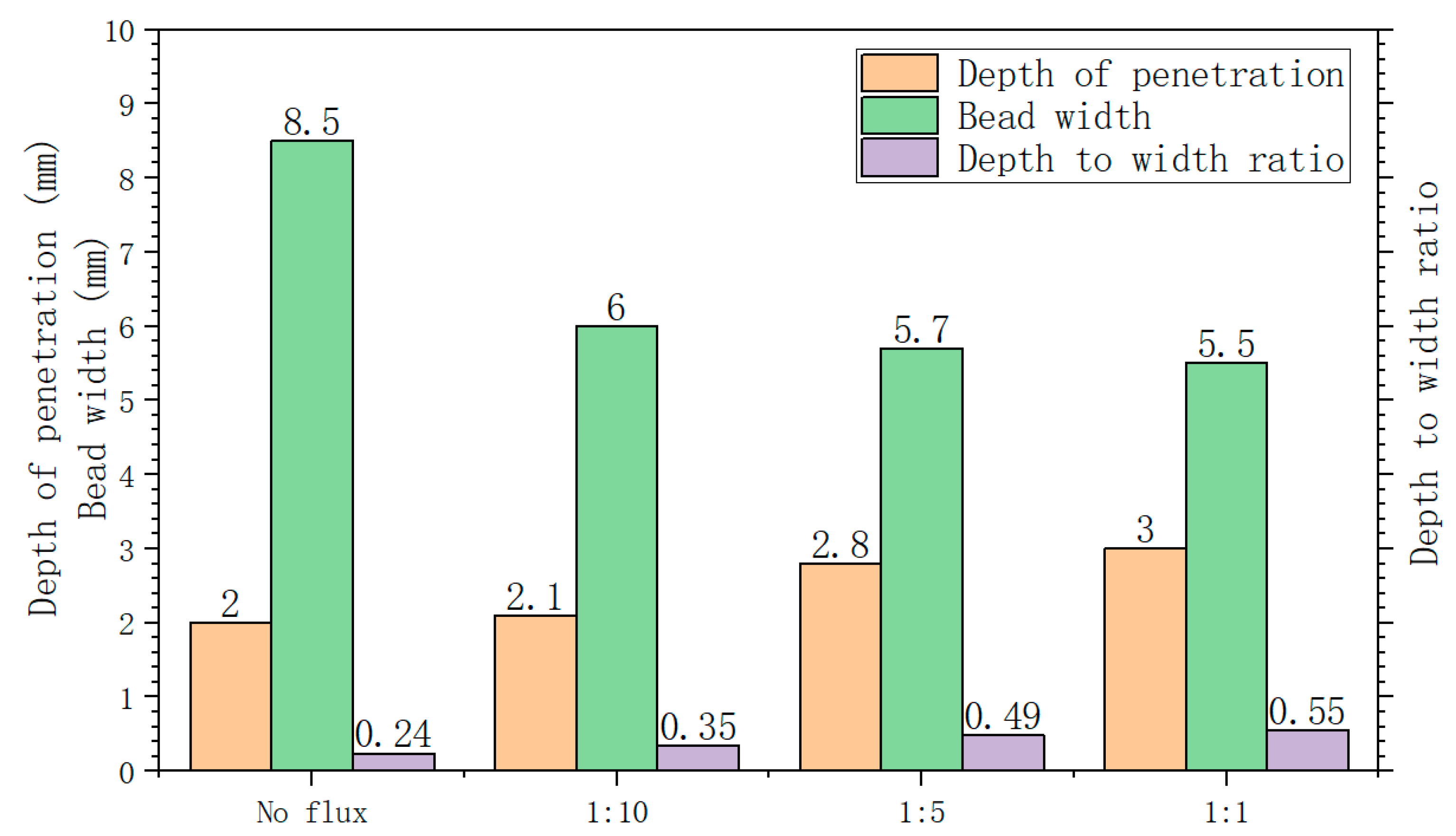
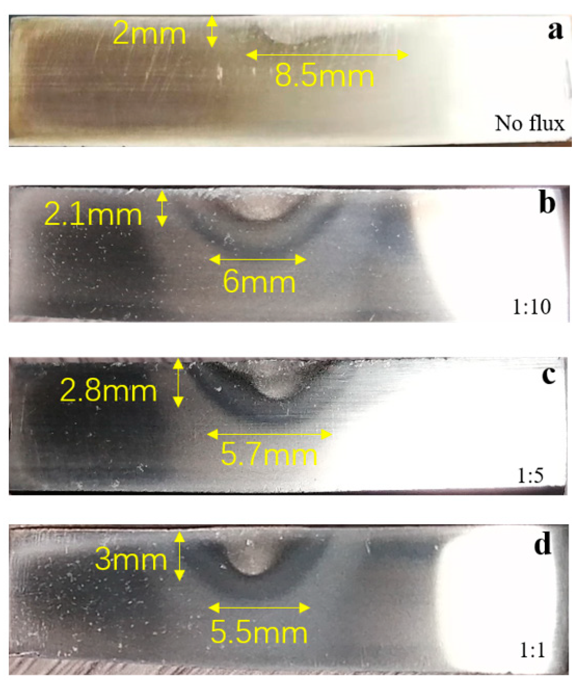
3.1. Effects of Fluxes Concentration on Weld Bead Geometry

The weld bead geometries of different concentration fluxes are shown in Figure 4a–d, at a speed of 120 mm/min. It can be observed that all the fluxes increased the depth of penetration (d) and reduced the bead width (w), as compared to the TIG weld without flux. The extent of their effect on weld bead parameters is characterized. The effect of various fluxes on depth of penetration (d), bead width (w), and depth of penetration to bead width ratio (d/w) are shown in Figure 5. TIG welding without flux results in the widest (8.5 mm) and shallowest (2 mm) weld bead with the lowest d/w ratio of 0.24. Whereas, the use of 1:1 flux results in the greatest depth of penetration (3 mm) with a d/w ratio of 0.55. The Fe2O3 flux with the ratio of 1:5 was found to yield the depth of penetration, bead width and d/w ratio as 2.8 mm, 5.7 mm and 0.49, respectively. As can be observed from the result, the depth of penetration, bead width and the d/w ratio all improve when the concentration of the flux grows increases. However, as flux reaches the 1:1 ratio, the change in the results also gradually reach a limit. Thus, the most concentrated one (1:1) was chosen for further characterization of the full penetration and the maximum d/w ratio.

3.2. Effects of Fluxes Composition on Weld Bead Geometry

The weld bead geometries of different composition fluxes are shown in Figure 6a–c, at a welding speed of 60 mm/min. It can be observed from Figure 6b,c that the bead width reduced drastically in the flux-coated region. The depth-to-width ratio of the microscale and nanowire fluxes welds were measured as 1.086 and 1.03, respectively. As the result shows, under the same welding condition, the nanowire flux reached better depth of penetration, but the microscale flux has a slightly higher d/w ratio.

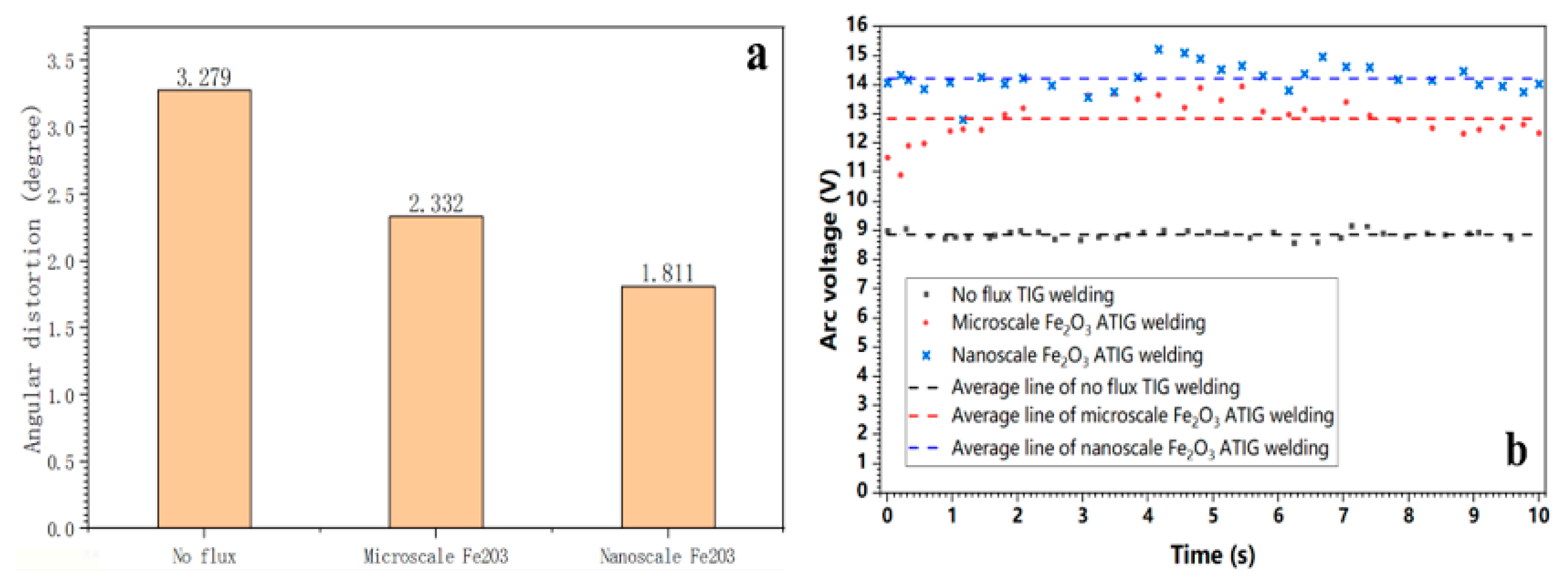
3.3. Effects of Flux on Angular Distortion and Heat Input

The angular distortion of the weldment is a result of the expansion and contraction of the weld metal and the adjacent base material during welding thermal cycles. Uneven heating through the thickness of a joint plate during welding causes non-uniform transverse shrinkage, yielding angular distortion of the weldment. The measured angular distortion in three different weld samples is shown in Figure 7a. Comparing with TIG welding without flux, activated TIG welding increases both the joint penetration and the weld depth-to-width ratio, which indicates a lower mechanical deformation during activated TIG welding. By combing the following input energy analysis, this can be contributed to a high localization of supplied heat, which prevents overheating of the base material and reduces the incidence of thermal stress and incompatible strain due to shrinkage in thickness. Therefore, the activated TIG welding can significantly reduce the angular distortion of the weldment.
The arc voltage vs. time graph during welding with and without fluxes are shown in Figure 7b. It was observed that the average arc voltage increased with use of activating fluxes. The average arc voltages observed without flux, with microscale flux and with nanowire flux welding were 8.869 V, 12.843 V and 14.227 V, respectively. The activating flux coating on the plate surface is believed to act as an electric current insulator between the plate and the tungsten electrode because of the high electrical resistivity of the fluxes. Therefore, arc voltage increases to maintain the smooth flow of current. According to the heat input equation [43]:
H = I V S
where H = heat input per unit weld length (J/mm), I =welding current (A), V = welding voltage (V), S =welding speed (mm/s). Since the welding speed and current between three samples are the same, increasing the arc voltage will surely increase the heat input, thus increasing the welding performance. The heat input calculated during welding without flux, with microscale flux, and with nanowire flux were 1.774 kJ/mm, 2.568 kJ/mm, and 2.845 kJ/mm, respectively. Comparing with the previous study reported by Ravi Shanker’s group [43] with the heat input of 2.757 kJ/mm (with flux), the nanoflux slightly increases the heat input into the steel plate.

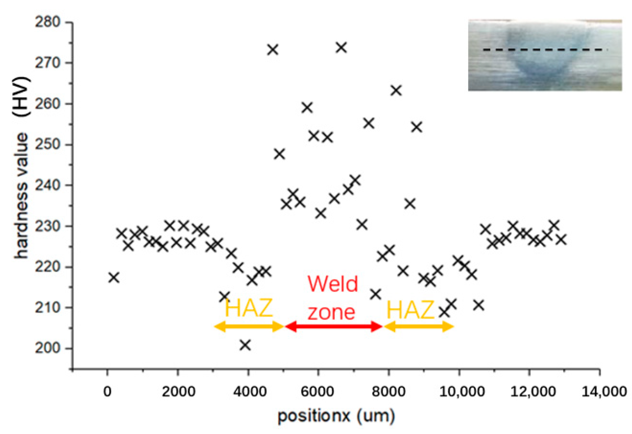
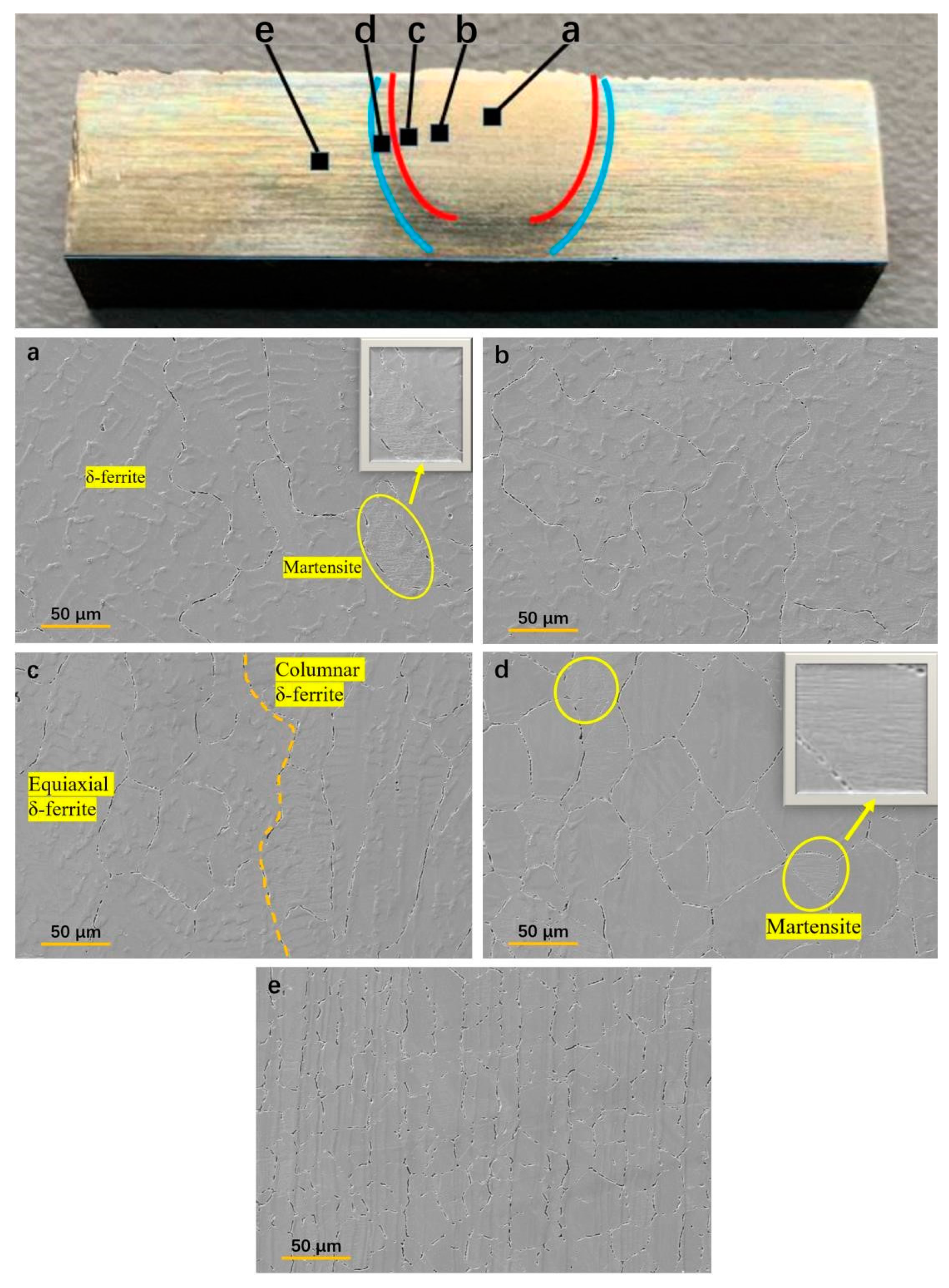
3.4. Microstructure Evolution

ATIG welding is autogenous welding, therefore, columnar and epitaxial grain growth was expected in the weld fusion zone from the weld fusion boundary. SEM microstructures showing grain size of the different weld zone of the A-TIG nanoscale Fe2O3 flux weldments are shown in Figure 8, where a–e indicate welding zone to base metal. Among the welding zone the grains mainly consisted of equiaxed (a, b) and columnar (c) grain structures with δ-ferrite. The grains in the heat effect zone (HAZ) (d) and base material (e) were still dominant austenite, but some coarse austenite grains transformed to coarse untempered martensite grains during subsequent cooling in welding zone and HAZ area (see Figure 8a,d, yellow circle) which may increase the hardness. The A-TIG weld fusion zone solidifies as the coarse grain, with the size of around 100–120 μm. Comparing with grain size of 70–85 μm [43,44] in stainless steel of normal TIG welding, grains of ATIG with nanoscale Fe2O3 flux are coarser due to the higher heat input during welding in the A-TIG joint than that in TIG joint. Homogenous grain structure throughout the weld fusion zone (from zone a to part of zone c) is observed owing to the single pass autogenous welding. The grain size measurement shows that from zone (a) to zone (c) the average grain size keeps decreasing from 120 μm to around 70 μm, but that is still much larger than that of the base metal (around 25 μm). The large columnar grain in zone (c) should arise from the large temperature gradient in the heat effect zone. The overall larger grain sizes in zones (a, b, c) can be attributed to the resolidification from a higher temperature and larger heat input in ATIG welding than that of a conventional TIG welding.

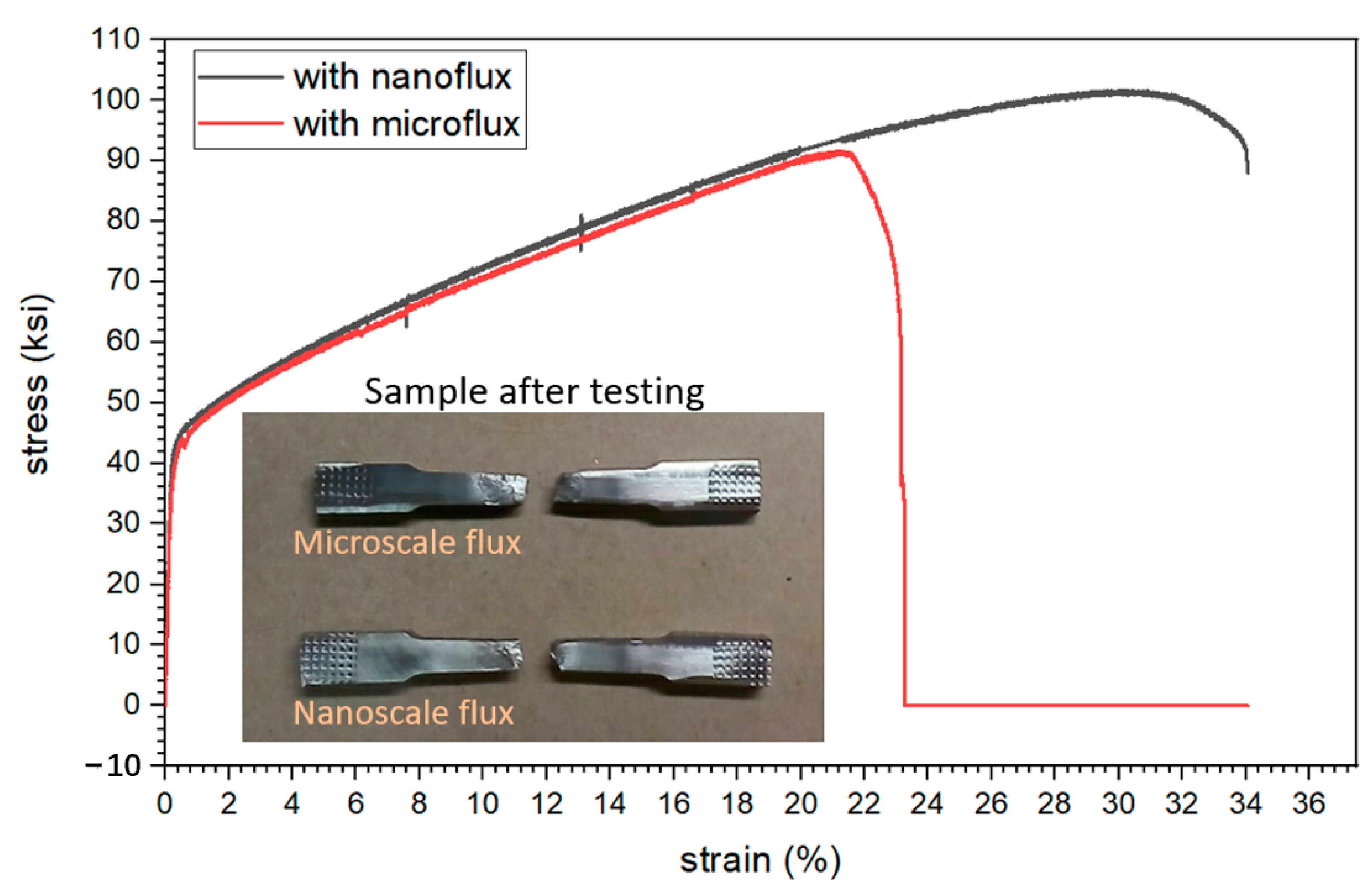
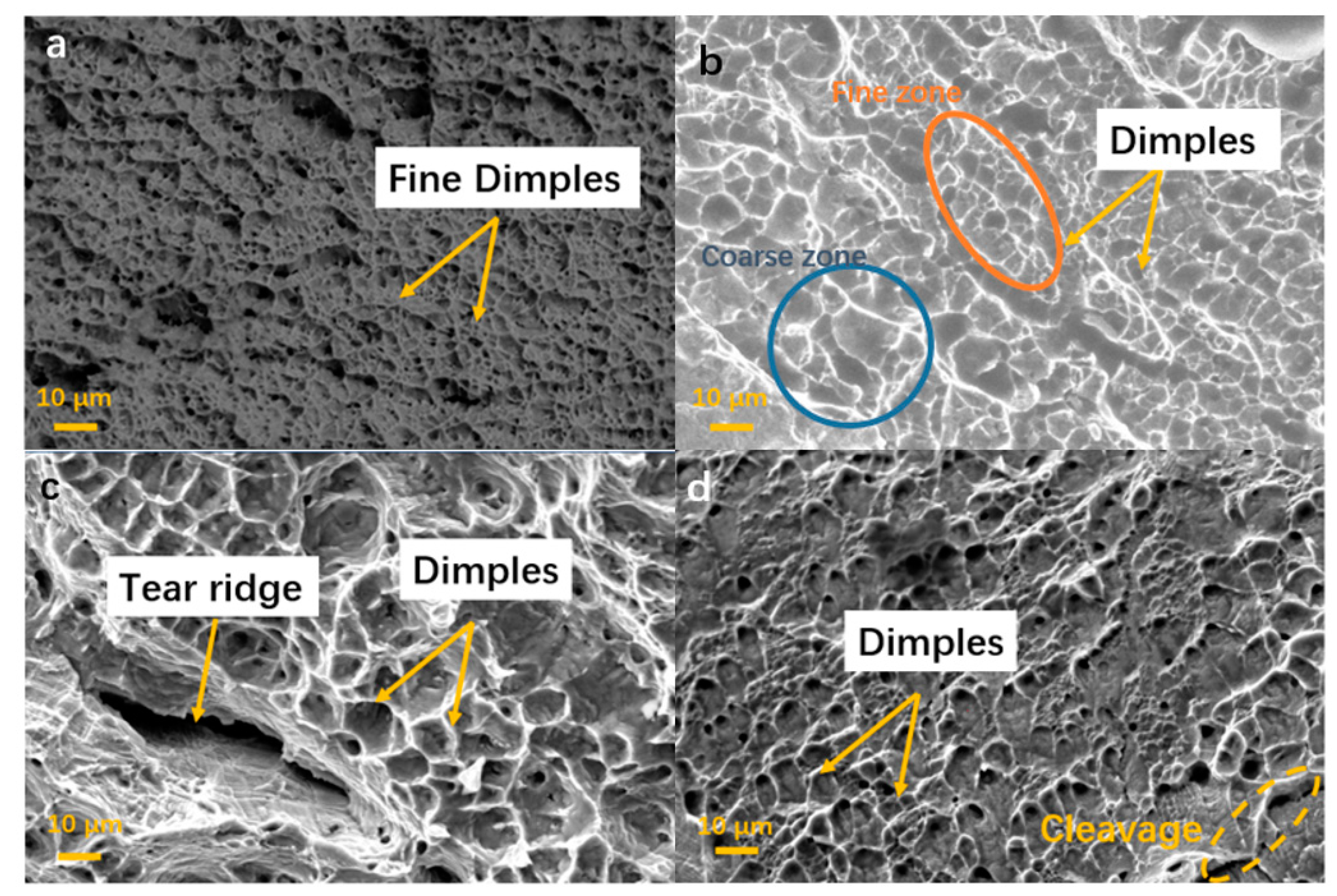
3.5. Mechanical Properties

The tensile test was performed on as-received base metals and the weld joints, two samples were tested in each condition and the average value was reported. The tensile test samples after test are shown in Figure 9. The tensile strength and elongation of the microscale flux weld sample was 630.8 MPa and 21.5%; and the tensile strength and elongation of the nanowire flux weld sample was 700.23 MPa and 34.1%, respectively. Whereas, the tensile strength and elongation of HMS base metal were measured as 850 MPa and 50%, respectively. It was observed that the strength of the nanowire flux weld sample was similar to the HMS base metal and had a much higher elongation parameter than the microscale flux welded sample.
The joint efficiency of the microscale flux was calculated as:
Joint efficiency = (Strength of welding sample)/(Strength of HMS) = 630.8/850 × 100% = 74.2%.
The joint efficiency of the nanowire flux was calculated as:
Joint efficiency = (Strength of welding sample)/(Strength of HMS) = 700.23/850 × 100% = 82.38%
However, the percentage strain obtained for both welds was lower than the base metal. The increased tensile strength and reduced ductility of the A-TIG welds was attributed to the martensitic formation and larger grain size. Moreover, the hardness result (shown in Figure 10) is also in good agreement with the microstructure studies, as larger grains possess a lower hardness. The increased hardness (higher than base metal) in the A-TIG weld zone and part of HAZ was attributed to its microstructural transformation from austenitic to martensitic. The other part of HAZ has lower hardness due to the tempering of the existed martensite caused by the weld thermal cycle and absence of lath martensite.
SEM images of the tensile test fracture surfaces among welding zone are shown in Figure 11. The fracture surface of the as-received base metal (Figure 11a), the TIG welding joint without flux (Figure 11b), and the A-TIG with microscale Fe2O3 flux and nanoscale Fe2O3 flux weldments failed from the welding joint (Figure 11c,d) were found dissimilar in morphological nature. Multiple fine dimples were observed on the fracture surface from the base metal, which indicates strong tensile strength and elongation. The sizes of the dimples were calculated and proved to be different. First, the base metal had the finest size of dimples (average 3.52 μm). As for the normal TIG welding without flux, it had a larger average dimple size (5.76 μm) than the base metal, which may arise from the coarsening grain size in the welding zone. There are some fine dimple zones coexisting with big size dimples in the conventional TIG weld joints. For the A-TIG welding sample fracture surfaces with either micro- or nanofluxes, both have larger dimples than the TIG welding samples since the higher heat input increased the grain size among the welding zone. However, the nanoscale Fe2O3 flux sample has finer average dimple sizes (6.02 μm) than microscale Fe2O3 flux sample (7.67 μm). This is consistent with the data which the nanoscale Fe2O3 flux welding sample has higher elongation compared with microscale one.

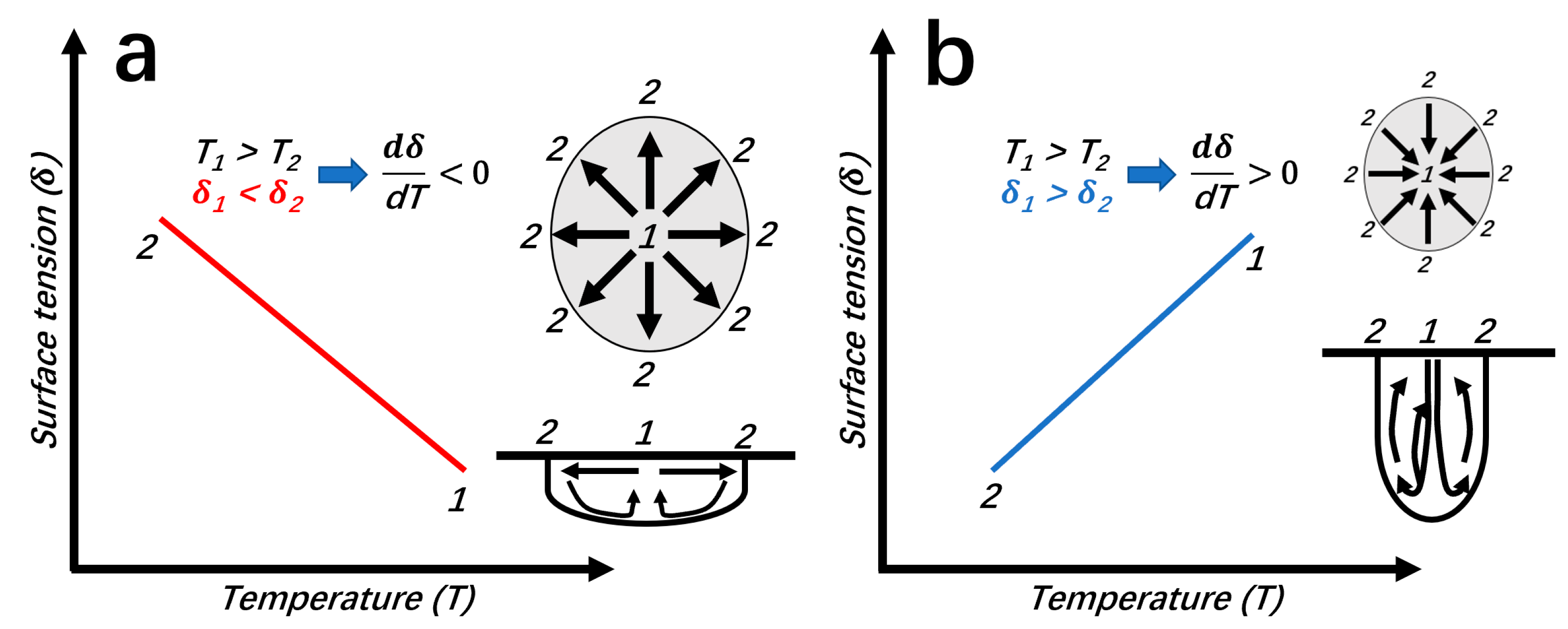
3.6. Mechanism on Nanowire Flux Activated TIG Welding

Generally, in a TIG welding process, there are several kinds of forces driving the melting metal flow and forging a shape of the welding pool [45,46]. Those forces include shear force, Marangoni force, Lorentz force, and Buoyant force. However, during these forces, Lorentz force and Buoyant force are much weaker than the other dominant forces (shear force and Marangoni force) and thus are not considered to be dominant in TIG welding. Shear force is strong, but it always occurs in the downward direction. Thus, the Marangoni force, which can change direction and the shape of the welding pool as a dominant driving force, will be mainly discussed in this study.
The difference in weld bead geometry of without-flux and with-flux weldments can be related with the heat input, and the reversal in Marangoni convection shown in Figure 12. The Marangoni flow is determined by the non-dimensional Marangoni number (Ma) defined in the following equation [47]:
M a = d γ d T d T d x L 2 η a
where (/dT) is the surface tension gradient, (dT/dx) is the temperature gradient, η is the viscosity, a is the thermal diffusivity and L is the characteristic length.
The surface tension gradient (dγ/dT) determines the direction of the flow, and it can produce Marangoni forces on the surface of a welding pool. Previous study showed that when the temperature is around 2000 K or less, the value of (dγ/dT) will be negative and decrease with increasing temperature. In this condition, the surface tension shows the maximum value at the edge of the welding pool (since the temperature there is the lowest) and will create a convective flow from the center toward the edge as Figure 12a shows. Under this upward and backward flow around the top surface, an outward surface flow resulting in a wide, shallow welding molten pool will be induced.
However, when adding flux (usually oxide compounds) the O (or S) content in-creases near the welding pool, which leads to a positive (/dT). Thus, the surface tension is greatest in the high-temperature region (at the center of the welding pool) and induces a radial inward flow (downward around the bottom surface of the welding pool). This means that the welding molten metal produces a downward flow starting from the welding pool center, yielding a deep and narrow pool (Figure 12b). Based on the temperature gradient part (dT/dx), which determined the strength of the flow, it is obvious that for a similar T, as dx is lower, the value of (dT/dx) part will increase and thus increase the value of the flow force, which results in a deep welding penetration. Compared with no-flux TIG welding, both microscale and nanowire flux have a lower dx, and contribute to improved penetration.
Based on the study, for nanowire flux, the dT/dx value is higher than that of microscale flux. This could be attributed to the size effect of melting point [36,49]. Due to the surface and quantum confinement effects of nanomaterials [50], there are fewer “neighbors” around the atoms at the surface than a microparticle, result in a lower binding energy per atom. The reduction of binding energy per atom results in a lower Gibbs free energy of oxides. Thus, the nanowire flux exhibits a lower thermal stability than microscale flux, indicating a higher dissolving rate under the same temperature and sufficient oxygen content for a more pronounced reversed Marangoni convection. It was also evident that the nanowire flux has a high heat input than microscale flux under the same current (Figure 7b), which results in a higher melting pool temperature, a high dT/dx and thereby a stronger Marangoni flow for a deeper penetration.

4. Conclusions

An 8-millimeter-thick HMS plate was successfully welded in single pass using Fe2O3 modified flux. A significant increase in joint penetration was obtained with both microscale and nanoscale Fe2O3-based fluxes as compared to the conventional TIG weldments. The nanowire flux displays significant improvement of input energy efficiency, tensile strength and strain compared to a microflux. The mechanism is attributed to the low melting temperature of nanowire flux and strong reversal Marangoni flow in the melting pool.

Author Contributions

Conceptualization, L.Z. and A.H.; methodology, L.Z.; data curation, L.Z.; writing—original draft preparation, L.Z.; writing—review and editing, L.Z. and A.H.; project administration, A.H. All authors have read and agreed to the published version of the manuscript.

Funding

This research was funded by POSCO company, grant number R011373710.

Acknowledgments

The authors thank the financial support from POSCO company for providing a research grant and relevant materials, and are grateful for discussions with Wookil Jang from POSCO, Zhili Feng and Yong-Chae Lim at Oak Ridge National Lab.

Conflicts of Interest

The authors declare no conflict of interest.

References

  1. Singh, A.K.; Dey, V.; Rai, R.N. Techniques to improveweld penetration in TIG welding (A review). Mater. Today Proc. 2017, 4, 1252–1259. [Google Scholar] [CrossRef]
  2. Nguyen, V.N.; Nguyen, Q.M.; Huang, S.-C. Microstructure and mechanical properties of butt joints between stainless steel SUS304L and aluminum alloy A6061-T6 by TIG welding. Materials 2018, 11, 1136. [Google Scholar] [CrossRef] [Green Version]
  3. Chandrasekhar, N.; Ragavendran, M.; Ravikumar, R.; Vasudevan, M.; Murugan, S. Optimization of hybrid laser–TIG welding of 316LN stainless steel using genetic algorithm. Mater. Manuf. Process. 2017, 32, 1094–1100. [Google Scholar] [CrossRef]
  4. Singh, S.R.; Khanna, P. A-TIG (activated flux tungsten inert gas) welding:–A review. Mater. Today Proc. 2021, 44, 808–820. [Google Scholar] [CrossRef]
  5. Zou, Y.; Xu, Y.; Hu, Z.; Gu, X.; Peng, F.; Tan, X.; Chen, S.; Han, D.; Misra, R.; Wang, G. Austenite stability and its effect on the toughness of a high strength ultra-low carbon medium manganese steel plate. Mater. Sci. Eng. A 2016, 675, 153–163. [Google Scholar] [CrossRef]
  6. Saeed-Akbari, A.; Imlau, J.; Prahl, U.; Bleck, W. Derivation and variation in composition-dependent stacking fault energy maps based on subregular solution model in high-manganese steels. Metall. Mater. Trans. A 2009, 40, 3076–3090. [Google Scholar] [CrossRef]
  7. Chen, L.; Zhao, Y.; Qin, X. Some aspects of high manganese twinning-induced plasticity (TWIP) steel, a review. Acta Metall. Sin. 2013, 26, 1–15. [Google Scholar] [CrossRef] [Green Version]
  8. Mahlami, C.S.; Pan, X. An Overview on high manganese steel casting. In Proceedings of the World Foundry Congrees 2014, Bilbao, Spain, 19–21 May 2014; pp. 1–10. [Google Scholar]
  9. Haase, C.; Kremer, O.; Hu, W.; Ingendahl, T.; Lapovok, R.; Molodova, D.A. Equal-channel angular pressing and annealing of a twinning-induced plasticity steel: Microstructure, texture, and mechanical properties. Acta Mater. 2016, 107, 239–253. [Google Scholar] [CrossRef]
  10. Allain, S.; Scott, C.P.; Cugy, P.; Barbier, D. High manganese austenitic twinning induced plasticity steels: A review of the microstructure properties relationships. Curr. Opin. Solid State Mater. Sci. 2011, 15, 141–168. [Google Scholar]
  11. Sabzi, M.; Farzam, M. Hadfield manganese austenitic steel: A review of manufacturing processes and properties. Mater. Res. Express 2019, 6, 1065c2. [Google Scholar] [CrossRef]
  12. Sasaki, T.; Watanabe, K.; Nohara, K.; Ono, Y.; Kondo, N.; Sato, S. Physical and mechanical properties of high manganese non-magnetic steel and its application to various products for commercial use. Trans. Iron Steel Inst. Jpn. 1982, 22, 1010–1020. [Google Scholar] [CrossRef]
  13. Takahashi, H.; Shindo, Y.; Kinoshita, H.; Shibayama, T.; Ishiyama, S.; Fukaya, K.; Eto, M.; Kusuhashi, M.; Hatakeyama, T.; Sato, I. Mechanical properties and damage behavior of non-magnetic high manganese austenitic steels. J. Nucl. Mater. 1998, 258, 1644–1650. [Google Scholar] [CrossRef]
  14. Ma, B.; Li, C.; Zheng, J.; Song, Y.; Han, Y. Strain hardening behavior and deformation substructure of Fe–20/27Mn–4Al–0.3 C non-magnetic steels. Mater. Des. 2016, 92, 313–321. [Google Scholar] [CrossRef]
  15. Roshan, J.; Sankaranarayanan, S.R.; Babu, S.P.K. Recent advancements in manganese steels—A review. Mater. Today Proc. 2020, 27, 2852–2858. [Google Scholar]
  16. Yoo, J.; Han, K.K.; Choi, J. Evaluation of solidification cracking susceptibility of Fe–18Mn–0· 6C steel welds. Sci. Technol. Weld. Join. 2014, 19, 514–520. [Google Scholar] [CrossRef]
  17. García-García, V.; Mejía, I.; Reyes-Calderón, F. Comparative study on weldability of Ti-containing TWIP and AISI 304L austenitic steels through the autogenous-GTAW process. Int. J. Adv. Manuf. Technol. 2018, 98, 2365–2376. [Google Scholar] [CrossRef]
  18. Khan, P.A.A.; Debroy, T.; David, S.A. Laser Beam Welding of High-Manganese Stainless Steels-Examination of Alloying Element Loss and Microstructural Changes. Weld. J. 1988, 67, 1–7. [Google Scholar]
  19. Mujica, L.; Weber, S.; Thomy, C.; Vollertsen, F. Microstructure and mechanical properties of laser welded austenitic high manganese steels. Sci. Technol. Weld. Join. 2009, 14, 517–522. [Google Scholar] [CrossRef]
  20. Martin, D.; Daamen, M.; Hirt, G. Laser beam welding of high manganese TWIP steels produced by twin roll strip casting. In Proceedings of the Extended Abstract: 2nd International Conference on High Manganese Steel, Aachen, Germany, 31 August 2014. [Google Scholar]
  21. Lun, N.; Saha, D.; Macwan, A.; Pan, H.; Wang, L.; Goodwin, F.; Zhou, Y.; Lun, N.; Saha, D.; Macwan, A.; et al. Microstructure and mechanical properties of fibre laser welded medium manganese TRIP steel. Mater. Des. 2017, 131, 450–459. [Google Scholar] [CrossRef]
  22. Heidarzadeh, A.; Mironov, S.; Kaibyshev, R.; Çam, G.; Simar, A.; Gerlich, A.; Khodabakhshi, F.; Mostafaei, A.; Field, D.; Robson, J.; et al. Friction stir welding/processing of metals and alloys: A comprehensive review on microstructural evolution. Prog. Mater. Sci. 2020, 117, 100752. [Google Scholar]
  23. Singh, K.; Singh, G.; Singh, H. Review on friction stir welding of magnesium alloys. J. Magnes. Alloys 2018, 6, 399–416. [Google Scholar] [CrossRef]
  24. Singh, V.P.; Patel, S.K.; Ranjan, A.; Kuriachen, B. Recent research progress in solid state friction-stir welding of aluminium–magnesium alloys: A critical review. J. Mater. Res. Technol. 2020, 9, 6217–6256. [Google Scholar] [CrossRef]
  25. Chen, G.; Zhang, S.; Zhu, Y.; Yang, C.; Shi, Q. Thermo-mechanical analysis of friction stir welding: A review on recent advances. Acta Metall. Sin. 2020, 33, 3–12. [Google Scholar] [CrossRef] [Green Version]
  26. Morisada, Y.; Fujii, H.; Xukun, N. Development of simplified active flux tungsten inert gas welding for deep penetration. Mater. Des. 2014, 54, 526–530. [Google Scholar] [CrossRef]
  27. Li, H.; Zou, J.; Yao, J.; Peng, H. The effect of TIG welding techniques on microstructure, properties and porosity of the welded joint of 2219 aluminum alloy. J. Alloys Compd. 2017, 727, 531–539. [Google Scholar] [CrossRef]
  28. Patel, D.; Jani, S. ATIG welding: A small step towards sustainable manufacturing. Adv. Mater. Process. Technol. 2020, 1–23. [Google Scholar] [CrossRef]
  29. Klobčar, D.; Bizjak, M.; Simončič, S.; Lešer, V. Active flux tungsten inert gas welding of austenitic stainless steel AISI 304. Metalurgija 2016, 55, 617–620. [Google Scholar]
  30. Kumar, K.; Deheri, S.C.; Masanta, M. Effect of activated flux on TIG welding of 304 austenitic stainless steel. Mater. Today Proc. 2019, 18, 4792–4798. [Google Scholar] [CrossRef]
  31. Babbar, A.; Kumar, A.; Jain, V.; Gupta, D. Enhancement of activated tungsten inert gas (A-TIG) welding using multi-component TiO2-SiO2-Al2O3 hybrid flux. Measurement 2019, 148, 106912. [Google Scholar] [CrossRef]
  32. Tathgir, S.; Bhattacharya, A. Activated-TIG welding of different steels: Influence of various flux and shielding gas. Mater. Manuf. Process. 2016, 31, 335–342. [Google Scholar] [CrossRef]
  33. Sambherao, A.B. Use of activated flux for increasing penetration in austenitic stainless steel while performing GTAW. Int. J. Emerg. Technol. Adv. Eng. 2013, 3, 520–524. [Google Scholar]
  34. Dhandha, K.H.; Badheka, V.J. Effect of activating fluxes on weld bead morphology of P91 steel bead-on-plate welds by flux assisted tungsten inert gas welding process. J. Manuf. Process. 2015, 17, 48–57. [Google Scholar] [CrossRef]
  35. Singh, A.K.; Kumar, M.; Dey, V.; Rai, R.N. A Study to Increase Weld Penetration in P91 Steel during TIG Welding by Using Activating Fluxes. IOP Conference Series: Materials Science and Engineering; No. 1; IOP Publishing: Bristol, UK, 2017; Volume 225. [Google Scholar]
  36. Touileb, K.; Hedhibi, A.; Djoudjou, R.; Ouis, A.; Bouazizi, M.L. Mixing design for ATIG morphology and microstructure study of 316L stainless steel. Eng. Technol. Appl. Sci. Res. 2019, 9, 3990–3997. [Google Scholar] [CrossRef]
  37. Chandrasekar, G.; Kailasanathan, C.; Vasundara, M. Investigation on un-peened and laser shock peened dissimilar weldments of Inconel 600 and AISI 316L fabricated using activated-TIG welding technique. J. Manuf. Process. 2018, 35, 466–478. [Google Scholar] [CrossRef]
  38. Hu, A.; Janczak-Rusch, J.; Sano, T. Joining technology innovations at the macro, micro, and nano levels. Appl. Sci. 2019, 9, 3568. [Google Scholar] [CrossRef] [Green Version]
  39. Bridges, D.; Nielsen, B.; Zhang, L.; Zhang, S.; Xu, R.; Hu, A. Wettability, Diffusion Behaviors, and Modeling of Ni Nanoparticles and Nanowires in Brazing Inconel 718. Adv. Eng. Mater. 2020, 2001053. [Google Scholar] [CrossRef]
  40. Tseng, K.-H.; Chen, C.-S. Characteristics of nanoscale active oxide in enhancing penetration capability of surfactant flux assisted TIG welding. J. Nanosci. Nanotechnol. 2017, 17, 1796–1805. [Google Scholar] [CrossRef]
  41. Wu, J.; Xue, S.; Bridges, D.; Yu, Y.; Zhang, L.; Pooran, J.; Hill, C.; Wu, J.; Hu, A. Fe-based ceramic nanocomposite membranes fabricated via e-spinning and vacuum filtration for Cd2+ ions removal. Chemosphere 2019, 230, 527–535. [Google Scholar] [CrossRef] [PubMed]
  42. Ren, L.; Zhou, W.; Sun, B.; Li, H.; Qiao, P.; Xu, Y.; Wu, J.; Lin, K.; Fu, H. Defects-engineering of magnetic γ-Fe2O3 ultrathin nanosheets/mesoporous black TiO2 hollow sphere heterojunctions for efficient charge separation and the solar-driven photocatalytic mechanism of tetracycline degradation. Appl. Catal. B Environ. 2019, 240, 319–328. [Google Scholar] [CrossRef]
  43. Vidyarthy, R.S.; Dwivedi, D.K. Microstructural and mechanical properties assessment of the P91 A-TIG weld joints. J. Manuf. Process. 2018, 31, 523–535. [Google Scholar] [CrossRef]
  44. Sakthivel, T.; Vasudevan, M.; Laha, K.; Parameswaran, P.; Chandravathi, K.; Mathew, M.; Bhaduri, A. Comparison of creep rupture behaviour of type 316L (N) austenitic stainless-steel joints welded by TIG and activated TIG welding processes. Mater. Sci. Eng. A 2011, 528, 6971–6980. [Google Scholar] [CrossRef]
  45. van Anh, N.; Tashiro1, S.; van Hanh, B.; Tanaka, M. Experimental investigation on the weld pool formation process in plasma keyhole arc welding. J. Phys. D Appl. Phys. 2017, 51, 015204. [Google Scholar] [CrossRef]
  46. Ngo Huu, M.; Nguyen Van, A.; Nguyen Van, T.; Tran Hai, D.; Nguyen Van, T.; Nguyen Tien, D.; Nguyen, T.H. Material flow behavior on weld pool surface in plasma arc welding process considering dominant driving forces. Appl. Sci. 2020, 10, 3569. [Google Scholar] [CrossRef]
  47. Mills, K.C.; Keene, B.J.; Brooks, R.F.; Shirali, A. Marangoni effects in welding. Philos. Trans. R. Soc. Lond. Ser. A Math. Phys. Eng. Sci. 1998, 356, 911–925. [Google Scholar] [CrossRef]
  48. Lu, S.; Fujii, H.; Sugiyama, H.; Tanaka, M.; Nogi, K. Weld penetration and Marangoni convection with oxide fluxes in GTA welding. Mater. Trans. 2002, 43, 2926–2931. [Google Scholar] [CrossRef] [Green Version]
  49. Anming, H. (Ed.) Laser Micro-Nano-Manufacturing and 3D Microprinting; Springer International Publishing AG: New York, NY, USA, 2020. [Google Scholar]
  50. Aline, L.S.; Dalpian, G.M. Cobalt-doped ZnO nanocrystals: Quantum confinement and surface effects from ab initio methods. Phys. Chem. Chem. Phys. 2013, 15, 15863–15868. [Google Scholar]
Figure 1. SEM photo (a) and XRD result (b) of as-grown Fe2O3 nanowires.
Applsci 11 05052 g001
Figure 2. (a) Spray coating of active flux to thick steel plate; (b) Schematic figure of A-TIG welding; (c) Photo of real experimental set up.
Applsci 11 05052 g002
Figure 3. Measurement configurations for (a) arc voltage and (b) angular distortion of TIG weldment.
Applsci 11 05052 g003
Figure 4. Weld bead geometry images of welded joints without fluxes, and with different concentrations of Fe2O3 nanowire fluxes ((a): no flux, (b): 1:10, (c): 1:5 and (d): 1:1) welding under speed of 120 mm/min.
Applsci 11 05052 g004
Figure 5. Weld bead geometry variation on different concentration fluxes (d/w ratio).
Applsci 11 05052 g005
Figure 6. Top: weld bead geometry photo of welded joints without fluxes (a), with Fe2O3 microscale (b) and Fe2O3 nanowire fluxes (c), welding speed of 60 mm/s. Below: weld bead geometry variation on different concentration fluxes (d/w ratio).
Applsci 11 05052 g006
Figure 7. Effect of activated flux on angular distortion of the weldment (a) and welding arc voltage (b).
Applsci 11 05052 g007
Figure 8. SEM microstructure of the fusion zone, HAZ and base material of nanoscale Fe2O3 flux weldments: (a) fusion zone 1; (b) fusion zone 2; (c) fusion zone 3; (d) heat-affected zone (HAZ); (e) base metal.
Applsci 11 05052 g008
Figure 9. Tensile stress vs. tensile strain curve for the nanowire flux and microscale flux weld joint.
Applsci 11 05052 g009
Figure 10. Microhardness profiles along X direction (nanowire flux).
Applsci 11 05052 g010
Figure 11. Tensile test fracture surface of (a) base metal, (b) no-flux TIG welding, (c) A-TIG weldments with microscale Fe2O3 flux, and (d) A-TIG weldments with nanoscale Fe2O3 flux.
Applsci 11 05052 g011
Figure 12. Schematic figure showing Marangoni flow in TIG welding: (a) without flux (b) with flux (redrawn from [48], © 2021, Lu, Shanping, et al.).
Applsci 11 05052 g012
Table 1. Composition of high manganese steel.
Chemical Composition (Mass %)
CMnPSSiCrCuBN
0.35–0.5522.5–25.5≤0.03≤0.010.1–0.50.3–0.40.3–0.7≤0.005≤0.05
Tensile properties
Yield strengthTensile strengthElongation
480 Mpa850 Mpa50%
Table 2. Welding parameters used for A-TIG.
Process ParametersValue
Electrode type2% thoriated (W with 2% thorium)
Electrode diameter2.4 mm
Electrode angle45°
Welding current200 A
Welding speed120 mm/min; 60 mm/min
Arc length3 mm
Shielding gas/flow rate99.99% Pure Argon/10 L min−1
Publisher’s Note: MDPI stays neutral with regard to jurisdictional claims in published maps and institutional affiliations.

