
A Feedrate Planning Method for the NURBS Curve in CNC Machining Based on the Critical Constraint Curve

 , , ,
, , ,
Abstract
1. Introduction
2. Feedrate Planning of a NURBS Curve Based on CCC
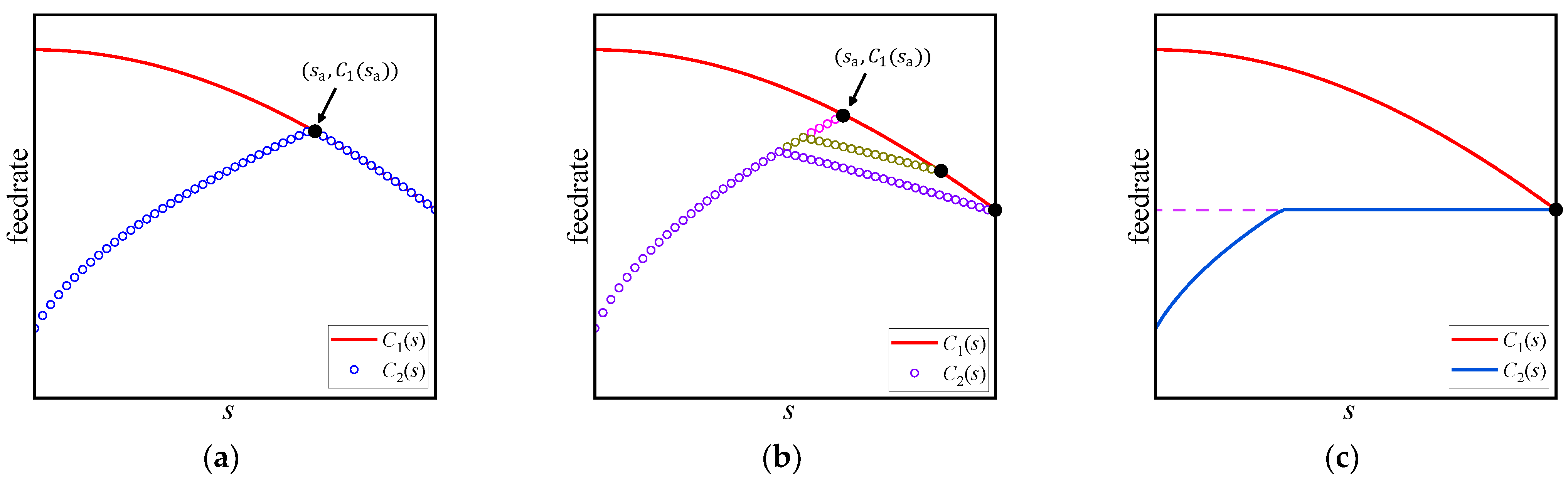
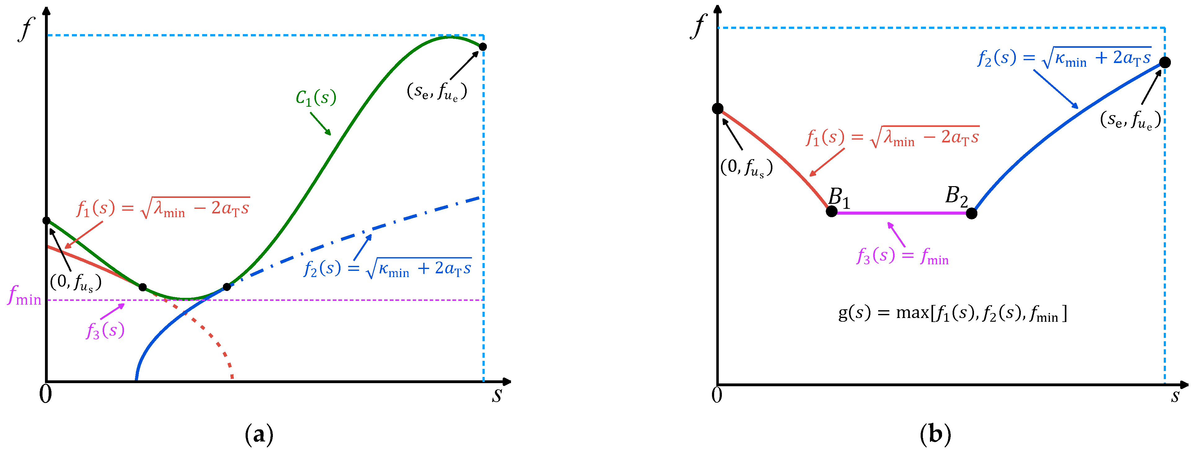
2.1. Problem Analysis of the Existing -Constructing Method
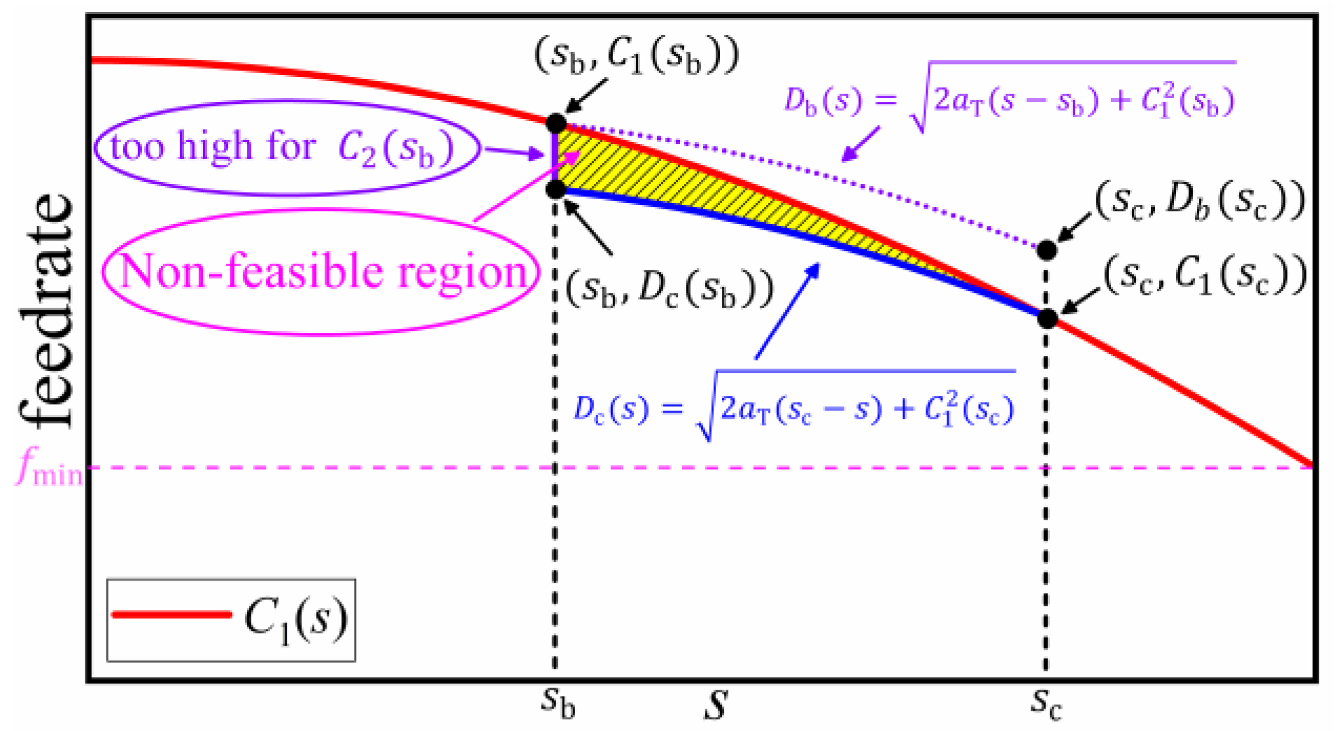
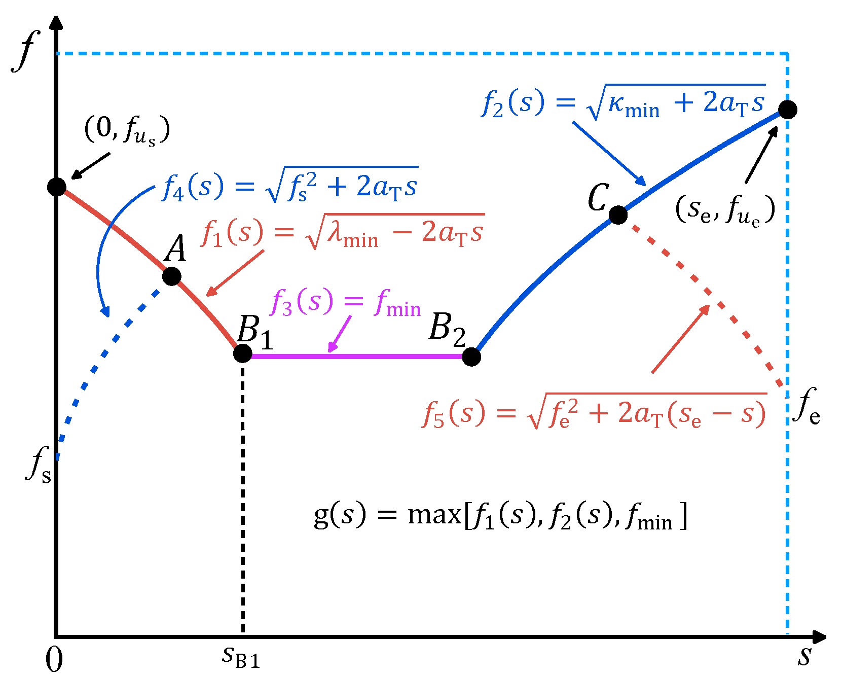
2.2. Establishment of the CCC Mathematical Model
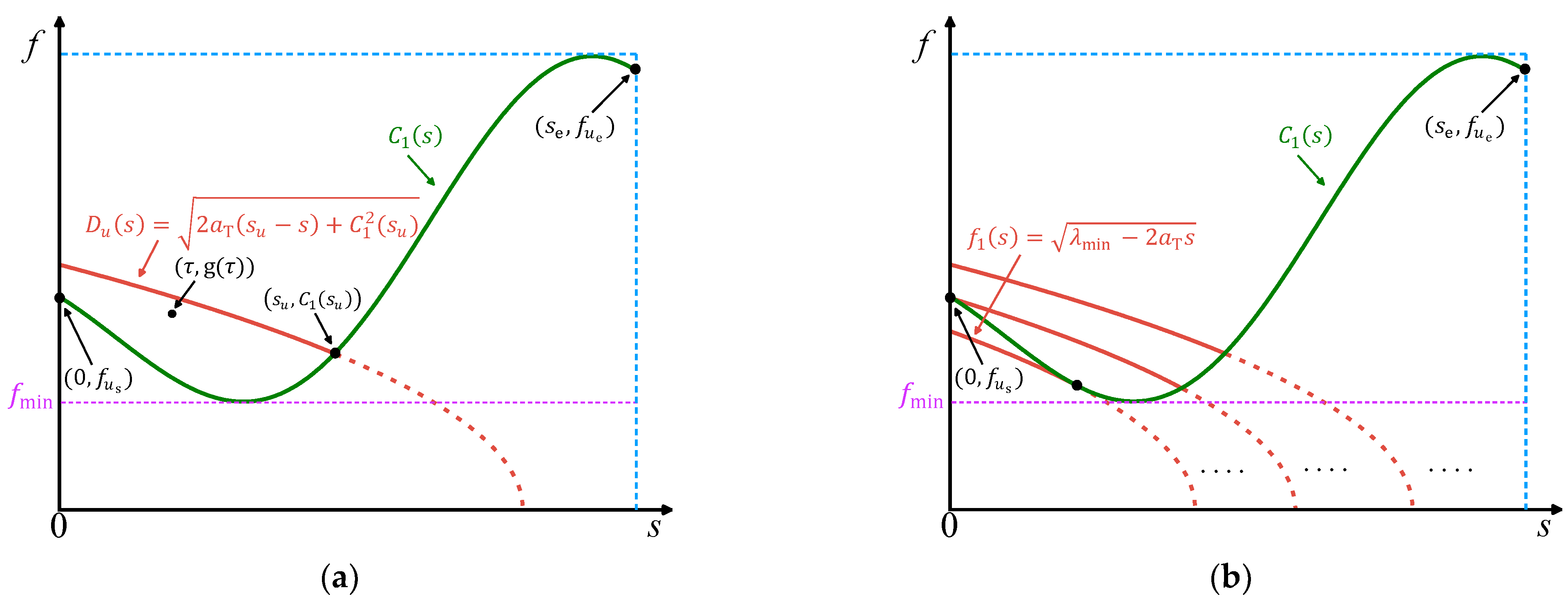
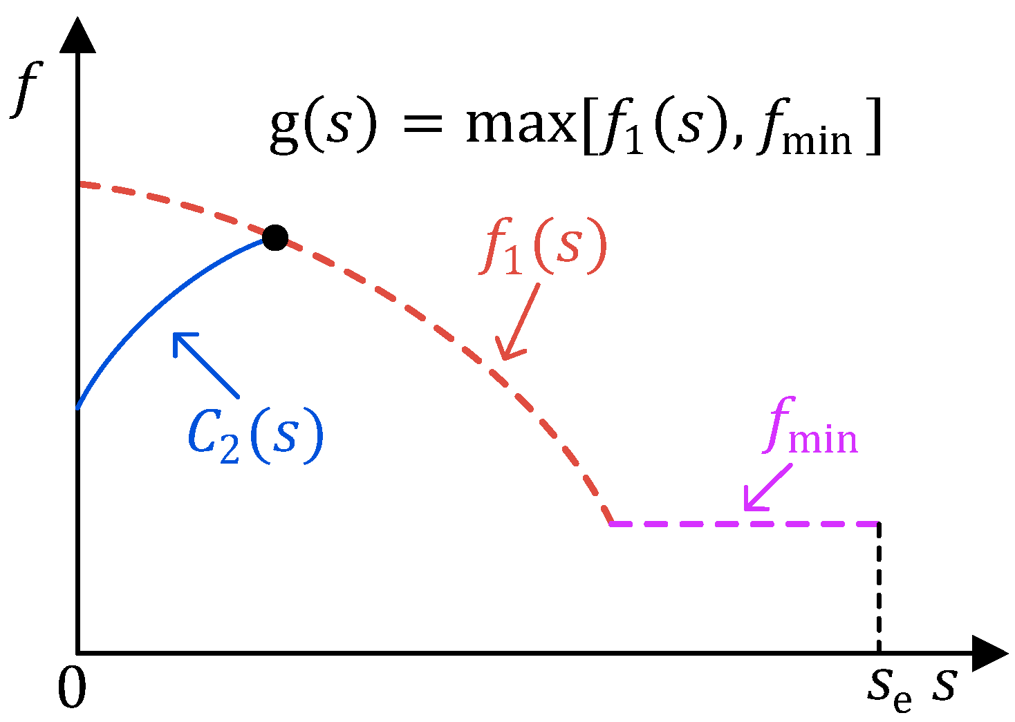
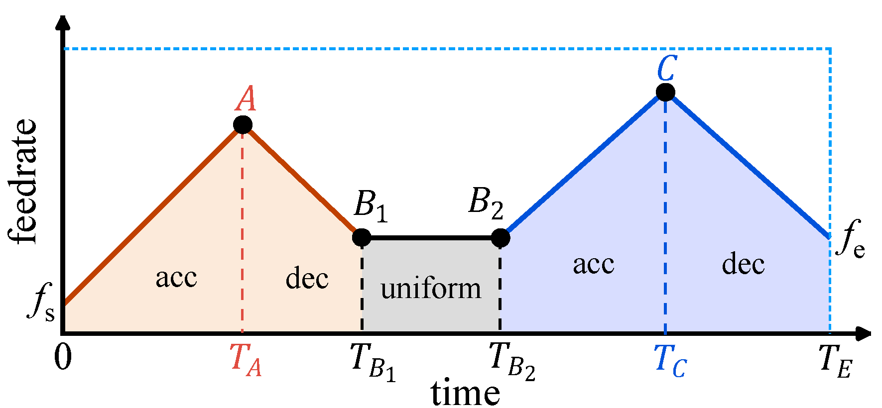
2.3. The Feedrate Planning Method Based on CCC
3. Simulation and Experimental Results
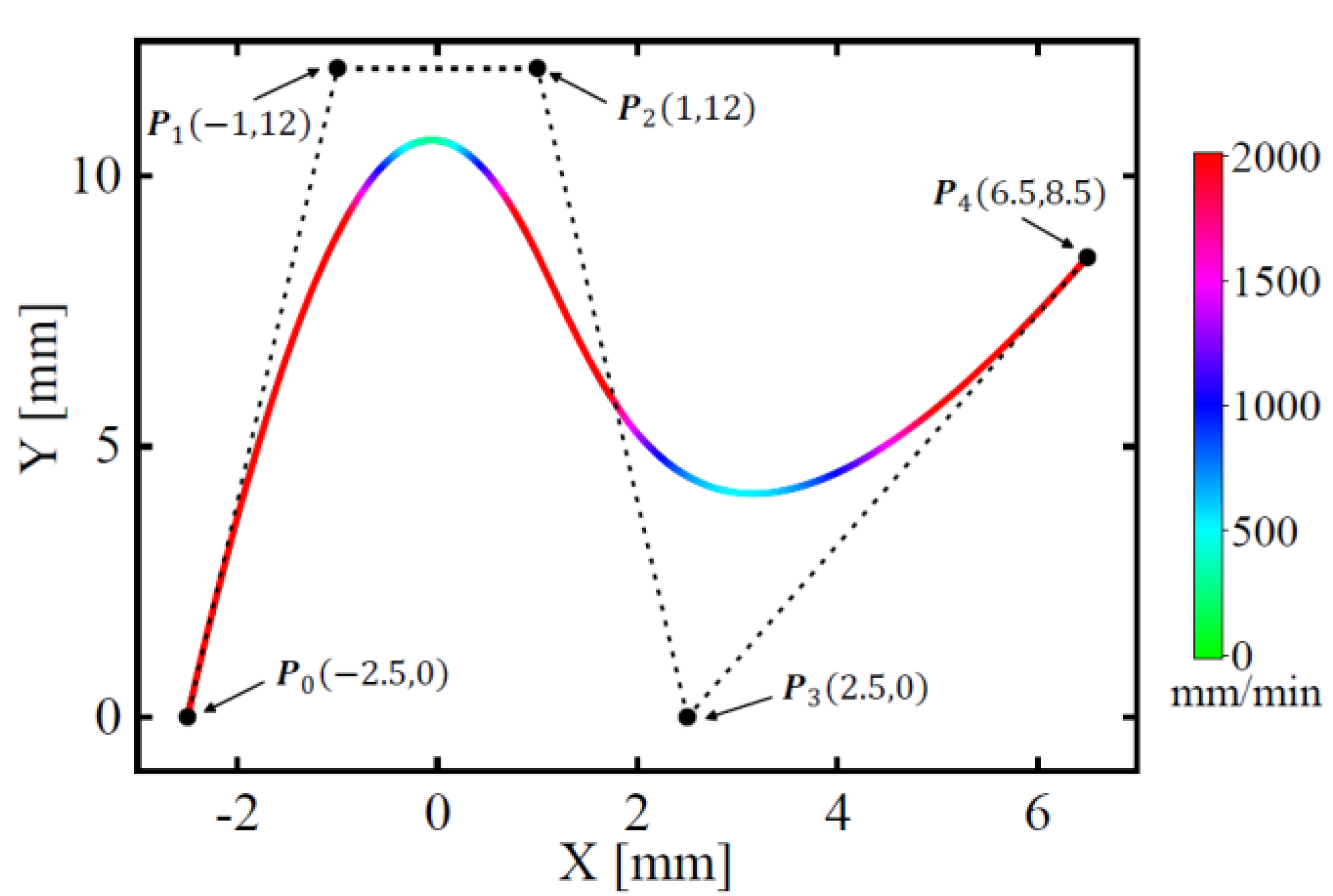
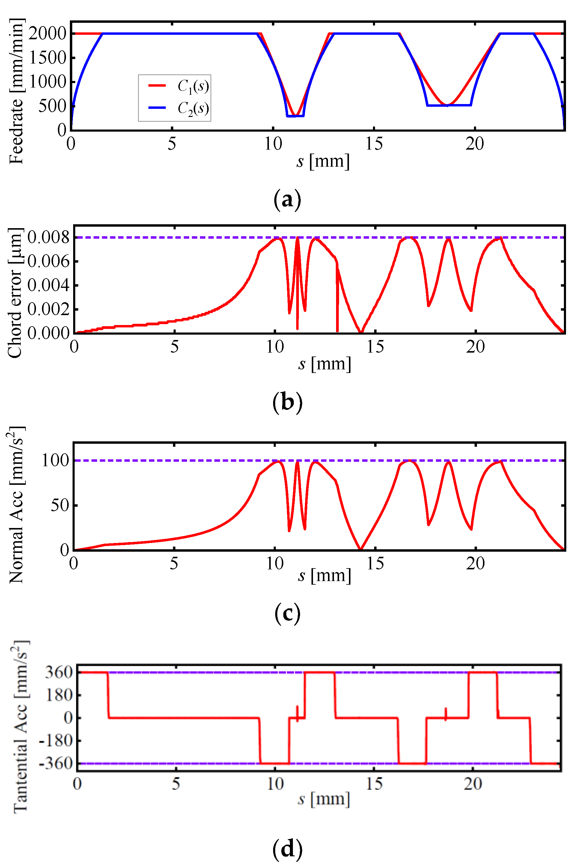
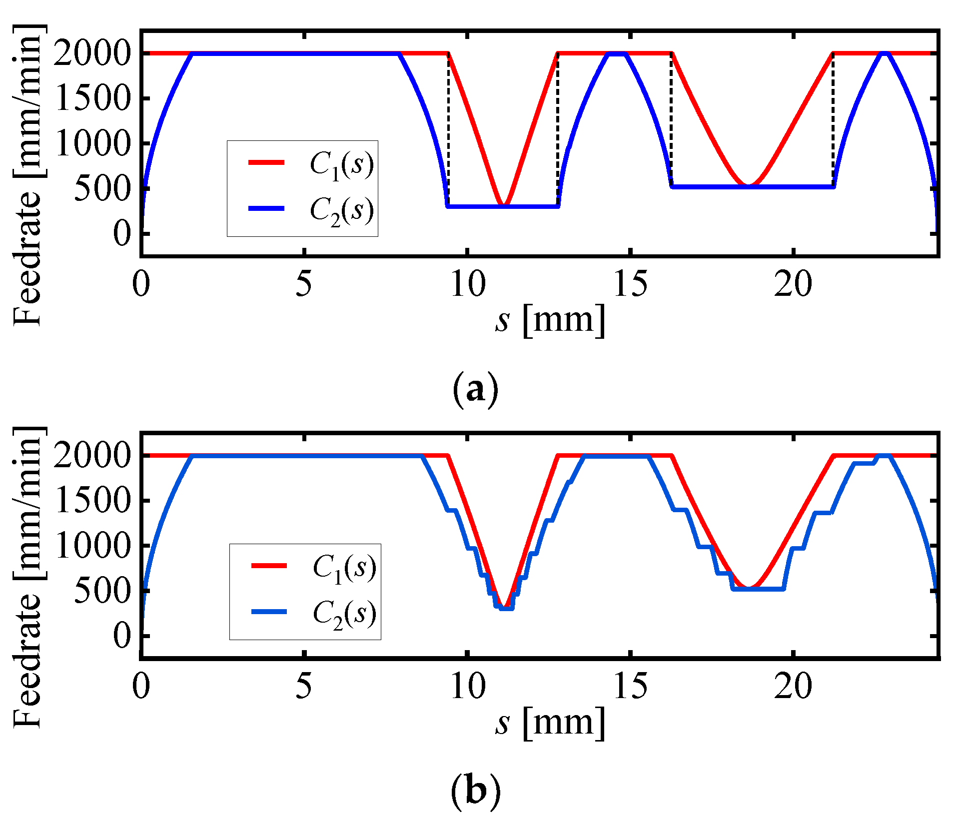
3.1. Simulation
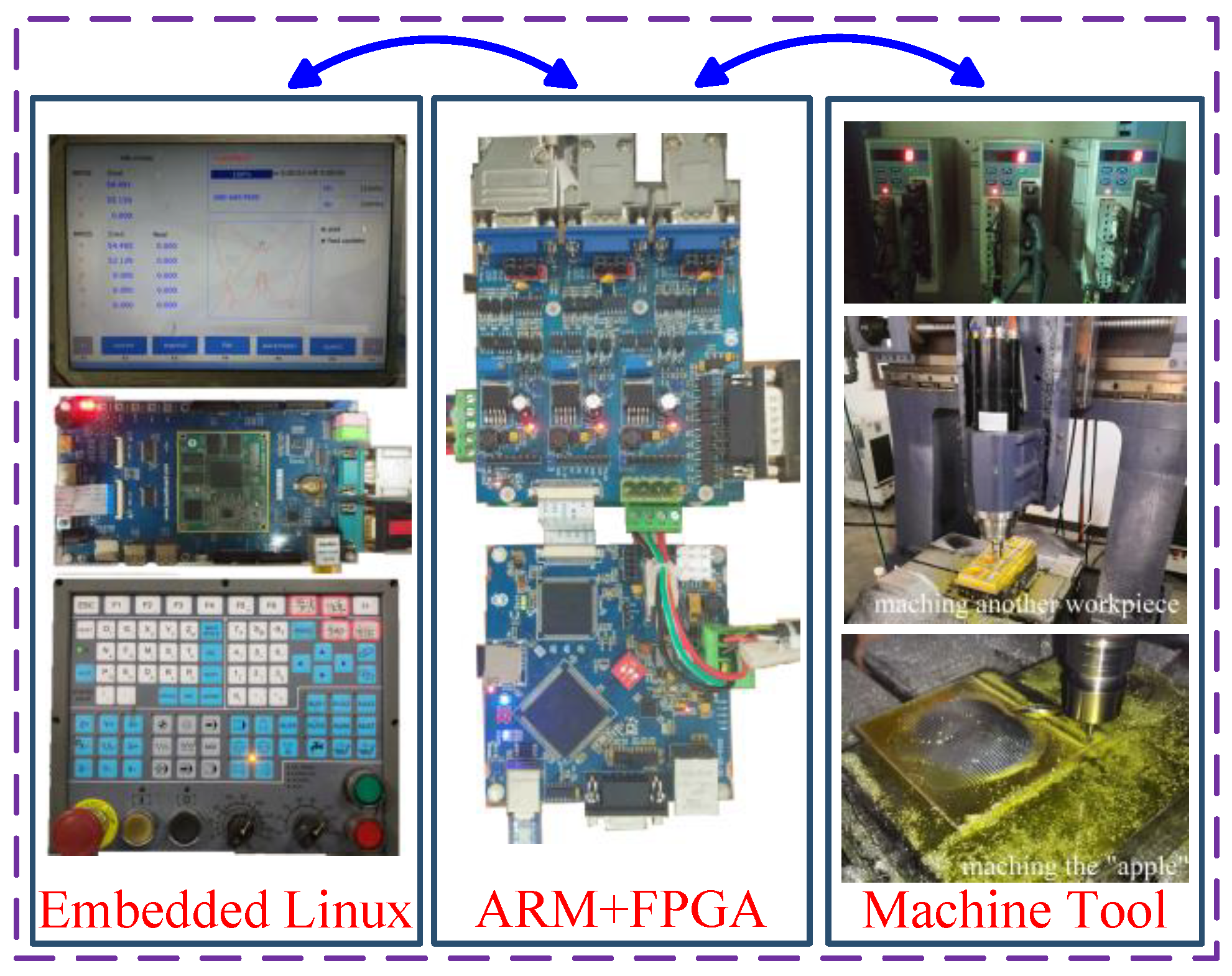
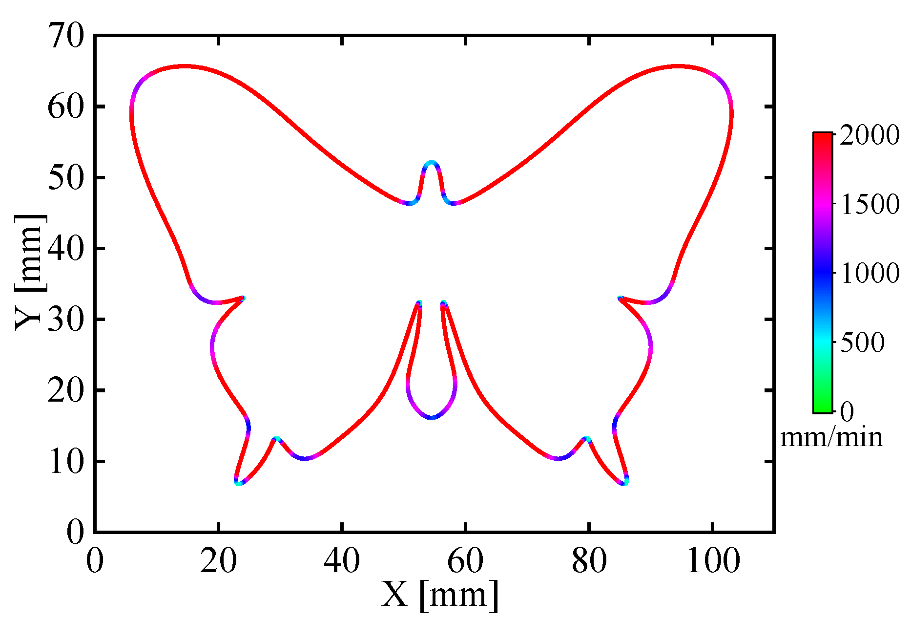
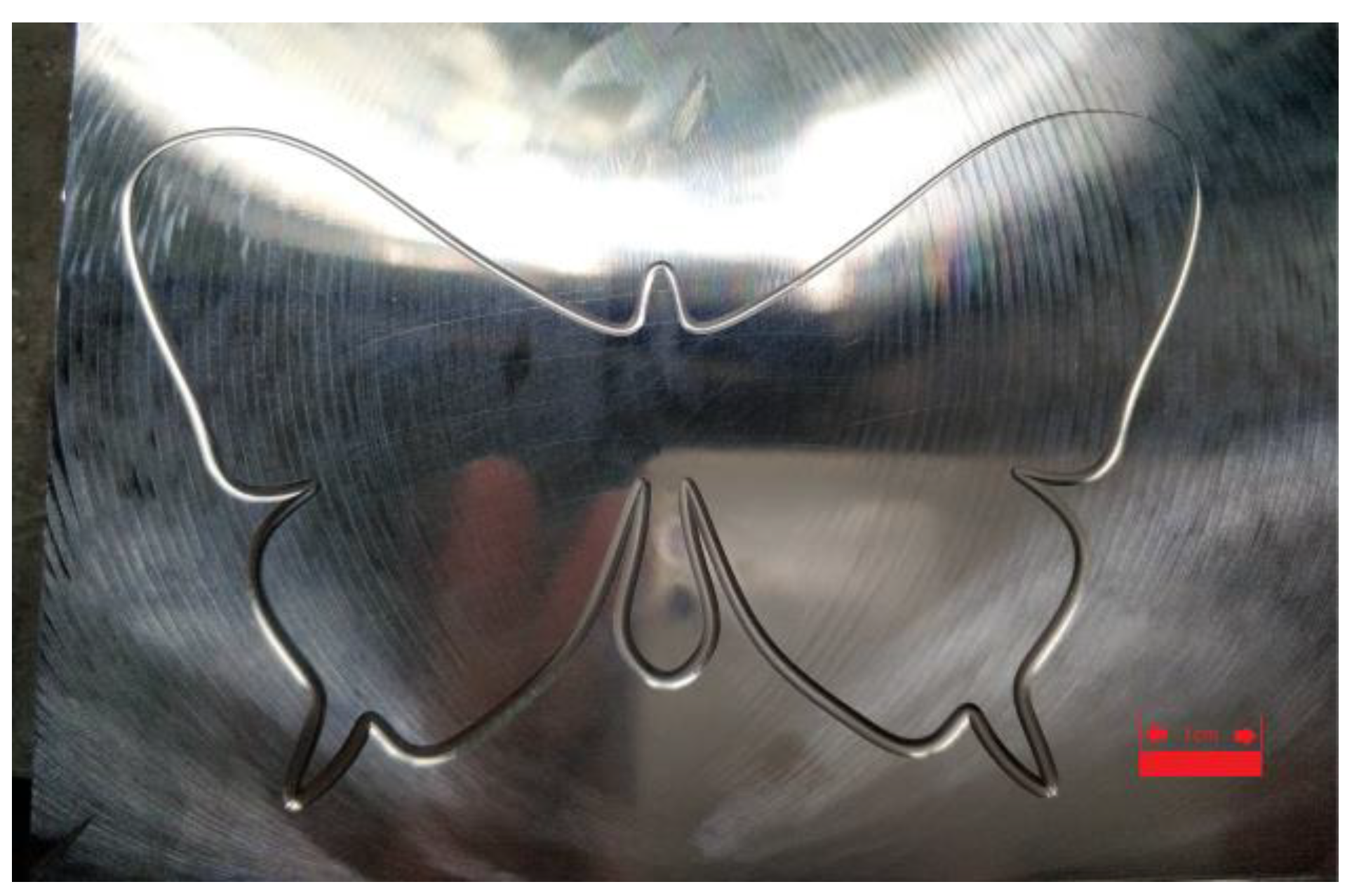
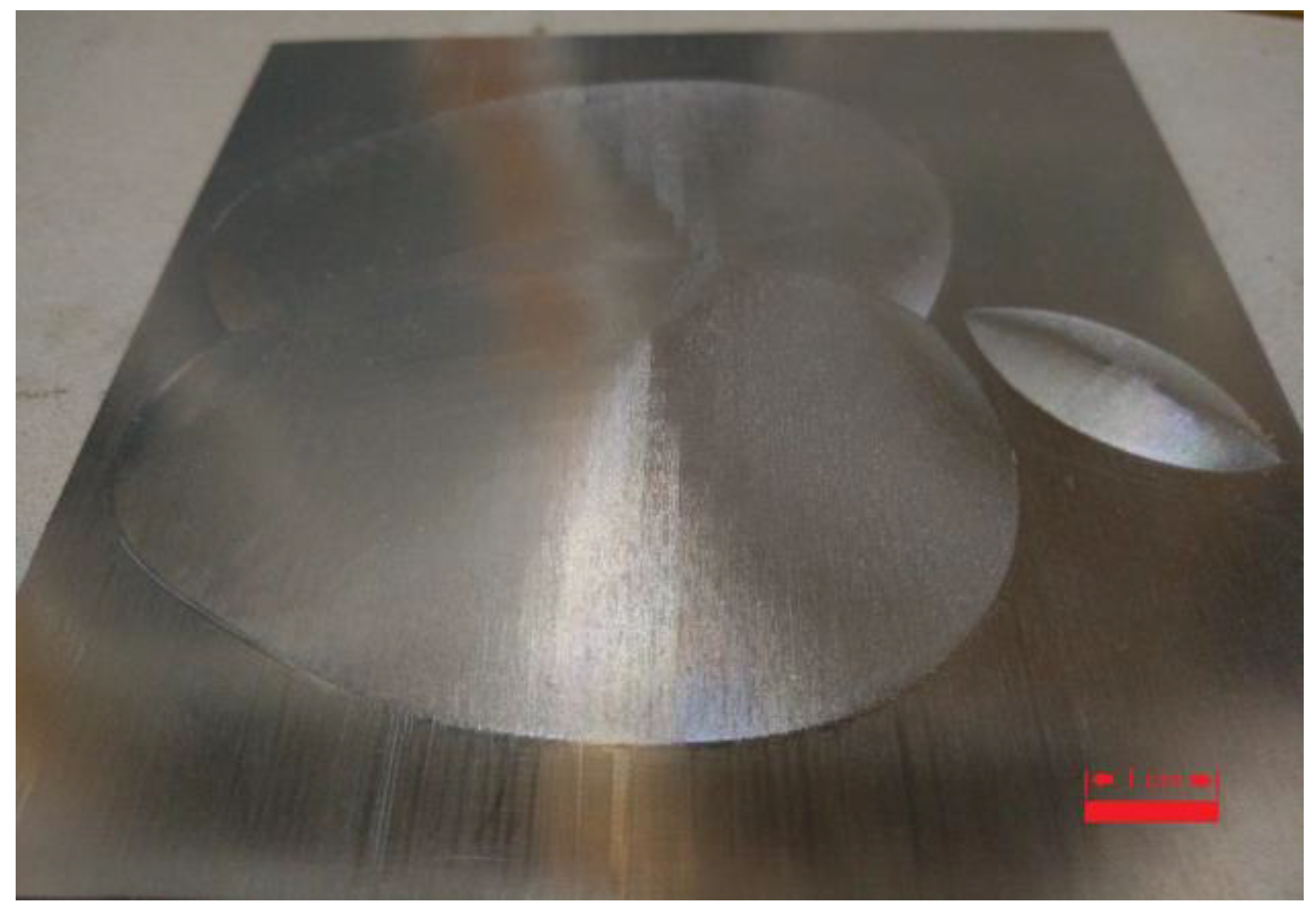
3.2. Experiment
4. Conclusions
Author Contributions
Funding
Institutional Review Board Statement
Informed Consent Statement
Data Availability Statement
Conflicts of Interest
Nomenclature
| NURBS | Non-uniform rational B-splines |
| Acc | Acceleration |
| Dec | Deceleration |
| CCC | A critical constraint curve of the feedrate |
| CCCP | The CCC-based feedrate-planning method |
| A curve with the arc length as the abscissa value and the feedrate-constraint value as the ordinate value | |
| A curve with the arc length as the abscissa value and the feedrate value as the ordinate value | |
| CFTM | A feedrate-planning method base on command-feedrate-threshold dividing + minimum-constraint principle |
| CTM | A feedrate-planning method base on curvature-threshold dividing + minimum-constraint principle |
| Interpolation period, | |
| Radius of curvature, | |
| Chord error, | |
| Normal acceleration, | |
| Tangential acceleration, |
References
- Li, W.; Liu, Y.D.; Yamazaki, K.; Fujisima, M.; Mori, M. The design of a NURBS pre-interpolator for five-axis machining. Int. J. Adv. Manuf. Technol. 2008, 36, 927–935. [Google Scholar] [CrossRef]
- Baek, D.K.; Ko, T.J.; Yang, S.H. Fast and precision NURBS interpolator for CNC systems. Int. J. Precis. Eng. Manuf. 2012, 13, 955–961. [Google Scholar] [CrossRef]
- Jaskolski, P.; Nadolny, K.; Kukielka, K.; Kaplonek, W.; Pimenov, D.Y.; Sharma, S. Dimensional Analysis of Workpieces Machined Using Prototype Machine TooFl Integrating 3D Scanning, Milling and Shaped Grinding. Materials 2020, 13, 5663. [Google Scholar] [CrossRef] [PubMed]
- Tulsyan, S.; Altintas, Y. Local toolpath smoothing for five-axis machine tools. Int. J. Mach. Tools Manuf. 2015, 96, 15–26. [Google Scholar] [CrossRef]
- Wang, Y.S.; Yang, D.S.; Gai, R.L.; Wang, S.H.; Sun, S.J. Design of trigonometric velocity scheduling algorithm based on pre-interpolation and look-ahead interpolation. Int. J. Mach. Tools Manuf. 2015, 96, 94–105. [Google Scholar] [CrossRef]
- Liu, X.H.; Peng, J.Q.; Si, L.; Wang, Z.B. A novel approach for NURBS interpolation through the integration of acc-jerk-continuous-based control method and look-ahead algorithm. Int. J. Adv. Manuf. Technol. 2016, 88, 961–969. [Google Scholar] [CrossRef]
- Wei, J.; Hou, X.D.; Xu, G.P.; Zhang, G.M.; Fan, H.W. Modeling and machining of integral impeller based on NURBS curve. Int. J. Adv. Manuf. Technol. 2021, 113, 2243–2255. [Google Scholar] [CrossRef]
- Jin, Y.; He, Y.; Fu, J.Z. A look-ahead and adaptive speed control algorithm for parametric interpolation. Int. J. Adv. Manuf. Technol. 2013, 69, 2613–2620. [Google Scholar] [CrossRef]
- Liu, Y.; Wan, M.; Qin, X.B.; Xiao, Q.B.; Zhang, W.H. FIR filter-based continuous interpolation of G01 commands with bounded axial and tangential kinematics in industrial five-axis machine tools. Int. J. Mech. Sci. 2020, 169, 105325. [Google Scholar] [CrossRef]
- Jeon, J.W.; Ha, Y.Y. A Generalized Approach for the Acceleration and Deceleration of Industrial Robots and CNC Machine Tools. IEEE Trans. Ind. Electron. 2000, 47, 133–139. [Google Scholar] [CrossRef]
- Altintas, Y. Manufacturing Automation: Metal. Cutting Mechanics, Machine Tool Vibrations, and CNC Design; Zhang, H., Ed.; Chemical Industry Press: Beijing, China, 2002. [Google Scholar]
- Liu, Z.; Dong, J.C.; Ding, Y.Y.; Li, B.; Wang, P. The Study of S-Shaped Acceleration and Deceleration Curve and the Trajectory Planning Strategy Analysis. Key Eng. Mater. 2016, 693, 1195–1199. [Google Scholar] [CrossRef]
- Beudaert, X.; Lavernhe, S.; Tournier, C. Feedrate interpolation with axis jerk constraints on 5-axis NURBS and G1 tool path. Int. J. Mach. Tools Manuf. 2012, 57, 73–82. [Google Scholar] [CrossRef]
- Jin, Y.; He, Y.; Fu, J.Z.; Lin, Z.W.; Gan, W.F. A fine-interpolation-based parametric interpolation method with a novel real-time look-ahead algorithm. Comput. Aided Des. 2014, 55, 37–48. [Google Scholar] [CrossRef]
- Yang, M.; Zhao, X.C.; Zhong, Z.; Yue, Y.; Gao, P.; Li, Q. Adaptive Velocity Planning under Complex Constraints for 5-axis CNC Systems. Chin. J. Mech. Eng. 2020, 56, 161–171. [Google Scholar] [CrossRef]
- Erkorkmaz, K.; Chen, Q.G.; Zhao, M.Y.; Beudaert, X.; Gao, X.S. Linear programming and windowing based feedrate optimization for spline toolpaths. CIRP Ann. 2017, 66, 393–396. [Google Scholar] [CrossRef]
- Sun, Y.W.; Zhao, Y.; Bao, Y.R.; Guo, D.M. A novel adaptive-feedrate interpolation method for NURBS tool path with drive constraints. Int. J. Mach. Tools Manuf. 2014, 77, 74–81. [Google Scholar] [CrossRef]
- Du, X.; Huang, J.; Zhu, L.M. A complete S-shape feed rate scheduling approach for NURBS interpolator. J. Comput. Des. Eng. 2015, 2, 206–217. [Google Scholar] [CrossRef]
- Jia, Z.Y.; Song, D.N.; Ma, J.W.; Hu, G.Q.; Su, W.W. A NURBS interpolator with constant speed at feedrate-sensitive regions under drive and contour-error constraints. Int. J. Mach. Tools Manuf. 2017, 116, 1–17. [Google Scholar] [CrossRef]
- Bardine, A.; Campanelli, S.; Foglia, P.; Prete, C.A. NURBS Interpolator with Confined Chord Error and Tangential and Centripetal Acceleration Control. In Proceedings of the IEEE 2010 International Congress on Ultra Modern Telecommunications & Control Systems & Workshops (ICUMT), Moscow, Russia, 18–20 October 2010; pp. 489–496. [Google Scholar]
- Annoni, M.; Bardine, A.; Campanelli, S.; Foglia, P.; Prete, C.A. A real-time configurable NURBS interpolator with bounded acceleration, jerk and chord error. Comput. Aided Des. 2012, 44, 509–521. [Google Scholar] [CrossRef]
- Piegl, L.A.; Tiller, W. The NURBS Book, 2nd ed.; Springer: Berlin/Heidelberg, Germany, 1997. [Google Scholar]
- Lai, J.Y.; Lin, K.Y.; Tseng, S.J.; Ueng, W.D. On the development of a parametric interpolator with confined chord error, feedrate, acceleration and jerk. Int. J. Adv. Manuf. Technol. 2007, 37, 104–121. [Google Scholar] [CrossRef]
- Lin, M.T.; Tsai, M.S.; Yau, H.T. Development of a dynamics-based NURBS interpolator with real-time look-ahead algorithm. Int. J. Mach. Tools Manuf. 2007, 47, 2246–2262. [Google Scholar] [CrossRef]
- Yeh, S.S.; Hsu, P.L. Adaptive-feedrate interpolation for parametric curves with a confined chord error. Comput. Aided Des. 2002, 34, 229–237. [Google Scholar] [CrossRef]
- Liang, H.B.; Wang, Y.Z.; Li, X. Research and implementation of NURBS interpolation algorithm for adaptive feed speed. Comput. Integr. Manuf. Syst. 2006, 12, 428–433. [Google Scholar] [CrossRef]
- Wang, G.Z.; Liang, H.B. An Acceleration-Deceleration Control Method of NURBS Curve with Real-Time Look-Ahead Function. Mach. Des. Manuf. 2016, 110, 103–106. [Google Scholar] [CrossRef]
- Xu, R.Z.; Xie, L.; Li, C.X.; Du, D.S. Adaptive parametric interpolation scheme with limited acceleration and jerk values for NC machining. Int. J. Adv. Manuf. Technol. 2006, 36, 343–354. [Google Scholar] [CrossRef]
- Wu, J.C.; Zhou, H.C.; Tang, X.Q.; Chen, J.H. A NURBS interpolation algorithm with continuous feedrate. Int. J. Adv. Manuf. Technol. 2011, 59, 623–632. [Google Scholar] [CrossRef]
- Chen, Y.D.; Ji, X.S.; Tao, Y.; Wei, H.X. Look-Ahead Algorithm with Whole S-Curve Acceleration and Deceleration. Adv. Mech. Eng. 2013, 5, 974152. [Google Scholar] [CrossRef]
- Huang, J.; Du, X.; Zhu, L.M. Feasibility of the Bi-Directional Scanning Method in Acceleration/deceleration Feedrate Scheduling for CNC Machining. In Proceedings of the 10th International Conference Intelligent Robotics and Applications (ICIRA), Wuhan, China, 16–18 August 2017; pp. 171–183. [Google Scholar]
- Obukhov, A.I.; Martinova, L.I.; Lyubimov, A.B. Developing of the Look Ahead Algorithm for Linear and Nonlinear Laws of Control of Feedrate in CNC. Autom. Remote Control 2020, 81, 380–386. [Google Scholar] [CrossRef]


| Symbol | Parameter | Value |
|---|---|---|
| Interpolation period | ||
| Chord error | ||
| Normal acceleration | ||
| Tangential acceleration | ||
| Command feedrate | ||
| Speed of the electric spindle |
| Planning Method | Number of Sub-Curves | Machining Time (s) | Acc/Dec Time (s) |
|---|---|---|---|
| 2 | 1.04 | 0 | |
| CFTM | 6 | 1.94 | 0.90 |
| Command feedrate threshold dividing + CCCP | 6 | 1.26 | 0.22 |
| CTM | 23 | 1.29 | 0.25 |
| Curvature threshold dividing + CCCP | 23 | 1.18 | 0.14 |
| Planning Method | Number of Sub-Curves | Machining Time (s) | Acc/Dec Time (s) |
|---|---|---|---|
| 48 | 13.93 | 0 | |
| CFTM | 89 | 19.03 | 5.10 |
| Command feedrate threshold dividing + CCCP | 89 | 15.20 | 1.27 |
| CTM | 207 | 15.62 | 1.69 |
| Curvature threshold dividing + CCCP | 207 | 14.91 | 0.98 |
Publisher’s Note: MDPI stays neutral with regard to jurisdictional claims in published maps and institutional affiliations. |
© 2021 by the authors. Licensee MDPI, Basel, Switzerland. This article is an open access article distributed under the terms and conditions of the Creative Commons Attribution (CC BY) license (https://creativecommons.org/licenses/by/4.0/).
Share and Cite
Guo, P.; Wu, Y.; Yang, G.; Shen, Z.; Zhang, H.; Zhang, P.; Lou, F.; Li, H. A Feedrate Planning Method for the NURBS Curve in CNC Machining Based on the Critical Constraint Curve. Appl. Sci. 2021, 11, 4959. https://doi.org/10.3390/app11114959
Guo P, Wu Y, Yang G, Shen Z, Zhang H, Zhang P, Lou F, Li H. A Feedrate Planning Method for the NURBS Curve in CNC Machining Based on the Critical Constraint Curve. Applied Sciences. 2021; 11(11):4959. https://doi.org/10.3390/app11114959
Chicago/Turabian StyleGuo, Peng, Yijie Wu, Guang Yang, Zhebin Shen, Haorong Zhang, Peng Zhang, Fei Lou, and Hengbo Li. 2021. "A Feedrate Planning Method for the NURBS Curve in CNC Machining Based on the Critical Constraint Curve" Applied Sciences 11, no. 11: 4959. https://doi.org/10.3390/app11114959
APA StyleGuo, P., Wu, Y., Yang, G., Shen, Z., Zhang, H., Zhang, P., Lou, F., & Li, H. (2021). A Feedrate Planning Method for the NURBS Curve in CNC Machining Based on the Critical Constraint Curve. Applied Sciences, 11(11), 4959. https://doi.org/10.3390/app11114959