Article

Impacts of Traverse Speed and Material Thickness on Abrasive Waterjet Contour Cutting of Austenitic Stainless Steel AISI 304L

School of Engineering, Edith Cowan University, Joondalup, WA 6027, Australia
*
Author to whom correspondence should be addressed.
Appl. Sci. 2021, 11(11), 4925; https://doi.org/10.3390/app11114925
Submission received: 6 May 2021 / Revised: 16 May 2021 / Accepted: 25 May 2021 / Published: 27 May 2021
(This article belongs to the Special Issue Advanced Manufacturing of Metals)

Abstract

:
Abrasive water jet machining is a proficient alternative for cutting difficult-to-machine materials with complex geometries, such as austenitic stainless steel 304L (AISI304L). However, due to differences in machining responses for varied material conditions, the abrasive waterjet machining experiences challenges including kerf geometric inaccuracy and low material removal rate. In this study, an abrasive waterjet machining is employed to perform contour cutting of different profiles to investigate the impacts of traverse speed and material thickness in achieving lower kerf taper angle and higher material removal rate. Based on experimental investigation, a trend of decreasing the level of traverse speed and material thickness that results in minimum kerf taper angle values of 0.825° for machining curvature profile and 0.916° for line profiles has been observed. In addition, higher traverse speed and material thickness achieved higher material removal rate in cutting different curvature radii and lengths in line profiles with obtained values of 769.50 mm3/min and 751.5 mm3/min, accordingly. The analysis of variance revealed that material thickness had a significant impact on kerf taper angle and material removal rate, contributing within the range of 69–91% and 62–69%, respectively. In contrast, traverse speed was the least factor measuring within the range of 5–18% for kerf taper angle and 27–36% for material removal rate.

1. Introduction

Austenitic stainless steel 304L (AISI 304L) possesses excellent forming and welding characteristics, which has led to its broad application in industries such as automotive, shipbuilding and marine, material handling equipment, automotive parts, as well as construction materials [1]. AISI 304L is widely used in various thickness in the fabrication industry and in many cases requires contour machining to achieve complex and complicated profiles. However, AISI 304L is a difficult-to-cut material due to its high alloying content (i.e., chromium and nickel), low thermal conductivity, high ductility, and low machinability level [1]. Therefore, when cutting AISI 304L, it can be challenging to choose an alternative to achieve precise cutting without compromising metallurgical properties. Although various non-conventional technologies have been applied to cut stainless steel, such as a laser beam machines; this technology often has a high thermal distortion that alters metallurgical properties of the workpiece [2]. Abrasive waterjet machining (AWJM) is one of these advanced technologies that has been a popular method for cutting metallic and heat-sensitive materials due to several advantages, such as the absence of heat-affected zone (HAZ) and no changes in material properties [3]. AWJM can cut both hard and delicate materials with a wide range of thicknesses with a very low machining force, preventing the destruction of the properties of the target workpiece [4]. Moreover, whilst AWJM is also considered environmentally friendly and sustainable as it does not omit any hazardous vapours; hence, AWJM produces waste abrasives that affect the environment. Accordingly, recycling or reusing of these abrasives has the potential to resolve ecological issues and concerns relating to AWJ application [5,6,7].
Abrasive waterjet machining is comprised of several input process parameters that ultimately determine the efficiency and quality of the machining processes. These parameters are generally categorised as hydraulic, abrasives, cutting and mixing, and acceleration [8]. Whilst AWJM demonstrates capability in cutting difficult-to-machine materials, they still experience some challenges. There have been reported issues in material response to AWJM concerning its behaviour, such as kerf tapering and low material removal, since the beginning of its applications. Kerf taper is the tapering angle generated during the AWJM process associated with the variation of kerf widths, which involves cut width of the material at the top and bottom [9,10]. Further, materials like AISI 304L have a relatively low material removal rate due to their relative machinability. The material removal rate in an AWJM for ductile materials like stainless steel is facilitated by a combination of cutting wear and deformation wear mechanism [9]. This involves determining the quantity of removed material from the workpiece per unit time, where the literature reveals that varied studies have been conducted on the effects of different parameters on the quality and efficiency of abrasive waterjet cutting performance. Therefore, an appropriate combination of AWJM input parameters, such as waterjet pressure, traverse speed, and mass rate of abrasive particles is important to achieve the required machining efficiency and material surface qualities [3]. For instance, Miao, et al. [11] studied quality defects such as kerf taper, cutting residue, and striation in AWJ cutting of AISI 304. Their study postulated that decreasing the jet energy is the cause of quality defects. Mohamad et al. [12] investigated the kerf taper angle generated in AWJ cutting of AISI 1090 mild steel with results indicating that the ratio of kerf taper increases at a higher level of standoff distance. They established that abrasive particles have higher kinetic energy at higher standoff distance leading to wider kerf taper angles; moreover, these particles gradually lose their kinetic energy as it moves towards from jet entry up to the exit. Kavya et al. [13] reported that the most influential parameters for MRR in AWJM of Al7075-TiB2 were traverse speed and abrasive mass flow rate. In their study, traverse speed is the most influential factor in achieving higher volumetric MRR. Ishfaq et al. [14] studied how traverse speed and abrasive mass flow rate are significant parameters for material removal rate, where traverse speed is considered the most influencing factor on AWJM of stainless-clad steel workpieces. Babu et al. [15] concluded that a slower feed rate allows more abrasives to strike the material and its jet does not drop much of its energy during the machining process, resulting in a lower kerf taper angle and surface roughness on abrasive waterjet cutting of AISI 1018 with 5 mm thickness. Thakkar et al. [16] investigated the effect of traverse speed, abrasive mass flow rate, and standoff distance on material removal rate in abrasive waterjet cutting of mild steel. Their experimental results showed that a higher traverse speed and abrasive mass flow rate increased the material removal rate. Moreover, a higher traverse speed has been shown to decrease kerf taper in AWJM straight line of AISI 304 [17]. Traverse speed regulates the quality of cut surfaces generated by AWJM applications, measured in mm/min [
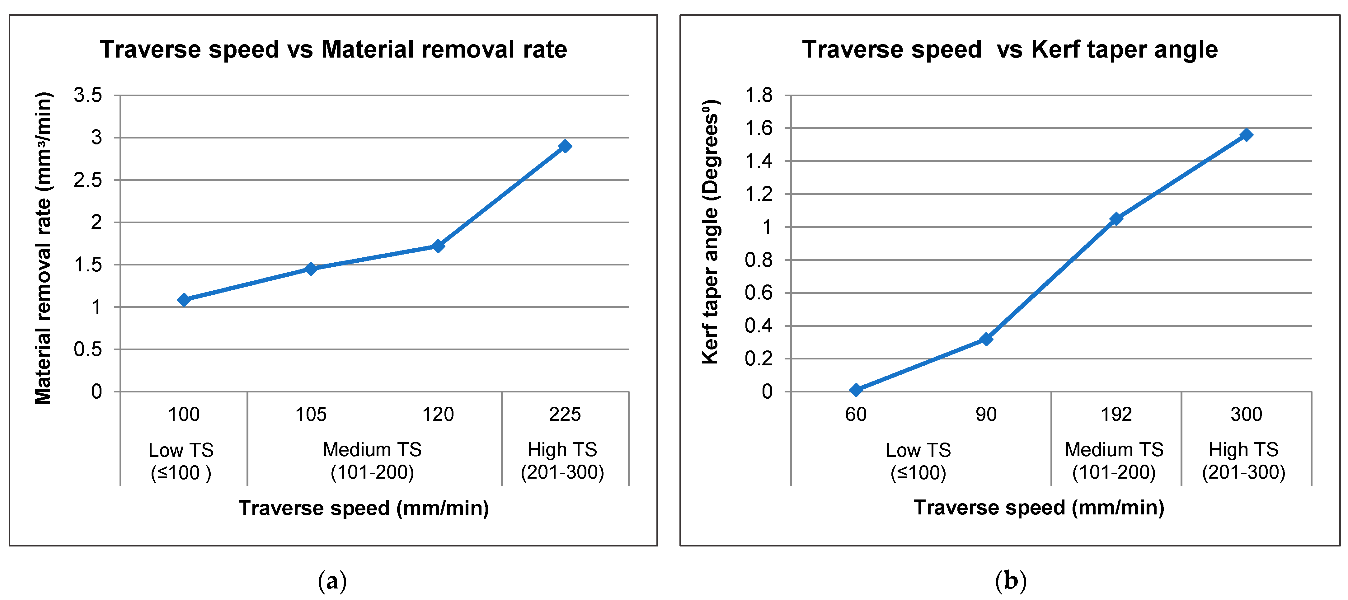
3]. Challenges of material reactions to AWJM have been investigated since the inception of this technique, where they continue to be studied, with regards to performance, including low material removal rate and distorted kerf geometries when employing varied traverse speed levels. A summary of experimental results obtained from several reviewed studies that investigated the impact of traverse speed on MRR and KTA in different metals in AWJM i.e., TRIP steel sheets, AISI 304, AISI 1018 and Inconel 600 is given in Figure 1 [8,15,18,19,20,21,22].
It is evident from Figure 1 that a lower kerf taper angle can be attained by utilising a lower traverse speed, whereas a higher rate of material removal can be obtained by increasing traverse speed. Accordingly, traverse speed is directly proportional to the material removal rate but inversely proportional to kerf taper [23]. Previous studies have applied specific material thicknesses in their AWJM experiments. However, in stainless steel fabrication industries, cutting involves different thicknesses for product formation, where it is necessary to investigate the influence of material thickness in precise AWJ cutting. Khan et al. [22] conducted machinability study in cutting low alloy steel of different thicknesses (5, 10, 15, 20 mm). Their experiments reported that material thickness impacts machine performance, including aspects of material removal rate, surface roughness, and kerf wall inclination. Further, their study showed that increasing the thickness of the material requires a higher traverse speed and water jet pressure in order to achieve better results. Additionally, Kechagias et al. [8] investigated the influence of sheet thickness, nozzle diameter, standoff distance, and traverse speed to kerf geometry and surface roughness in AWJM of transformation-induced plasticity (TRIP) sheet steel with varied thickness of 0.9 and 1.25 mm. They concluded that for higher thickness material, decreased kerf width and roughness can be achieved by applying a low standoff distance, a lower rate of traverse speed, and by using a smaller nozzle diameter. This could be due to the combination of high-level standoff distance and high rate traverse speed that effectively lower the contact time of abrasive particles within the cutting process.
The literature to date indicates that AWJM experiments and studies have been used specifically in relation to cutting straight line profiles, with only limited investigations regarding the machining of complicated shapes, such as curves with differing radii. Further, the cutting of complex geometries is more frequently applied in manufacturing industries than straight-slit or linear cutting [24]. Due to the taper and deceleration of a jet inside the kerf, challenges such as deformation of the material during the machining process can arise, particularly when cutting corners and curvature [25]. Therefore, this research gap requires further investigation.
AWJM is extensively used in the metal fabrication industry due to its capability to generate contours. This technology can produce contours due to their unidirectional cutting path system [26]. In addition, contour cutting is much more commonly applied rather than straight-slit cutting for metal product formation. Contour cutting involves various convex and concave arcs that make the process more challenging when compared to linear cutting. To achieve precision in contour cutting, proper management of the process parameters are essential. In this research, austenitic stainless steel grade 304L material is utilised to examine the performance of abrasive waterjet contour-cutting. Key variables, such as material thickness and traverse speed, were considered in addressing issues relating to the differing radii of curvature, acute edges, and straight cutting path of AWJM.

2. Materials and Methods

In this work, AISI 304L was investigated. Austenitic stainless steel grades, such as 304L, are characterised as the most corrosion-resistant among other steel grades with high formability, ductility, and weldability because they contain a high percentage of chromium and nickel content [1]. This is the reason behind gaining higher volumes in a variety of manufacturing settings. This rising market demand has led to further studies aimed at achieving greater efficiency in the quality of cut during the machining process of abrasive watejet.
The chemical composition and mechanical properties of AISI 304L are detailed in Table 1. The material thicknesses applied within this study were 4, 8, and 12 mm, with a uniform gap to observe the relative differences in AWJM behaviour towards this material. This experiment was conducted on an abrasive waterjet contour-cutting operation to investigate the impacts of traverse speed.
An abrasive waterjet machine, model OMAX MAXIEM 1515, was used for contour cutting of the AISI 304L material. The machine has a built-in PC-based CAD/CAM with many distinct programming features including: adjustment of cutting model; six levels of quality; estimating the time needed for machining; generating data and reports; forming and tracking several sites, and rotating, ascending, reversing, and counterpoising. The specifications of the machine are further detailed in 
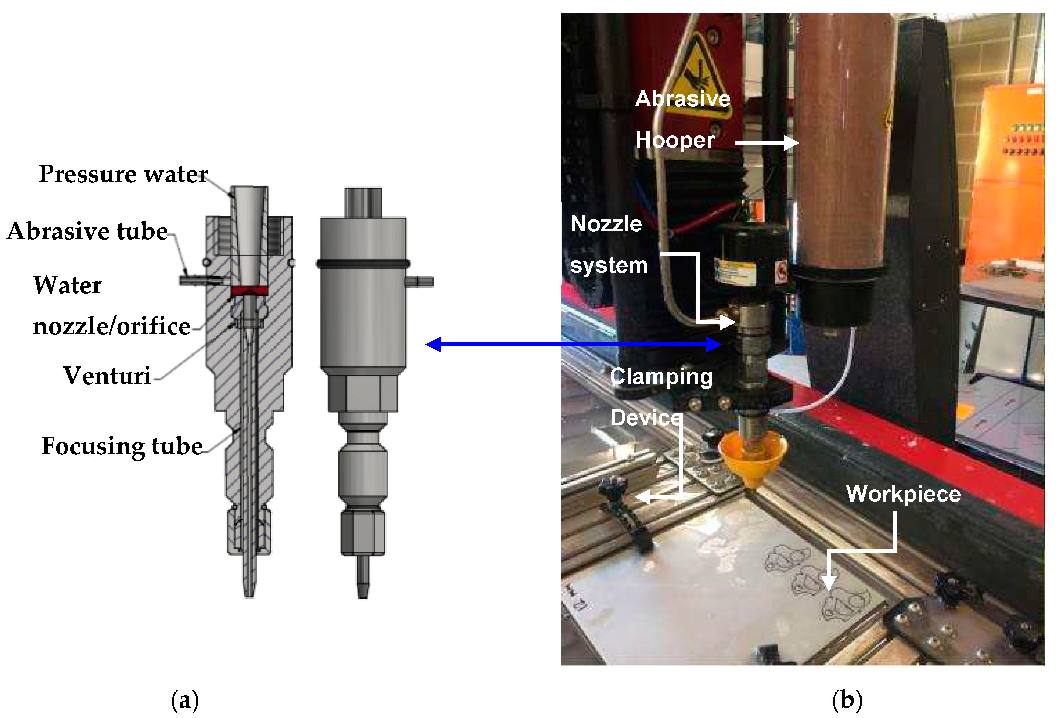
Table 2 and the corresponding set-up for experiments is illustrated in Figure 2 [23].
As presented in Figure 2a, the abrasive waterjet machine generates high-pressure water from the pump machine, which is then driven to the nozzle system. The nozzle system includes an abrasive hopper, an orifice, a mixing chamber, and a focusing tube. The water, travelling with a high level of velocity, is forced out of the orifice in a very thin stream structure [27]. The hopper consists of a plastic tube holding the abrasive particles and dispensing them to the cutting head, where the abrasive particles are drawn into a waterjet stream in the mixing chamber. The high-speed waterjet together with the abrasive particles are then mixed and accelerated to create an abrasive waterjet [27].
The workpiece is secured in a clamping tool to hold it in position during machining, as shown in Figure 2b. This is done to preclude the possibility of deflection during cutting as the abrasive loaded stream meets the surface of the workpiece. Additionally, the stable plane of the workpiece material is fixed so that the kerf profile is not disrupted.
The cutting path used in this study is illustrated in Table 3. According to Wang et al. [28], a specified length of straight cut profile ranging from 10 to 40 mm is sufficient to achieve a stable phase of traverse speed covering the acceleration and deceleration phase. Therefore, the selected curves and arcs profile, i.e., 10–40 mm, provided evidence of high kerf taper and geometrical inaccuracies from previous investigations [28,29,30,31], demonstrating the need for further analyses using hard-to-cut materials.
The input parameters selected in this study were traverse speed and material thickness, while waterjet pressure, abrasive mass flow rate, standoff distance, abrasive type, and mesh number were held constant. Three levels of material thickness and traverse speed were applied, as shown in Table 4. The selection of variable parameters, and the assignment of levels, was made following an intensive review of current research data. Input parameter settings were constantly redefined, due to limitations with the machine and/or constraints in effectiveness shown in previous AWJM experiments [8,15,18,19,20,21,22]. The input parameters that were kept constant during the tests are shown in Table 5.
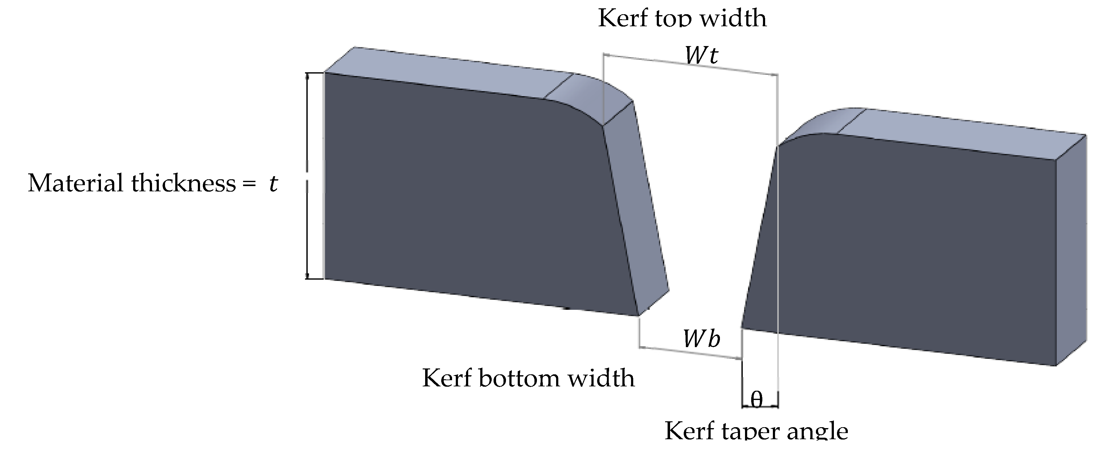
The performance of AWJM is determined by the amount of material removed from the target workpiece and by the accuracy of the geometry of the cut relying on the kerf width and taper angle [32]. Therefore, the kerf taper angle and material removal rate have been selected for consideration as output parameters in this study. Kerf taper angle resulting from abrasive waterjet contour cutting is measured according to the proportion of the sum of kerf top width and kerf bottom and thickness of the workpiece [
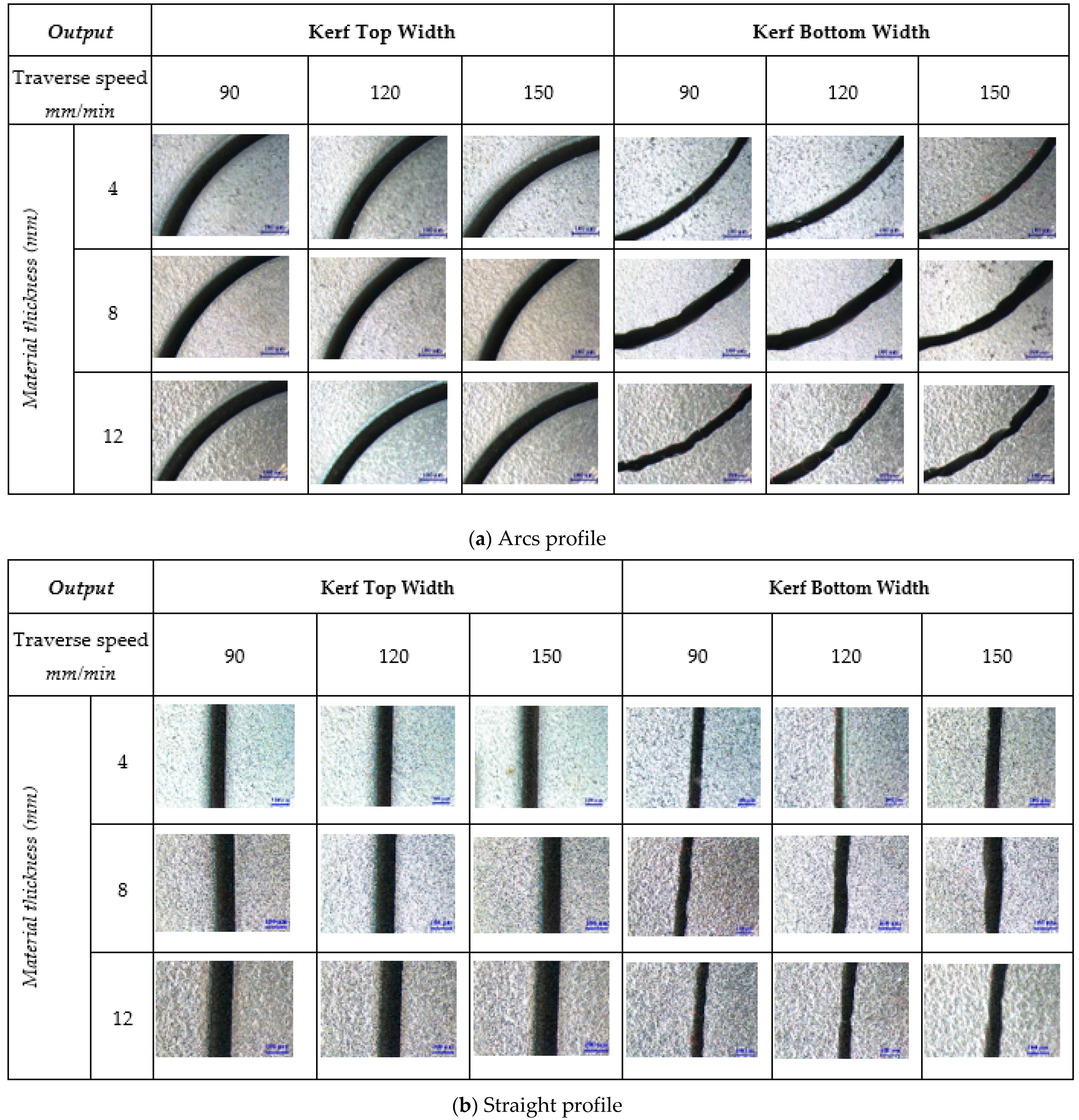
10]. Kerf width refers to the ratio of entry and exit cut width. Kerf width dimensions are measured on the top as well as bottom by using an optical microscope, model LEICA M80, with a precision scale of 100 µm. Equation (1) was utilised to calculate the kerf taper angle following abrasive waterjet cutting of AISI 304L [33]. A scheme of the applied kerf geometries is illustrated in Figure 3 [14].
K e r f   T a p e r   A n g l e   θ = A r c t a n W t W b 2 t
The material removal rate, which is the volume of material removed from the material per unit of time, is measured by kerf width, traverse speed, and depth of cut. The material removal rate was calculated using Equation (2) [32]:
M R R = h t · W · V f
wherein: W = W t + W b 2
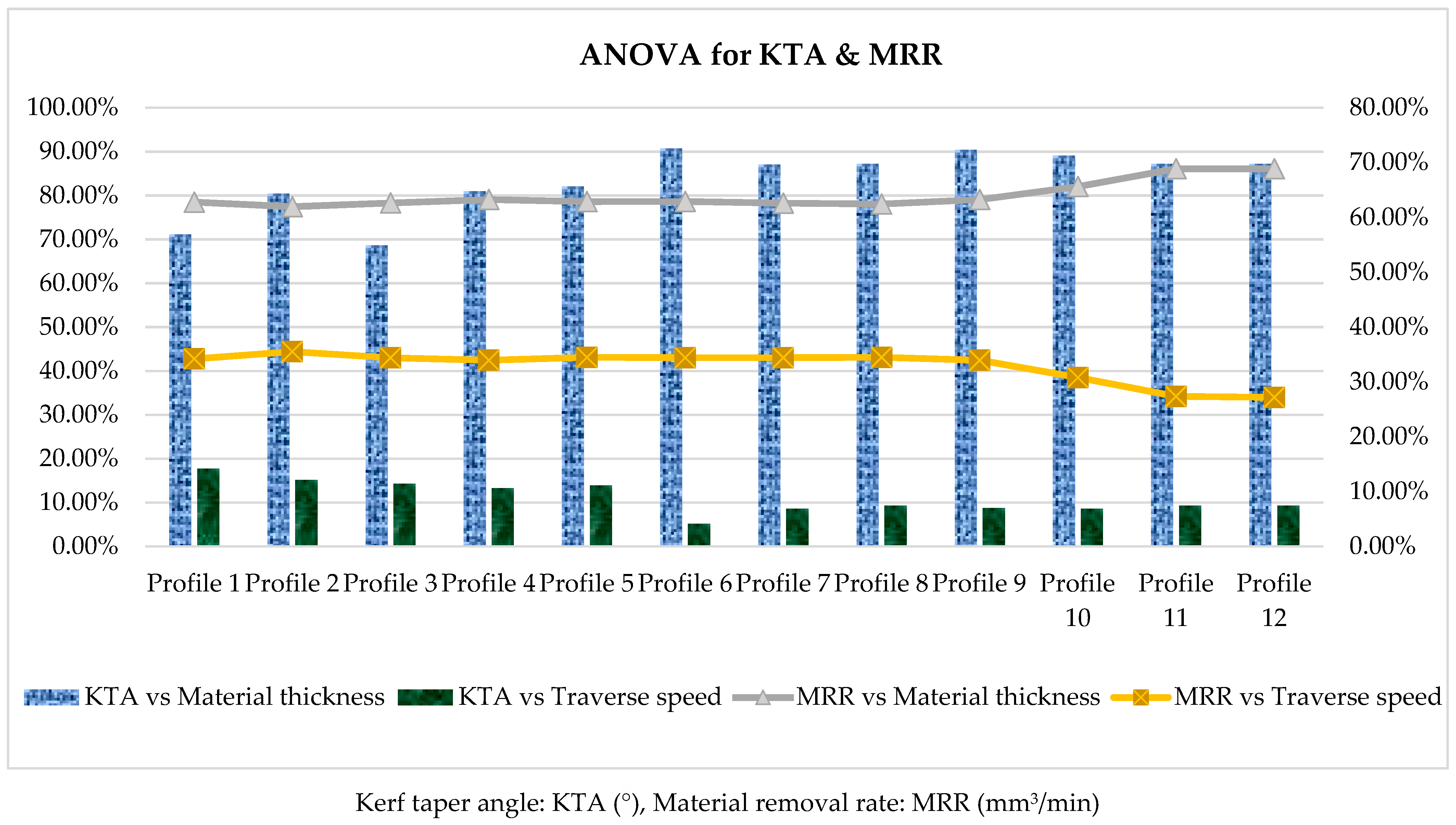
Finally, analysis of variance (ANOVA) was applied to quantify the influence of the selected variable parameters. The ANOVA was employed to identify the significant effect of input parameters and their corresponding levels [34]. ANOVA was performed with a confidence interval of 95%, which has typically been applied in several related studies. The confidence interval determines how precise the estimated statistics are, whereby a 95% confidence interval denotes a 5% chance of having an incorrect estimation [35,36]. The percentage contribution assesses the effect of each input parameter on the output, where p-values estimated at more than 0.05 or 5%, are considered insignificant [37].

3. Results and Discussion

3.1. Kerf Top Width and Bottom Results

Figure 4 shows microscopic observations of AISI 304L with a thickness of 4, 8, and 12 mm at traverse speeds of 90, 120, and 150 mm/min, where kerf geometries such as kerf top width, and kerf bottom width. It can be seen from Figure 4 that aspects of the cut have irregular shapes, whereas material thickness increases cut quality deterioration at the bottom cut. The microscopic observation also revealed that increasing traverse speed generates a wider kerf top width than kerf bottom width. Kerf geometric inaccuracies imparted to machined samples are more prominent with higher material thickness. AWJM transpires through an erosion process where abrasives are suspended in a high velocity of water jet stream, leading in increasing acceleration of the abrasive particles [9]. The kinetic energy impingement and collisions of these abrasive particles gradually decrease during cutting resulting in incremental kerf taper angle as the material thickness increases. The initial collision of the abrasive particle towards the workpiece generates forces that are greater than the crushing load, causing particles to become fractured and reduced during the cutting process. Accordingly, denser abrasive particles move towards the target material and decrease forces, causing a narrowing of the kerf at the bottom part [3].
The results summarised in Table A1 of the Appendix A section represent the average values of kerf top and bottom widths obtained by conducting three contour cutting runs for each profile cut. Regardless of whether cut geometry occurred in arcs or a straight profile, lowering of the kerf at the exit cut dimension and irregularities of shape were observed. The experimental results reveal a reduction in the dimensions of both the top and bottom kerf widths. This differentiation between top and bottom kerf width was observed to increase as a higher traverse speed rate was employed. Figure 5 demonstrates the percentage rate of change in the narrowing top and bottom kerf widths for AWJM of AISI304L, with thicknesses of 4, 8, and 12 mm.
The experimental data obtained from cutting twelve different profiles at three varying levels of material thickness expressed similar results, indicating that a lower traverse speed is more favourable to use than a higher level. The difference between the top and bottom kerf width obtained is at the highest percentage ranging from 33–34% when employing a rate of 150 mm/min traverse speed. A slower traverse speed rate of 90 mm/min showed better results with a percentage rate ranging from 31–33%.
The kinetic energy of the abrasive particles is particularly high on first impact, though it gradually decreases during the machining process [14]. The narrowing of the top and bottom kerf widths is directly dependent on a decreasing amount of abrasive particles used during the machining process. In this work, a lower rate of traverse speed at 90 mm/min amounted to lower variation in kerf widths as compared to a higher rate of 120–150 mm/min. A lower gap in the kerf width geometry indicates better performance in AWJ cutting operations. The explanation for this is that a low traverse speed rate carries a vast number of abrasive particles that can impinge on the target workpiece [9]; whereas a faster or higher traverse speed reduces the number of abrasive particles that execute cutting operations or machining motions [33].

3.2. Analysis of Kerf Taper Angle

Figure 6 shows the Kerf taper angles obtained in abrasive waterjet profile cutting of AISI 304L, where the experiment ranged from 0.825° to 1.550° for 4 mm, 1.092° to 1.575° for 8 mm, and 1.235° to 1.660° for 12 mm material thicknesses with traverse speed levels of 90, 120, and 150 mm/min. Gradual machining with a low level of traverse speed of 90 mm/min achieved the smallest kerf taper angle value of 0.825° for 4 mm, 1.092° for 8 mm, and 1.235° for 12 mm material thicknesses. For materials such as stainless steel, a disparity in taper cut is due to deformation-induced from ductile material during machining operations [25]. The formation of kerf taper inherent in AWJM is due to the changing conditions at the interface. Kerf tapering has been observed at the entrance and exit of the jet, initiated by low energy abrasive particles suspended at the exterior of the coherent jet [38]. It has been noted in findings by Wang et al. [39] that kerf taper correlates with traverse speed and material thickness.
In this research study, the values of KTA were visibly higher at 8 and 12 mm thickness than 4 mm AISI 304L. The results indicate that kerf geometry inaccuracies within machined AISI 304L can be recognised at a higher or increasing traverse speed. Initially, these abrasive particles have high kinetic energy and gradually decrease along with the cutting operation; thus, as material thickness increases, the kinetic energy continuously reduces, causing a higher tapering angle [14]. With the feature of abrasive particles, a lower traverse speed increased the influence of cohesion on metal material to create kerf taper angles.

3.3. Material Removal Rate Results and Analysis

In accordance with review of the obtained data, Figure 7 presents a graphical analysis of the behaviour of material removal rate towards different traverse speed and material thickness in abrasive waterjet profile cutting of AISI 304L.
In this study, the lowest value of KTA of 0.825° for arcs profile and 0.916° for straight profile were achieved at the lowest level of traverse speed at 90 mm/min rate. The maximum value of MRR of 769.50 mm3/min was obtained from machining of curvature profile and 751.50 mm3/min achieved when cutting straight line profiles at a higher value of traverse speed at 150 mm/min rate. A similar trend linking increased levels of input parameters with increasing values for output parameters has been observed for both curvature (i.e., arcs and straight line profiles) and different thicknesses of materials. The process of material removal for AWJM in ductile material, such as steel, takes place through erosion caused by impinging abrasive particles from the waterjet stream. Hence, higher kinetic energy generates higher erosion rates and leads to higher material removal rate. With a higher level of traverse speed, the machining rate increases, resulting in more material being removed from the workpiece. In turn, the material removal rate is noted to be mainly influenced by traverse speed, where these findings accord with previous studies [16]. In this work, the amount of material removed increased by approximately 60–80% as the value of material thickness increased from 4 mm to 12 mm. The study showed that a higher material thickness obtained a higher value of MRR 346.50 mm3/min for 4 mm, 612.00 mm3/min for 8 mm, and 769.50 mm3/min for 12 mm material thickness of AISI 304L material. The results also show that traverse speed is an essential factor in obtaining a higher material removal rate, demonstrating a direct proportional trend to MRR.

3.4. Statistical Analysis

Analysis of Variance for Kerf Taper Angle and Material Removal Rate

Analysis of variance (ANOVA) was performed to validate kerf taper angle and material removal rate from the machining twelve profile, as given in Figure 8.
The ANOVA results in Figure 8 denote that the percentage contribution of material thickness on kerf taper angle ranges from 69–91% with 5–18% for traverse speed. The kerf tapering results show the proportion of kerf top width to kerf bottom width. The variation between the top and bottom geometries denotes a higher kerf tapering. Kerf top or entry width is relatively higher than the exit width because the kinetic energy of abrasive particles is primarily at a high level and consistently decreases during the machining process [15]. An increase in material thickness denotes prolonged cutting operations, which continuously decrease the kinetic energy of abrasive particles, producing a higher taper angle.
Figure 8 also shows the material removal rate obtained under variable conditions. The percentage contribution of material thickness on material removal rate ranges from 62–69%, with 27–36% for traverse speed. According to this statistical analysis, material thickness directly influences the measured output parameter in this case. Referring to ANOVA Table A2 and Table A3 in the appendices, the obtained p-values are less than 0.05. Therefore, the impacts of material thickness and traverse speed are statistically significant.
In AWJ cutting, machining is fundamentally executed by the cohering action produced through impact by a number of abrasive particles travelling at high velocity, towards a workpiece [14]. As a result, material removal rate and thickness are directly proportional, where it becomes possible to achieve higher MRR even when machining samples with increasing thickness.

4. Conclusions

In this experimental study, an abrasive waterjet machining application was investigated for contour cutting of AISI 304L. The impact of traverse speed and material thickness on kerf geometries and material removal rate was examined, enabling the application to achieve precise and higher efficiency in cutting. AWJM exhibits similar behaviour in cutting curvature and straight line profiles of AISI 304L workpieces, in terms of kerf geometries and rate of material removal responses; thus, a minimum kerf taper angle value of 0.825° and maximum MRR of 769.50 mm3/min were obtained from machining of curvature profile, whereas a minimum of 0.916° KTA and maximum of 751.5 mm3/min occurred when cutting straight line profiles. The cutting performance of AWJM was found to achieve better kerf geometries at a lower rate of traverse speed. However, a higher traverse speed was shown to be more effective in achieving a higher MRR. It was also observed that a traverse speed of 90 mm/min provided the lowest KTA values of 0.825° or 4 mm, 1.092° for 8 mm, and 1.235° for 12 mm material thickness. A higher traverse speed rate of 150 mm/min obtained the maximum values of MRR 346.5 mm3/min for 4 mm, 609.0 mm3/min for 8 mm, and 769.5 mm3/min for 12 mm thickness of AISI 304L material. Both traverse speed and material thickness were shown to impact the quality of cut regardless of the cutting profile; however, the material thickness was more influential than traverse speed. Using analysis of variance, the material thickness generated a contribution ranging from 69–91% in kerf taper angle and 62–69% for material removal rate, whereas traverse speed was revealed to obtain a percentage contribution ranging from 5–18% in kerf taper angle and 27–36% for MRR.

Author Contributions

Conceptualization, M.T.-R., A.V., and J.M.L.; methodology, investigation and writing original draft, J.M.L.; review and supervision, M.T.-R., A.V., and M.A.; editing, and project administration, M.A. and J.M.L. All authors have read and agreed to the published version of the manuscript.

Funding

This research received no external funding.

Institutional Review Board Statement

Not applicable.

Informed Consent Statement

Not applicable for studies not involving humans.

Acknowledgments

The authors would like to thank the School of Engineering, Edith Cowan University, Australia, for providing and administering the needed requirements in accomplishing this research and open access funding support.

Conflicts of Interest

The authors declare no conflict of interest.

Abbreviations

The following abbreviations and nomenclatures are used in this paper:
h t Depth of penetration
V f Traverse speed
W Kerf width
W t Kerf top width
W b Kerf bottom width.
t Thickness of the material
AISIAustenitic stainless steel
ANOVAAnalysis of variance
AWJAbrasive waterjet
AWJMAbrasive waterjet machining
KTAKerf taper angle
MRRMaterial removal rate

Appendix A

Table A1. Kerf top width and kerf bottom width results.
Material ThicknessTraverse SpeedProfile 1Profile 2Profile 3Profile 4
(mm)(mm/min) Wt W b Wt W b Wt W b Wt W b
(mm)(mm)(mm)(mm)(mm)(mm)(mm)(mm)
4900.610.440.620.440.630.460.640.46
41200.640.460.670.480.660.480.670.48
41500.670.480.680.490.670.480.680.49
8900.680.290.670.280.690.30.690.3
81200.690.30.680.290.690.30.70.3
81500.70.30.690.290.70.30.710.31
12900.70.10.70.10.690.10.710.11
121200.720.110.720.10.710.110.730.12
121500.740.120.730.110.720.120.740.12
Material ThicknessTraverse SpeedProfile 5Profile 6Profile 7Profile 8
(mm)(mm/min) Wt W b Wt W b Wt W b Wt W b
(mm)(mm)(mm)(mm)(mm)(mm)(mm)(mm)
4900.630.450.640.480.610.440.610.44
41200.660.470.670.490.640.470.640.46
41500.670.480.680.50.670.490.670.48
8900.680.290.690.290.680.260.680.28
81200.690.290.70.290.690.280.690.28
81500.70.30.710.30.70.290.70.29
12900.70.10.720.10.70.110.70.1
121200.710.10.730.110.720.120.720.1
121500.720.110.740.110.740.130.740.12
Material ThicknessTraverse SpeedProfile 9Profile 10Profile 11Profile 12
(mm)(mm/min) Wt W b Wt W b Wt W b Wt W b
(mm)(mm)(mm)(mm)(mm)(mm)(mm)(mm)
4900.560.420.560.420.550.40.540.39
41200.570.420.580.420.560.390.550.38
41500.580.420.60.440.580.40.560.39
8900.660.360.670.340.650.30.630.28
81200.670.350.690.350.680.310.650.29
81500.680.340.690.350.690.320.670.31
12900.690.120.670.110.690.130.690.12
121200.70.120.710.120.710.140.70.13
121500.710.120.720.130.720.150.720.14
Table A2. Analysis of variance of Kerf taper angle.
ANOVA:Profile 1Profile 2Profile 3Profile 4Profile 5Profile 6
SourceContributionp-ValueContributionp-ValueContributionp-ValueContributionp-ValueContributionp-ValueContributionp-Value
Model88.85%0.03595.64%0.00682.89%0.07894.26%0.0195.94%0.00595.90%0.005
Linear88.85%0.03595.64%0.00682.89%0.07894.26%0.0195.94%0.00595.90%0.005
Materials thickness71.14%0.01880.45%0.00368.62%0.0480.95%0.00482.03%0.00290.71%0.002
Transverse speed17.71%0.14915.19%0.0514.27%0.29713.31%0.09113.91%0.0515.20%0.194
Error11.15% 4.36% 17.11% 5.74% 4.06% 4.10%
Total100.00% 100.00% 100.00% 100.00% 100.00% 100.00%
ANOVA:Profile 7Profile 8Profile 9Profile 10Profile 11Profile 12
SourceContributionp-ValueContributionp-ValueContributionp-ValueContributionp-ValueContributionp-ValueContributionp-Value
Model95.63%0.00694.30%0.00999.15%097.67%0.00290.37%0.02696.50%0.004
Linear95.63%0.00694.30%0.00999.15%097.67%0.00290.37%0.02696.50%0.004
Materials thickness87.04%0.00280.63%0.00490.39%089.09%0.00167.56%0.01687.23%0.001
Transverse speed8.59%0.11413.67%0.0878.76%0.0088.58%0.04622.81%0.0889.27%0.075
Error4.37% 5.70% 0.85% 2.33% 9.63% 3.50%
Total100.00% 100.00% 100.00% 100.00% 100.00% 100.00%
Table A3. Analysis of variance of material removal rate.
ANOVA:Profile 1Profile 2Profile 3Profile 4Profile 5Profile 6
SourceContributionp-ValueContributionp-ValueContributionp-ValueContributionp-ValueContributionp-ValueContributionp-Value
Model96.97%0.00397.46%0.00297.03%0.00397.19%0.00297.36%0.00297.33%0.002
Linear96.97%0.00397.46%0.00297.03%0.00397.19%0.00297.36%0.00297.33%0.002
Materials thickness62.77%0.00261.94%0.00262.63%0.00263.24%0.00262.87%0.00262.91%0.002
Transverse speed34.20%0.00735.51%0.00434.40%0.00633.95%0.00634.49%0.00534.41%0.005
Error3.03% 2.54% 2.97% 2.81% 2.64% 2.67%
Total100.00% 100.00% 100.00% 100.00% 100.00% 100.00%
ANOVA:Profile 7Profile 8Profile 9Profile 10Profile 11Profile 12
SourceContributionp-ValueContributionp-ValueContributionp-ValueContributionp-ValueContributionp-ValueContributionp-Value
Model97.02%0.00396.92%0.00396.92%0.00396.41%0.00496.23%0.00496.03%0.005
Linear97.02%0.00396.92%0.00396.92%0.00396.41%0.00496.23%0.00496.03%0.005
Materials thickness62.59%0.00262.44%0.00269.72%0.00265.61%0.00368.85%0.00368.85%0.003
Transverse speed34.43%0.00634.47%0.00727.20%0.0130.80%0.01127.38%0.01527.18%0.016
Error2.98% 3.08% 3.08% 3.59% 3.77% 3.97%
Total100.00% 100.00% 100.00% 100.00% 100.00% 100.00%

References

  1. Kaladhar, M.; Subbaiah, K.V.; Rao, C.S. Machining of austenitic stainless steels—A review. Int. J. Mach. Mach. Mater. 2012, 12, 178–192. [Google Scholar] [CrossRef]
  2. Supriya, S.B.; Srinivas, S. Machinability Studies on Stainless steel by abrasive water jet-Review. Mater. Today Proc. 2018, 5, 2871–2876. [Google Scholar] [CrossRef]
  3. Liu, X.C.; Liang, Z.W.; Wen, G.L.; Yuan, X.F. Waterjet machining and research developments: A review. Int. J. Adv. Manuf. Tech. 2019, 102, 1337–1338. [Google Scholar] [CrossRef] [Green Version]
  4. Sureban, R.; Kulkarni, V.N.; Gaitonde, V. Modern Optimization Techniques for Advanced Machining Processes—A Review. Mater. Today Proc. 2019, 18, 3034–3042. [Google Scholar] [CrossRef]
  5. Babu, M.K.; Chetty, O.K. A study on recycling of abrasives in abrasive water jet machining. Wear 2003, 254, 763–773. [Google Scholar] [CrossRef]
  6. Schramm, A.; Morczinek, F.; Götze, U.; Putz, M. Technical-economic evaluation of abrasive recycling in the suspension fine jet process chain. Int. J. Adv. Manuf. Technol. 2020, 106, 981–992. [Google Scholar] [CrossRef]
  7. Aydin, G.; Kaya, S.; Karakurt, I. Effect of abrasive type on marble cutting performance of abrasive waterjet. Arab. J. Geosci. 2019, 12, 1–8. [Google Scholar] [CrossRef]
  8. Kechagias, J.; Petropoulos, G.; Vaxevanidis, N. Application of Taguchi design for quality characterization of abrasive water jet machining of TRIP sheet steels. Int. J. Adv. Manuf. Technol. 2012, 62, 635–643. [Google Scholar] [CrossRef]
  9. Natarajan, Y.; Murugesan, P.K.; Mohan, M.; Khan, S.A.L.A. Abrasive Water Jet Machining process: A state of art of review. J. Manuf. Process. 2020, 49, 271–322. [Google Scholar] [CrossRef]
  10. Saravanan, S.; Vijayan, V.; Suthahar, S.J.; Balan, A.; Sankar, S.; Ravichandran, M. A review on recent progresses in machining methods based on abrasive water jet machining. Mater. Today Proc. 2020, 21, 116–122. [Google Scholar] [CrossRef]
  11. Miao, X.; Qiang, Z.; Wu, M.; Song, L.; Ye, F. Research on quality improvement of the cross section cut by abrasive water jet based on secondary cutting. Int. J. Adv. Manuf. Technol. 2018, 97, 71–80. [Google Scholar] [CrossRef]
  12. Mohamad, W.; Kasim, M.; Norazlina, M.; Hafiz, M.; Izamshah, R.; Mohamed, S. Effect of standoff distance on the kerf characteristic during abrasive water jet machining. Results Eng. 2020, 6, 100101. [Google Scholar] [CrossRef]
  13. Kavya, J.; Keshavamurthy, R.; Kumar, G.P. Studies on parametric optimization for abrasive water jet machining of Al7075-TiB2 in-situ composite. In Proceedings of the IOP Conference Series: Materials Science and Engineering, Bangalore, India, 14–16 July 2016; p. 012024. [Google Scholar]
  14. Ishfaq, K.; Ahmad Mufti, N.; Ahmed, N.; Pervaiz, S. Abrasive waterjet cutting of cladded material: Kerf taper and MRR analysis. Mater. Manuf. Process. 2019, 34, 544–553. [Google Scholar] [CrossRef]
  15. Babu, M.N.; Muthukrishnan, N. Exploration on Kerf-angle and surface roughness in abrasive waterjet machining using response surface method. J. Inst. Eng. Ser. C 2018, 99, 645–656. [Google Scholar] [CrossRef]
  16. Thakkar, P.; Prajapati, P.; Thakkar, S.A. A machinability study of mild steel using abrasive water jet machining technology. Int. J. Eng. Res. Appl. 2013, 3, 1063–1066. [Google Scholar]
  17. Sanghani, C.; Korat, M. Performance analysis of abrasive water jet machining process for AISI 304 stainless steel. J. Exp. Appl. Mech. 2018, 8, 53–55. [Google Scholar]
  18. Uthayakumar, M.; Khan, M.A.; Kumaran, S.T.; Slota, A.; Zajac, J. Machinability of nickel-based superalloy by abrasive water jet machining. Mater. Manuf. Process. 2016, 31, 1733–1739. [Google Scholar] [CrossRef]
  19. Rao, R.V.; Rai, D.P.; Balic, J. Multi-objective optimization of abrasive waterjet machining process using Jaya algorithm and PROMETHEE Method. J. Intell. Manuf. 2019, 30, 2101–2127. [Google Scholar] [CrossRef]
  20. Kumar, K.R.; Sreebalaji, V.S.; Pridhar, T. Characterization and optimization of Abrasive Water Jet Machining parameters of aluminium/tungsten carbide composites. Measurement 2018, 117, 57–66. [Google Scholar] [CrossRef]
  21. Kumbhar, M.A.D.; Chatterjee, M.; Student, M. Optimization of Abrasive Water Jet Machining Process Prameters Using Resopnse Surface Method on Inconel-188. Int. J. Recent Trends Eng. Res. 2018, 11, 2455-1457. [Google Scholar]
  22. Khan, M.A.; Gupta, K. Machinability Studies on Abrasive Water Jet Machining of Low Alloy Steel for Different Thickness. In Proceedings of the IOP Conference Series: Materials Science and Engineering, Sevastopol, WI, USA, 9–13 September 2019; p. 044099. [Google Scholar]
  23. Llanto, J.M.; Tolouei-Rad, M.; Vafadar, A.; Aamir, M. Recent Progress Trend on Abrasive Waterjet Cutting of Metallic Materials: A Review. Appl. Sci. 2021, 11, 3344. [Google Scholar] [CrossRef]
  24. Wang, J.; Liu, H. Profile cutting on alumina ceramics by abrasive waterjet. Part 1: Experimental investigation. Proc. Inst. Mech. Eng. Part C J. Mech. Eng. Sci. 2006, 220, 703–714. [Google Scholar] [CrossRef] [Green Version]
  25. Hlavac, L.M.; Hlavacova, I.M.; Geryk, V.; Plancar, S. Investigation of the taper of kerfs cut in steels by AWJ. Int. J. Adv. Manuf. Tech. 2015, 77, 1811–1818. [Google Scholar] [CrossRef]
  26. El-Domiaty, A.; Shabara, M.; Abdel-Rahman, A.; Al-Sabeeh, A. On the modelling of abrasive waterjet cutting. Int. J. Adv. Manuf. Technol. 1996, 12, 255–265. [Google Scholar] [CrossRef]
  27. Radovanović, M. Multi-objective Optimization of Process Performances when Cutting Carbon Steel with Abrasive Water Jet. Tribol. Ind. 2016, 38, 454–462. [Google Scholar]
  28. Wang, S.; Zhang, S.; Wu, Y.; Yang, F. A key parameter to characterize the kerf profile error generated by abrasive water-jet. Int. J. Adv. Manuf. Technol. 2017, 90, 1265–1275. [Google Scholar] [CrossRef]
  29. Pawar, P.J.; Vidhate, U.S.; Khalkar, M.Y. Improving the quality characteristics of abrasive water jet machining of marble material using multi-objective artificial bee colony algorithm. J. Comput. Des. Eng. 2018, 5, 319–328. [Google Scholar] [CrossRef]
  30. Hlavac, L.M.; Hlavacova, I.M.; Arleo, F.; Vigano, F.; Annoni, M.P.G.; Geryk, V. Shape distortion reduction method for abrasive water jet (AWJ) cutting. Precis. Eng. 2018, 53, 194–202. [Google Scholar] [CrossRef]
  31. Kumar, R.; Chattopadhyaya, S.; Dixit, A.R.; Bora, B.; Zelenak, M.; Foldyna, J.; Hloch, S.; Hlavacek, P.; Scucka, J.; Klich, J. Surface integrity analysis of abrasive water jet-cut surfaces of friction stir welded joints. Int. J. Adv. Manuf. Technol. 2017, 88, 1687–1701. [Google Scholar] [CrossRef]
  32. Gnanavelbabu, A.; Saravanan, P.; Rajkumar, K.; Karthikeyan, S. Experimental Investigations on Multiple Responses in Abrasive Waterjet Machining of Ti-6Al-4V Alloy. Mater. Today Proc. 2018, 5, 13413–13421. [Google Scholar] [CrossRef]
  33. Li, M.; Huang, M.; Chen, Y.; Gong, P.; Yang, X. Effects of processing parameters on kerf characteristics and surface integrity following abrasive waterjet slotting of Ti6Al4V/CFRP stacks. J. Manuf. Process. 2019, 42, 82–95. [Google Scholar] [CrossRef]
  34. Aamir, M.; Tolouei-Rad, M.; Giasin, K.; Vafadar, A. Machinability of Al2024, Al6061, and Al5083 alloys using multi-hole simultaneous drilling approach. J. Mater. Res. Technol. 2020, 9, 10991–11002. [Google Scholar] [CrossRef]
  35. Aamir, M.; Tolouei-Rad, M.; Giasin, K.; Vafadar, A. Feasibility of tool configuration and the effect of tool material, and tool geometry in multi-hole simultaneous drilling of Al2024. Int. J. Adv. Manuf. Technol. 2020, 111, 861–879. [Google Scholar] [CrossRef]
  36. Aamir, M.; Tu, S.; Giasin, K.; Tolouei-Rad, M. Multi-hole simultaneous drilling of aluminium alloy: A preliminary study and evaluation against one-shot drilling process. J. Mater. Res. Technol. 2020, 9, 3994–4006. [Google Scholar] [CrossRef]
  37. Aamir, M.; Tu, S.; Tolouei-Rad, M.; Giasin, K.; Vafadar, A. Optimization and modeling of process parameters in multi-hole simultaneous drilling using taguchi method and fuzzy logic approach. Materials 2020, 13, 680. [Google Scholar] [CrossRef] [Green Version]
  38. Pahuja, R.; Ramulu, M. Abrasive water jet machining of Titanium (Ti6Al4V)-CFRP stacks-A semi-analytical modeling approach in the prediction of kerf geometry. J. Manuf. Process. 2019, 39, 327–337. [Google Scholar] [CrossRef]
  39. Wang, S.; Zhang, S.; Wu, Y.; Yang, F. Exploring kerf cut by abrasive waterjet. Int. J. Adv. Manuf. Technol. 2017, 93, 2013–2020. [Google Scholar] [CrossRef]
Figure 1. Statistics of impacts of traverse speed in (a) Material removal rate and (b) Kerf taper angle AWJ straight line cutting of various metals [8,15,18,19,20,21,22].
Applsci 11 04925 g001
Figure 2. Experimental set-up (a) Schematic diagram of the nozzle system and (b) AWJ cutting head and material positioning.
Applsci 11 04925 g002
Figure 3. Scheme of AWJM kerf geometries.
Applsci 11 04925 g003
Figure 4. Sample of kerf width images of arcs and straight profiles cut in 100 µm.
Applsci 11 04925 g004
Figure 5. Percentage of variation between top and bottom kerf widths for AISI 304L with material thickness of (a) 4 mm, (b) 8 mm, and (c) 12 mm.
Applsci 11 04925 g005
Figure 6. Impacts of material thickness and traverse speed on Kerf taper angle in AWJ profile cutting of AISI304L.
Applsci 11 04925 g006
Figure 7. Impacts of material thickness and traverse speed towards material removal rate in AWJ profile cutting of AISI304L.
Applsci 11 04925 g007
Figure 8. ANOVA results of KTA and MRR for AWJ contour cutting of AISI 304L with varied thickness.
Applsci 11 04925 g008
Table 1. Chemical and mechanical properties of AISI 304L in wt%.
ChemicalCarbonSiliconManganesePhosphorusSulphurNickelChromiumNitrogen
0.030.752.000.0450.038.00–0.5018–200.10
Mechanical0.2% Proof Stress205Elongation%40
Tensile Strength Mpa520–750Hardness Brinell (HB) Max202
Table 2. Abrasive Waterjet Machine MAXIEM 1515 (OMAX Corp., Kent, WA, USA) specifications.
ParametersRange
Max Pressure (MPa)413.7 (4137 bar)
Max Traverse Speed (mm/min)12,700 (500 in/min)
Table Size (L × W) (mm)2235 × 1727
XY Cutting Envelope (mm)1575 × 1575
Z-Axis travel (mm)305
Max cut depth (mm)152 (6 in) of mild steel
Table 3. AWJ cutting profiles and path.
Profile No.Profile DescriptionMeasurement (mm)Cutting Path
1External ArcR5 Applsci 11 04925 i001
2External ArcR10
3External ArcR15
4External ArcR20
5Internal ArcR5
6Internal ArcR10
7Internal ArcR15
8Internal ArcR20
9Straight line10
10Straight line20
11Straight line30
12Straight line40
Table 4. Variable input parameters values.
ParametersLevel 1Level 2Level 3
Material thickness, (mm)4812
Traverse speed, (mm/min)90120150
Table 5. Constant input parameters values.
ParametersValues
Orifice diameter (mm)0.28
Nozzle/focusing diameter (mm)0.56
Abrasive typeGarnet
Abrasive mesh number (#)80
Waterjet pressure (MPa)275
Abrasive mass flow rate (g/min)300
Standoff distance (mm)1.5
Publisher’s Note: MDPI stays neutral with regard to jurisdictional claims in published maps and institutional affiliations.

