Article

Individual Drive-Wheel Energy Management for Rear-Traction Electric Vehicles with In-Wheel Motors

by
Jose del C. Julio-Rodríguez
*,
Alfredo Santana-Díaz.
* and
Ricardo A. Ramirez-Mendoza
*
School of Engineering and Sciences, Tecnologico de Monterrey, Toluca 50110, Mexico
*
Authors to whom correspondence should be addressed.
Appl. Sci. 2021, 11(10), 4679; https://doi.org/10.3390/app11104679
Submission received: 13 April 2021 / Revised: 8 May 2021 / Accepted: 12 May 2021 / Published: 20 May 2021
(This article belongs to the Special Issue Frontiers in Mechatronics Systems for Automotive)

Abstract

:
In-wheel motor technology has reduced the number of components required in a vehicle’s power train system, but it has also led to several additional technological challenges. According to kinematic laws, during the turning maneuvers of a vehicle, the tires must turn at adequate rotational speeds to provide an instantaneous center of rotation. An Electronic Differential System (EDS) controlling these speeds is necessary to ensure speeds on the rear axle wheels, always guaranteeing a tractive effort to move the vehicle with the least possible energy. In this work, we present an EDS developed, implemented, and tested in a virtual environment using MATLAB™, with the proposed developments then implemented in a test car. Exhaustive experimental testing demonstrated that the proposed EDS design significantly improves the test vehicle’s longitudinal dynamics and energy consumption. This paper’s main contribution consists of designing an EDS for an in-wheel motor electric vehicle (IWMEV), with motors directly connected to the rear axle. The design demonstrated effective energy management, with savings of up to 21.4% over a vehicle without EDS, while at the same time improving longitudinal dynamic performance.

1. Introduction

As transport technology evolves, new opportunities arise. Formerly, the efficiency of energy usage in street vehicles was close to being maxed out, up to a point limited by the internal combustion engine’s physical principles. With the renewed interest in electric vehicles (EVs) and the mass production of them, a vast new field for improvement has opened up for research engineers, physicists, and designers in many areas, including battery technology, charging stations, power train mechanics, and of course vehicle energy management [1]. This era of in-vehicle technology has seen the advent of two significant paradigm changes—the electrification of street vehicles and the implementation of higher levels of autonomous driving—thanks to the increased availability of high computational power onboard the vehicles and cloud computing connectivity [2].
The development of intelligent and connected vehicles and their integration with energy management technology in their power train can further increase energy efficiency [3,4]. The integration of all the methods mentioned earlier comprises a synergy of great interest for studying, evaluating, and implementing, taking energy usage optimization to new high possibilities [5]. The transformation of ground transport to electromobility is an undeniable reality [6]. There is interest in increasing vehicle energy efficiency for environmental, technical, and economic reasons.
In-wheel motor technology was first introduced to commercial vehicles by Ferdinand Porsche around the year 1900. With this technology, it is possible to eliminate extra components and simplify the power train system on hybrid and fully electric vehicles [7,8]. One of the main characteristics of an IWMEV is the absence of a transmission combined with the wheel’s differential, which has been essential in every four-wheeled vehicle since they were first developed more than one hundred years ago. The mechanical transmission has been improved over the years, aiming to maximize engine performance through its speed range. It is still being developed, and the possibility of its pertinency in electric vehicles is being researched [9].
On the other hand, the differential has been left alone as part of a specific and straightforward function. It is to maintain the freedom of spin of the rear axle wheels, allowing them to rotate at different speeds, one relatively against the other according to the car-specific requirements at any given time while still being capable of delivering a tractive effort to the ground to move the vehicle. The in-wheel motor technology does not allow a mechanical differential to be used in the vehicle [10]. However, the car still needs to control the wheel spin velocity during turning maneuvers. The development of an EDS presents the opportunity to solve this problem while also improving the vehicle’s energy efficiency by addressing the energy management requirements of the IWMEV.
The re-emerging in-wheel motor technology promises to expand the powertrain architecture possibilities for electric vehicles, addressing particularities like moving the motor’s weight out of the car’s suspended mass. At the same time, it increases the inertia of the wheels, which has undesired consequences that are out of the scope of this work. These differences bring new challenges like the one addressed in this work: the differentiation and power distribution in the individual motors of the IWMEV.
This document explains the development, setup, and validation of the electric vehicle’s onboard EDS with rear traction. The modeling was started using MATLAB™, and following this, tests were carried out on a chassis dynamometer and in real circuit driving experiments. The scope of this paper is to evaluate the performance of this EDS developed around vehicle geometry theory and dynamics equations to improve the handling behavior and energy control of an IWMEV. This process starts with the programming and simulation of the EDS in a numerical computing environment, followed by designing and constructing the required hardware for the system to be implemented in the real electric vehicle for further testing and evaluation. The approach followed was to take the vehicle’s geometric and dynamic equations as the core of the EDS because it was a simple model to put on board and observe the power train behavior with and without differential [11]. This evaluation was carried out by measuring the directly implied variables like the wheels’ angular speed, the throttle input signal, the steering angle, and the longitudinal speed.
This paper is organized as follows: Section 2 describes the state of the art in EDS. Section 3 presents the methodology employed in this work. Section 4 presents the EV prototype used for testing the EDS. Section 5 introduces the vehicle dynamics fundamentals considered for the EDS design. Section 6 describes the EDS development process. Section 7 details the experimental procedures performed on the vehicle. Section 8 presents the EDS test results. Finally, the findings are discussed in the last section.

2. State of the Art in EDS
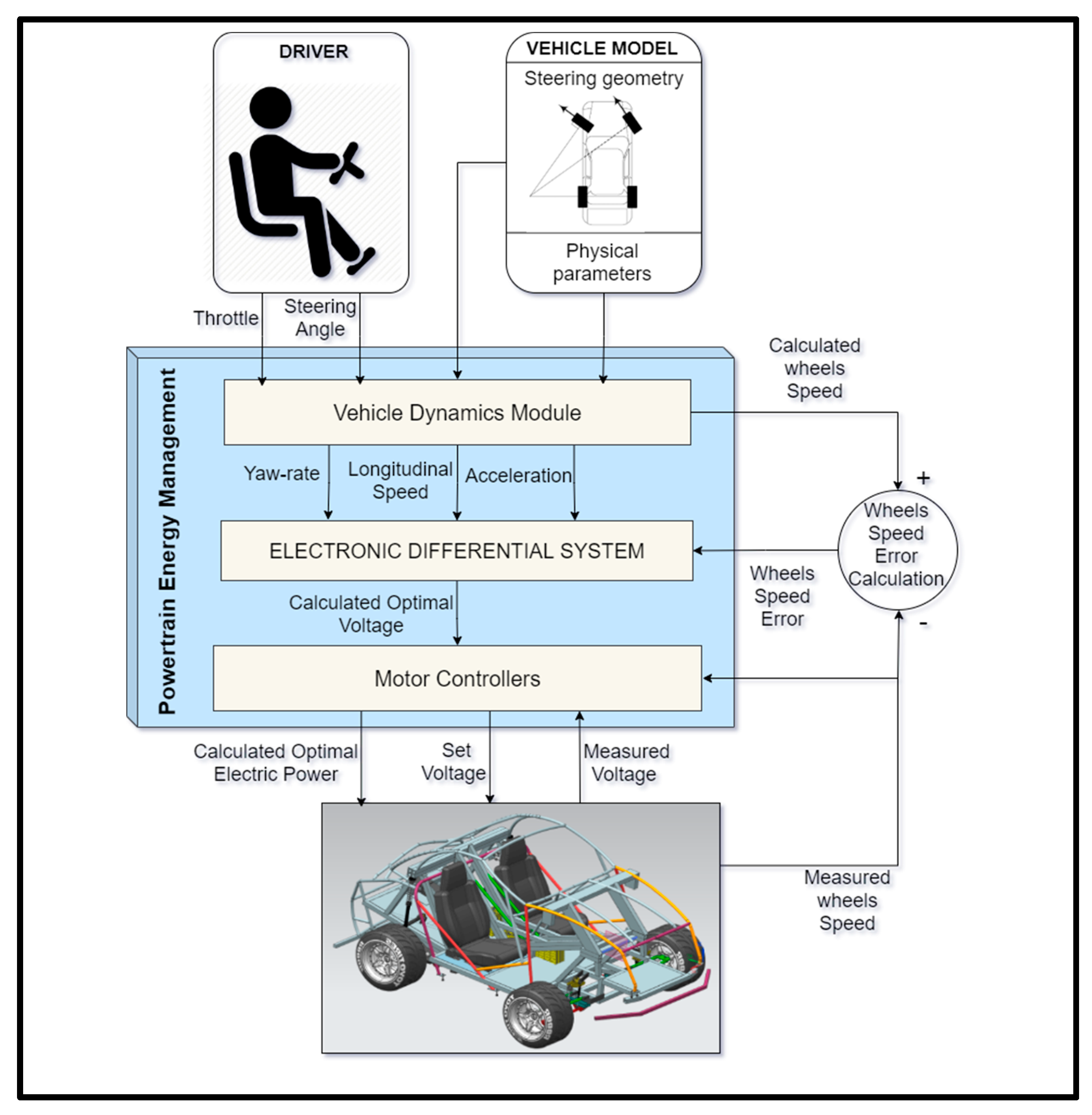
Many studies have been conducted about EV efficiency [12,13,14], but few focus on the particular case of IWMEVs [15]. The Ackermann steering geometry is the starting point of most proposed models for wheel speed differentiation [16]. It specifies the geometric relationships that should be complied with to achieve an optimum vehicle performance during turning maneuvers, as stated in the vehicle dynamics literature [17]. The essential inputs for the EDSs proposed in other works are the steering angle and the throttle position [18]. For the EDS presented in this work, the inputs mentioned earlier are also used, complete with the vehicle’s longitudinal speed information. The modeling of the IWMEV results in a complex nonlinear system due to the tire characteristics during a turning or direction-changing process [19]; rapid steering or a low-adhesion-coefficient road can cause vehicle instability like tire slipping causing the driver to lose control. The testing of the EDS proposed in this work was performed at low speeds and maintaining low mechanical power demand on the testing vehicle; this guaranteed vehicle stability and eliminated the possibility of slipping during testing [20], simplifying the vehicle dynamics modeling and allowing for energy interactions to be better observed.
The dynamics stability control approach is used by Hua et al. in their work [21]. Their proposed EDS follows the yaw rate’s value closely and distributes the torque on both sides to ensure steering performance and driving stability. Using an input signal, the steering angle values, and the vehicle speed, their proposed fuzzy logic controller calculates the additional yaw moment necessary to maintain the vehicle’s stability. Another proposed approach is the one presented by Daya et al. [22]. They introduce an EDS based on wavelength control, transforming the steering angle and the throttle input into frequency components to calculate the respective gains fed into the system as input to the motors. Daya et al. also compare the wavelength controller with their own PID controller. It is noticeable that the wavelength controller provides a smoother response with less overshot and a faster settling time than the PID controller. Zhou et al. [23] acknowledge the nonlinearity of the vehicle dynamics in their proposed EDS, including the combined effects and interactions of the longitudinal, lateral, and yaw dynamics together with tire dynamics. The EDS calculations are made by a Model Predictive Control (MPC) controller that processes the vehicle dynamics variables, achieving suitable stability parameters. MPC theory is a recurrent method in vehicle dynamics control [24]. Hu et al. [25] used MPC for torque distribution in a IWMEV that included the motor’s efficiency map to reduce energy consumption, achieving savings of 4.5% and 0.8% for lane changing and straight acceleration maneuvers, respectively. Xu et al. [26] also used MPC for torque control in their IWMEV simulation model to optimize their in-wheel motors’ regenerative braking function.
EDS works focus on vehicle dynamics; however, there have been efforts in combining dynamics control with energy optimization since both tasks imply powertrain control and actuation. Ma et al. [27] use torque allocation to reduce side slipping by implementing a penalty function within its controller; reducing side slip angle has positive effects on the vehicle dynamics and reduces energy losses in the tire due to tire wear. Zhao et al. [28] proposed a system with a dynamics stability approach, using a holistic corner controller for a vehicle with four in-wheel motors to reduce tire slipping and thus tire wear, controlling the yaw rate of the car and finally achieving a reduction of tire slip energy of 16.62%.
This paper’s main contribution consists of an EDS focused on energy management and implementation in an IWMEV test car. The EDS manages energy by calculating the optimal speed for each drive wheel, using proportional control and a deterministic vehicle model. The EDS then allocates the required power to each in-wheel motor through the motor controllers, while these handle the torque applied at the contact patch of the wheels with the ground. Exhaustive experimental testing has demonstrated that the proposed EDS design significantly improves vehicle longitudinal dynamics and powertrain energy. In particular, the design has been shown savings of up to 21.4% over a vehicle without EDS. The tests and analyses that lead to these results are widely described in the following sections of the document.

3. Methodology

The methodology for EDS development is inspired by the classical design methodology [29]. This methodology suits the project’s scope because it includes a preparatory phase, conceptualizing an idea based on a given problem, conceptual design, embodiment design, system development, physical model implementation, and testing (see Figure 1).

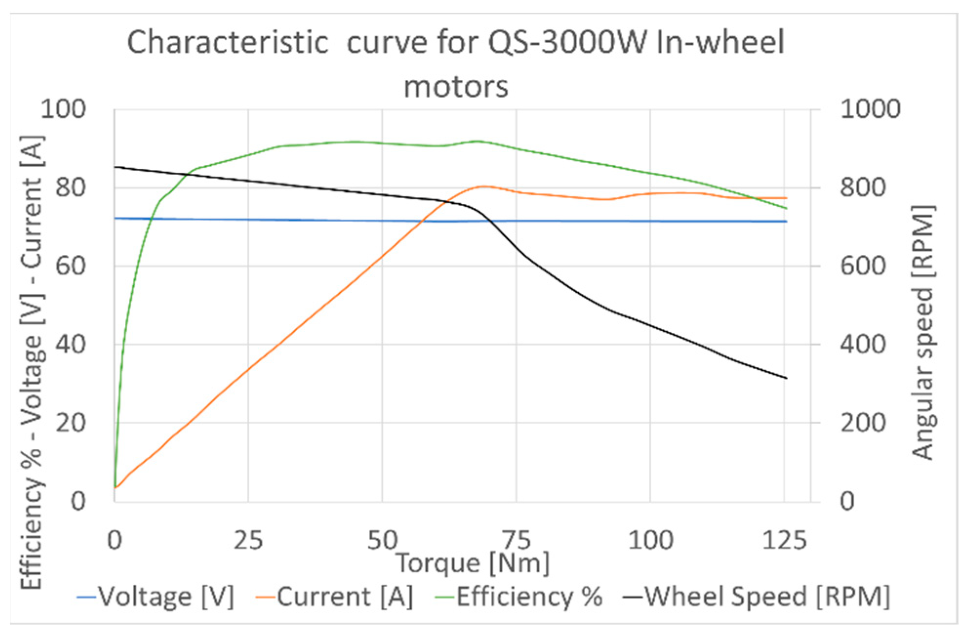
4. Experimental Test Vehicle

This work’s experimental platform is a test vehicle available at the Research Center for Automotive Mechatronics (CIMA) (Figure 2). This test vehicle is a recreational vehicle that features a lightweight aluminum chassis. The car was specially designed and built to research electric cars, in particular IWMEVs. Vehicle components have been adapted to the chassis and are, for the most part, commercial components. The purpose of this test vehicle is primarily to experience realistic vehicle dynamics conditions.
The powertrain consists of two electric motors with a nominal power of 3 kW each. Electric motors are commercial [ref: www.qsmotor.com, accessed on 12 June 2020] and are direct-current brushless motors. The motors are installed in each of the vehicle’s rear wheels. The operating region of the electric motors is in the voltage range of 48 to 72 volts. These motors’ behavior curves are shown in Figure 3, where the torque behavior versus speed and efficiency are described in the corresponding figure.
Figure 4 shows the electronic architecture to implement the EDS, with the components labeled with numbers from one to six. In particular, one encoder sensor (1) measures the steering wheel angle. The corresponding angular speeds are measured using the three hall effect sensors installed on each rear wheel (2). In addition, a potentiometer (3) has been used to measure the throttle (accelerator pedal). All sensors connect to two systems, Arduino™ UNO boards. These provide connectivity to the onboard computer (4) with an application in MATLAB’s App Designer™ with the algorithm programming code. Finally, two motor controllers (5) and the battery pack (6) are also shown in the figure.
The operation of the entire system is described as follows. The EDS reads inputs and calculates angular speeds required at the drive wheels. The motor controllers receive instructions from the EDS and manage the energy delivered to the motors. A battery pack stores and provides the energy required by the electric motors. The electric in-wheel motors have the mechanical power as instructed by the controllers and report their angular speed to the EDS. The throttle pedal reads the acceleration desired by the user and sends the voltage signal to the EDS. The rotary encoder reads the position of the steering wheel and sends the information to the EDS. Figure 4 shows signal communication and electric power delivery in the direction of the arrows.
Table 1 summarizes the vehicle’s characteristics and the results obtained during the performance tests applied using CIMA’s laboratory equipment, such as the chassis dynamometer.

5. Vehicle Dynamics Modeling

This section describes the vehicle dynamics characteristics and the testing performed to gather this information.

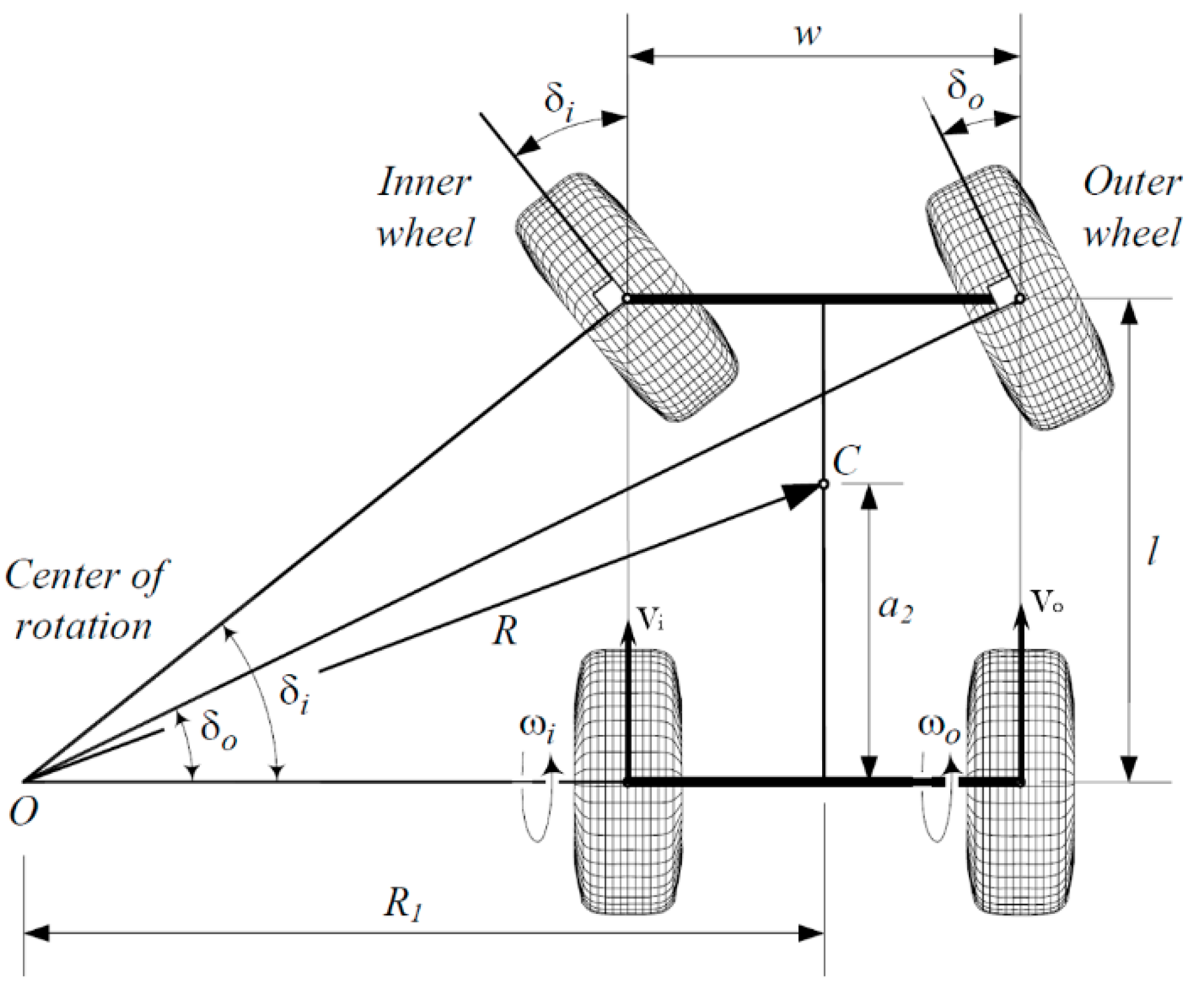
5.1. Steady-State Handling Characteristics

The steady-state handling characteristics of a vehicle provide information on how the vehicle handles the steering and turning maneuvers and provides a classification into three categories: understeer, neutral steer, and oversteer. The classification depends on the vehicle’s understeer coefficient, Kus, a factor calculated as a function of the weight distribution and the tire cornering stiffness, Cα. The normalized cornering coefficient (defined as the cornering stiffness per unit normal load) of all the test car wheels was estimated to have a value of 0.19 (1/deg).
The steering angle required for the vehicle to perform a given curve depends on the wheelbase, turning radius, forward speed, and the mentioned understeer coefficient. The test vehicle’s weight distribution has been measured as 44% and 56% for the front and rear axles, respectively, making its understeer coefficient have a value of −0.632 [deg], which indicates that the vehicle is classified as oversteer. If an oversteer vehicle is accelerated in a constant radius, the driver must decrease the steering angle [17]. This characteristic is considered in the EDS operation. The EDS will respond in real-time to any changes in the user’s steering angle to maintain the vehicle in the desired path and at the desired speed.

5.2. Preliminary Dynamics Testing of VR1

The vehicle’s preliminary testing provides critical information later used in developing the EDS, like the power train capabilities and dynamics response to handling maneuvers. The following figures present the testing results of the test car using the dynamometer. Figure 5 shows the acceleration and speed curves, and Figure 6 contains the torque response and mechanic power development of the powertrain.

5.3. Kinematics

The basis for the EDS is the geometry implicit in the Ackermann equations. These equations describe the geometric and dynamic relationships that need to be achieved to guarantee that a no-slipping condition occurs in the drive wheels during a turning maneuver. The base equations were taken from Jazar [30], and their development to obtain the drive wheels’ angular speed is shown below. The symbols used in the equations are in Appendix A.
Figure 7 shows the existing relationship between the parameters of a car making a turn with a radius R1. The angles δi and δo must be such that the line coming from the turning center-point O is perpendicular to the left and right wheel’s lateral plane, which guarantees that both turning wheels are in full rolling behavior, not slipping. The rear axle is of interest to establish the correspondent geometric and dynamics equations for the drive wheels.
Figure 8 shows the same rear-drive car with more parameters, like the distance a2 between the center of mass C and the rear axle, the distance R from the turning center-point O to the center of mass, the angular speed of each rear wheel ωi and ωo, and the longitudinal speed vector of the inner and outer rear wheel Vi and Vo, respectively. The relationship between these parameters allows the construction of the following equations:
R = a 2 2 + l 2   c o t 2   δ
Equation (1) shows the vehicle’s turning radius as a function of δ, where δ is the cot-average of the inner and outer steer angles and l distance between the front and rear axles. Equation (2) shows the equivalent angle δ when the front wheels have different values.
c o t ( δ ) = c o t ( δ o ) + c o t ( δ i ) 2
The test car’s steering mechanism characteristics classify it as a parallel steer (Figure 9). This means that the steering angle of both front wheels is equal (Equation (3)). The effects of having a steering mechanism that does not adhere to the Ackerman geometry are increased tire scrub during cornering, tire wear, and increased steering effort. The magnitude of not having Ackerman steering is variable and depends on the steering angle or the radii of the turning maneuver being performed. For all the tests considered in this work, the steering angles were at or below 16 (deg), so the deviation from the ideal curve was minimal, and the effects can be neglected.
δ i = δ o = δ  
From the geometric relations in Figure 8, we obtain Equation (4).
C o t   δ = R 1 l
The dynamics equations for each rear wheel’s longitudinal speed (Vi and Vo) and the geometric proportions of a vehicle turning left can be written as shown in Equations (5) and (6) for the inner wheel and the outer wheel, respectively. The wheel’s effective radius is denoted by Rw and the Yaw-rate of the vehicle by YR.
V i = Y R ( R 1 w 2 ) = ω i R w
V o = Y R ( R 1 + w 2 ) = ω o R w
Replacing Equation (4) with Equations (5) and (6) and solving the angular speed of the inner (ωi) and outer (ωo) wheels of the rear axle of a rear-drive car, we obtain Equations (7) and (8).
ω i = Y R ( l * C o t ( δ ) w 2 ) R w                  
ω o = Y R ( l * C o t ( δ ) + w 2 ) R w                        
The former equations are the base for the EDS and are programmed in a series of successive code lines that calculate the required speed for each of the rear wheels as a function of the car’s instantaneous turning angle and velocity. The motor controllers set the voltage on the motors to achieve the individual speed calculated for each rear wheel, ωi, and ωo. This information is then sent to the EDS to recalculate the power parameters for the wheels in the next iteration.

6. EDS Development

After obtaining the critical characteristics of the vehicle dynamics, the EDS could be developed.

EDS Development Using MATLAB

The program’s main purpose is to maintain the required angular velocity differential between the two rear wheels. However, it also needs to control some other aspects, like acknowledging the motors’ maximum speed capabilities and making smooth transitions between speeds to reduce excessive vehicle accelerations. The main functions of the EDS algorithm are shown in Figure 10.
The EDS must acknowledge the limited capabilities of the hardware. In this case, the electric motors have a maximum angular speed of 65 (rad/s). The motor’s manufacturer specified this value, and it was confirmed by testing the electric vehicle in a chassis dynamometer. In principle, the EDS must guarantee that the two wheels’ speed sustains a calculated difference. If a turning maneuver at a given speed requires that the external wheel goes at an angular speed higher than the maximum allowed by the in-wheel motor, the total longitudinal speed of the car must be reduced so that the system keeps working within its limits.
Considering the sensors’ specifications, the sampling period for the analog signals measured by the EDS was defined so that the aliasing was avoided [31]. The variables in the control loop and the values for the motor’s speed are calculated for each computational cycle (490 Hz). Still, the actuation introduces a delay so that the motor’s speeds are set 10 times per second.

7. Experimental Setup Specifications

This section provides information on the testing performed to evaluate the EDS. It is of particular interest to evaluate its functionality in terms of longitudinal speed control and energy management capabilities. For the testing design, it was necessary to have the vehicle perform turning maneuvers to notice the EDS effects. This section presents the different tests and the specific conditions of the experiments. It includes graphic profiles of different variables and detailed instructions of the testing procedures.
Two different tests were designed and were applied to the testing vehicle. The speed control and acceleration testing provided information on the longitudinal performance of the test vehicle, providing data for both speed and acceleration analysis. The energy management test provided data for the energy allocation performance analysis.

7.1. EDS Speed Control and Acceleration Testing

The longitudinal dynamics tests were performed on even terrain by accelerating the vehicle to a moderated speed and performing turning maneuvers. A zig-zag steering angle pattern was applied, starting at zero degrees and then turning left and right seven degrees in both directions with the constant throttle. The complete specifications of the performed experiments are described in Figure 11.

7.2. Energy Management Testing

An onboard current and voltage measurement device (Dewesoft’s SIRIUS™) was used to register the energy consumed by each motor and the instantaneous electric power demanded. This set of tests consisted of driving in circles with a constant radius while recording dynamics and energy data. For the energy consumption tests, the throttle position is kept constant for the duration of the tests, and the maneuver starts with the vehicle speed at 11 (km/h). In addition, no braking is applied, and the turning maneuver is performed with a constant steering angle of 16 (deg) on even ground. Again, the turning maneuver tests were performed with the EDS activated and deactivated. The details of the experiments are presented in Figure 12.

8. Results and Discussion

This section presents a further analysis of the EDS, looking at its impact on the vehicle’s dynamic and energetic performance. The following results were obtained by employing the test procedures described in Section 7.

8.1. EDS Results on Speed Control during the Turning Maneuvers

Tests were performed on the vehicle with the EDS disabled to be used as a baseline; results are shown in Figure 13. As we could observe, the vehicle’s longitudinal velocity presented a variation of 8.55% from its original velocity during the turning maneuvers. This is an undesired effect. It is the EDS’s objective to compensate the relative angular velocities of both wheels to maintain the vehicle’s net longitudinal speed constant unless the user changes the throttle position. The same tests were carried out again with the EDS activated (Figure 14). In this case, the EDS successfully reduced longitudinal velocity variation during the turning maneuvers to 4.85%.

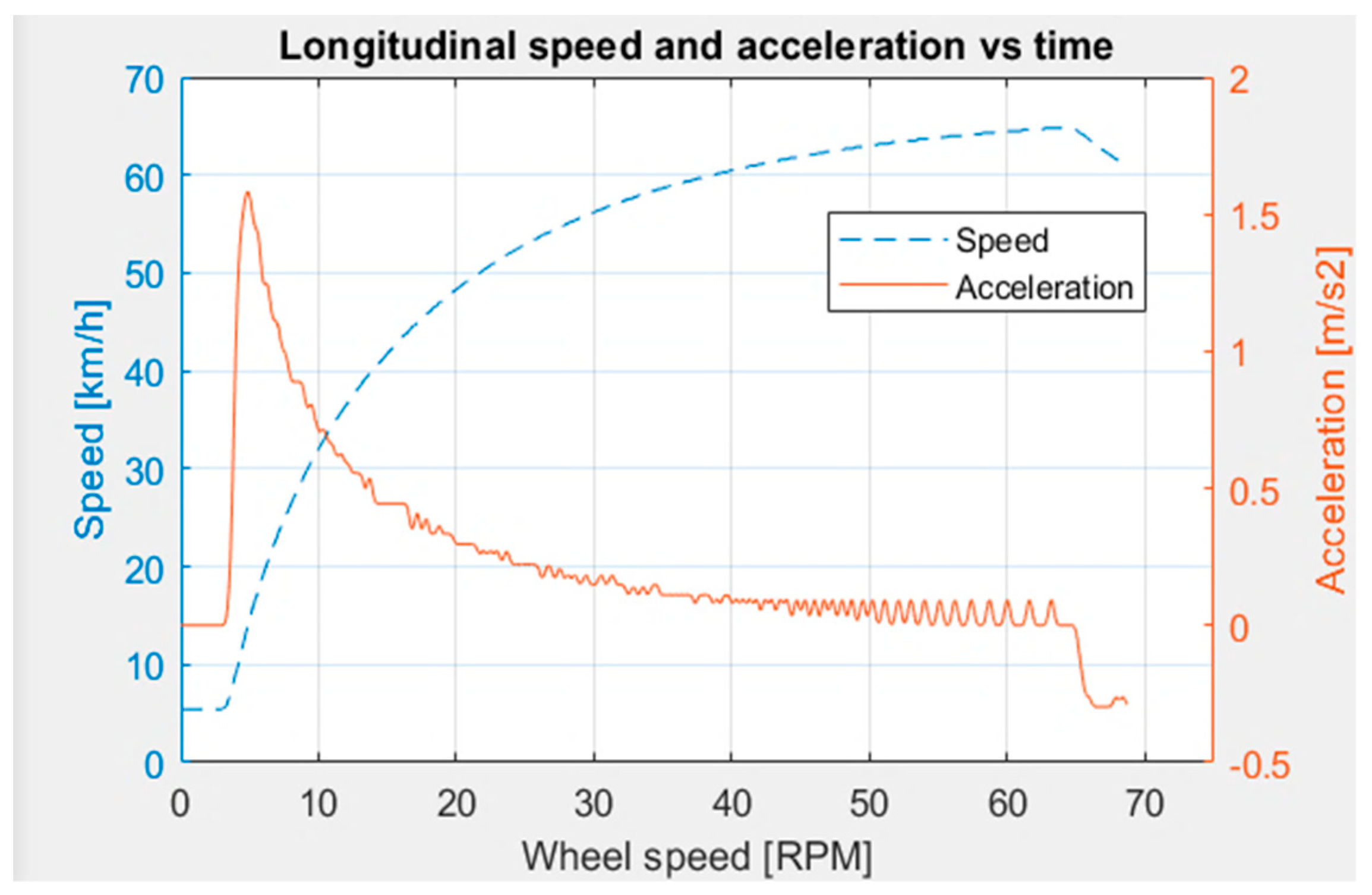
8.2. Acceleration Analysis

Acceleration is a critical factor to consider while evaluating the EDS performance. In this case, the vehicle should not present any significant acceleration spikes that the passengers perceive. The accelerations to observe are the longitudinal acceleration, the individual angular accelerations, and the lateral acceleration.
Results for longitudinal acceleration are shown in Table 2, with and without the EDS. The highest values for longitudinal acceleration were around 1.5 (m/s2), both positive and negative. During most of the acceleration tests, the longitudinal acceleration stayed between −1.5 and 0.5 [m/s2], a comfortable value for the passengers.
During data analysis, it was also observed that the magnitudes of the instant acceleration values were similar for activated EDS and deactivated EDS; the difference is the allocation of this acceleration event performed by the EDS when it is active, controlling the longitudinal speed and reducing its undesired variation. The acceleration results are presented in Figure 15. The turning maneuver tests are described in Section 7.

8.3. Energy Management Results

The EDS directly affects the power train system and the energy distribution. The measured energy data of a sustained right-turning maneuver for both cases (activated and deactivated EDS) are presented in Table 3. Here we can observe that the power train system’s total consumed energy was 21.4% less with the EDS activated. The power distribution noticeably changed between the two in-wheel electric motors (left and right). For a right turning maneuver, the right wheel required less energy than the left wheel.
The electric power delivered to each motor and the totals are presented in Figure 16A,B for deactivated and activated EDS. The EDS guarantees that the power is delivered according to each motor’s specific energy requirements. The energy management functionality is observed in the orange and gray lines in the power distribution graphs; when the EDS was deactivated, these lines repeatedly crossed during testing, which means that both motors were receiving nearly the same power. Meanwhile, with the EDS enabled, the orange and gray lines stay noticeably separated.
Another interesting remark is that, in both cases, wheel speed differentiation was observed, but the causes were different. In the first case, with the EDS deactivated, cinematic and mechanical restrictions caused the differentiation. Thus, the excess power delivered to the inner wheel was lost as wheel slipping or motor overcurrent heat. On the other hand, when the EDS was activated, the energy was correctly allocated and effectively used to accelerate the vehicle.

9. Conclusions

By closely controlling the relative angular velocities of both rear wheels, the EDS regulated the vehicle’s longitudinal acceleration and had a noticeable effect on the vehicle’s longitudinal speed during turning maneuvers, achieving a decrease in longitudinal speed variation from 8.55% to an average of 4.85% for the same driving maneuvers.
The EDS also improved the power train’s energy performance by avoiding sending excess electric power to the physically restricted inner motor, noticeably minimizing energy losses due to overcurrent heat, wheel slip, and friction. In addition, the outer motor performed better as it now received the correct amount of energy. Depending on the turning radius, the electric power misallocation can account for up to 21.4% of the turning maneuver’s energy. With the EDS’s help, this lost energy was minimized and saved, dramatically improving the vehicle’s energy efficiency.

10. Future Work

There is still plenty of research to be conducted on IWMEV technology; the following are ideas that can further develop electronic differential capabilities:
  • Evaluate advanced control strategies for the EDS, like machine learning models to predict optimal power strategies. The optimization parameters can be measurements provided by onboard sensors, while the model aims to minimize energy in real-time driving.
  • Study the effects of integrating regenerative braking functionality into the EDS.
  • Increase the number of onboard sensors and include IMUs to enhance vehicle dynamics together with energy management.
  • Evaluate EDS capabilities in new terrains and driving scenarios, like uneven ground and steep slopes, to find new fields for potential improvement.

Author Contributions

Conceptualization, A.S.-D. and J.d.C.J.-R.; methodology, A.S.-D. and J.d.C.J.-R.; software, J.d.C.J.-R.; validation, J.d.C.J.-R., R.A.R.-M. and A.S.-D.; formal analysis, A.S.-D. and R.A.R.-M.; investigation, J.d.C.J.-R.; resources, A.S.-D.; data curation, J.d.C.J.-R.; writing—original draft preparation, J.d.C.J.-R.; writing—review and editing, J.d.C.J.-R., R.A.R.-M. and A.S.-D.; supervision, A.S.-D., and R.A.R.-M.; project administration, A.S.-D.; funding acquisition, A.S.-D. All authors have read and agreed to the published version of the manuscript.

Funding

Funding was provided by Tecnológico de Monterrey (Grant No. a01368435) and Consejo Nacional de Ciencia y Tecnologia (CONACYT) by the scholarship 867164.

Acknowledgments

We appreciate Martín Rogelio Bustamante Bello’s support and collaboration during the final stages of the project, and we thank Pedro Camelo Romero for proofreading this document.

Conflicts of Interest

The authors declare no conflict of interest.

Appendix A

Table A1. List of acronyms.
AcronymDefinition
EVElectric Vehicle
IWMEVIn-Wheel Motor Electric Vehicle
EDSElectronic Differential System
Table A2. Nomenclature.
VariableDescription
Cdaerodynamic drag coefficient
CMcenter of mass
Cαcornering stiffness
Kusundersteer coefficient
llength between the front and rear axle
Rturning radius
Rwtire effective radius
Vlongitudinal speed
Vispeed of the inner rear wheel
Vospeed of the outer rear wheel
wwheelbase or track of the vehicle
YRyaw rate of the car rad/s
ωithe angular speed of the inside rear tire
ωothe angular speed of the outside rear tire
δisteer angle of the inside front tire
δosteer angle of the outside front tire
δthe equivalent turning angle of the front wheels

References

  1. Altun, F.; Tekin, S.A.; Gurel, S.; Cernat, M. Design, and Optimization of Electric Cars. A Review of Technological Advances. In Proceedings of the 2019 8th International Conference on Renewable Energy Research and Applications (ICRERA); Institute of Electrical and Electronics Engineers (IEEE): Piscataway, NJ, USA, 2019; pp. 645–650. [Google Scholar] [CrossRef]
  2. Kopelias, P.; Demiridi, E.; Vogiatzis, K.; Skabardonis, A.; Zafiropoulou, V. Connected & autonomous vehicles—Environmental impacts—A review. Sci. Total Environ. 2020, 712, 135237. [Google Scholar] [CrossRef]
  3. Kim, H.; Pyeon, H.; Park, J.S.; Hwang, J.Y.; Lim, S. Autonomous Vehicle Fuel Economy Optimization with Deep Reinforcement Learning. Electronics 2020, 9, 1911. [Google Scholar] [CrossRef]
  4. Tian, Y.; Pei, K.; Jana, S.; Ray, B. Deep Test: Automated Testing of Deep-Neural-Network-Driven Autonomous Cars. In Proceedings of the 40th International Conference on Software Engineering: Software Engineering in Practice, Gothenburg, Sweden, 27 May–3 June 2018; Association for Computing Machinery (ACM): New York, NY, USA, 2018; pp. 303–314. [Google Scholar] [CrossRef]
  5. Sforza, A.; Lenzo, B.; Timpone, F. A state-of-the-art review on torque distribution strategies aimed at enhancing energy efficiency for fully electric vehicles with independently actuated drivetrains. Int. J. Mech. Control 2019, 20, 3–13. [Google Scholar]
  6. Bokolo, A., Jr. Applying Enterprise Architecture for Digital Transformation of Electro Mobility towards Sustainable Transportation. In Proceedings of the 2020 on Computers and People Research Conference, Nuremberg, Germany, 19–21 June 2020; Association for Computing Machinery (ACM): New York, NY, USA, 2020; pp. 38–46. [Google Scholar] [CrossRef]
  7. Zhou, H.; Xu, Z.; Liu, L.; Liu, D.; Zhang, L. Design and validation of a novel hydraulic hybrid vehicle with wheel motors. Sci. Prog. 2019, 103, 1–25. [Google Scholar] [CrossRef] [PubMed]
  8. Ravi, A.; Palani, S. Research on Sensorless Control Strategies for Vehicle Stability Using Fuzzy Based EDC. Available online: https://www.semanticscholar.org/paper/Research-on-Sensorless-control-strategies-for-using-Ravi-Palani/5ac09d75bc4427b0eafd00c193b2f92339251f02 (accessed on 15 December 2020).
  9. Bai, Y.; Zheng, Y. Research on acceleration performance of fuel vehicles and electric vehicles based on Advisor. J. Phys. Conf. Ser. 2020, 1676, 012139. [Google Scholar] [CrossRef]
  10. Tan, D.; Ge, G.; Shi, L.; Yang, K. Research status of electronic differential control of electric vehicle driven by in-wheel motor. Int. J. Veh. Saf. 2020, 11, 289. [Google Scholar] [CrossRef]
  11. Milas, N.T.; Tatakis, E.C.; Mitronikas, E.D. Investigation of the operation of an electric city car equipped with electronic differential using CAN-enabled monitoring. In Proceedings of the 4th Panhellenic Conference on Electronics and Telecommunications (PACET 2017), Xanthi, Greece, 17–18 November 2017; pp. 1–4. [Google Scholar] [CrossRef]
  12. Pisu, P.; Rizzoni, G. A Comparative Study of Supervisory Control Strategies for Hybrid Electric Vehicles. IEEE Trans. Control. Syst. Technol. 2007, 15, 506–518. [Google Scholar] [CrossRef]
  13. Wei, X.; Guzzella, L.; Utkin, V.I.; Rizzoni, G. Model-Based Fuel Optimal Control of Hybrid Electric Vehicle Using Variable Structure Control Systems. J. Dyn. Syst. Meas. Control. 2006, 129, 13–19. [Google Scholar] [CrossRef]
  14. Martinez, C.M.; Hu, X.; Cao, D.; Velenis, E.; Gao, B.; Wellers, M. Energy Management in Plug-in Hybrid Electric Vehicles: Recent Progress and a Connected Vehicles Perspective. IEEE Trans. Veh. Technol. 2017, 66, 4534–4549. [Google Scholar] [CrossRef] [Green Version]
  15. Wang, R.; Chen, Y.; Feng, D.; Huang, X.; Wang, J. Development and performance characterization of an electric ground vehicle with independently actuated in-wheel motors. J. Power Sources 2011, 196, 3962–3971. [Google Scholar] [CrossRef]
  16. Nogueira Da Cunha, F.P. Desenvolvimento de um Diferencial Eletrónico para Ves. Master’s Thesis, Faculty of Engineering, University of Porto, Porto, Portugal, 2014. [Google Scholar]
  17. Wong, J.Y. Theory of Ground Vehicles; John Wiley: Hoboken, NJ, USA, 1993. [Google Scholar]
  18. Yıldırım, M.; Oksuztepe, E.; Tanyeri, B.; Kurum, H. Electronic differential system for an electric vehicle with in-wheel motor. In Proceedings of the 2020 IEEE 91st Vehicular Technology Conference (VTC2020-Spring), Online. 25–28 May 2020; IEEE: Piscataway, NJ, USA. [Google Scholar]
  19. Abe, M.; Manning, W. Vehicle Dynamics and Control. In Vehicle Handling Dynamics; Abe, M., Manning, W., Eds.; Butterworth-Heinemann: Oxford, UK, 2009; pp. 1–3. [Google Scholar]
  20. Julio-Rodríguez, J.d.C. Analysis and Implementation of Dynamics Equations in the Development of an Electronic Differential for an Electric Vehicle. Master’s Thesis, Tecnológico de Monterrey, Toluca, Mexico, 2019. [Google Scholar]
  21. Hua, Y.; Jiang, H.; Geng, G. Electronic differential control of 2WD electric vehicle considering steering stability. AIP Conf. Proc. 2017, 1820. [Google Scholar] [CrossRef]
  22. Daya, F.J.L.; Sanjeevikumar, P.; Blaabjerg, F.; Wheeler, P.W.; Ojo, J.O.; Ertas, A.H. Analysis of Wavelet Controller for Robustness in Electronic Differential of Electric Vehicles: An Investigation and Numerical Developments. Electr. Power Compon. Syst. 2016, 44, 1–11. [Google Scholar] [CrossRef] [Green Version]
  23. Zhou, H.; Jia, F.; Jing, H.; Liu, Z.; Guvenc, L. Coordinated Longitudinal and Lateral Motion Control for Four Wheel Independent Motor-Drive Electric Vehicle. IEEE Trans. Veh. Technol. 2018, 67, 3782–3790. [Google Scholar] [CrossRef]
  24. Wang, P.; Liu, Z.; Liu, Q.; Chen, H. An MPC-based manoeuvre stability controller for full drive-by-wire vehicles. Control. Theory Technol. 2019, 17, 357–366. [Google Scholar] [CrossRef]
  25. Hu, X.; Wang, P.; Hu, Y.; Chen, H. A stability-guaranteed and energy-conserving torque distribution strategy for electric vehicles under extreme conditions. Appl. Energy 2020, 259, 114162. [Google Scholar] [CrossRef]
  26. Xu, W.; Chen, H.; Zhao, H.; Ren, B. Torque optimization control for electric vehicles with four in-wheel motors equipped with regenerative braking system. Mechatronics 2019, 57, 95–108. [Google Scholar] [CrossRef]
  27. Ma, Y.; Chen, J.; Zhu, X.; Xu, Y. Lateral stability integrated with energy efficiency control for electric vehicles. Mech. Syst. Signal Process. 2019, 127, 1–15. [Google Scholar] [CrossRef]
  28. Zhao, B.; Xu, N.; Chen, H.; Guo, K.; Huang, Y. Stability control of electric vehicles with in-wheel motors by considering tire slip energy. Mech. Syst. Signal Process. 2019, 118, 340–359. [Google Scholar] [CrossRef]
  29. Birkhofer, H. The Future of Design Methodology; Springer: London, UK, 2011. [Google Scholar]
  30. Jazar, R.N. Vehicle Dynamics; Springer International Publishing: Cham, Switzerland, 2017. [Google Scholar]
  31. Shannon, C.E. A Mathematical Theory of Communication. Bell Syst. Tech. J. 1948, 27, 379–423. [Google Scholar] [CrossRef] [Green Version]
Figure 1. Design methodology of the EDS.
Applsci 11 04679 g001
Figure 2. Test car for IWMEV research.
Applsci 11 04679 g002
Figure 3. In-wheel motor characteristic curve (www.qsmotor.com, accessed on 12 June 2020).
Applsci 11 04679 g003
Figure 4. EDS hardware schematic.
Applsci 11 04679 g004
Figure 5. Acceleration and a top speed of the test car in chassis dynamometer.
Applsci 11 04679 g005
Figure 6. Torque and power characteristic curves of the test car power train.
Applsci 11 04679 g006
Figure 7. A front-wheel-steering vehicle and the Ackermann condition (Jazar, 2008).
Applsci 11 04679 g007
Figure 8. A front-wheel-steering vehicle and steer angles of the inner and outer wheels (Jazar, 2008).
Applsci 11 04679 g008
Figure 9. Comparison of Ackerman steering and parallel steering (Jazar, 2008).
Applsci 11 04679 g009
Figure 10. EDS general diagram.
Applsci 11 04679 g010
Figure 11. Speed and acceleration testing.
Applsci 11 04679 g011
Figure 12. Energy management testing.
Applsci 11 04679 g012
Figure 13. Disabled electronic differential test drive results.
Applsci 11 04679 g013
Figure 14. Reduced variation of the speed with enabled EDS.
Applsci 11 04679 g014
Figure 15. Longitudinal acceleration results without EDS (left) and with EDS (right).
Applsci 11 04679 g015
Figure 16. (A) Power distribution and individual wheel-speed profile for a right turning maneuver with EDS deactivated. (B) Power distribution and individual wheel-speed profile for a right turning maneuver with EDS activated.
Applsci 11 04679 g016
Table 1. Physical parameters of the car test.
Vehicle Information
Power trainRear-drive, in-wheel motors
Weight400 kg (44% front axle–56% rear axle)
Dimensions2.96 m long × 2.14 m wide × 1.53 m high
Power source59 volts—16 Li-ion Cells Battery pack
Frontal area1.82 m2Cd:0.428
Tire effective radius0.25 mRolling Resistance coefficient:0.027
Tire cornering coefficient0.19 (1/deg) (normalized)
Wheelbase1.72 mInter-axle distance:1.89 m
* CM to rear wheels distance0.83 m* CM heigh:0.3 m
Max torque350 N-m
Max acceleration1.54 m/s2Max speed:64 km/h
* CM refers to the center of mass of the vehicle.
Table 2. Acceleration values for zig-zag maneuvers with EDS activated.
Longitudinal Acceleration (m/s2)
Deactivated EDSActivated EDS
Max0.54910.5374
Min−1.5168−1.2662
mean +0.19250.1495
mean −−0.5198−0.1420
Table 3. Energy and power result in a right turning maneuver.
Right Turn with EDS Activated
Left MotorRight MotorTotal
Energy (Wh)2.120.893.01
Average Power (W)621.69262.99884.68
Right Turn with EDS Deactivated
Left MotorRight MotorTotal
Energy (Wh)1.832.003.83
Average Power (W)657.24721.411378.65
Publisher’s Note: MDPI stays neutral with regard to jurisdictional claims in published maps and institutional affiliations.

