A Novel Ultrasonic Trepanning Method for Nomex Honeycomb Core


Abstract
:1. Introduction
2. Ultrasonic Trepanning Process
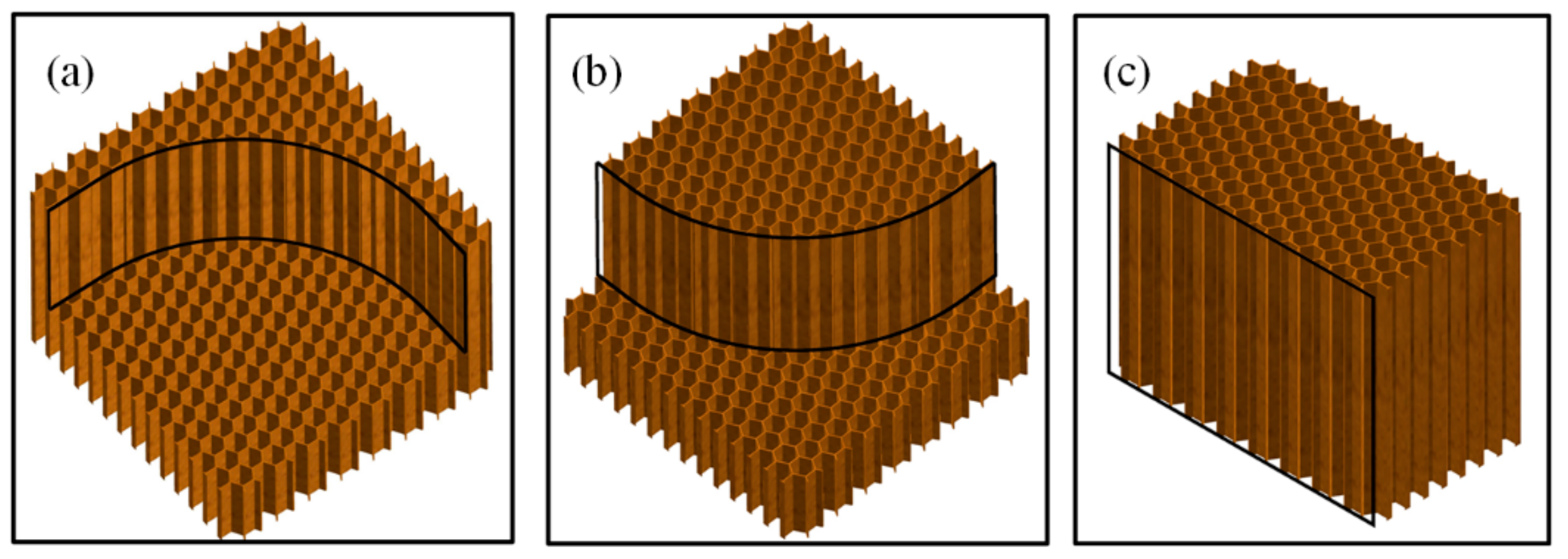
2.1. Ultrasonic Trepanning Strategy
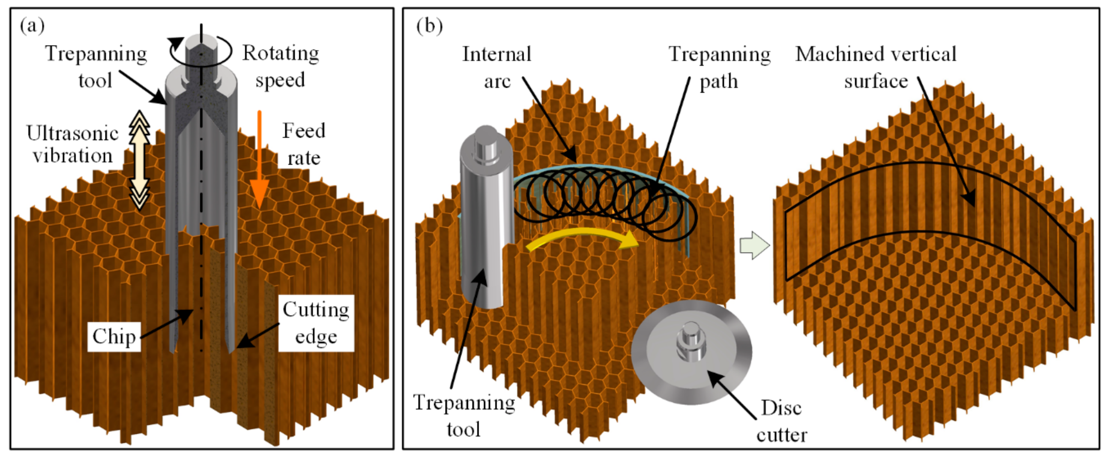
2.1.1. The Ultrasonic Trepanning Method
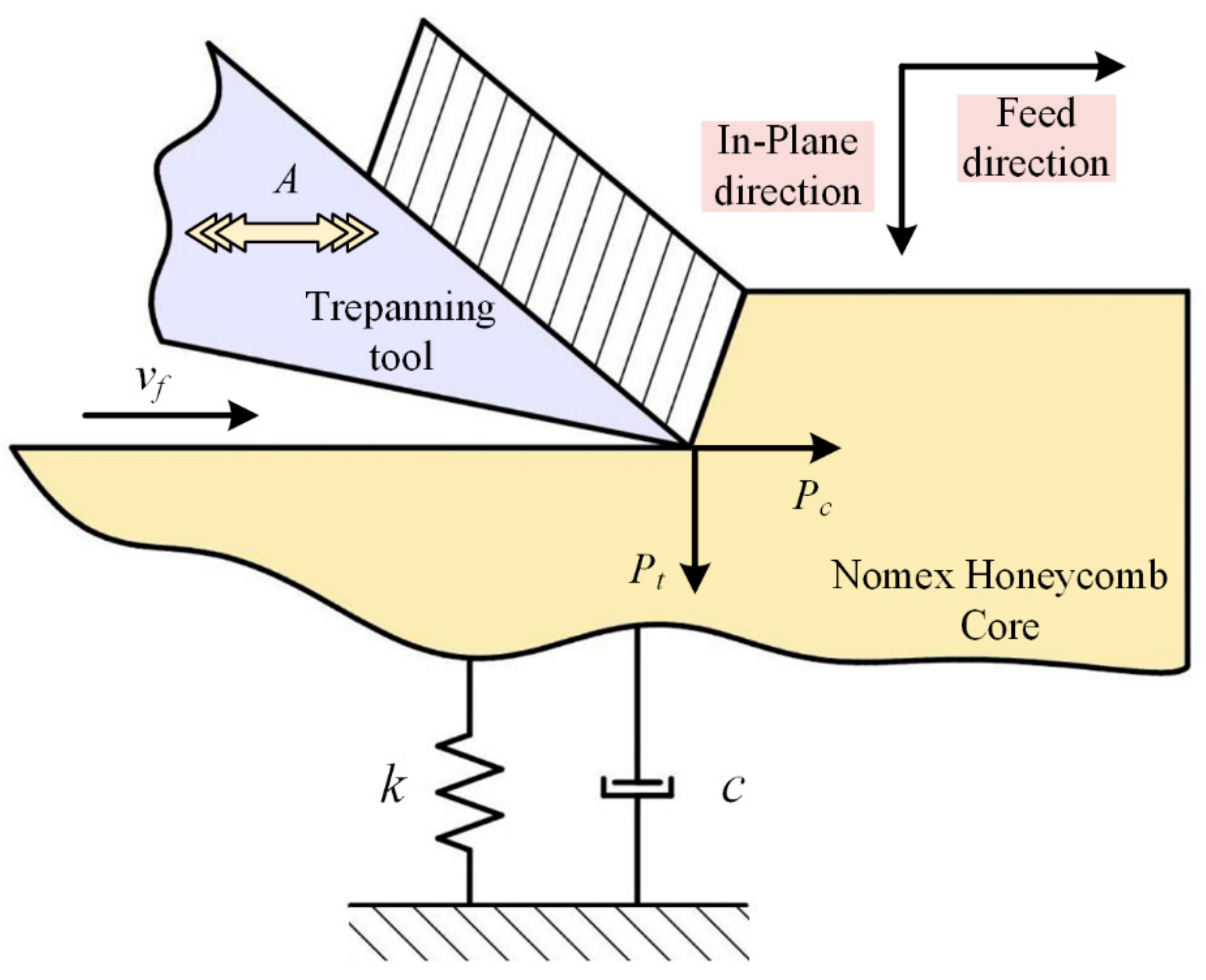
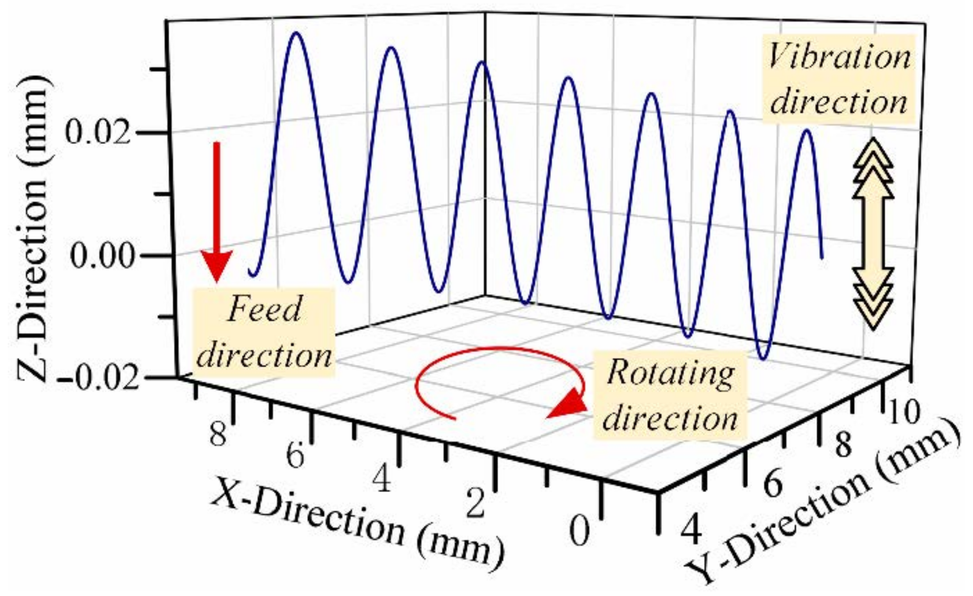
2.1.2. Kinematics Analysis of Ultrasonic Trepanning
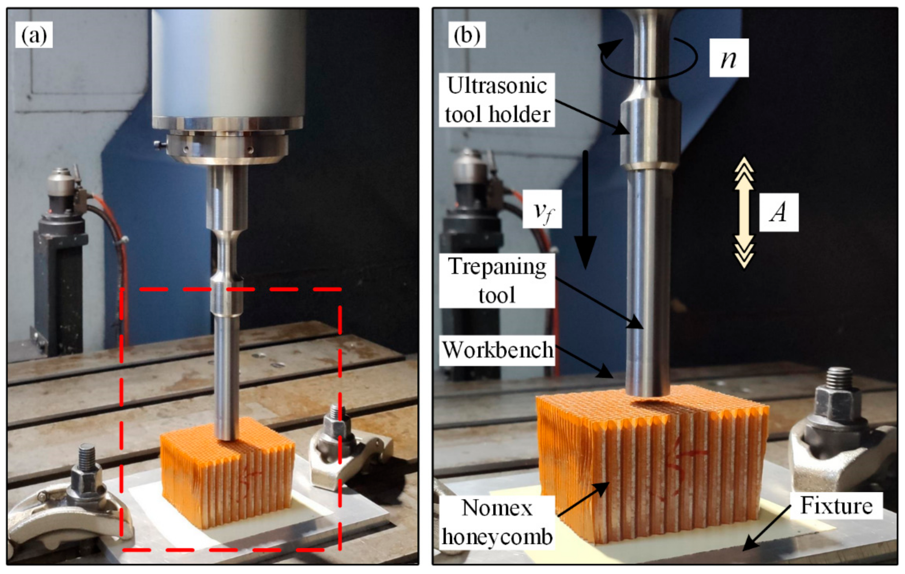
2.2. Ultrasonic Trepanning Tool
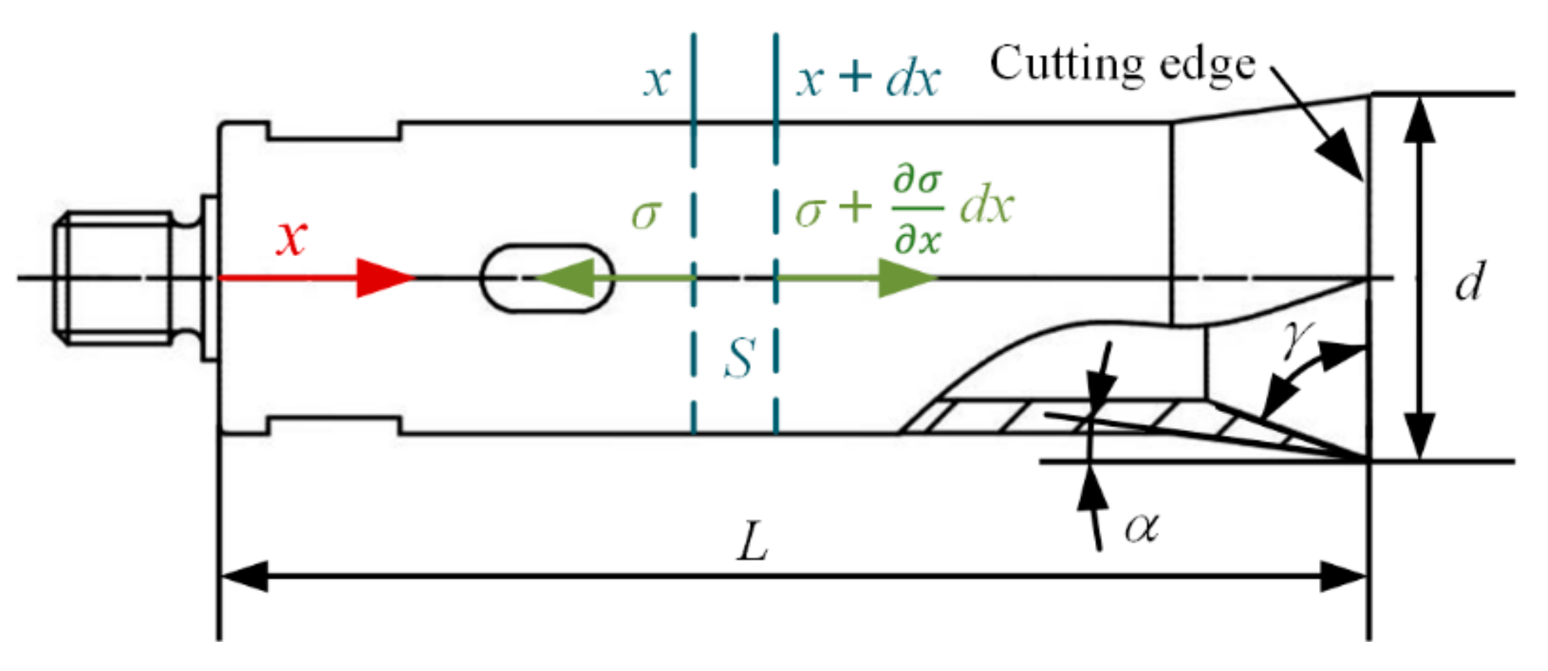
2.2.1. Design of Ultrasonic Trepanning Tool
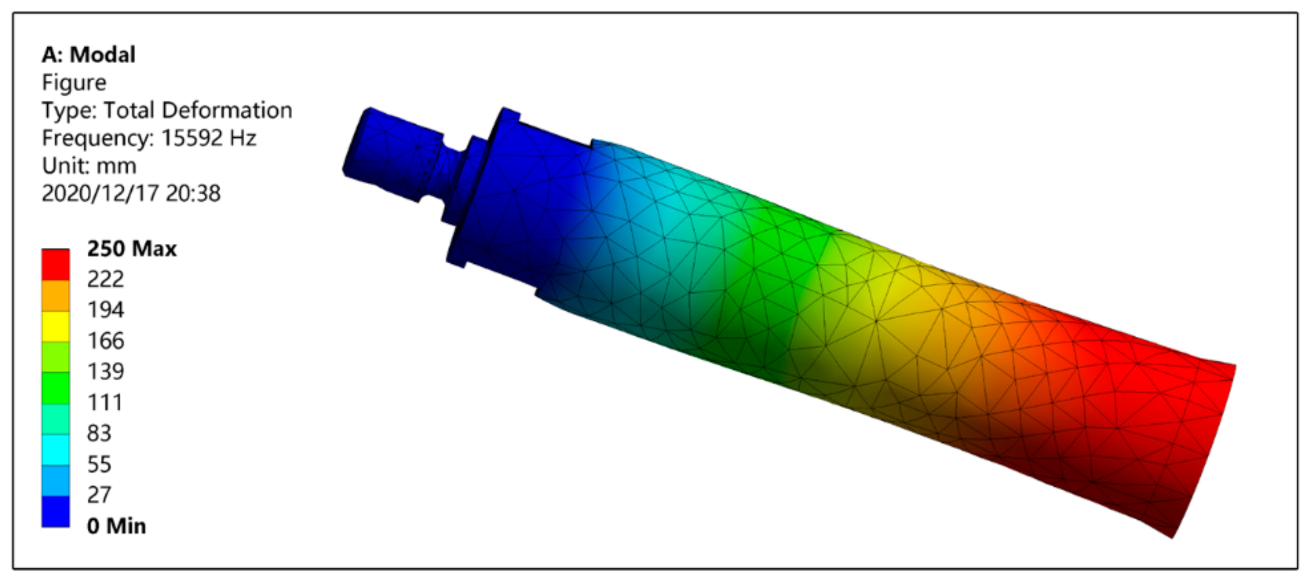
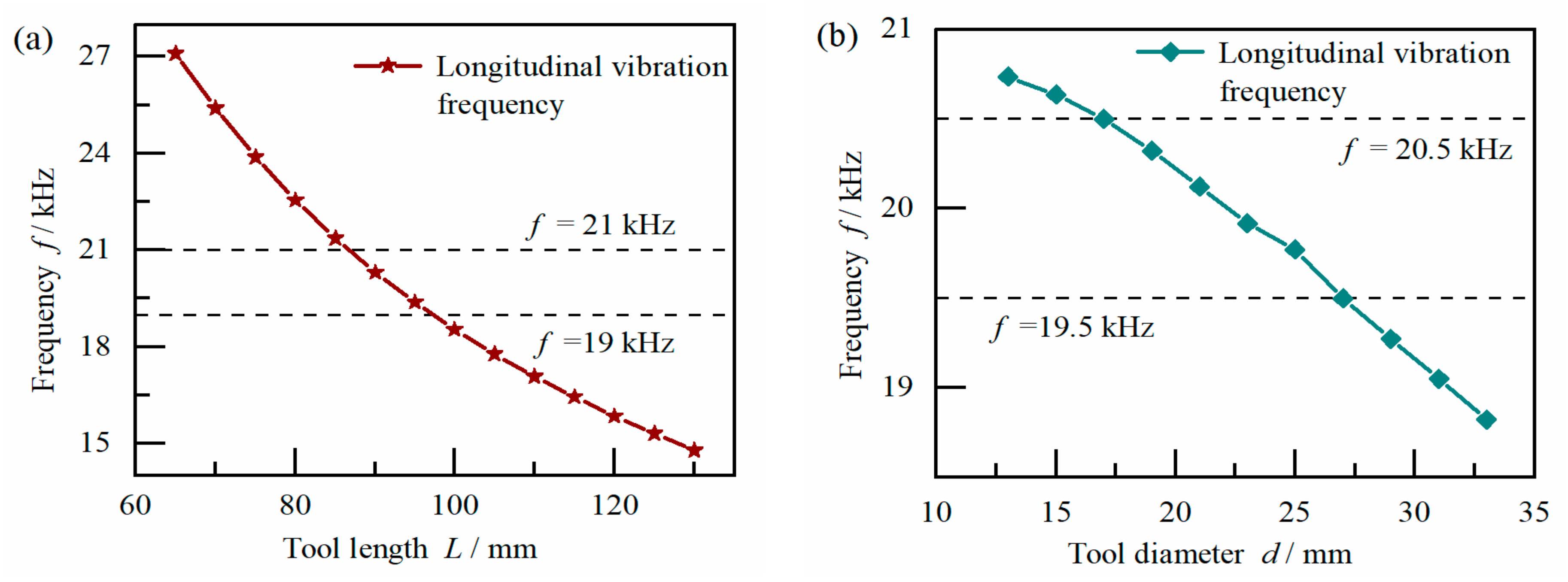
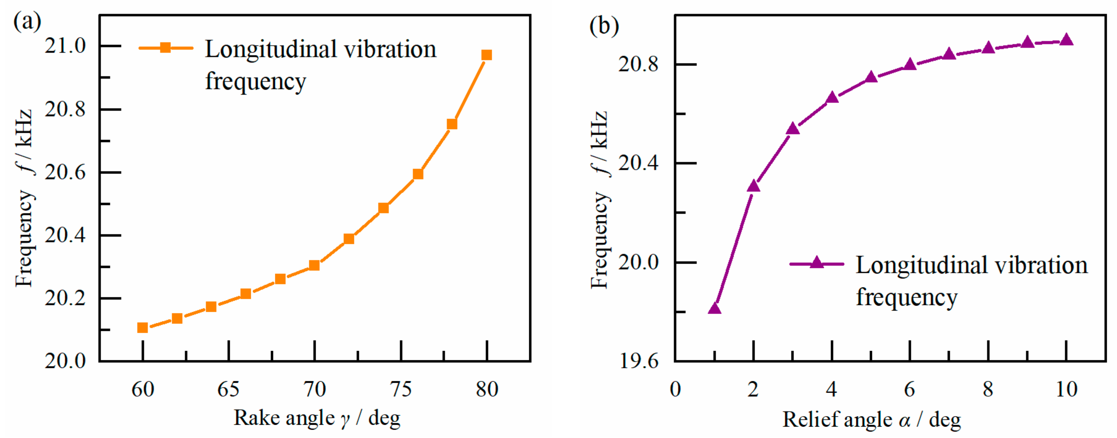
2.2.2. Finite Element Simulation Analysis
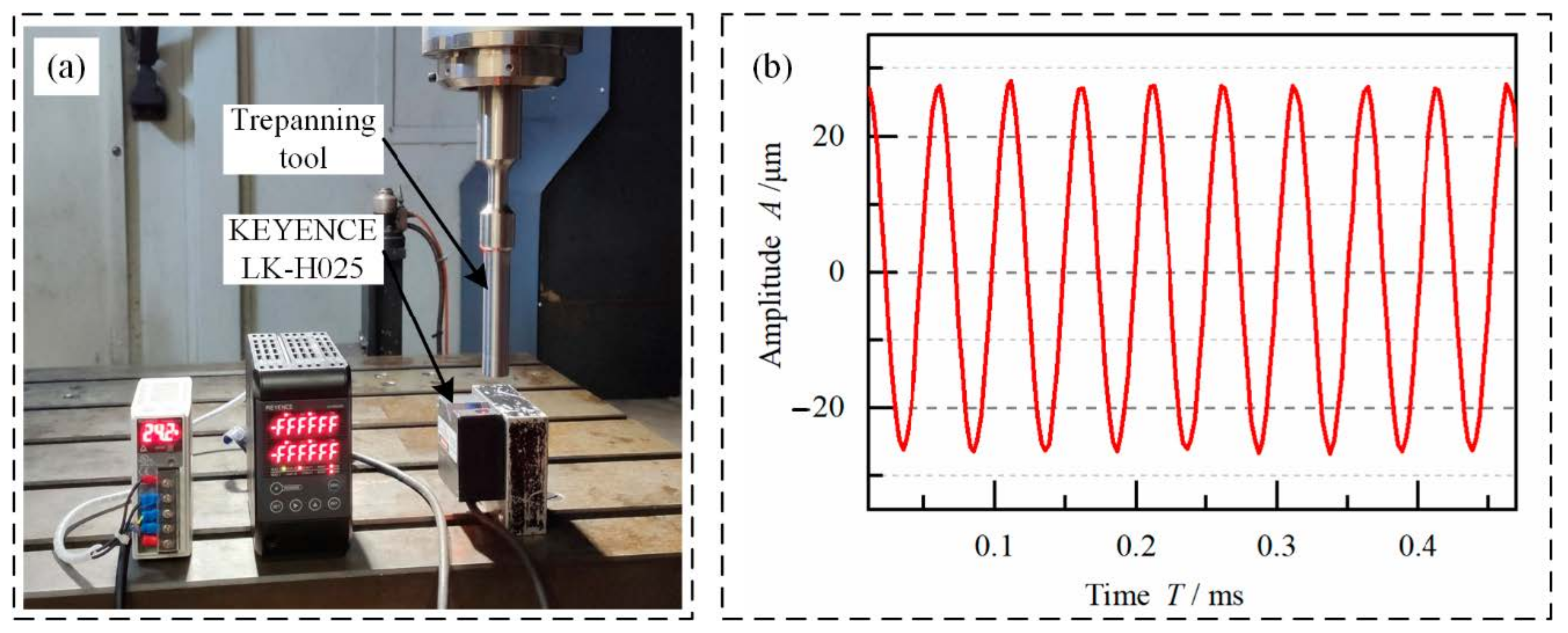
2.2.3. Ultrasonic Vibration Performance Test of Trepanning Tool
3. Theoretical Analysis of Ultrasonic Trepanning Quality
3.1. Dimensional Error in Trepanning
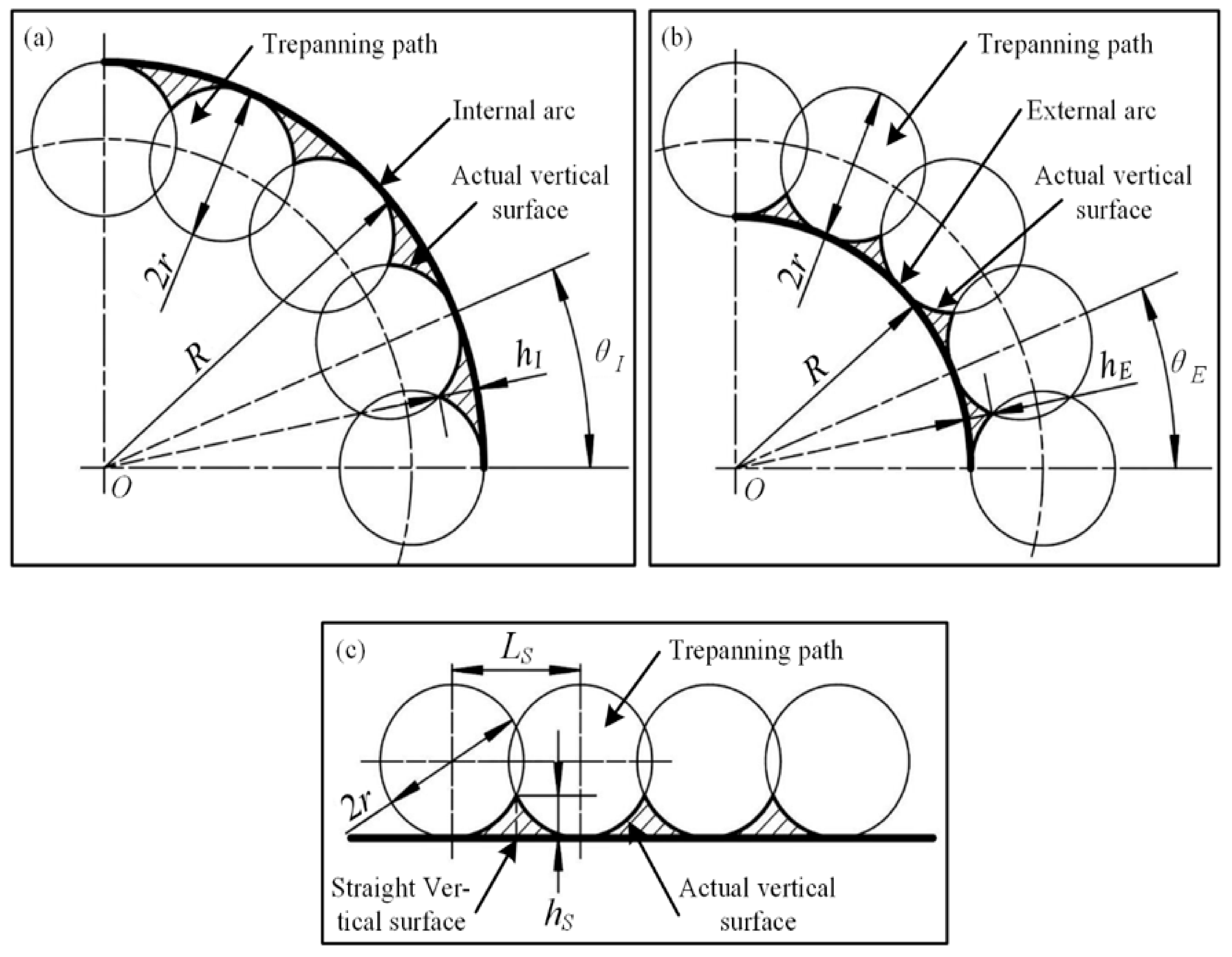
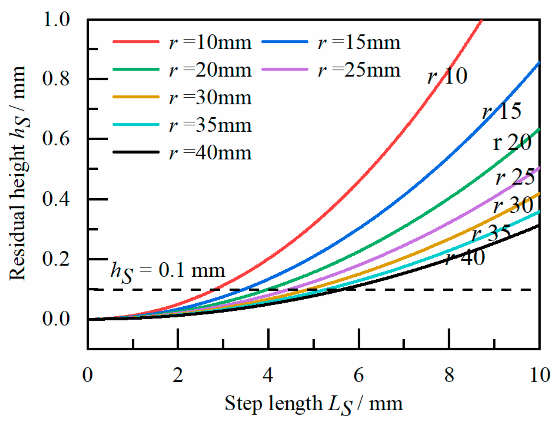
3.1.1. Theoretical Analysis of Dimensional Error in Trepanning
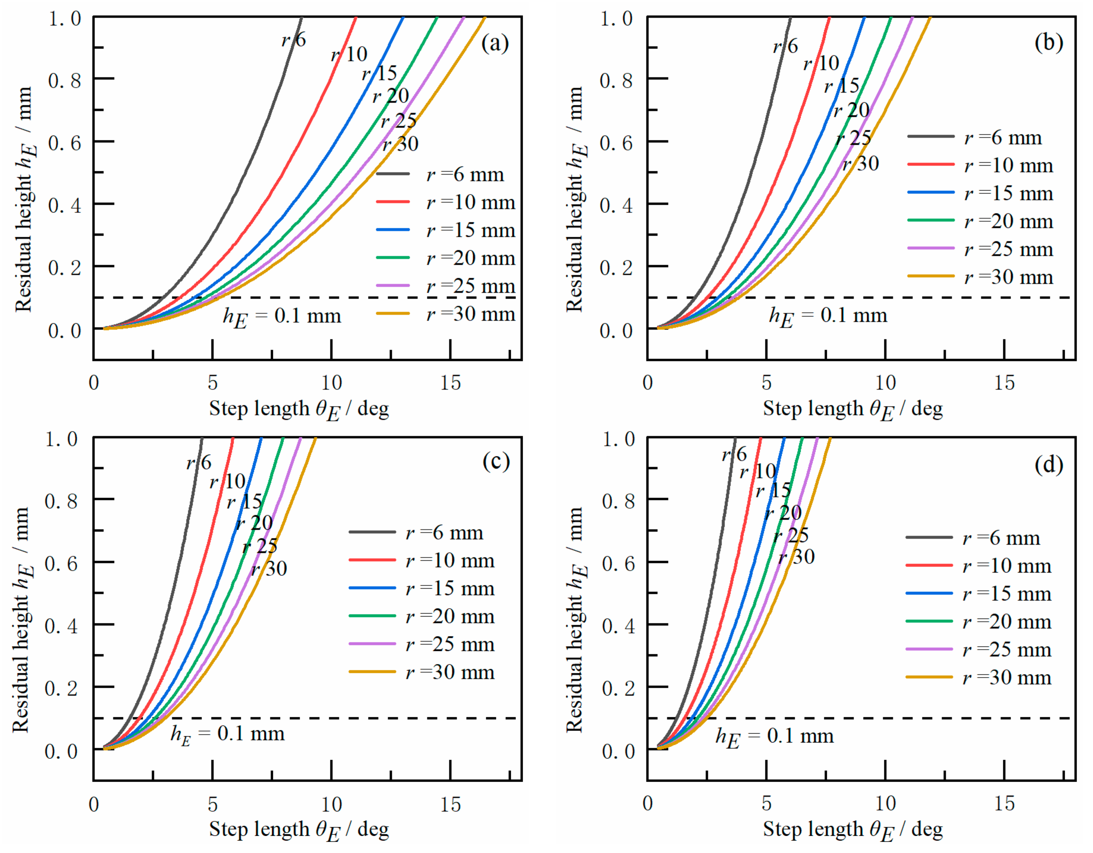
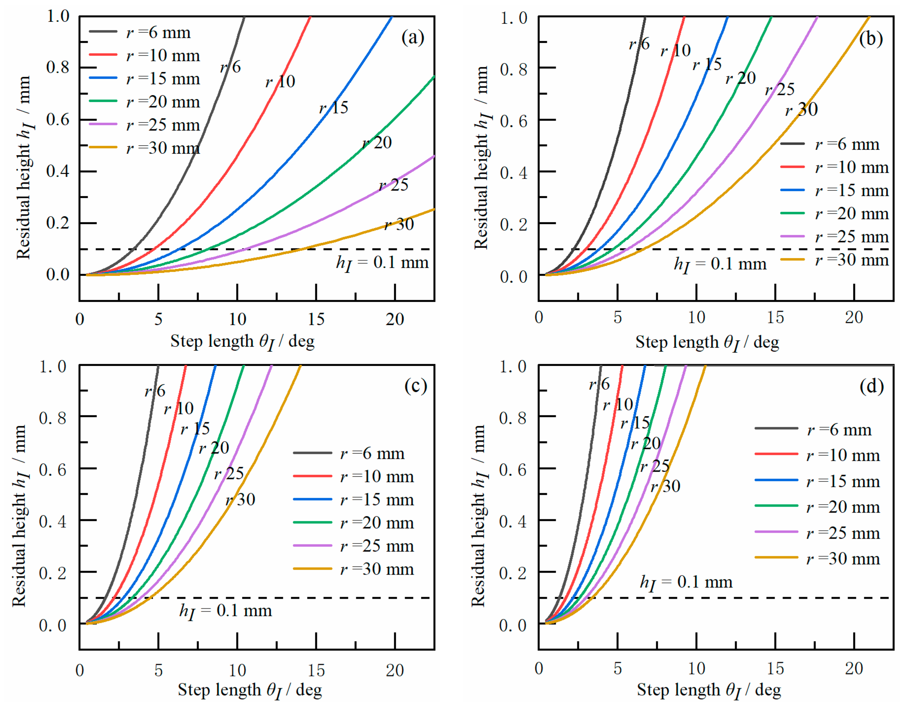
3.1.2. The Influence of Process Parameters on Dimensional Error
3.2. Theoretical Analysis on the Quality of Trepanning Incision
4. Ultrasonic Trepanning Experiment
5. Result and Discussion
5.1. Dimensional Error of Vertical Surface
5.2. Trepanning Incision Quality of Nomex Honeycomb Core
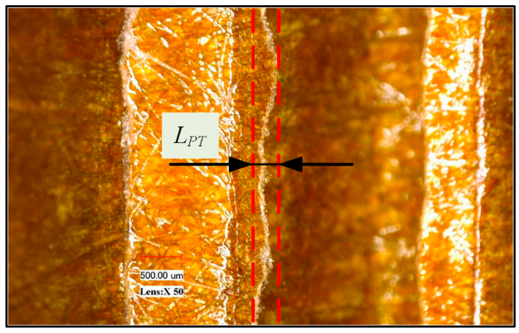
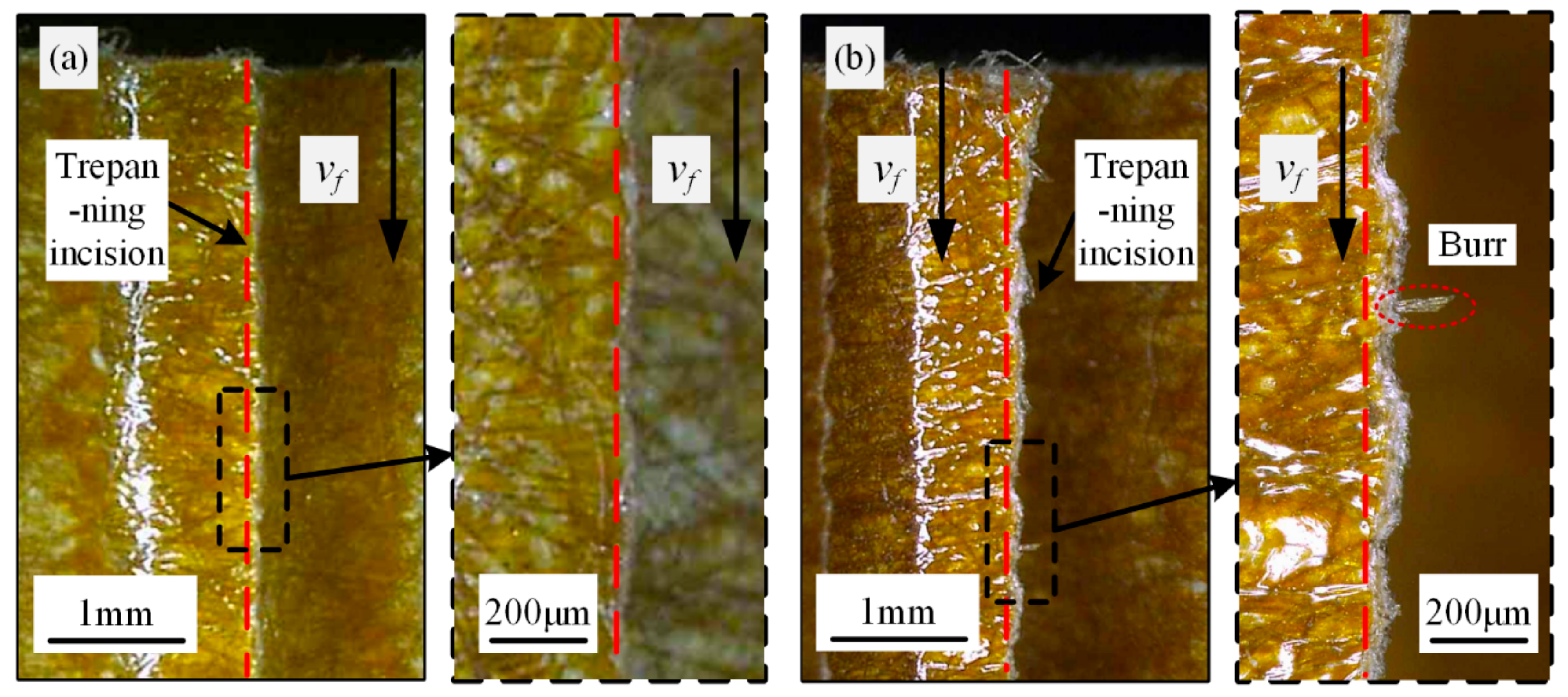
5.2.1. Typical Characteristics of Trepanning Incision
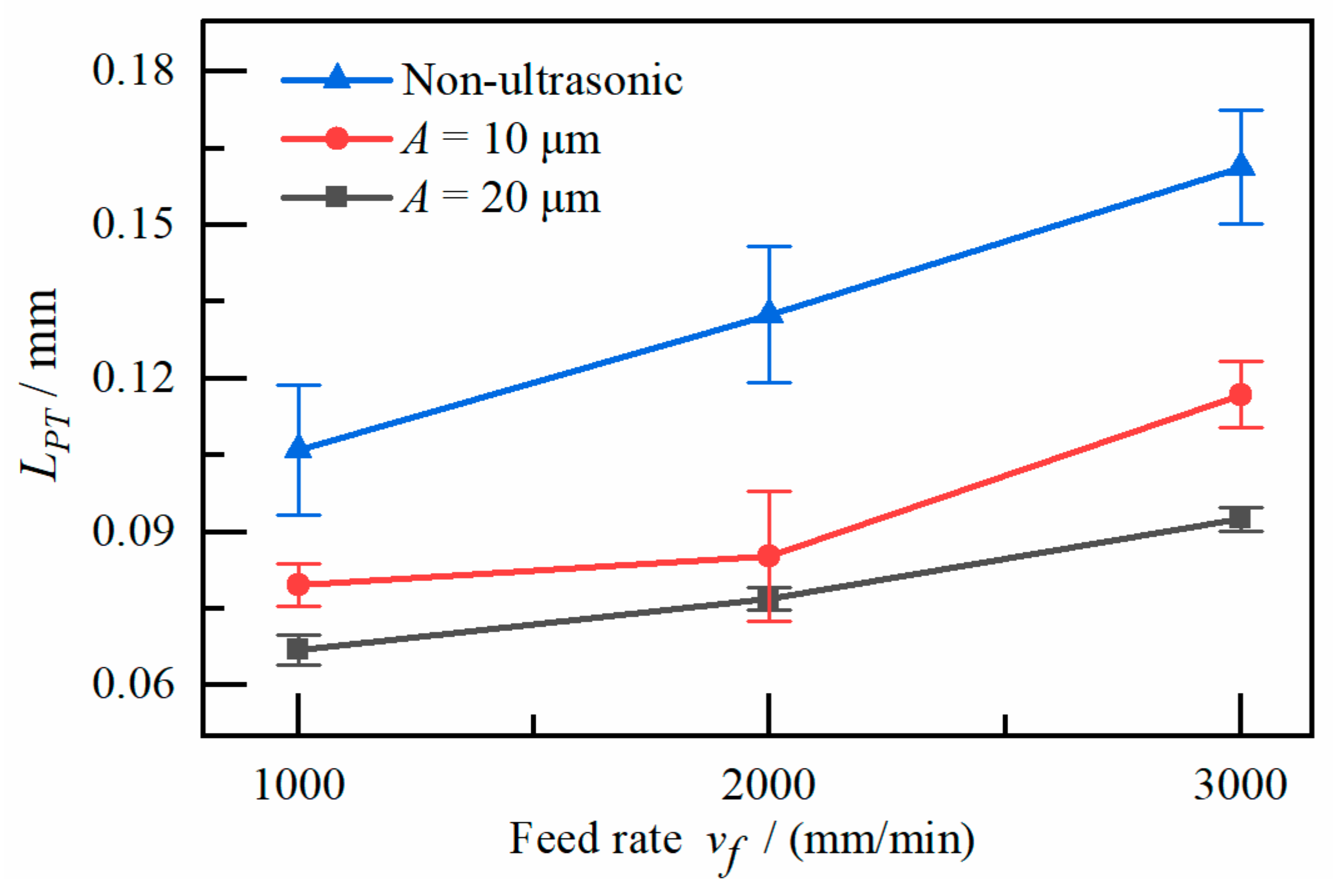
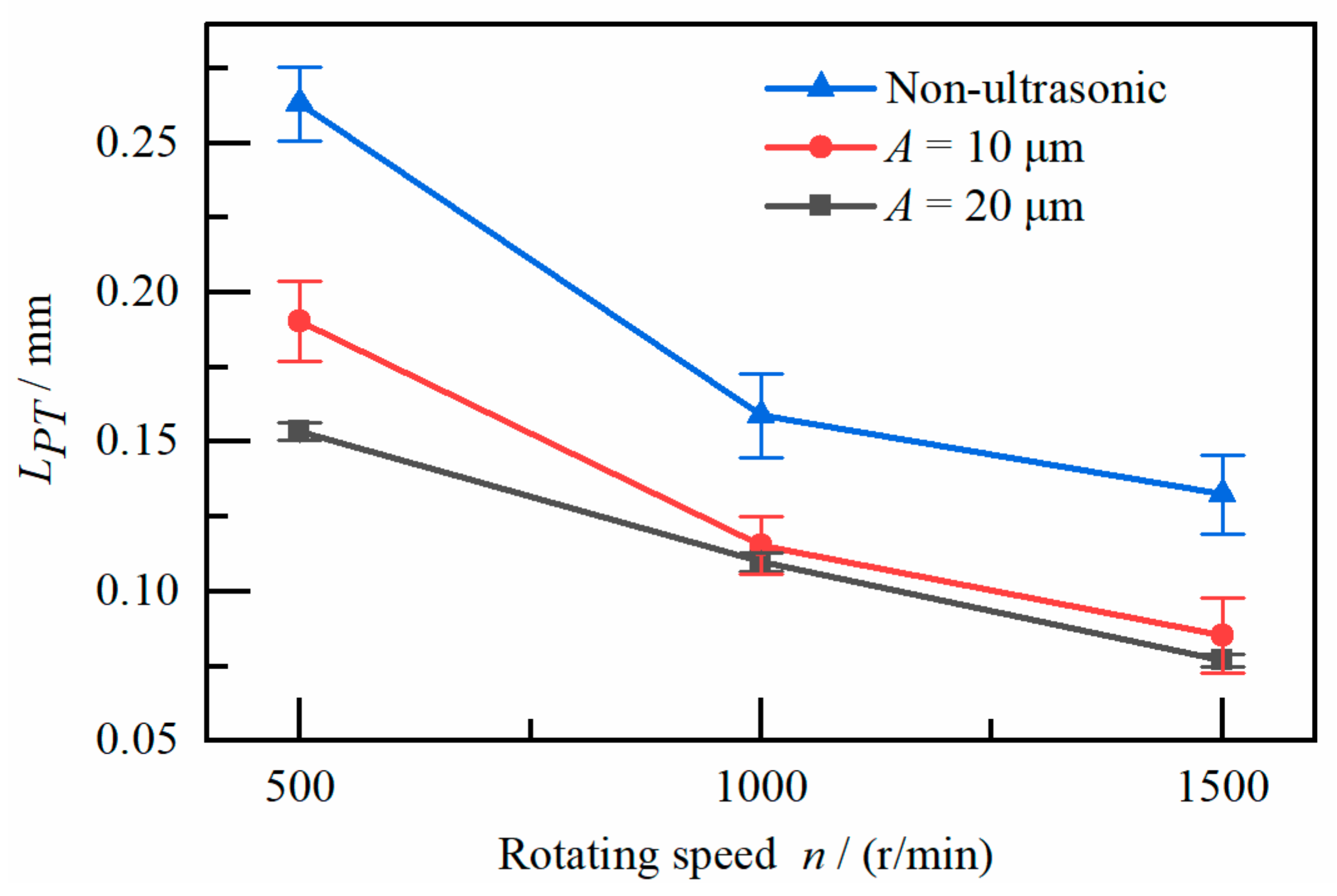
5.2.2. The Influence of Process Parameters on Trepanning Incision Quality
6. Conclusions
- (1)
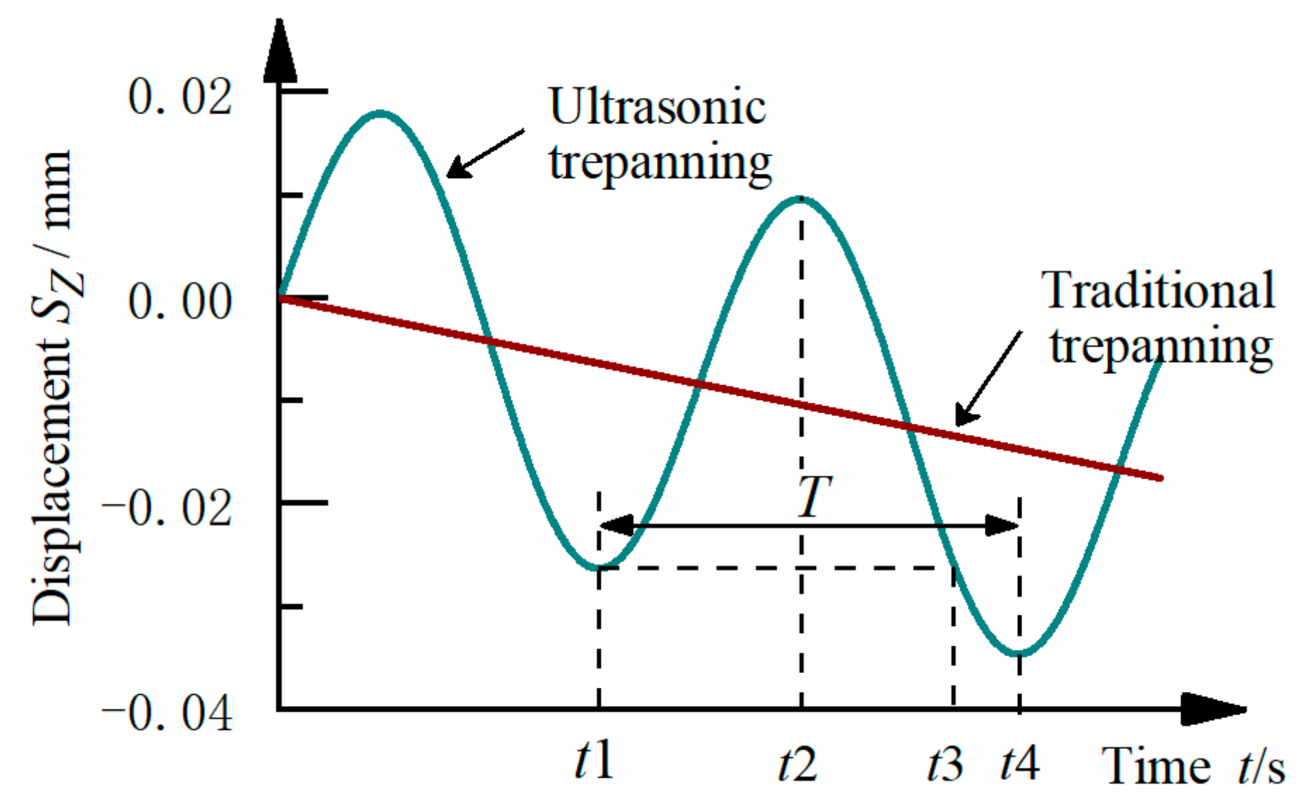
- Ultrasonic trepanning is a high-quality machining method for the vertical surface of the Nomex honeycomb core. The introduction of the ultrasonic vibration improves the quality of the trepanning incision significantly.
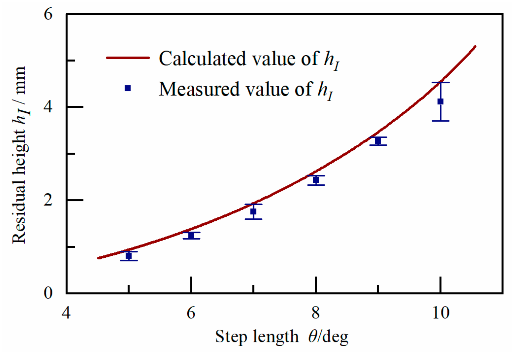
- (2)
- The trepanning dimensional error of the vertical surface is influenced by the tool size, step length and feature size of machined vertical surface. Moreover, the trepanning dimensional error experiment verifies that the theoretical value is consistent with the actual value, and the theoretical model can be used to predict the actual trepanning dimensional error.
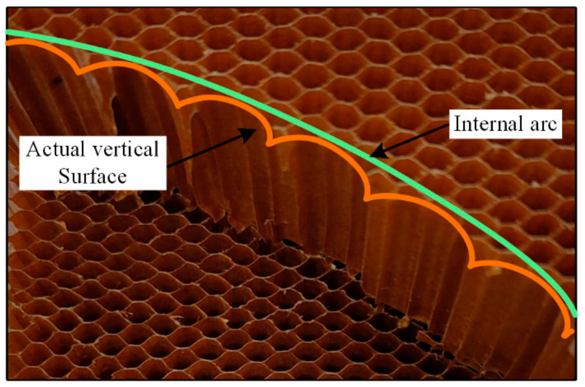
- (3)
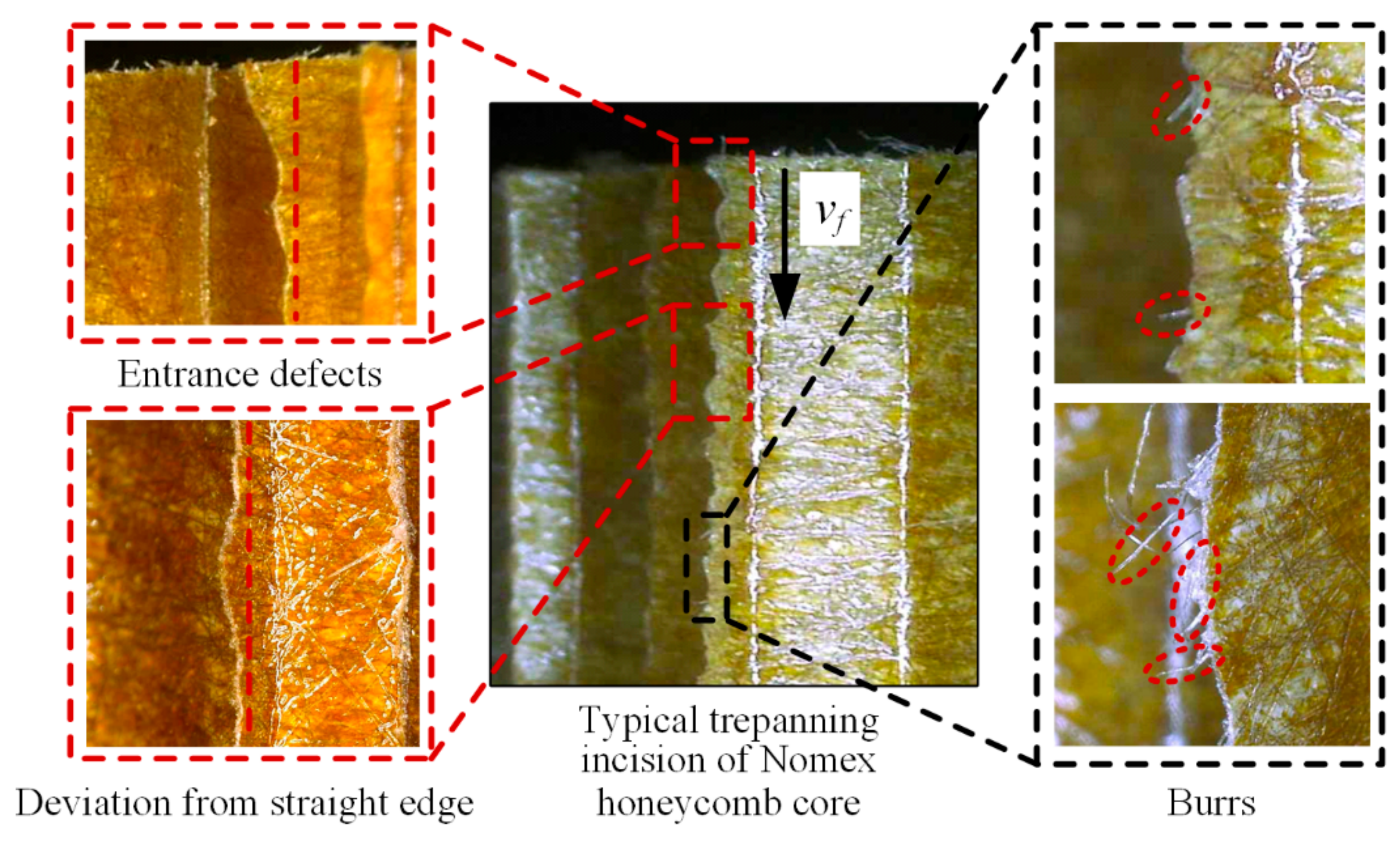
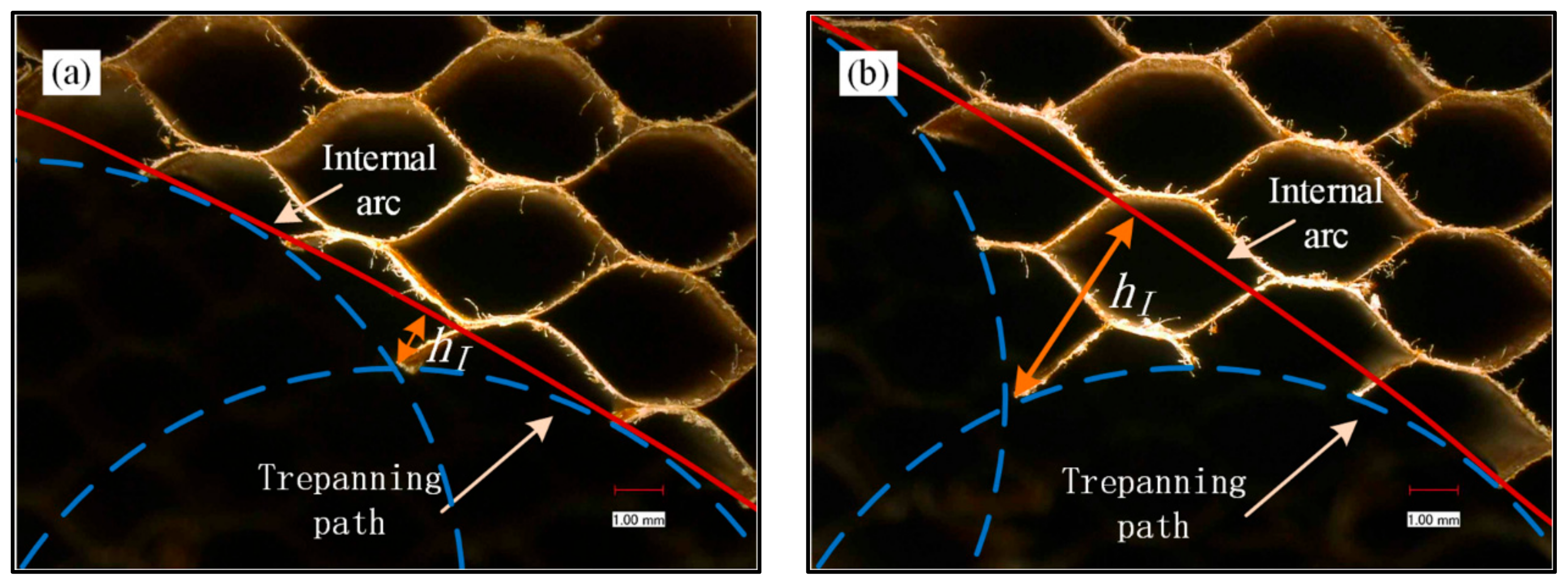
- The actual trepanning incision of the vertical surface is a curve incision with regular wavy characteristics. However, it can be found by comparison that the ultrasonic trepanning incision is straighter and there are no processing defects such as burrs.
- (4)
- The characteristic size of the actual wavy incision is used, as the evaluation parameter, to quantitatively analyze the quality of the trepanning incision. The quantitatively analytical result demonstrates that the quality of the ultrasonic trepanning incision with a vibration amplitude of 20 μm is optimized by about 40% on average, compared with traditional trepanning.
Author Contributions
Funding
Conflicts of Interest
References
- Foo, C.C.; Chai, G.B.; Seah, L.K. Mechanical properties of Nomex material and Nomex honeycomb structure. Compos. Struct. 2007, 80, 588–594. [Google Scholar] [CrossRef]
- Ahmad, S.; Zhang, J.; Feng, P.; Yu, D.; Wu, Z.; Ma, K. Processing technologies for Nomex honeycomb composites (NHCs): A critical review. Compos. Struct. 2020, 250, 112545. [Google Scholar] [CrossRef]
- Roy, R.; Park, S.-J.; Kweon, J.-H.; Choi, J.-H. Characterization of Nomex honeycomb core constituent material mechanical properties. Compos. Struct. 2014, 117, 255–266. [Google Scholar] [CrossRef]
- Liu, Y.; Liu, W.; Gao, W. Out-of-plane shear property analysis of Nomex honeycomb sandwich structure. J. Reinf. Plast. Compos. 2020, 620760328. [Google Scholar] [CrossRef]
- Li, W.; Qiu, C.; Li, Z.; Nie, H. A failure criterion for honeycomb structures considering the onset of instability under out-of-plane loads. J. Sandw. Struct. Mater. 2020, 425586206. [Google Scholar] [CrossRef]
- Karakoç, A.; Freund, J. Experimental studies on mechanical properties of cellular structures using Nomex® honeycomb cores. Compos. Struct. 2012, 94, 2017–2024. [Google Scholar] [CrossRef]
- Xie, S.; Feng, Z.; Zhou, H.; Wang, D.; Ma, W. In-plane and out-of-plane compressive mechanical properties of Nomex honeycombs and their prediction. J. Braz. Soc. Mech. Sci. Eng. 2020, 42, 1–20. [Google Scholar] [CrossRef]
- Jaafar, M.; Atlati, S.; Makich, H.; Nouari, M.; Moufki, A.; Julliere, B. A 3D FE modeling of machining process of Nomex® honeycomb core: Influence of the cell structure behaviour and specific tool geometry. Procedia CIRP 2017, 58, 505–510. [Google Scholar] [CrossRef]
- Gill, D.D.; Yip-Hoi, D.; Meaker, M.; Boni, T.; Eggeman, E.L.; Brennan, A.M.; Anderson, A. Studying the mechanisms of high rates of tool wear in the machining of aramid honeycomb composites. Volume 2: Additive Manufacturing; Materials. In Proceedings of the ASME 2017 12th International Manufacturing Science and Engineering Conference collocated with the JSME/ASME 2017 6th International Conference on Materials and Processing, Los Angeles, CA, USA, 4–8 June 2017; Volume 2. [Google Scholar]
- Zhang, J.; Tian, W. Selection of NC cutting tool for carbon fiber/Kevlar fiber/honeycomb core part. Aeronaut. Manuf. Technol. 2010, 71–73. [Google Scholar] [CrossRef]
- Hu, X.; Yu, B.; Li, X.; Chen, N. Research on cutting force model of triangular blade for ultrasonic assisted cutting honeycomb composites. Procedia CIRP 2017, 66, 159–163. [Google Scholar] [CrossRef]
- Kang, D.; Zou, P.; Wu, H.; Duan, J.; Wang, W. Study on ultrasonic vibration–assisted cutting of Nomex honeycomb cores. Int. J. Adv. Manuf. Technol. 2019, 104, 979–992. [Google Scholar] [CrossRef]
- Sun, J.; Dong, Z.; Wang, X.; Wang, Y.; Qin, Y.; Kang, R. Simulation and experimental study of ultrasonic cutting for aluminum honeycomb by disc cutter. Ultrasonics 2020, 103, 106102. [Google Scholar] [CrossRef] [PubMed]
- Wang, Y.; Wang, X.; Kang, R.; Sun, J.; Jia, Z.; Dong, Z. Analysis of influence on ultrasonic-assisted cutting force of Nomex honeycomb core material with straight knife. Chin. J. Mech. Eng. 2017, 53, 73–82. [Google Scholar] [CrossRef]
- Cao, W.; Zha, J.; Chen, Y. Cutting force prediction and experiment verification of paper honeycomb materials by ultrasonic vibration-assisted machining. Appl. Sci. 2020, 10, 4676. [Google Scholar] [CrossRef]
- Zhang, X.; Dong, Z.; Wang, Y.; Xu, Z.; Song, H.; Kang, R. Charization of surface microscopic of Nomex honeycomb after ultrasonic assisted cutting. J. Mech. Eng. 2007, 53, 90–99. [Google Scholar] [CrossRef]
- Xiang, D.; Wu, B.; Yao, Y.; Liu, Z.; Feng, H. Ultrasonic longitudinal-torsional vibration-assisted cutting of Nomex® honey-comb-core composites. Int. J. Adv. Manuf. Technol. 2019, 100, 1521–1530. [Google Scholar] [CrossRef]
- Toboła, D.; Morgiel, J.; Maj, Ł. TEM analysis of surface layer of Ti-6Al-4V ELI alloy after slide burnishing and low-temperature gas nitriding. Appl. Surf. Sci. 2020, 515, 145942. [Google Scholar] [CrossRef]
- Han, X.; Zhang, Z.; Hou, J.; Barber, G.C.; Qiu, F. Tribological behavior of shot peened/austempered AISI 5160 steel. Tribol. Int. 2020, 145, 106197. [Google Scholar] [CrossRef]
- Kalisz, J.; Żak, K.; Wojciechowski, S.; Gupta, M.; Krolczyk, G. Technological and tribological aspects of milling-burnishing process of complex surfaces. Tribol. Int. 2020, 106770. [Google Scholar] [CrossRef]
- Li, X.; Ren, J.; Tang, K.; Zhou, Y. A tracking-based numerical algorithm for efficiently constructing the feasible space of tool axis of a conical ball-end cutter in five-axis machining. Comput. Aided Des. 2019, 117, 102756. [Google Scholar] [CrossRef]
- Feng, P.; Wang, J.; Zhang, J.; Zheng, J. Drilling induced tearing defects in rotary ultrasonic machining of C/SiC composites. Ceram. Int. 2017, 43, 791–799. [Google Scholar] [CrossRef]
- Lin, Z. Principle and Design of Ultrasonic Horn; Science Press: Beijing, China, 1987. [Google Scholar]
- Xia, Y.; Zhang, J.; Wu, Z.; Feng, P.; Yu, D. Study on the design of cutting disc in ultrasonic-assisted machining of honeycomb composites. IOP Conf. Ser. Mater. Sci. Eng. 2019, 611, 012032. [Google Scholar] [CrossRef]
- Ahmad, S.; Zhang, J.; Feng, P.; Yu, D.; Wu, Z.; Ke, M. Research on Design and FE Simulations of Novel Ultrasonic Circular Saw Blade (UCSB) Cutting Tools for Rotary Ultrasonic Machining of Nomex Honeycomb Composites; Institute of Electrical and Electronics Engineers (IEEE): New York, NY, USA, 2019; pp. 113–119. [Google Scholar]
- Junichiro, K. Precision Machining and Vibration Assisted Cutting (Base and Application); China Machine Press: Beijing, China, 1985. [Google Scholar]


| Material | Elastic Modulus | Density | Poisson’s Ratio |
|---|---|---|---|
| (GPa) | (Kg/m3) | ||
| W9Mo3Cr4V | 221.9 | 7930 | 0.3 |
| Radius of Internal Arc | Step Length | Rotating Speed | Feed Rate |
|---|---|---|---|
| R /mm | θ/deg | n/(r/min) | vf/(mm/min) |
| 100 | 5, 6, 7, 8, 9, 10 | 1500 | 500 |
| Number | Ultrasonic Amplitude | Rotating Speed | Feed Rate |
|---|---|---|---|
| A/μm | n/(r/min) | vf/(mm/min) | |
| 1 | Non-ultrasonic | 500 | 2000 |
| 2 | 1000 | 2000 | |
| 3 | 1500 | 2000 | |
| 4 | 1500 | 1000 | |
| 5 | 1500 | 3000 | |
| 6 | 10 | 500 | 2000 |
| 7 | 1000 | 2000 | |
| 8 | 1500 | 2000 | |
| 9 | 1500 | 1000 | |
| 10 | 1500 | 3000 | |
| 11 | 20 | 500 | 2000 |
| 12 | 1000 | 2000 | |
| 13 | 1500 | 2000 | |
| 14 | 1500 | 1000 | |
| 15 | 1500 | 3000 |
Publisher’s Note: MDPI stays neutral with regard to jurisdictional claims in published maps and institutional affiliations. |
© 2020 by the authors. Licensee MDPI, Basel, Switzerland. This article is an open access article distributed under the terms and conditions of the Creative Commons Attribution (CC BY) license (http://creativecommons.org/licenses/by/4.0/).
Share and Cite
Sun, D.; Kang, R.; Wang, Y.; Guo, J.; Dong, Z. A Novel Ultrasonic Trepanning Method for Nomex Honeycomb Core. Appl. Sci. 2021, 11, 354. https://doi.org/10.3390/app11010354
Sun D, Kang R, Wang Y, Guo J, Dong Z. A Novel Ultrasonic Trepanning Method for Nomex Honeycomb Core. Applied Sciences. 2021; 11(1):354. https://doi.org/10.3390/app11010354
Chicago/Turabian StyleSun, Dingyi, Renke Kang, Yidan Wang, Jialin Guo, and Zhigang Dong. 2021. "A Novel Ultrasonic Trepanning Method for Nomex Honeycomb Core" Applied Sciences 11, no. 1: 354. https://doi.org/10.3390/app11010354
APA StyleSun, D., Kang, R., Wang, Y., Guo, J., & Dong, Z. (2021). A Novel Ultrasonic Trepanning Method for Nomex Honeycomb Core. Applied Sciences, 11(1), 354. https://doi.org/10.3390/app11010354