Review

Optical Fiber Current Sensors Based on FBG and Magnetostrictive Composite Materials

1
School of Mechatronic Engineering, China University of Mining and Technology, Xuzhou 221116, China
2
Jiangsu Engineering Technology Research Center on Intelligent Equipment for Fully Mining and Excavating, China University of Mining and Technology, Xuzhou 221008, China
3
National Rail Transit Electrification and Automation Engineering Technique Research Center, Chengdu 610031, China
4
National Institute of Metrology (NIM), Beijing 100029, China
5
School of Mechatronic Engineering, Xuzhou College of Industrial Technology, Xuzhou 221116, China
6
School of Information and Control Engineering, China University of Mining and Technology, Xuzhou 221116, China
*
Author to whom correspondence should be addressed.
Appl. Sci. 2021, 11(1), 161; https://doi.org/10.3390/app11010161
Submission received: 4 December 2020 / Revised: 22 December 2020 / Accepted: 22 December 2020 / Published: 26 December 2020

Abstract

:
Optical fiber current sensors are widely used in the online monitoring of a new generation power system because of their high electrical insulation, wide dynamic range, and strong anti-electromagnetic interference ability. Current sensors, based on fiber Bragg grating (FBG) and giant magnetostrictive material, have the advantages of high reliability of FBG and high magnetostrictive coefficient of giant magnetostrictive material, which can meet the monitoring requirements of digital power systems. However, giant magnetostrictive materials are expensive, fragile, and difficult to mold, so giant magnetostrictive composite materials have replaced giant magnetostrictive materials as the sensitive elements of sensors. High sensitivity, high precision, wide working range, low response time, and low-cost optical fiber current sensors based on magnetostrictive composites have become a research hotspot. In this paper, the working principle of the sensor, the structure of the sensor, and the improvement of magnetostrictive composite materials are mainly discussed. At the same time, this paper points out improvements for the sensor.

1. Introduction

With the rapid development of intelligent power grid technology, optical fiber current sensors play an important role in power measurement, monitoring, and protection. Optical fiber current sensors have the following inherent characteristics: anti-electromagnetic interference, electrical isolation, small size, and light weigh. At the same time, the measurement object of the optical fiber current sensor is a magnetic field generated by the current, not the current itself, which avoids the danger of high voltage measurement [1].
Optical fiber sensors are of particular interest for applications in high-voltage environments of the electric power industry [2]. At present, optical fiber current sensors reported in the literature mainly include Faraday magneto-optical effect, Rogowski coil photoelectric hybrid, and magnetostrictive effect combined with optical fiber. In the current sensor based on Faraday magneto-optical effect, accuracy problems caused by linear birefringence in optical fiber, the verdet constant drift caused by temperature, and aging problems of the sensor head have always been the biggest obstacles to the practical application of this kind of current sensor; the Rogowski coil photoelectric hybrid current transformer is still affected by environmental electromagnetic field, high-voltage circuit current supply, and other factors in practical application; and the magnetostrictive current sensor has wide current response frequency band and high sensitivity, and can realize distributed measurement with the cooperation of demodulation instruments. The cost for synchronous monitoring of multi-point current is relatively low, and it has good industrial application prospects [3].
Giant magnetostrictive materials (GMM) have the advantages of small size, fast response speed, high precision, and easy integration [4]. Terfenol-D (TD) alloy is a new type of rare-earth giant magnetostrictive material, which has high magnetostrictive properties and is widely used as a sensitive element of the current sensor. However, Terfenol-D alloy is expensive, fragile, and difficult to form into a specific shape. This can be solved by combining TD particles with resin to form giant magnetostrictive powder composite (GMPC) [5]. Magnetostrictive composites also have other excellent properties, such as enhanced tensile strength and low eddy current loss. Preloading also can be reduced or even avoided due to the pre-stress generated during curing. In addition, because of the low content of magnetostrictive materials and a simplified process, the cost of composite materials is low; at the same time, the magnetostriction of magnetostrictive composites can compete with the magnetostrictive alloy.
Optical fiber current sensors based on magnetostrictive composite material have the advantages of high sensitivity, high precision, wide working range, low response time, and low cost. In this paper, the application of magnetostrictive composite materials in optical fiber current sensors is summarized, mainly from the working principle of the sensor, the structure of the sensor, and the modification of magnetostrictive composite materials. The structure of the sensor is mainly studied according to the shape of magnetostrictive composite material, the shape of the magnetic permeable material, and the number of permanent magnets. The improvement of magnetostrictive composites is mainly studied from aspects of particle volume fraction, binder type, particle size, orientation magnetic field, and molding pressure.

2. Working Principle of the Sensor

The proposed sensor is composed of a magnetic circuit sensing system and photoelectric testing system. The magnetic circuit sensing system is composed of magnetostrictive materials (magnetostrictive composite materials), fiber gratings, magnetically permeable materials, and permanent magnets. The photoelectric test system consists of a light source, a circulator, and a spectrum analyzer. The magnetostrictive material is combined with the fiber grating and placed in the magnetic field generated by the current, and the change of the current can be obtained by demodulating the wavelength drift of the fiber grating [6]. This paper studies the magnetostriction phenomenon and its causes, the working principle of fiber grating, and the role of permanent magnets.

2.1. Magnetic Circuit Sensing System

2.1.1. Magnetostrictive Material

Magnetostrictive materials extend (or shorten) in size under the action of external magnetic field, and then return to their original size after the external magnetic field is eliminated. This phenomenon is called magnetostriction. Since this phenomenon was first discovered by Joule in Ni materials, it is also called the Joule phenomenon or Joule effect [7]. Magnetostriction refers to geometric deformation caused by externally applied magnetic field [8]. The magnitude of magnetostriction is expressed by the magnetostriction coefficient λ = ΔL/L, where ΔL refers to the variation of material length and L refers to the overall length of material, as shown in Figure 1.
The causes of magnetostriction are shown in Figure 2 [9]. Magnetic materials can be divided into numerous magnetic domains microscopically. When external magnetic field intensity is 0, the magnetic moment directions of magnetic domains are different, but the vector sum is zero, and the magnetic moment of the whole object is zero, which indicates that the material is not magnetic in the macroscopic view, i.e., the material does not deform. When the magnetic domain is in an applied magnetic field, it will deviate from the original self-magnetization direction and deviate towards the direction of the applied magnetic field. When the magnetic domain deflects in the same direction, a magnetic field force will be generated in this direction, which will cause the ferromagnetic material to be deformed by the force in this direction, resulting in magnetostriction. Within a certain range, magnetostriction of ferromagnetic materials will increase with the increase of the applied magnetic field, but when the applied magnetic field exceeds a certain range, magnetostriction basically remains unchanged, i.e., the deformation (strain) of the material reaches saturation [10].

2.1.2. Fiber Bragg Grating

After cleaning the surface of the magnetostrictive material, the fiber Bragg grating (FBG) was bonded to the magnetostrictive material with cyanoacrylate adhesive. When the current generates a magnetic field, the magnetostrictive material in the magnetic field will be deformed, and the deformation will be transferred to the bonded FBG.
The function of FBG is essentially to form a narrowband (transmission or reflection) filter or mirror in the fiber core, as shown in Figure 3. When a beam of broad-spectrum light passes through the fiber grating, the wavelength meeting the Bragg condition of the FBG will be reflected, and other wavelengths will continue to transmit through the fiber grating. The formula of center wavelength is [11]:
λ B = 2 n e f f Λ
where Λ is the grating period, and neff is the effective refraction of FBG.
When the FBG is subjected to axial stress, it will be strained, and the period and refractive index of the FBG will change. At this time, the relationship between the central wavelength change of the FBG and the strain is as follows:
Δ λ B = λ B ( 1 P C ) ε
where Pc is the effective photo-elastic coefficient, which ε is about 0.22 for the silicon fiber medium.

2.1.3. Permanent Magnet

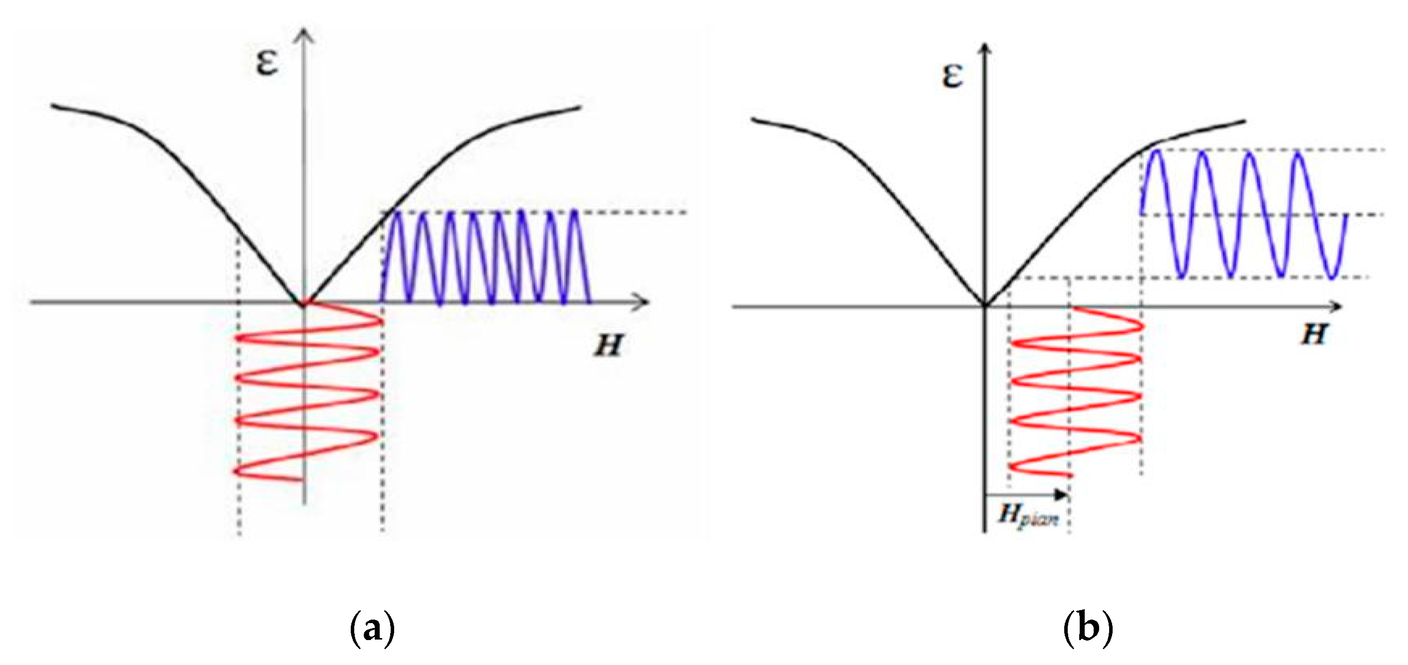
Magnetostrictive materials have unipolar characteristics, i.e., the expansion and contraction of magnetostrictive materials is only related to the magnitude of the applied magnetic field, but has nothing to do with its direction. When the applied magnetic field is an alternating magnetic field, although the directions of the positive and negative half-cycles are opposite, the expansion and contraction directions of magnetostrictive materials excited by the two half-cycles are the same. The unipolar characteristics of magnetostrictive materials make a frequency-doubling effect appear in the working process, as shown in Figure 4.
Permanent magnets are added to the magnetic circuit to provide a constant magnetic field. Under the action of a constant magnetic field, the total magnetic field applied to magnetostrictive materials is all positive or all negative. Therefore, the permanent magnet avoids the influence of the unipolar characteristics of magnetostrictive materials, and enables the sensor to obtain a complete alternating current (AC) cycle, as shown in Figure 5.

2.2. Optoelectronic Test System

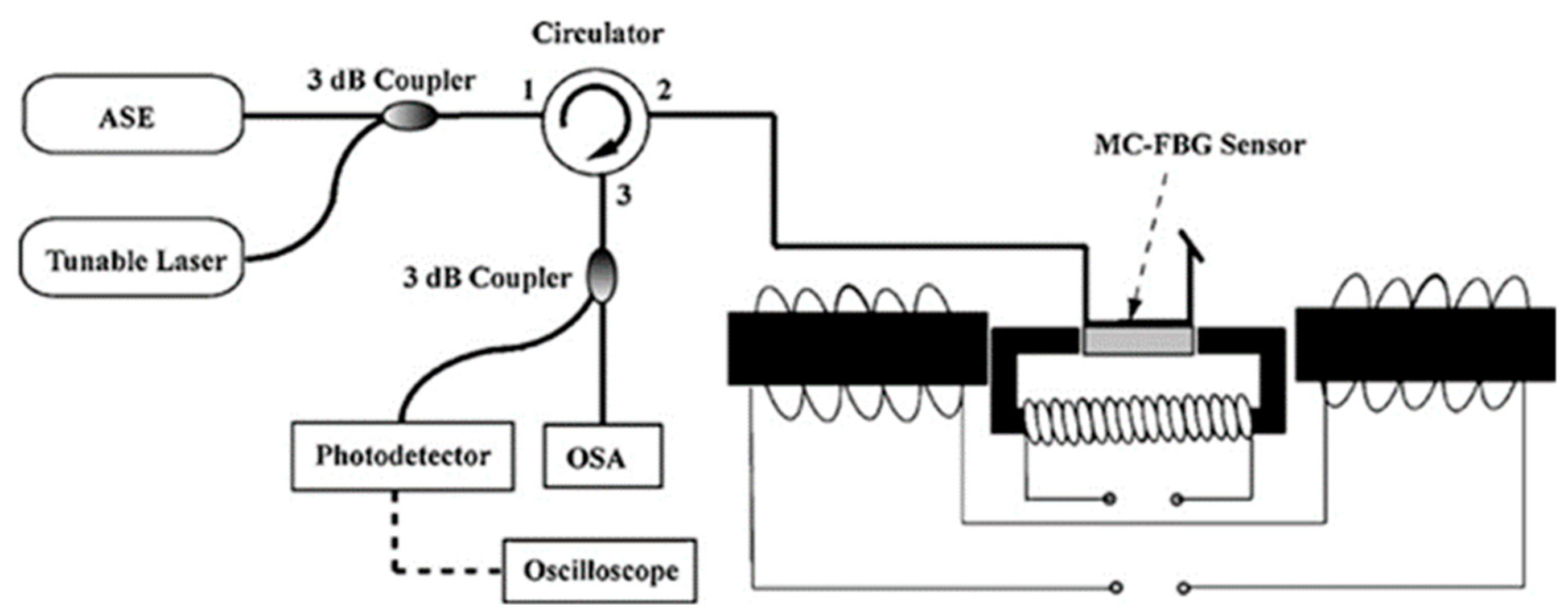
Figure 6 shows the experimental setup for evaluating the performance of the sensor. An AC-band amplified spontaneous emission (ASE) source or a tunable laser (Agilent 81640B), combined with a 3 dB coupler, was used to illuminate the MC-FBG sensor via ports 1 and 2 of an optical circulator. The reflected wavelengths via ports 2 and 3 of the optical circulator were split by a 3 dB coupler and then measured by a 125 MHz photodetector (NewFocus 1811) or an optical spectrum analyzer (OSA) (Agilent 86140A) with a 0.1 nm resolution. The electromagnet provides a quasi-static magnetic field with a maximum amplitude of 146 kA/m and a frequency of 1 Hz. The function of the spectrum analyzer is to demodulate and display signals [12].

3. Optical Fiber Current Sensor Based on Magnetostrictive Composite Materials

The performance indices of the sensor are sensitivity, linear working range, linearity, response time, and measurement accuracy. To improve the performance of the sensor and reduce the production cost of the sensor, this paper mainly studies the sensor from the following two aspects: the research of sensor structure, and the research of the magnetostrictive composite material.

3.1. Sensor Structure

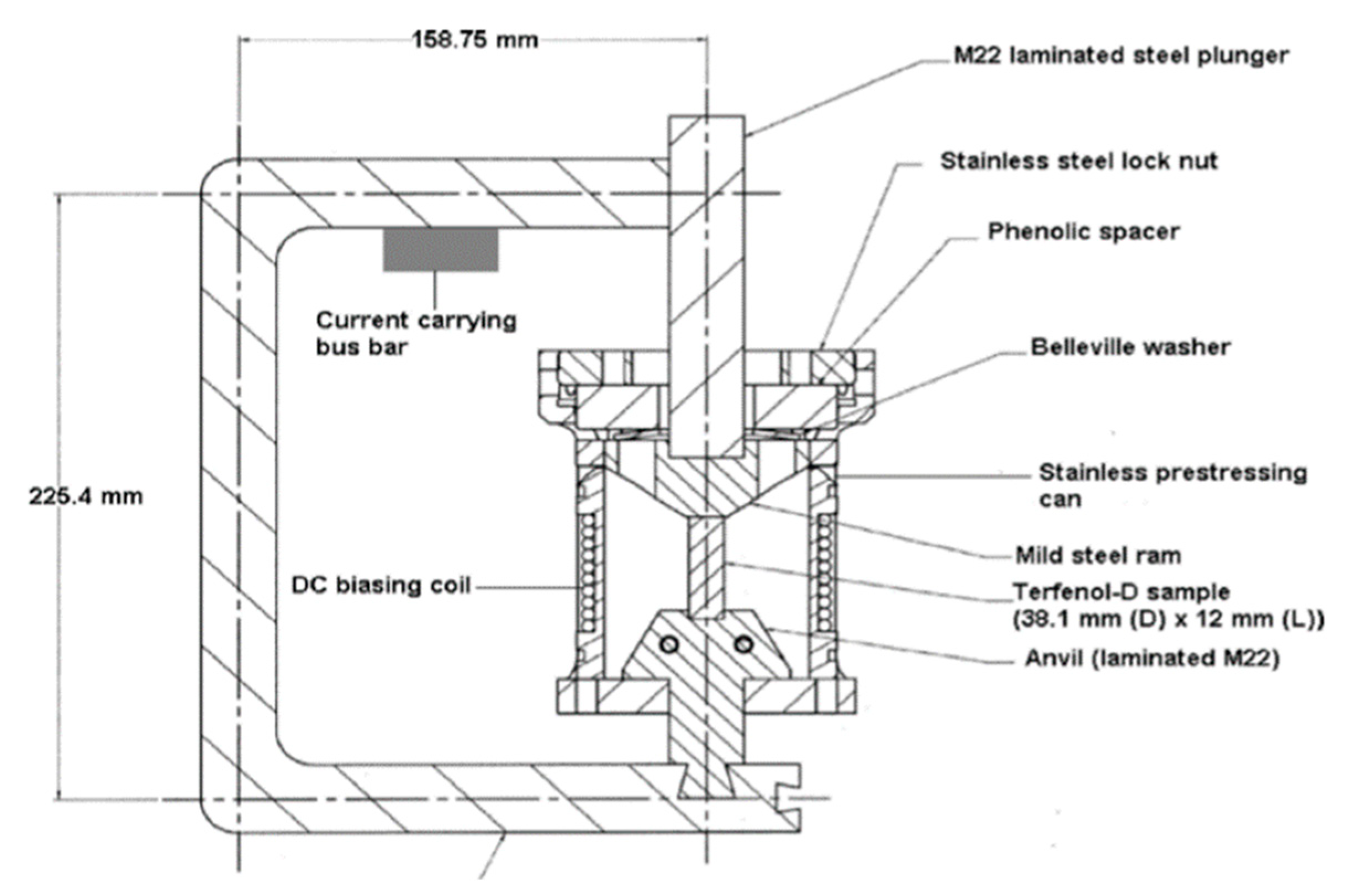
In 2005, Debashis Satpathi et al. [13] proposed an optical fiber current sensor based on magnetostrictive material. The proposed sensor uses 40 g cylindrical rod magnetostrictive material, as shown in Figure 7. Magnetostrictive materials have unipolar characteristics. To avoid the rectified output of the sensor, a direct current (DC) bias coil is introduced into the sensor. At the same time, mechanical devices are added to the sensor to provide preloading stress. It is found that the output of the sensor is non-linear when the preloading stress is low. When the preloading stress is high, the linearity of the sensor will increase. Although the mechanical device improves the linearity of the sensor, it also increases the complexity of the sensor structure, and the addition of a DC bias coil leads to the sensor being active.
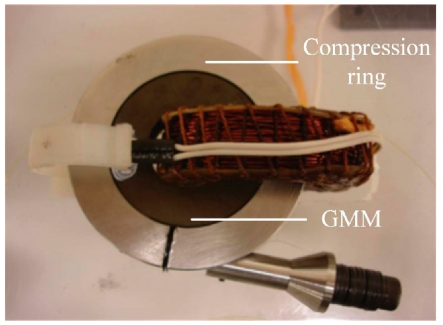
In 2013, Cremonezi et al. [14] proposed an optical fiber current sensor for measuring AC. The proposed sensor uses 144 g annular solid magnetostrictive material, as shown in Figure 8. The stainless-steel compression ring exerts a certain pressure on the magnetostrictive material, which makes the relationship between the strain produced by the magnetostrictive material and the applied magnetic field approximate to a quadratic function. At the same time, the linearity of the sensor is better, and the measurement error is smaller under the action of preloading stress. The proposed sensor has fast transient response, but the sensor does not introduce DC bias device, which leads to a frequency-doubling of the output of the sensor.
In 2015, Nazaré and Werneck [15] proposed a new and compact optical fiber current sensor. The new sensor is composed of 74 g solid rectangular magnetostrictive material, magnetic conductive material and permanent magnet, as shown in Figure 9. The magnetostrictive material is Terfenol-D alloy, the magnetic conductive material is made of ordinary ferrosilicon, and the permanent magnet is made of NdFeB. The purpose of adding permanent magnets to the magnetic circuit is to provide a certain constant magnetic field, so that the sensor can work in a linear region and obtain a complete AC cycle. The magnetic field acting on magnetostrictive material consists of an AC magnetic field generated by wire and a constant magnetic field generated by a permanent magnet. The author uses permanent magnets instead of DC drive coils, so the sensor is passive. Although the proposed new sensor eliminates the frequency-doubling phenomenon of magnetostrictive materials, it still does not solve the disadvantage of Terfenol-D alloy being expensive and fragile.
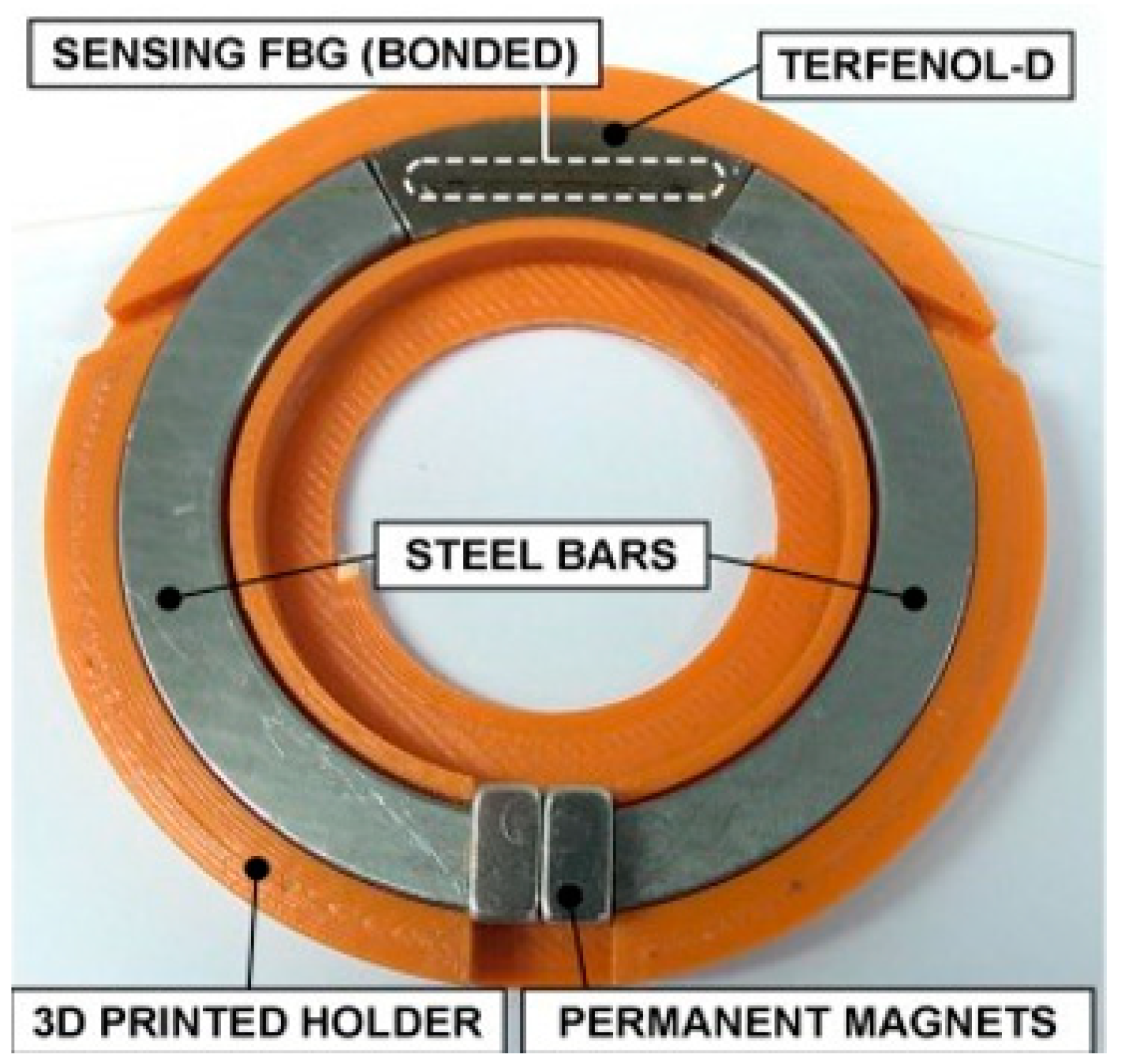
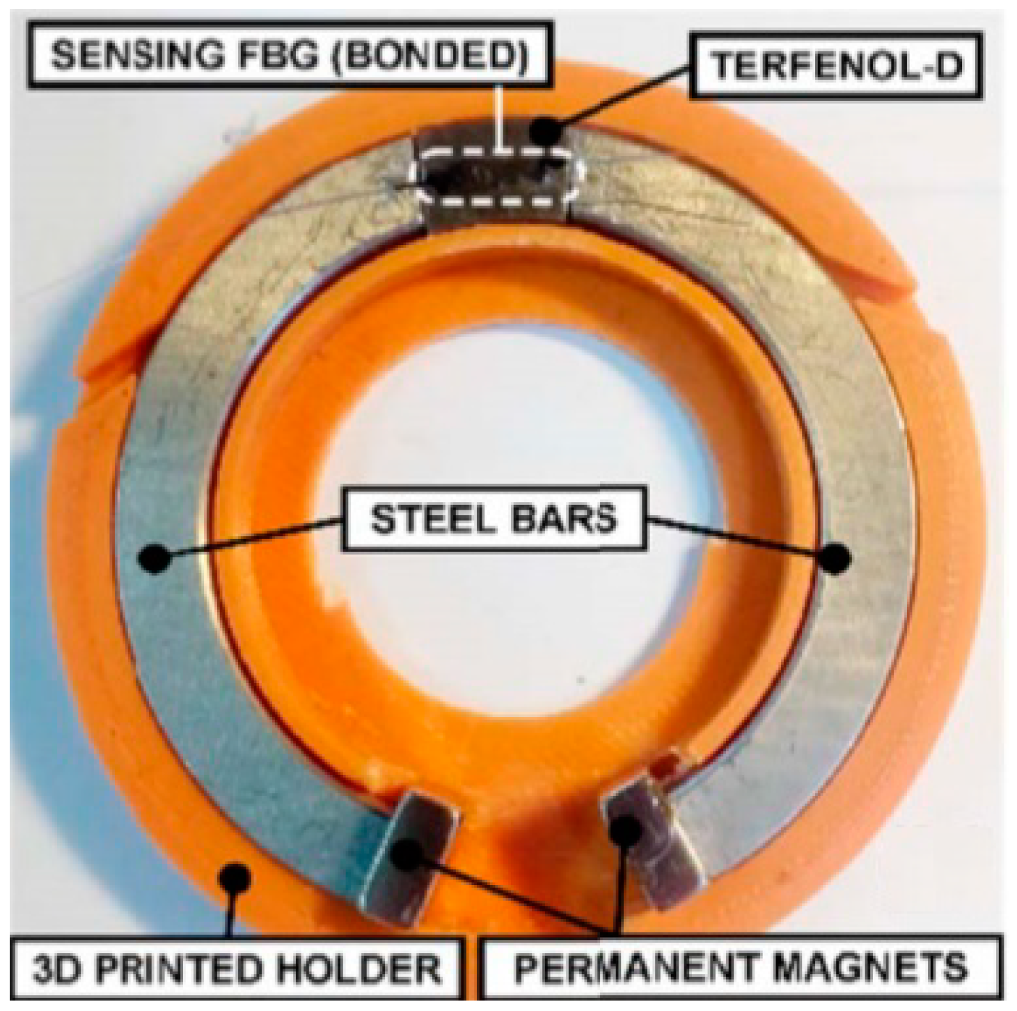
In 2019, Alex Dante et al. [16] proposed a new ring optical fiber current sensor based on magnetostrictive material. As shown in Figure 10, the proposed sensor is composed of magnetostrictive material, magnetically permeable material, and a permanent magnet. Iron bars (99.5% Fe, relative permeability 500) are introduced into the magnetic circuit, which not only reduces the mass of TD, but also increases the magnetic flux density per gram of TD. To reduce the mass of TD greatly, the author uses finite element simulation (FEM) to guide the structure design of the proposed optical fiber current sensor. Compared with the sensor based on annular magnetostrictive material, the shape of magnetostrictive material of the proposed sensor is 1/6 annular, the mass is only 5.6 g, and the sensitivity is higher. The structure proposed by the author not only reduces the consumption of TD and the cost of the sensor, but also improves the sensitivity of the sensor. However, TD still has the disadvantage that it is difficult to form.
Subsequently, Alex Dante et al. [17] proposed an optical fiber current sensor based on low-quality magnetostrictive materials, as shown in Figure 11. The cost of the proposed sensor is further reduced, and only 2.0 g of Terfenol-D alloy is used. The finite element simulation shows that the magnetic flux density of FBG attached to the fiber-optic current sensor based on 2.0 g magnetostrictive material is significantly increased compared with the fiber-optic current sensor based on 5.6 g magnetostrictive material. The sensitivity of the optical fiber current sensor based on 2.0 g magnetostrictive material is twice that of the optical fiber current sensor based on 5.6 g magnetostrictive material, and the measurement error of both is less than 3%. Transient response test shows that there is no obvious delay between the input and output signals of the sensor, which indicates that the sensor is suitable for fault detection.
Lopez et al. [18] proposed an optical fiber current sensor based on hyperboloid magnetostrictive composite material, and the proposed that the sensor only uses 1.5 g of Terfenol-D alloy. The sensor adopts an open-loop structure, which can not only reduce the use of magnetically permeable materials, but also allow convenient installation of the sensor. TD alloy is the main magnetostrictive material. Because TD alloy is expensive, fragile and difficult to form, magnetostrictive composite material is used instead of magnetostrictive material. Magnetostrictive composite material is composed of TD alloy powder and epoxy resin. FBG embedded in magnetostrictive composite allows the sensor to have a frequency response of 60 kHz. As shown in Figure 12, the shape of magnetostrictive composite is hyperboloid, which not only reduces the use of TD alloy, but also improves the sensitivity of the sensor. When the input signal produces a current step of 150 A, the response time of the sensor is only 1.5 ms. The sensor based on hyperboloid magnetostrictive composite material not only reduces the production cost and improves the sensitivity of the sensor, but also reduces the response time of the sensor.
Lopez et al. [19] proposed an optical fiber current sensor with concentrated magnetic flux density based on magnetostrictive composite material, and the mass of Terfenol-D alloy used in the proposed sensor was only 0.42 g. The author uses FEM to optimize the geometry of the optical fiber current sensor. As shown in Figure 13, the structure of the magnetically permeable material is arranged in a ring structure from thick to thin, which not only reduces the usage amount of the magnetically permeable material, but also makes the magnetic flux density on the magnetic field telescopic composite material more concentrated. The author studied the number of different permanent magnets and found that when the number of permanent magnets is 5, the maximum non-linear error of the sensor is only 0.15%. The proposed sensor not only reduces the production cost and improves the sensitivity, but also reduces the maximum non-linear error of the sensor. As shown in Table 1, several kinds of current sensors based on FBG for high-voltage lines are compared in this paper.
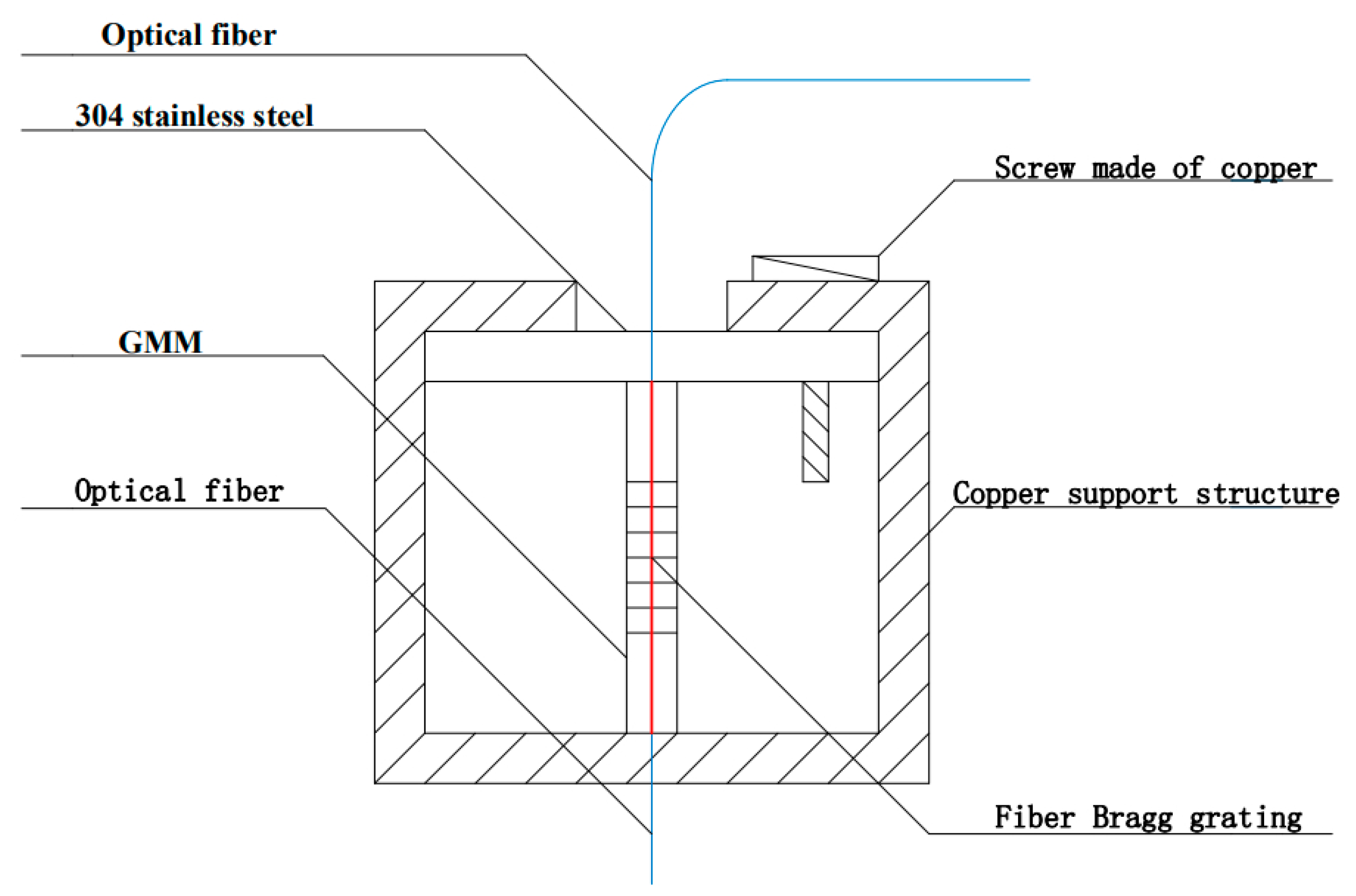
Wang et al. [20] proposed a fiber grating current sensor with enhanced sensitivity based on giant magnetostrictive material. When subjected to preloading stress, GMM sensitivity to magnetic field increases significantly. According to this characteristic, the beam is added to the conventional rectangular GMM to bear the applied pressure, thus forming a T-shaped structure, as shown in Figure 14. The material of the beam is 304 stainless-steel. A T-shaped structure is placed in a copper support structure. A special copper screw is placed at the upper right of the structure, and the beam of the T-shaped structure is pressurized by the screw, so as to achieve the purpose of pressurizing the T-shaped structure. Therefore, the sensitivity enhanced current sensor is composed of GMM, FBG, copper support structure, and screws made of copper. Experiments show that the sensitivity of the sensor is significantly improved, and the cost of the proposed structure is low. As shown in Table 2, current sensors with different structures are summarized in this paper.

3.2. Magnetostrictive Composites

The performance of magnetostrictive composites directly affects the performance of sensors, so it is necessary to study magnetostrictive composites. There are two main preparation methods of magnetostrictive composites, namely powder sintering method and powder bonding method. Powder sintering method refers to grinding magnetostrictive alloy into powder under a vacuum or under the protection of rare gas, pressing and molding in a mold after drying, and finally sintering under the protection of inert gas [21,22]. The bonding method breaks the magnetostrictive alloy into powder by a proper method, then mixes the powder with the selected binder evenly in proportion, pressing, extruding or injecting in a magnetic field and finally solidifying at a specific temperature [23].
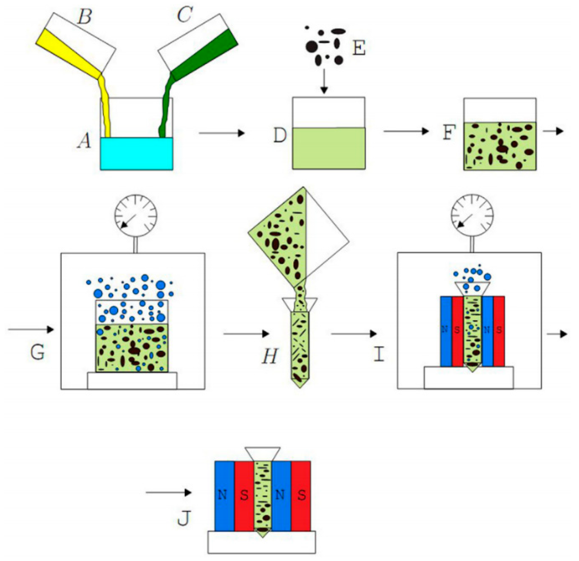
Kaleta et al. [24] studied the effects of orientation magnetic field and pre-compression stress on magnetostrictive composites. The author prepared the composite material with 70% particle volume fraction, as shown in Figure 15 for the specific process of preparing the composite material: First, epoxy resin and curing agent are mixed according to a certain proportion, then a certain amount of TD particles are added, then the mixture is fully stirred and degassed in vacuum, then the mixture is poured into a mold, and finally the mold is placed in a magnetic field to wait for curing. When the pre-compression stress and the orientation of the magnetic field intensity are the same, the magnetostriction value of composites with vertical orientation magnetic field direction is greater than that of composites with parallel orientation magnetic field direction. At the same time, with the same orientation magnetic field, when the pre-compression stress is from 0 to 9 MPa, the magnetostrictive value of the composite material gradually increases with the increase of pre-compression stress. When the pre-compression stress reaches 9 MPa, the composite material obtains the highest magnetostriction value.
Quintero et al. [25] studied the effects of TD particle size, particle volume fraction, binder type, and pre-compression stress on magnetostrictive composites. As shown in Figure 16, the fiber grating is embedded in the magnetostrictive composite material. When the particle volume fraction is 10%, 20%, and 30%, the magnetization of the composites with 30% particle volume fraction is the highest. When the binder is epoxy resin and polyurethane resin, respectively, the magnetization of the composite with epoxy resin as binder is the highest. The author classified the particle size into < 50 μm, 74–150 μm and > 200 μm, among which the magnetization of the composites was the highest when the particle size was > 200 μm. Although the sensitivity of the composite material is lower than that of the monolithic alloy, the sensitivity and linear range of the sensor are increased by 40% and 20%, respectively, by applying 8.6 MPa preloading stress.
Xuan Zhao et al. [26] studied the effects of magnetic field orientation and rare-earth elements on magnetostrictive composites. The author prepared two samples of the same composite material, one cured without applying orientation magnetic field, the other cured with orientation magnetic field. It is found that the magnetostriction of composites with orientation magnetic field is more than 4 times that of composites without orientation magnetic field. At the same time, it is found that the magnetostriction of the composites doped with rare-earth element Y is obviously higher than that of the composites undoped with rare-earth element Y.
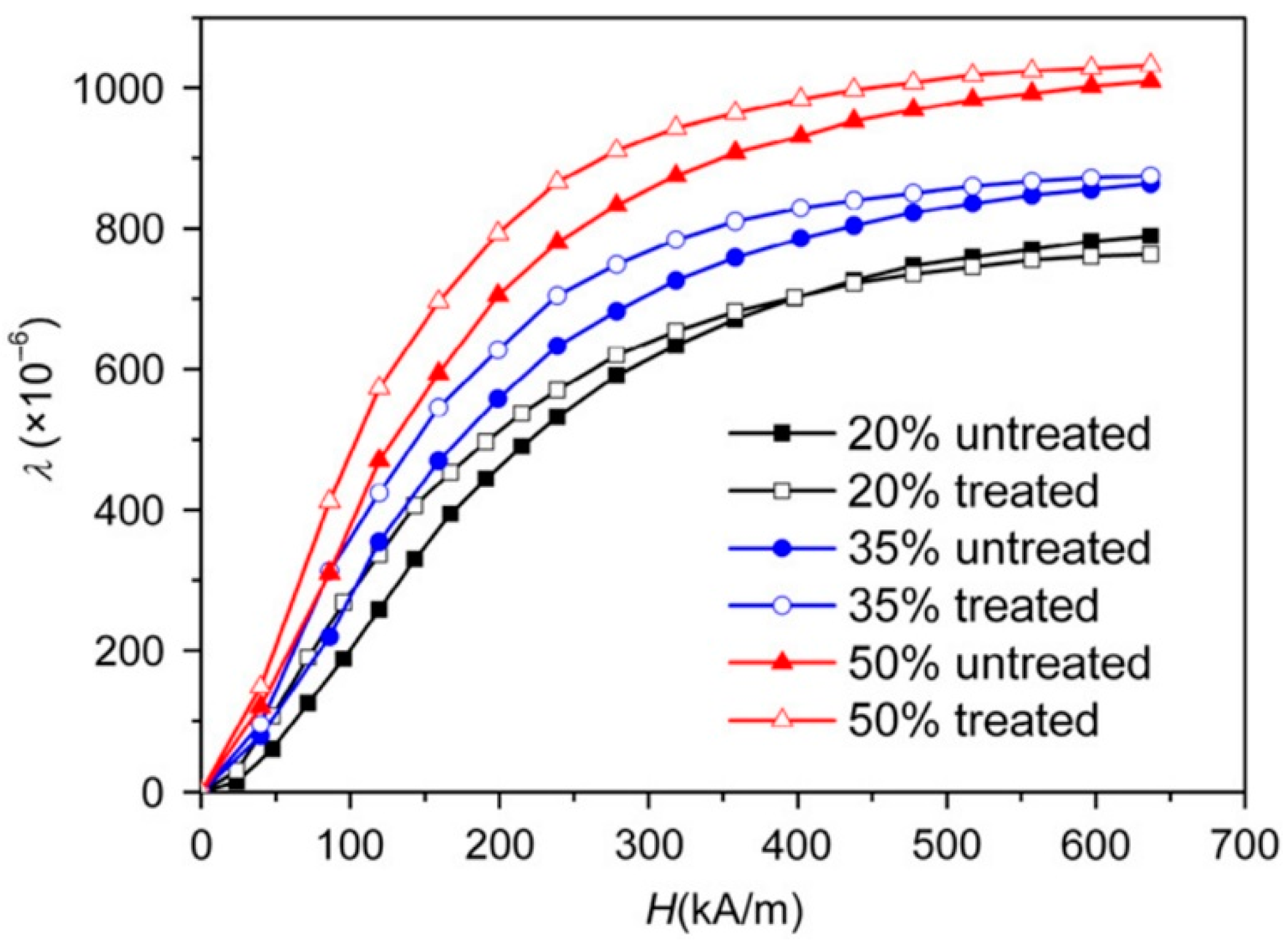
Xufeng Dong et al. [27] studied the effect of titanate coupling agent on magnetostrictive composites. Because the bonding strength between resin and TD particles will affect the properties of magnetostrictive composites, the author treated TD particles with titanate coupling agent to improve the bonding strength. As shown in Figure 17, when the particle volume fraction is the same, the magnetostriction of the magnetostrictive composite material treated with coupling agent is higher than that of the magnetostrictive composite material without coupling agent treatment. However, the saturation magnetostriction of the two magnetostrictive composites is almost the same. At the same time, the author found that the magnetostrictive composite treated by coupling agent has faster response time, which is beneficial to improve the performance of the sensor.
Xufeng Dong et al. [28] studied the optimum orientation magnetic field strength of magnetostrictive composites with different particle volume fractions. Magnetostrictive composites with TD particle volume fraction of 20%, 30%, and 50% were prepared. For magnetostrictive composites with particle volume fraction of 20%, when the orientation magnetic field intensity is from 0 to 30 kA/m, the saturation magnetostriction of composites increases with the increase of orientation magnetic field intensity; when the orientation magnetic field strength is greater than 30 kA/m, it is almost unchanged. Therefore, for the composite with 20% particle volume fraction, the best orientation magnetic field strength is 30 kA/m. Similarly, for composites with 30% and 50% particle volume fraction, the best orientation magnetic field strength is 80 kA/m and 100 kA/m, respectively.
Bochen Li et al. [29] studied the effects of preloading stress and particle volume fraction on magnetostrictive composites. As shown in Figure 18, the author compares the relationship between magnetostriction and applied magnetic field of composites with different particle volume fractions when the pre-compression stress is 0 MPa and 10 MPa, respectively. As shown in the figure, when the pre-compression stress is the same, within a certain range of particle volume fraction, the larger the particle volume fraction, the greater the magnetostriction of the composite material. When the volume fraction of particles is 57%, the magnetostriction of the composites is maximum. At the same time, when the volume fraction of particles is the same, the magnetostriction of composites with pre-compression stress of 10 MPa is greater than that of composites with pre-compression stress of 0 MPa.
Tomiczek et al. [30,31] studied the effects of TD particle size, particle volume fraction, and preloading stress on composites. Two kinds of samples with different particle size distribution, namely powder A with particle size of 38–106 μm and powder B with particle size of 106–212 μm, were manufactured by the author. It is found that when the pre-compression stress and particle volume fraction are the same, the magnetostriction of magnetostrictive composites is the largest when the particle size is 106–212 μm. When the particle size and volume fraction are the same, the magnetostriction of magnetostrictive composites is the largest when the pre-compression stress is 2 MPa. At the same time, when the pre-compression stress and particle size are the same, the magnetostriction of magnetostrictive composites with 20% particle volume fraction is the largest.
Tian Jianjun et al. [32] studied the effects of orientation magnetic field, particle size, and molding pressure on magnetostrictive composites. The author sifted the powder into three grades (below 50 μm, 50–80 μm, and 80–100 μm). When the particle size is 50–80 μm, the magnetostriction of magnetostrictive composites is the largest. It is found that when the applied magnetic field is higher than 3 kA/m, the magnetostriction of composites with orientation magnetic field is higher than that of composites without orientation magnetic field. In this paper, Cold Isostatic Pressing (CIP) of 200 MPa was used to recompress the composite, and the density of the composite increased from 6.84 g/cm3 to 7.24 g/cm3. Under the same conditions, the magnetostriction of the composites after CIP treatment is obviously higher than that of the composites without CIP treatment.
Jia Ao et al. [33] studied the effects of TD particle size, particle mass fraction, and molding pressure on magnetostrictive composites. Magnetostrictive composites with particle mass fraction of 85%, 90% and 93% were prepared by the authors, and the maximum magnetostriction of the composites was obtained when the particle mass fraction was 90%. This is because when the mass fraction of particles is low, the distance between TD particles is large, and the resin hinders the transmission of magnetostriction; When the mass fraction of particles is high, TD particles are prone to cluster phenomenon; Therefore, the overall magnetostriction of the composite material is small. Then, the author sifted TD particles into 0–74 μm, 74–150 μm and 150–300 μm. It is found that GMPC has good magnetostrictive properties when the particle size is 74–150 μm and 150–300 μm. This is because fine alloy particles have large specific surface area and are easy to oxidize, which is not conducive to the properties of composite materials. At the same time, the author compares the relationship between magnetostriction and magnetic field strength of GMPC at molding pressures of 200 MPa, 300 MPa, and 450 MPa, respectively. However, with the increase of molding pressure, the magnetostriction of GMPC increases only slightly. This shows that when the molding pressure is 200 MPa, the compact bonding between alloy particles and binder is basically realized.
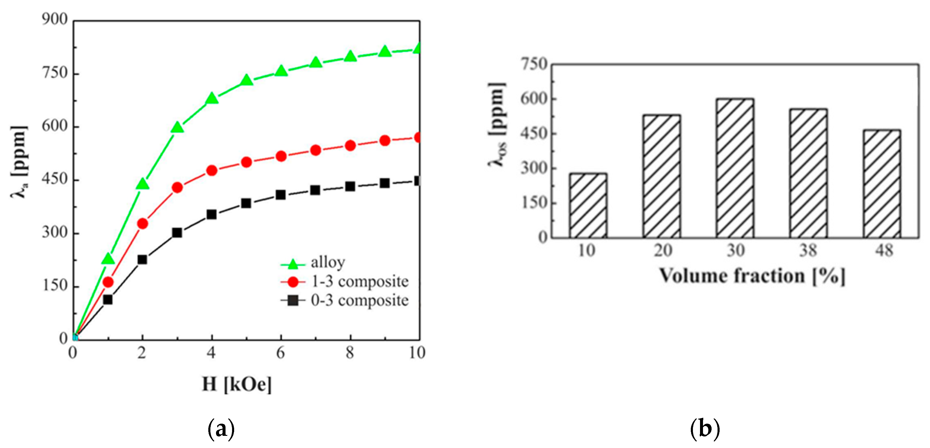
Zhang et al. [34] compared the effects of orientation magnetic field and particle volume fraction on magnetostrictive composites during curing, as shown in Figure 19. First, TD particles and epoxy resin were mixed evenly in a mold, then degassed in vacuum for 30 min, and finally, the mold was placed in air for curing. The composite material obtained was called 0-3 magnetostrictive composite material. When the mold is solidified in a magnetic field, the composite material obtained is called 1-3 magnetostrictive composite material. When the particle volume fraction is the same, the magnetostriction of type 1-3 composites is greater than that of type 0-3 composites, and the saturation magnetostriction of type 1-3 composites reaches 72% of TD alloy. At the same time, the author studied the effect of particle volume fraction on composites. When the volume fraction of particles is 30%, the saturation magnetostriction of the composites is maximum. This is because when the particle volume fraction is low, the magnetostriction of the composite material is small due to the dilution effect of epoxy resin; when the volume fraction of particles is high, the magnetostriction of composites decreases due to the poor contact between particles.
Nersesse Nersessian et al. [35] studied the effects of particle volume fraction and temperature on the properties of composites. At room temperature, the author selected Spurr low viscosity epoxy resin as binder, and tested magnetostrictive composites with particle volume fractions of 13%, 23%, 31%, 37% and 50%, respectively. It is found that when the particle volume fraction is 50%, the saturation magnetostriction of the composites is maximum. At the same time, with the same volume fraction of particles, the author studied the effect of temperature on the saturation magnetostriction of composites. When the temperature is 0 °C or 10 °C, the saturation magnetostriction of magnetostrictive composites reaches the maximum.
At present, the research aims of most literature are 0–3 magnetostrictive composites and 1-3 magnetostrictive composites. Li et al. [36] proposed 2–2 magnetostrictive composites, i.e., the mixture of TD particles and epoxy resin was annealed for 15 min under a magnetic field of 240 kA/m under vacuum. The mixture was then cooled to room temperature under a magnetic field. The obtained sample is 2–2 magnetostrictive composite material. The relationship between magnetostriction and magnetic field strength of composites with and without magnetic field heat treatment was studied. It is found that the magnetostriction of the composites after magnetic field heat treatment is greater than that of the composites without magnetic field heat treatment. At the same time, the authors compare the magnetostriction of composite materials under the pre-compression stress of 0 MPa, 2 MPa, 4 MPa, and 6 MPa, respectively. The results show that the magnetostriction of the composite material is maximum when the pre-compression stress is 6 MPa and minimum when the pre-compression stress is 0 MPa, regardless of whether the composite material is heat-treated by magnetic field.
The strain model of magnetostrictive composites was put forward by Jiuchun Yan et al. [37] The experimental results show that the theoretical model is close to the experimental results. In this paper, the properties of composites with pre-compression stress of 14 MPa and 7 MPa were studied. It is found that the magnetostriction of the composite material is greater when the pre-compression stress is 14 MPa than when the pre-compression stress is 7 MPa. At the same time, the author believes that the saturation magnetostriction of composites increases with the increase of particle volume fraction at low particle volume fraction; However, when the particle volume fraction is greater than 85%, the saturation magnetostriction of the composite decreases with the increase of particle volume fraction.
Rodríguez et al. [38] studied the effects of segment soft-hard ratio, particle size, particle mass fraction, and orientation magnetic field on magnetostrictive composites. When the particle size and mass fraction are the same, the magnetostriction of the composites is the highest when the ratio of segment hardness to segment hardness is 1.5. When the weight fraction of particles is 30%, the magnetostriction of composites with particle sizes ranging from 0–38 μm, 106–212 μm, 212–300 μm and 0–300 μm is compared. It can be found that when the particle size ranges from 212 μm to 300 μm, the magnetostriction of the composites is the highest. Under the same ratio of soft to hard segments, when the weight fraction of particles is 70%, the magnetostriction of the composites is maximum. At the same time, the author compares the properties of the composites when the magnetic field orientation is 0°, 40°, 60°, 80°and 90°, and finds that the magnetostriction of the composites is the largest when the magnetic field orientation is 90°.
Minhong Jiang et al. [39,40,41] studied the effects of particle mass fraction, preloading stress, particle size, orientation magnetic field, and surface treatment on magnetostrictive composites. When the pre-compression stress is 0 MPa and 1 MPa respectively, the magnetostriction of composites with pre-compression stress of 1 MPa is greater than that of composites with pre-compression stress of 0 MPa. The author compared the relationship between magnetostriction and magnetic field strength of composites with alloy particle mass fraction of 84%, 87%, 90%, 93% and 96%. When the mass fraction of particles is 93%, the magnetostriction of the composites is maximum. TD particles are classified into four grades: 0~80 μm, 80~200 μm, 200~450 μm and 450~900 μm, among which the maximum magnetostriction coefficient of composites is obtained when the particle size is 450~900 μm. At the same time, the author found that the properties of the composite material were further improved after applying orientation magnetic field and particle surface treatment.
Xufeng Dong et al. [42] studied the influence of particle size on magnetostrictive composites. Magnetostrictive composites with the same particle volume fraction were prepared by using five narrow distribution particles (30~53 μm, 53~150 μm, 150~300 μm, 300~450 μm, 450~500 μm) and one wide distribution particle (30~500 μm). The adopted binder is unsaturated polyester resin. The experimental results show that among the five narrow distribution particles, the composite with particle size of 53~150 μm has the highest magnetostriction. However, the magnetostriction of composite materials prepared with wide distribution particles (30~500 μm) is greater than that of all composite materials prepared with narrow distribution particles. As far as the average particle size is concerned, it can be seen from the comparison of five kinds of narrow particle composites that the saturation magnetostriction coefficient first increases and then decreases with the increase of the average particle size, and reaches the maximum when the average particle size is 102 μm (particle size distribution is 53~150 μm).
Ting Deng et al. [43] studied the influence of bonding process on the properties of magnetostrictive composites. In this paper, the alloy powders are classified into four different sizes: 0~100 μm, 100~150 μm, 150~300 μm and 300~350 μm. When the applied magnetic field is 13 kOe and the molding pressure is 100 MPa, the saturation magnetostriction of the composite material is maximum when the particle size is 100~150 μm. At the same time, it is found that the magnetostriction of composites increases with the increase of molding pressure. When the molding pressure is 150 MPa, the magnetostriction reaches the maximum value, and then decreases with the increase of molding pressure. This shows that when the molding pressure is 150 MPa, the alloy particles and binder in the composite have been closely bonded, but with the continuous increase of molding pressure, the magnetostriction decreases gradually, because the higher molding pressure will hinder the fluidity of particles in the sample, thus affecting the magnetostriction performance of the sample.
Liping Jiang et al. [44] studied the influence of milling and other processes on the properties of magnetostrictive composites. In this paper, the author adopted the milling process of disc milling and ball milling, and prepared the alloy powder obtained by the two milling processes into composite materials. The results show that the magnetostrictive properties of the composites prepared by ball milling and disk milling have little difference. Therefore, the milling process adopted in this experiment has little effect on magnetostrictive properties.
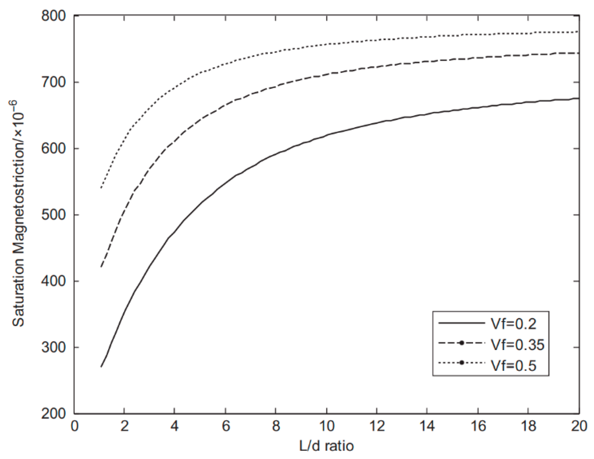
Xinchun Guan et al. [45,46,47] studied the effects of preparation technology, particle volume fraction, particle length–width ratio, and curing temperature on the properties of magnetostrictive composites. In the preparation process of composite materials, the author treated the mixture of magnetostrictive particles and resin by mechanical stirring and high-energy ultrasonic, respectively. It is found that the magnetostriction of composites treated by high-energy ultrasonic method is greater than that of composites treated by mechanical stirring method. This is because the high-energy ultrasonic method can not only disperse the particles evenly, but also remove the oxidation on the surface of the particles. As shown in Figure 20, when the aspect ratio of particles is the same, the saturation magnetostriction of composites with 50% particle volume fraction is greater than that of composites with 20% and 30% particle volume fraction. When the particle content is the same, the saturation magnetostrictive strain of magnetostrictive composites increases with the increase of particle aspect ratio. However, when the aspect ratio of the composite is greater than 10, the saturation magnetostriction of the composite has little change with the aspect ratio of the composite. At the same time, the composite samples were prepared at the curing temperatures of 15 °C, 40 °C, 60 °C and 80 °C, respectively. When the curing temperature was 80 °C, the magnetostriction of the composite was the highest.
Guiheng Zhao et al. [48] studied the effects of particle size and molding pressure on the properties of magnetostrictive composites. The author classified the particle size into 38~58 μm, 58~104 μm, 104~150 μm, 150~250 μm and 250~420 μm. It is found that among the five grades of particle sizes, when the particle size is 250~420 μm, the magnetostriction of the composites is the largest. At the same time, when the forming pressure is 200 MPa, 400 MPa, 600 MPa, 800 MPa, and 1000 MPa respectively, the magnetostrictive strain of the composites with the forming pressure of 400 MPa is the maximum. The author thinks that the molding pressure reduces the voids in the material, increases the density of the composite, and then improves the properties of the composite.
Lin et al. [49] studied the effect of powder crystal orientation on the properties of magnetostrictive composites. It is found that the magnetostriction of 0-3 type or 1-3 type composites presents different trends. When the crystal orientation is < 110 >, the magnetostrictive strain of type 1-3 composites is greater than that of type 0-3 composites. When the crystal orientation is < 100 >, the magnetostrictive strain of type 0-3 composites is greater than that of type 1-3 composites. However, under the same externally applied magnetic field, the magnetostrictive strain of 1-3 type composites with crystal orientation < 110 > is greater than that of 0-3 type composites with crystal orientation <100>.
Hao Meng et al. [50] studied the effects of orientation magnetic field and preloading stress on magnetostrictive composites. The grain size of magnetostrictive powder used is 200–300 μm. Magnetostrictive composites were cured in oriented magnetic fields with magnetic field strengths of 0 Oe, 4000 Oe, 8000 Oe and 12,000 Oe, respectively. Converted to the international system of units, 1 Oe is equal to 1000/4π (≈79.5774715) A/m. It is found that when the magnetic field intensity of the orientation magnetic field is 8000 Oe, the magnetostrictive strain of the composite material is the largest. At the same time, when the magnetic field intensity of the orientation magnetic field is 8000 Oe, the author applies pre-stress of 0 MPa, 5 MPa, 9 MPa, 13 MPa, and 17 MPa to the composite material. Among them, the magnetostrictive strain of the composites is the largest when the pre-compression stress is 17 MPa. Compared with the pre-compression stress of 0 MPa, the magnetostriction of the composite should be about doubled when the pre-compression stress is 17 MPa.
Ran Zhao et al. [51] studied the influence of magnetostrictive materials on the properties of composites. The author compared the relationship between the magnetostriction of TbDyHoFe alloy, TbDyHoFe composite material and TbDyFe composite material and the applied magnetic field. The magnetostriction of TbDyFe composite material reaches saturation at 400 kA/m, and the magnetostriction of TbDyHoFe alloy and TbDyHoFe composite material reaches saturation at 250 kA/m. In addition, the saturation magnetostriction of the TbDyFe composite material is the largest, and the saturation magnetostriction of the TbDyHoFe alloy is the smallest. In the low magnetic field (<100 kA/m), the magnetostriction of the TbDyHoFe composite is the largest, i.e., the sensitivity of the TbDyHoFe composite is higher under the low magnetic field.
Dong et al. [52] studied the influence of the intensity of the orientation magnetic field on the properties of magnetostrictive composites. Magnetic fields of 0 kA/m, 50 kA/m, 80 kA/m and 100 kA/m were applied in the preparation of magnetostrictive composites. It was found that the magnetostrictive strain of the composites gradually increased with the increase of orientation magnetic field strength. When the orientation magnetic field intensity is 100 kA/m, the magnetostrictive strain of the composites is the largest. As shown in Table 3, this paper summarizes the factors affecting the properties of magnetostrictive composites.

4. Prospect of Optical Fiber Current Sensor Based on Magnetostrictive Composite Materials

The improvement of sensor structure and magnetostrictive composite material not only reduces the production cost of the sensor, but also improves the performance of the sensor. The sensor structure is mainly studied from the shape of magnetostrictive material (magnetostrictive composite material), the shape of magnetic permeable material and the number of permanent magnets, etc. Among them, the shape of magnetostrictive material still needs improvement, such as how to make the material smaller and the magnetic flux density more concentrated. The improvement of magnetostrictive composites is mainly studied from the aspects of particle volume fraction, binder type, particle size, orientation magnetic field, and molding pressure. At present, scholars at home and abroad have not reached a consistent conclusion on the effects of particle size, volume content, orientation magnetic field, curing temperature, and molding pressure on the properties of magnetostrictive composites. Therefore, a large number of experiments are needed to unify the effects of particle size, volume content, orientation magnetic field, curing temperature, and molding pressure on the properties of composite materials. The next work is to use finite element simulation to guide the experiment. At the same time, the strain transfer efficiency and demodulation technology of fiber grating deserve further study.

Author Contributions

Conceptualization, S.X. and M.L.; methodology, Q.P.; validation, F.X. and H.X.; investigation, C.L.; data curation, B.L.; writing—original draft preparation, Q.P.; writing—review and editing, S.X.; visualization, J.S.; supervision, M.L.; project administration, S.X.; funding acquisition, F.X. All authors have read and agreed to the published version of the manuscript.

Funding

This research was funded by National Key R&D Program of China (2016YFF0102404; 2016YFF0102401); National Natural Science Foundation of China (NSFC) (51607178); China Postdoctoral Science Foundation (2018T110570; 2019M652005); Xuzhou Science and Technology Innovation Development Project (KC19053); Funding of Chengdu Guojia Electrical Engineering Co., Ltd. (NEEC-2018-B03); Fundamental Research Funds for the Central Universities (2017QNA13); and Priority Academic Program Development of Jiangsu Higher Education Institutions (PAPD) for the financial support to this research.

Institutional Review Board Statement

Not applicable.

Informed Consent Statement

Not applicable.

Data Availability Statement

The data presented in this study are available on request from the corresponding author.

Conflicts of Interest

The authors declare no conflict of interest.

References

  1. Silva, R.M.; Martins, H.; Nascimento, I.; Baptista, J.M.; Ribeiro, A.L.; Santos, J.L.; Jorge, P.; Frazão, O. Optical current sensors for high power systems: A review. Appl. Sci. 2012, 2, 602–628. [Google Scholar] [CrossRef]
  2. Bohnert, K.; Gabus, P.; Kostovic, J.; Brandle, H. Optical fiber sensors for the electric power industry. Opt. Lasers Eng. 2005, 43, 511–526. [Google Scholar] [CrossRef]
  3. Zhang, W.C.; Lai, Y.B.; Zhao, H.; Zhang, L.Y.; Shi, Y.B. Structure optimization and temperature compensation model of GMM-FBG fiber optic current sensor. Electr. Mach. Control 2019, 23, 104–111. [Google Scholar]
  4. Wang, Z.S.; Wang, H.B.; Liu, X.H. Dynamic response of the output force of giant magnetostrictive materials. Int. J. Mech. Mater. Des. 2020, 16, 685–691. [Google Scholar]
  5. Adelsberg, N.; Weber, Y.; Yoff, A.; Shilo, D. Wireless thin layer force sensor based on a magnetostrictive composite material. Smart Mater. Struct. 2017, 26, 065013. [Google Scholar] [CrossRef]
  6. Li, B.S.; Zhong, X.J.; Tong, W.G. FBG current sensor based on magnetostrictive effect. J. Electr. Eng. Technol. 2009, 24, 95–100. [Google Scholar]
  7. Joule, J.P. On a new class of magnetic forces. Ann. Electr. Magn. Chem. 1842, 8, 219–224. [Google Scholar]
  8. Huang, J.H.; Nan, C.W.; Li, R.M. Micromechanics approach for effective magnetostriction of composite materials. J. Appl. Phys. 2002, 91, 9261–9266. [Google Scholar] [CrossRef]
  9. Olabi, A.G.; Grunwald, A. Design and application of magnetostrictive materials. Mater. Des. 2008, 29, 469–483. [Google Scholar] [CrossRef] [Green Version]
  10. Du, T.; Zhang, H.P. Application research of rare earth-iron series giant magnetostrictive materials. Met. Funct. Mater. 1997, 4, 173–176. [Google Scholar]
  11. Basumallick, N.; Chatterjee, I.; Biswas, P.; Dasgupta, K.; Bandyopadhyay, S. Fiber bragg grating accelerometer with enhanced sensitivity. Sens. Actuators A Phys. 2011, 173, 108–115. [Google Scholar] [CrossRef]
  12. Liu, H.L.; Or, S.W.; Tam, H.Y. Magnetostrictive composite-fiber bragg grating (MC-FBG) magnetic field sensor. Sens. Actuators A Phys. 2012, 173, 122–126. [Google Scholar] [CrossRef]
  13. Satpathi, D.; Moore, J.A.; Ennis, M.G. Design of a Terfenol-D based fiber-optic current transducer. IEEE Sens. J. 2005, 5, 1057–1065. [Google Scholar] [CrossRef]
  14. Cremonezi, A.O.; Ferreira, E.C.; Biazon, A.J.; Dias, J.A.S. A fiber bragg grating rms current transducer based on the magnetostriction effect using a Terfenol-D toroidal-modulator. IEEE Sens. J. 2013, 13, 683–690. [Google Scholar] [CrossRef]
  15. De Nazare, F.V.B.; Werneck, M.M. Compact optomagnetic bragg-grating-based current sensor for transmission lines. IEEE Sens. J. 2015, 15, 100–109. [Google Scholar] [CrossRef]
  16. Dante, A.; Lopez, J.D.; Trovão, T.; Mok, R.W.; Carvalho, C.C.; Allil, R.C.D.S.B.; Werneck, M.M. A compact FBG-Based toroidal magnetostrictive current sensor with reduced mass of Terfenol-D. In OSA Optical Sensors and Sensing Congress 2019; Optical Society of America: Washington, DC, USA, 2019. [Google Scholar]
  17. Dante, A.; Lopez, J.D.; Carvalho, C.C.; Allil, R.C.D.B.; Werneck, M.M. A compact FBG-Based magnetostrictive optical current sensor with reduced mass of Terfenol-D. IEEE Photonics Technol. Lett. 2019, 31, 1461–1464. [Google Scholar] [CrossRef]
  18. Lopez, J.D.; Dante, A.; Bacurau, R.M.; Cremonezi, A.O.; Mok, R.W.; Carvalho, C.C.; Allil, R.C.S.B.; Ferreira, E.C.; Werneck, M.M. Fiber-Optic current sensor based on FBG and optimized magnetostrictive composite. IEEE Photonics Technol. Lett. 2019, 31, 1987–1990. [Google Scholar] [CrossRef]
  19. Lopez, J.D.; Dante, A.; Cremonezi, A.O.; Bacurau, R.M.; Carvalho, C.C.; da Silva Barros Allil, R.C.; Ferreira, E.C.; Werneck, M.M. Fiber-Optic current sensor based on FBG and Terfenol-D with magnetic flux concentration for enhanced sensitivity and linearity. IEEE Photonics Technol. Lett. 2020, 20, 3572–3578. [Google Scholar] [CrossRef]
  20. Wang, S.; Wan, F.; Zhao, H.; Chen, W.; Zhang, W.; Zhou, Q. A sensitivity-enhanced fiber grating current sensor based on giant magnetostrictive material for large-current measurement. Sensors 2019, 19, 1755. [Google Scholar] [CrossRef] [Green Version]
  21. Jiang, M.H.; Gu, Z.F.; Liu, X.Y. Study on preparation and properties of Al/Tb0.30Dy0.70Fe1.95 composites. Powder Metall. Ind. 2009, 27, 119–122, 126. [Google Scholar]
  22. Jiang, M.H.; Gu, Z.F.; Liu, X.Y.; Cheng, J.; Zhou, X.J. Preparation of Al/Tb0.30Dy0.70Fe1.95 magnetostrictive composites by powder sintering. J. Aeronaut. Mater. 2009, 29, 13–16. [Google Scholar]
  23. Lim, S.H.; Kim, S.R.; Kang, S.Y.; Park, J.K.; Nam, J.T.; Son, D. Magnetostrictive properties of polymer-bonded Terfenol-D composites. J. Magn. Magn. Mater. 1999, 191, 113–121. [Google Scholar] [CrossRef]
  24. Kaleta, J.; Lewandowski, D.; Mech, R. Magnetostriction of field-structural composite with Terfenol-D particles. Arch. Civ. Mech. Eng. 2015, 15, 897–902. [Google Scholar] [CrossRef]
  25. Quintero, S.; Braga, A.; Weber, H.; Bruno, A.C.; Araujo, J.F.D.F. A magnetostrictive composite-fiber bragg grating sensor. Sensors 2010, 10, 8119–8128. [Google Scholar] [CrossRef] [Green Version]
  26. Zhao, X.; Zhao, L.; Wang, R.; Yan, J.; Tian, X.; Yao, Z.; Tegus, O. The microstructure, preferred orientation and magnetostriction of Y doped Fe-Ga magnetostrictive composite materials. J. Magn. Magn. Mater. 2019, 491, 165568.1–165568.8. [Google Scholar] [CrossRef]
  27. Dong, X.; Qi, M.; Guan, X.; Li, J.; Ou, J. Magnetostrictive properties of titanate coupling agent treated Terfenol-D composites. J. Magn. Magn. Mater. 2012, 324, 1205–1208. [Google Scholar] [CrossRef]
  28. Dong, X.; Ou, J.; Guan, X.; Qi, M. Optimal orientation field to manufacture magnetostrictive composites with high magnetostrictive performance. J. Magn. Magn. Mater. 2010, 322, 3648–3652. [Google Scholar] [CrossRef]
  29. Li, B.; Zhang, T.; Wu, Y.; Jiang, C. High-performance magnetostrictive composites with large particles volume fraction. J. Alloy. Compd. 2019, 805, 1266–1270. [Google Scholar] [CrossRef]
  30. Tomiczek, A.E.; Mech, R.; Dobrzanski, L.A.; Tanski, T. Magnetomechanical properties of composite materials with giant magnetostriction. Arch. Metall. Mater. 2015, 60, 1819–1824. [Google Scholar] [CrossRef]
  31. Tomiczek, A.E.; Mech, R.; Dobrzanski, L.A. Variation of magneto-mechanical properties in giant magnetostrictive composite materials. Polym. Compos. 2017, 38, 797–802. [Google Scholar] [CrossRef]
  32. Tian, J.J.; Zuo, Z.J.; Pan, D.A.; Zhang, S.G. Bonded Terfenol-D composites with low eddy current loss and high magnetostriction. Rare Met. 2010, 29, 579–582. [Google Scholar] [CrossRef]
  33. Jia, A.; Zhang, T.L.; Meng, H.; Jiang, C.B. Magnetostriction and eddy current loss of bonded giant magnetostrictive particle. Acta Metall. Sin. 2009, 45, 1473–1478. [Google Scholar]
  34. Zhang, Z.R.; Liu, J.J.; Song, X.H.; Li, F.; Zhu, X.Y.; Si, P.Z. Magnetoelastic properties of epoxy resin based TbxHo0.9-xNd0.1(Fe0.8Co0.2)1.93 particulate composites. Mater. Sci. Pol. 2017, 35, 81–86. [Google Scholar] [CrossRef] [Green Version]
  35. Nersessian, N.; Or, S.W.; Carman, G.P. Magneto-thermo-mechanical characterization of 1–3 type polymer-bonded Terfenol-D composites. J. Magn. Magn. Mater. 2003, 263, 101–112. [Google Scholar] [CrossRef]
  36. Li, S.Y.; Wang, B.W.; Weng, L.; Zhou, Y.; Sun, Y.; Huang, W.M. The effect of magnetic field heat treatment on magnetostriction of Terfenol-D 2–2 composites. J. Magn. Magn. Mater. 2008, 320, 806–809. [Google Scholar] [CrossRef]
  37. Yan, J.C.; Lu, S.X.; Yang, S.Q.; He, S.Y. Simulation on magnetostriction strain of polymer-bonded Terfenol-D composites. J. Mater. Sci. Technol. 2003, 19, 103–104. [Google Scholar]
  38. Rodriguez, C.; Rodriguez, M.; Orue, I.; Vilas, J.L.; Barandiaran, J.M.; Gubieda, M.L.F.; Leon, L.M. New Elastomer-Terfenol-D magnetostrictive composites. Sens. Actuators A Phys. 2009, 149, 251–254. [Google Scholar] [CrossRef]
  39. Jiang, M.H.; Gu, Z.F.; Liao, H.Y.; Liu, X.Y. Preparation and characterization of high performance bonded giant magnetostrictive composites. J. Sichuan Univ. 2008, 5, 116–120. [Google Scholar]
  40. Jiang, M.H.; Gu, Z.F.; Liu, X.Y.; Cheng, G.; Zhou, H.Y. Study on magnetic properties of high performance rare earth-iron giant magnetostrictive composites. J. Sichuan Univ. 2009, 41, 126–131. [Google Scholar]
  41. Jiang, M.H.; Zhu, Y.C.; Yang, P.S. Preparation technology, microstructure and magnetostrictive properties of rare earth giant magnetostrictive composites. Rear Earth 2004, 6, 26–30. [Google Scholar]
  42. Dong, X.F.; Guan, X.C.; Ou, J.P.; Qi, M. Effect of particle size distribution on properties of resin-based magnetostrictive composites. Acta Mater. Compos. Sin. 2010, 27, 1–8. [Google Scholar]
  43. Deng, T.; Gu, Z.F.; Cheng, G. Effect of bonding process on magnetostrictive properties of high praseodymium alloy composites. Electr. Eng. Mater. 2011, 2, 30–32. [Google Scholar]
  44. Jiang, L.P.; Zhao, Z.Q.; Wu, S.X.; Huang, J.M.; Wen, Y.C.; Zuo, L. Study on the preparation technology of bonded rare earth magnetostrictive materials. Rear Earth 2005, 4, 30–32. [Google Scholar]
  45. Guan, X.C.; Dong, X.F.; Ou, J.P. Preparation and properties of resin-based magnetostrictive composites under ultrasound. Funct. Mater. 2008, 8, 1264–1267. [Google Scholar]
  46. Guan, X.C.; Dong, X.F.; Ou, J.P. Predicting performance of polymer-bonded Terfenol-D composites under different magnetic fields. J. Magn. Magn. Mater. 2009, 321, 2742–2748. [Google Scholar] [CrossRef]
  47. Guan, X.C.; Dong, X.F.; Ou, J.P. Effect of thermal residual stress on dynamic and static magnetostrictive properties of resin-based magnetostrictive composites. Acta Mater. Compos. Sin. 2008, 1, 11–16. [Google Scholar]
  48. Zhao, G.H.; Liu, Y.Q.; Zhang, H.P. Study on phenolic bonded TbDyFe rare earth magnetostrictive material. Powder Metall. Ind. 2019, 29, 55–60. [Google Scholar]
  49. Lin, L.L.; Liu, J.J.; Shen, W.C.; Ding, Q.L.; Wang, M.K.; Du, J.; Si, P.Z. Magnetomechanical behavior of Tb0.2Dy0.8-xPrx(Fe0.8Co0.2)1.93/epoxy pseudo-1–3 particulate composites. Appl. Phys. A Mater. Sci. Process. 2018, 124, 706–713. [Google Scholar] [CrossRef]
  50. Meng, H.; Zhang, T.L.; Jiang, C.B.; Xu, H.B. Grain-<111>-oriented anisotropy in the bonded giant magnetostrictive material. Appl. Phys. Lett. 2010, 96, 102501. [Google Scholar] [CrossRef]
  51. Zhao, R.; Wang, B.W.; Cao, S.Y.; Huang, W.M.; Lu, Q.G.; Yan, J.W. Magnetostrictive and magnetic properties of Tb0.29Dy0.48Ho0.23Fe1.9 fiber/epoxy composites. J. Magn. 2018, 23, 280–284. [Google Scholar] [CrossRef]
  52. Dong, X.; Qi, M.; Guan, X.; Ou, j. Microstructure analysis of magnetostrictive composites. Polym. Test. 2010, 29, 369–374. [Google Scholar] [CrossRef]
Figure 1. Magnetostriction phenomenon.
Applsci 11 00161 g001
Figure 2. Schematic diagram of magnetostriction.
Applsci 11 00161 g002
Figure 3. Schematic diagram of fiber grating.
Applsci 11 00161 g003
Figure 4. Influence of frequency doubling on magnetostrictive materials. (a) “frequency doubling” phenomenon. (b) no “frequency doubling” phenomenon.
Applsci 11 00161 g004
Figure 5. Role of permanent magnets.
Applsci 11 00161 g005
Figure 6. Sensor system diagram.
Applsci 11 00161 g006
Figure 7. Optical fiber current sensor based on 40 g cylindrical rod magnetostrictive material.
Applsci 11 00161 g007
Figure 8. Optical fiber current sensor based on 144 g annular solid magnetostrictive material.
Applsci 11 00161 g008
Figure 9. Optical fiber current sensor based on 70 g rectangular magnetostrictive material.
Applsci 11 00161 g009
Figure 10. Ring optical fiber current sensor based on 5.6 g magnetostrictive material.
Applsci 11 00161 g010
Figure 11. Ring optical fiber current sensor based on 2.0 g magnetostrictive material.
Applsci 11 00161 g011
Figure 12. Optical fiber current sensor based on 1.5 g hyperboloid magnetostrictive composite material.
Applsci 11 00161 g012
Figure 13. Optical fiber current sensor based on 0.42 g cuboid magnetostrictive composite material.
Applsci 11 00161 g013
Figure 14. Optical fiber current sensor based on magnetostrictive material with enhanced sensitivity.
Applsci 11 00161 g014
Figure 15. Preparation process of magnetostrictive composites.
Applsci 11 00161 g015
Figure 16. Optical fiber current sensor based on magnetostrictive composite material.
Applsci 11 00161 g016
Figure 17. Comparison of the relationship between magnetostriction and magnetic field strength of composites with different particle volume fractions when the particles are treated with coupling agent or not.
Applsci 11 00161 g017
Figure 18. The relationship between magnetostriction and magnetic field strength of composites with different particle volume fractions. (a) The pre-compression stress is 0 MPa. (b) The pre-compression is 10 MPa.
Applsci 11 00161 g018
Figure 19. (a) Effect of orientation magnetic field on magnetostrictive composites during curing. (b) Effect of particle volume fraction on magnetostrictive composites during curing.
Applsci 11 00161 g019
Figure 20. Relationship between saturation magnetostriction and particle aspect ratio of composites with different particle volume fractions.
Applsci 11 00161 g020
Table 1. Comparison: FBG-based current sensorsfor high-voltage lines.
ReferenceGeometryTD MassLinear Range
[13]Cylindrical40250–700 A
[14]Toroidal144320–900 A
[15]Cubic74/
[16]Toroidal5.6105–650 A
[17]Toroidal2.050–400 A
[18]Hyperbolic1.515–450 A
[19]Cuboid0.42100–800 A
Table 2. Research summary of sensor structure.
Serial NumberAuthorArchitectural FeatureAdvantages and Disadvantages
1Debashis Satpathi [13]1. 40 g cylindrical rod magnetostrictive material
2. preloading stress mechanical device
3. DC bias coil
The linearity of the sensor is high, but the structure is complex and the sensor is active.
2Cremonezi [14]1. 144 g annular solid magnetostrictive material
2. stainless-steel compression ring
The measurement of alternating current is realized with small measurement error, but the frequency-doubling phenomenon
will occur in the measurement process.
3Nazaré and Werneck [15]1. 74 g solid cuboid magnetostrictive material
2. permanent magnet
The sensor is passive and eliminates the phenomenon of frequency-doubling, but magnetostrictive materials are expensive and fragile.
4Alex Dante [16]1. 5.6 g annular magnetostrive
material
2. annular magnetic conductive material
The cost of the sensor is greatly reduced, and the sensitivity is high, but the magnetostrictive material is difficult to form.
5Alex Dante [17]1. 2.0 g annular magnetostrive materialFurther reduce the cost and improve the sensitivity, which is suitable for
fault detection.
6Juan D. Lopez [18]1. 1.5 g hyperboloid magnetostrictive material
2. open-loop structure
Lower cost, higher sensitivity, faster response time, and easy installation.
7Juan D. Lopez [19]1. 0.42 g rectangular magnetostriction material
2. circular magnetic permeability material from coarse to fine
The cost is the lowest, the magnetic flux density is concentrated and the maximum non-linear error of the sensor is reduced, but the temperature error is not compensated.
8S. Wang [20]1. The T-shaped structure is placed in the copper support structure
2. the copper screw exerts pressure
Sensitivity is enhanced,
but the structure is complex.
Table 3. Research Summary of Magnetostrictive Composites.
Serial NumberInfluencing Factors of Properties of Composite MaterialsViews of Different Authors
1Preloading stress1. JKaleta et al. think that the optimum preloading stress is 9 MPa
2. Quintero et al. think that the optimum preloading stress is 8.6 MPa
3. Bochen Li et al. think that the best preloading stress is 10 MPa
4. Tomiczek et al. think that the best preloading stress is 2 MPa
5. Li et al. think that the best preloading stress is 6 MPa
6. Jiuchun Yan et al. the optimum preloading stress is 14 MPa
7. Hao Meng et al. think that the best preloading stress is 17 MPa
2Orientation magnetic field directionGMPC with vertical orientation magnetic field direction is better than GMPC with parallel orientation magnetic field direction
3Orientation magnetic field strength1. Xufeng Dong et al. believe that the optimal orientation magnetic field strength of GMPC with particle volume fractions of 20%, 30%, and 50% are 30 kA/m, 80 kA/m and 100 kA/m, respectively.
2. Hao Meng et al. think that the best orientation magnetic field is 8000 Oe.
3. Dong et al. think that the best orientation magnetic field is 100 kA/m
4Particle surface treatmentGMPC treated with coupling agent is better than GMPC untreated with coupling agent
5Types of adhesivesEpoxy resin is superior to polyurethane resin
6Segment soft-hard ratioC. Rodríguez et al. think that the best segment soft-hard ratio is 1.5
7TemperatureNersesse Nersessian et al. think that the best temperature is 0 °C or 10 °C
8Particle volume fraction1. Quintero thinks that the best particle volume fraction is 30%
2. Bochen Li et al. think that the best particle volume fraction is 57%
3. Nersesse Nersessian et al. think that the best particle volume fraction is 50%
4. Jiuchun Yan et al. think that the best particle volume fraction is 85%
9Particle mass fraction1. Jia Ao et al. think that the best particle mass fraction is 90%
2. Rodríguez et al. think that the best particle mass fraction is 70%
3. Minhong Jiang and others believe that the best particle mass fraction is 93%
10Forming pressure1. Jianjun Tian et al. and Jia Ao et al. think that the best molding pressure is 200 MPa
2. Ting Deng and others think that the best molding pressure is 150 MPa
3. Guiheng Zhao and others believe that the best molding pressure is 400 MPa
11Doping rare-earth elementsGMPC doped with rare-earth elements is better than GMPC undoped with rare-earth elements
12Magnetic heat treatmentGMPC after magnetic field heat treatment is better than GMPC without magnetic field heat treatment
13Particle size of magnetostrictive material1. Quintero et al. and Z.R. ZHANG et al. think that the best particle size range is > 200 μm
2. Tomiczek et al. think that the best particle size range is 106–212 μm
3. Jianjun Tian et al. think that the best particle size range is 50–80 μm
4. Rodríguez et al. think that the best particle size range is 212–300μm
5. Minhong Jiang and others think that the best particle size range is 450~900 μm
6. Xufeng Dongand others think that the best particle size range is 30~500 μm
7. Ting Deng et al. think that the best particle size range is 100~150 μm
8. Guiheng Zhao and others believe that the best particle size range is 250~420 μm
14Preparation technologyThe composites treated by high-energy ultrasonic method are better than those treated by mechanical stirring method
15Curing temperatureXinchun Guan and others believe that the best curing temperature is 80 °C
16Particle aspect ratioXinchun Guan and others believe that the best aspect ratio of particles is 10
17Powder crystal orientationThe properties of composites with different crystal orientations are different
18Types of magnetostrictive materialsThe properties of composites with different kinds of magnetic field stretching materials are different
Publisher’s Note: MDPI stays neutral with regard to jurisdictional claims in published maps and institutional affiliations.