Article

Critical Temperature and Frequency Characteristics of GPLs-Reinforced Composite Doubly Curved Panel

1
Department of Mechanical Engineering, Central Tehran Branch, Islamic Azad University, Tehran 477893855, Iran
2
Department of Mechanical Engineering, Faculty of Industrial and Mechanical Engineering, Qazvin Branch, Islamic Azad University, Qazvin 3414896818, Iran
3
Center of Excellence in Design, Robotics, and Automation, Department of Mechanical Engineering, Sharif University of Technology, Azadi Avenue, Tehran 11365-9567, Iran
4
School of Mechanical Engineering, Hangzhou Dianzi University, Hangzhou 310018, China
5
School of Materials Science and Engineering, State Key Laboratory of Silicon Materials, Zhejiang University, Hangzhou 310027, China
*
Author to whom correspondence should be addressed.
Appl. Sci. 2020, 10(9), 3251; https://doi.org/10.3390/app10093251
Submission received: 12 March 2020 / Revised: 26 April 2020 / Accepted: 28 April 2020 / Published: 7 May 2020
(This article belongs to the Section Mechanical Engineering)

Abstract

:
In this study, critical temperature and frequency characteristics of a doubly curved panel are reinforced by graphene nanoplatelets (GPLs) with the aid of a two-dimensional generalized differential quadrature method (2D-GDQM) are investigated. The size effects are included using nonlocal strain gradient theory (NSGT) that has two length scale parameters, and the panel is modeled as a panel using high order shear deformation theory (HSDT). The mechanical properties of GPLs are calculated based on the rule of mixtures and the modified Halpin–Tsai model. The novelty of the current study is in considering the effects of the thermal environment, various boundary conditions, and size effects on the frequency and critical temperature of the GPLRC panel. The validation is performed through the comparison of the numerical results for the frequency of the GPLRC panel and the literature. For more verification, a finite element model is presented using the finite element package to simulate the response of the current structure. The results created from a finite element simulation illustrate a close agreement with the numerical method results. The results demonstrate that GPLs’ weight function, the ratio of panel curvature (R1/R2), GPLs’ pattern, and size-dependent parameters have noticeable effects on the frequency and critical temperature characteristics of the GPLs-reinforced composite (GPLRC) curved panel. The favorable suggestion of this survey is that when designing the GPLRC structure, special attention should be paid to size-dependent parameters because the nonlocal and length scale parameters have an essential role in the static and dynamic behaviors of the GPLRC panel.

1. Introduction

Due to the recent advancements in science and technology [1,2,3,4,5,6,7,8,9], graphene nanoplatelet (GPL) reinforcement has attracted considerable attention. Some applications of GPL reinforcement are reported in Ref. [10]. Also, the mechanical properties of GPL reinforcements make them an appropriate choice to be used in chemistry, physics, electrical engineering, materials science, and nanoengineering applications [10].
Suna et al. [11] compared the fracture characteristics of the functionally graded (FG) cemented carbide reinforced by the GPL with pure ones. They showed that the property of GPLs stops nanocracks in the nanocomposites. Furthermore, an experimental study by Rafiee et al. [12] showed that the mechanical properties of epoxy nanocomposites are reinforced by different reinforcements such as GPL, multiwalled carbon nanotube (MWCNT), and single-walled carbon nanotube (SWCNT). Their work showed that the reinforcement GPL makes structures stronger and stiffer than other reinforcing. Furthermore, many studies express that adding a small amount of GPL causes a considerable change to the thermo-electro-mechanical aspects of the properties of the systems.
In the past several years, it was remarkable that the micro and nano parts strengthened by GPLs are much more practical in industrial fields, and for this reason, the dynamic features of the nanostructures reinforced with GPL is a vital field of analysis. Based on nonlocal strain gradient theory (NSGT) and by considering the thermal effects, Safarpour et al. [13] investigated the small-scale influences on a size-dependent laminated composite cylindrical nanoshell. They showed that the ply angle is more vital in the phase of the velocity of nanostructures and the higher wavenumbers. The wave propagation in the laminated cylindrical microshell was scrutinized basis on NSGT and strain gradient theory by Zeighampour et al. [14] Their results indicate that the phase velocity has an increment by decreasing the nonlocal constant parameter. Based on NSGT in the context of a high-order shear deformation beam theory, Sahmani et al. are studied the frequency behavior of a postbuckled GPLs-reinforced composite (GPLRC) micro/nano beam [15]. Their results demonstrate that in the prebuckled region, the fundamental frequency of the system decreases by increasing the value of the nonlocal parameter. Furthermore, numerous researches [13,16,17,18,19,20,21,22,23,24,25,26,27,28,29,30,31,32,33,34,35,36,37,38,39] scrutinized the stability and instability regions of the complex micro- and nano-structures by utilizing numerical and analytical procedures. In the field of critical temperature study of micro- and nano-structures, by considering the thermal effects of the environment and the axial force, the size-dependent postbuckling and buckling characteristics of cylindrical nano panels are analyzed by Sahamni et al. [40]. They found that the value of the minimum load of the post-buckling domain cannot be affected by the thermal influences of the environment. Sahmani and Aghdam [41] investigated the nonlocal electro-thermomechanical instability of an FGM nano panel based on a new shear deformation theory, which contains exponential shear stress distribution. The nano panel has been covered by piezoelectric sheets, and the temperature effects have been considered. They displayed that by considering the nonlocality size effects, the related minimum load of the postbuckling domain increases, while the critical buckling load decreases. Sahmani et al. [42] scrutinized the nonlinear instability analysis of an electrical nanoshell based upon NSGT. It can be demonstrated from their results that the strain gradient size dependency leads to increases the buckling stiffness, while the nonlocal size effect cause to decreases it. Sarvestani et al. investigated the size-dependent FG doubly curved panel [43]. They applied first-order shear deformation theory and the modified couple stress. Their results investigate various parameters such as aspect ratio, the influences of material length scale, and panel curvature.
Shasha et al. [44] introduced an exact novel model based on surface elasticity and Kirchhoff theory to determine the vibration performance of a double-layered microstructure. The surface effect is captured in their model as the main novelty. The results obtained with the aid of their modified model showed that the vibration performance of the double-layered microstructure is quite higher than the single-layered one. Gholami et al. [45] employed a more applicable gradient elasticity theory with the capability of including higher-order parameters and the size effect in the analysis of the instability of the FG cylindrical microshell. Their results confirmed that the radius to thickness ratio and size effect have a significant influence on the stability of the microsystem. Based on the first-order shear deformation theory (FSDT), Mohammadimehr et al. [46] conducted a numerical study in the dynamic and static stability performance of a composite circular plate by implementing two-dimensional generalized differential quadrature method (GDQM). Moreover, they considered the thermomagnet field to define the sandwich structure model. As another work, Mohammadimehr et al. [47] applied DQM in the framework of modified couple stress theory (MCST) to describe stress filed and scrutinize the dynamic stability of an FG boron nitride nanotubes reinforced circular plate. They claimed that using reinforcement in a higher volume fraction promotes the strength and vibration response of the structure. Sajadi et al. studied the nonlinear oscillation and stability of microcircular plates subjected to electrical field actuation and mechanical force [48]. They concluded that pure mechanical load plays a more dominant role in the stability characteristics of the structure in comparison to the electromechanical load. In addition, they confirmed the positive impact of AC or DC voltage on the stability of the system in different cases of application. To determine the critical angular speed of the spinning circular shell coupled with the sensor at its end, Safarpour et al. [21] applied GDQM to analyze forced and free oscillatory responses of the structure on the base of thick shell theory. Through a theoretical approach, Wang et al. [49] obtained critical temperature and thermal load of a nano circular shell. Safarpour et al. [50] introduced a numerical technique with high accuracy to study the static stability, forced, and free vibration performance of a nanosized FG circular shell in exposure to thermal loading. Wang et al. [51] reported the nonlinear dynamic performance of size-dependent circular plates with the piezoelectric actuator in the exposure of a thermal loading with the aid of MCS incorporated with surface elasticity theory to consider the size effects. They highlighted the considerable effect of geometrical nonlinearity on the dynamic characteristics of the system. By employing FSDT, NSGT, DQM, and Hamilton’s principle, Mahinzare et al. [52] presented a comprehensive parametric investigation in the size-dependent vibration performance of FG circular plate by considering the electro-elastic, thermal and rotational effects. They showed the considerable impact of spinning velocity on the natural frequencies of nanosized systems. In another investigation, the same authors [53] studied the size-dependent vibration response of a spinning two-directional FG circular plate integrated with the piezoelectric actuator (PIAC) based on DQM, Hamilton’s principle, and FSDT. The results confirmed the high dependency of the dynamic performance of the circular plate to spinning load and externally applied voltage. In the field of structural stability analysis, Safarpour et al. [54,55,56,57,58,59,60,61,62,63,64,65,66,67,68] presented buckling and vibrational analysis of the structures with various geometrical parameters.
As the first research, critical temperature and frequency characteristics of a GPLRC panel in the thermal environment are explored. The mechanical properties of GPLs are calculated based on the rule of mixtures and the modified Halpin–Tsai model. Hamilton’s principle is employed to develop governing equations and boundary conditions. To solve dynamic equations, FSDT and 2D-GDQM are performed. Finally, the effects of various parameters such as geometric and NSGT parameters, and R1/a, on the static and dynamic features of the current system are studied in detail.

2. Theory and Formulation

A GPLRC cylindrical panel in the thermal environment is shown in Figure 1. As drawn in Figure 1, for modeling the GPLRC materials as reinforcing of the system, four different distributions are considered. Functions of the volume fraction for each diagram along thickness direction are stated as [69]:
V G P L ( k ) = V G P L G P L U D ,     P a t t e r n   1 V G P L ( k ) = 2 V G P L | 2 k N L 1 | N L G P L X ,     P a t t e r n   2 V G P L ( k ) = 2 V G P L [ 1 ( | 2 k N L 1 | ) ] N L G P L O ,     P a t t e r n   3 V G P L ( k ) = 2 V G P L ( 2 k 1 ) N L G P L A ,     P a t t e r n   4
The parameters that are used in Equation (1) are given in Ref [69] in detail. The relation between weight fraction g G P L and its V G P L are acquired as follows:
V G P L = g G P L g G P L + ( ρ G P L / ρ m ) ( 1 g G P L )
where ρ m and ρ G P L are the mass densities of the polymer matrix and the GPL, respectively. Also, the effective elasticity modulus according to Halpin–Tsai model can be computed as [70]:
E ¯ = ( 3 8 ( 1 + ξ L η L V G P L   1 η L V G P L ) + 5 8 ( 1 + ξ W η W V G P L   1 η W V G P L )   ) ×   E M
Here ξ L = 2 L G P L t G P L   ξ W = 2 w G P L t G P L , η L = ( E G P L E M ) 1 ( E G P L E M ) + ξ L and η W = ( E G P L E M ) 1 ( E G P L E M ) + ξ W . By utilizing the rule of mixture, other material properties are stated as:
ν ¯ = ν G P L V G P L + ν M V M , ρ ¯ = ρ G P L V G P L + ρ M V M , α ¯ = α G P L V G P L + α M V M
In the above equations, EM, ν M , α M are the elasticity modulus, Poisson’s ratio, and thermal expansion of the matrix, respectively. Also, ν G P L , and α G P L are Poisson’s ratio, and thermal expansion of the GPL, respectively.
Displacement Fields
Based on HSDT, the displacement field can be stated as [71]:
u ( x , y , z , t ) = u 0 ( x , y , t ) + z ϕ x ( x , y , t ) c 1 z 3 × [ w 0 ( x , y , t ) x + ϕ x ( x , y , t ) ] v ( x , y , z , t ) = v 0 ( x , y , t ) + z ϕ y ( x , y , t ) c 1 z 3 × [ w 0 ( x , y , t ) y + ϕ y ( x , y , t ) ] w ( x , y , z , t ) = w 0 ( x , y , t )
In the Equation (5), u, v, and w show displacement components at any point in the structure. Furthermore, u0, v0, and w0 represent the displacement components at a point on the midplane of the plate around axial, circumferential, and thickness directions of the system, respectively. ϕ x and ϕ y are the rotation of the normal to the element middle plane in the circumferential and axial directions, respectively. In addition, c 1 is expressed as 4/3h2 in HSDT. The strain components can be given by:
{ ε x x ε y y γ x y γ x z γ y z } = [ u x + w 0 R 1 v y + w 0 R 2 u y + v x u z + w x v z + w y ]
Finally, by replacing Equation (5) in Equation (6a), we have:
{ ε x x ε y y γ x y γ x z γ y z } = [ u 0 x + z ϕ x x z 3 c 1 ( ϕ x x + 2 w 0 x 2 ) + w 0 R 1 v 0 y + z ϕ x y z 3 c 1 ( ϕ y y + 2 w 0 y 2 ) + w 0 R 2 u 0 y + v 0 x + z ( ϕ x y + ϕ y x ) z 3 c 1 ( ϕ x y + ϕ y x + 2 2 w 0 x y ) ( 1 3 z 2 c 1 ) ( ϕ x + w 0 x ) ( 1 3 z 2 c 1 ) ( ϕ y + w 0 y ) ]
It should be noted that our displacement field satisfies stress-free boundary conditions ( σ x z | x , y , ± h / 2 = σ y z | x , y , ± h / 2 ) and surface effects are not taken into account.
Strain–Stress Relations
The constitutive relations between stress and strain can be declared as following [24,29,72,73,74,75,76,77,78,79,80,81,82]:
{ σ x x σ y y σ x y σ x z σ y z } = [ Q 11 Q 12 0 0 0 Q 21 Q 22 0 0 0 0 0 Q 44 0 0 0 0 0 Q 55 0 0 0 0 0 Q 66 ] { ε x x α Δ T ε y y α Δ T γ x y γ x z γ y z }
In Equation (7) α and Δ T are thermal expansions and temperature alteration, respectively. Additionally, Δ T = T T 0 , where T 0 is the ambient temperature, and it is considered as T0 = 300 K. Furthermore, in Ref. [62], the stiffness coefficients are presented in detail.
Hamilton’s Principle
For obtaining governing equations and their related boundary conditions using Hamilton’s principle, the following equation must be used [37,38,39,75,76,83]:
t 1 t 2 ( δ K δ U δ W ) d t = 0
The parameters of K and U are the kinetic and strain energy, respectively [84,85,86,87,88,89,90,91].
K = V 0.5 × ρ [ ( u t ) 2 + ( v t ) 2 + ( w t ) 2 ] d V
The first variation of Equation (9) is presented in the Appendix A.
δ U = 1 2 V σ i j δ ε i j d V = = A [ N x x ( δ u 0 x δ w 0 R 1 ) + M x x δ ϕ x x P x x c 1 ( δ ϕ x x + 2 δ w 0 x 2 ) + N y y ( δ v 0 y δ w 0 R 2 ) + M y y δ ϕ x y P y y c 1 ( δ ϕ y y + 2 δ w 0 y 2 ) + N x y δ u 0 y + N x y δ v 0 x + M x y ( δ ϕ x y + δ ϕ y x ) P x y c 1 ( δ ϕ x y + δ ϕ y x + 2 2 δ w 0 x y ) + ( Q x z 3 S x z c 1 ) ( δ ϕ x + δ w 0 x ) + ( Q y z 3 S y z c 1 ) ( δ ϕ y + δ w 0 y ) ]   d A
The parameters that are introduced in Equation (10) are presented in the Appendix A.
Nonlinear Temperature Changes
For a typical GPLRC panel, which is in the temperature environment, it is assumed that the temperature can be distributed across its thickness. The parameter of W is the work done by temperature changes and is declared as following [57]:
W = 1 2 A [ ( N 2 C ) ( w 0 x ) 2 + ( N 1 C ) ( w 0 y ) 2 ]   ( 1 + z R 1 ) ( 1 + z R 2 ) d A : δ W = A [ ( N 2 C ) ( w 0 x δ w 0 x ) + ( N 1 C ) ( w 0 y δ w 0 y ) ]   ( 1 + z R 1 ) ( 1 + z R 2 ) d A
where the thermal stress resultants are defined with the following relations:
N 1 C = h / 2 h / 2   ( T T 0 ) ×   α ¯ × ( Q ¯ 12 + Q ¯ 11 ) d z , N 2 C = h / 2 h / 2 ( T T 0 ) ×   α ¯ × ( Q ¯ 22 + Q ¯ 21 ) d z
Temperature distribution along thickness direction in the panel can be obtained by solving the following steady-state heat-transfer equation:
d d z ( k d T d z ) = 0
where k is the thermal conductivity coefficient of the structure. Boundary conditions for transfer heat are expressed as follows:
T ( z = h / 2 ) = T c , T ( z = h / 2 ) = T m
We assume that the thermal conductivity in all layers are the same. Now by substituting Equation (14) into Equation (13), the temperature distribution function for the GPLRC panel are expressed as follows:
T = T c n = 1 ( T c T m ) × ( z / h + 1 / 2 ) n
where n denotes the non-negative power index of temperature variation function. For example, considering n 2 , the temperature variation along the thickness becomes nonlinear [92]. It is assumed that the temperature changes nonlinearly through the thickness direction from the external surface ( T m ) to the internal surface ( T c ) of each layer. Eventually, by substituting Equations (8), (10), and (11) in Equation (7) the motion equations and associated boundary conditions can be achieved as follows:
δ u 0 : N x x x + N x y y = I 0 2 u 0 t 2 + I 1 2 ϕ x t 2 I 3 c 1 ( 2 ϕ x t 2 + 3 w 0 t 2 x ) , δ v 0 : N y y y + N x y x = I 0 2 v 0 t 2 + I 1 2 ϕ y t 2 I 3 c 1 ( 2 ϕ y t 2 + 3 w 0 t 2 y ) , δ w 0 : c 1 2 P x x x 2 + c 1 2 P y y y 2 + 2 c 1 2 P x y x y + Q x z x 3 c 1 S x z x + Q y z y 3 c 1 S y z y + N x x R 1 + N y y R 2 N 1 T 2 w 0 x 2 N 2 T 2 w 0 y 2 = c 1 I 3 3 u 0 x t 2 + c 1 I 4 3 ϕ x x t 2 I 6 c 1 2 ( 3 ϕ x x t 2 + 4 w t 2 x 2 ) + c 1 I 3 3 v 0 y t 2 + c 1 I 4 3 ϕ y y t 2 I 6 c 1 2 ( 3 ϕ y y t 2 + 4 w t 2 y 2 ) + ( I 0 2 w 0 t 2 ) δ ϕ x : M x x x c 1 P x x x + M x y y c 1 P x y y Q x z + 3 c 1 S x z = + I 1 2 u 0 t 2 + I 2 2 ϕ x t 2 I 4 c 1 ( 2 ϕ x t 2 + 3 w t 2 x ) c 1 I 3 2 u 0 t 2 c 1 I 4 2 ϕ x t 2 + I 6 c 1 2 ( 2 ϕ x t 2 + 3 w t 2 x ) δ ϕ y : M y y y c 1 P y y y + M x y x c 1 P x y x Q y z + 3 c 1 S y z = I 1 2 v 0 t 2 + I 2 2 ϕ y t 2 I 4 c 1 ( 2 ϕ y t 2 + 3 w t 2 y ) c 1 I 3 2 v 0 t 2 c 1 I 4 2 ϕ y t 2 + I 6 c 1 2 ( 2 ϕ y t 2 + 3 w t 2 y )
All boundary condition equations of the doubly curved panel can be divided as follows:
Simply boundary conditions:
a t   x = 0 , a     M x x c 1 P x x = 0 ,   N x x = 0 ,     ϕ y = 0 ,     W = 0 ,       V = 0 ,      
a t   y = 0 , b   M y y c 1 P y y = 0 ,     N y y = 0 ,     ϕ x = 0 ,     W = 0 ,           U = 0 ,
Clamped boundary conditions:
a t   x = 0 , a     ϕ y = 0 ,     ϕ x = 0 , U = 0 , W = 0 ,               V = 0 ,
a t   y = 0 , b     ϕ y = 0 ,       ϕ x = 0 , U = 0 , W = 0 ,               V = 0 ,  
Free boundary conditions:
a t   x = 0 , a     N x x = 0 ,   M x x c 1 P x x = 0 ,     N x y = 0 ,     M x y c 1 P x y = 0 ,     c 1 P x x + c 1 P x x x 2 c 1 P x y y + ( Q x z 3 c 1 S x z ) = 0
a t   y = 0 , b     N y y = 0 ,   M y y c 1 P y y = 0 ,     N x y = 0 ,     M x y c 1 P x y = 0 ,   c 1 P y y + c 1 P y y y 2 c 1 P x y x + ( Q y z 3 c 1 S y z ) = 0
For example, for the panel with Clamped at x = 0, simply at y = 0, and y = b, and Free at x = a, the boundary condition equations are as follows:
a t   x = 0     ϕ y = 0 ,     ϕ x = 0 , U = 0 , W = 0 ,               V = 0 ,
a t   y = 0   M y y c 1 P y y = 0 ,     N y y = 0 ,     ϕ x = 0 ,     W = 0 ,           U = 0 ,
a t   y = b   M y y c 1 P y y = 0 ,     N y y = 0 ,     ϕ x = 0 ,     W = 0 ,           U = 0 ,
a t   x = a     N x x = 0 ,   M x x c 1 P x x = 0 ,     N x y = 0 ,     M x y c 1 P x y = 0 ,     c 1 P x x + c 1 P x x x 2 c 1 P x y y + ( Q x z 3 c 1 S x z ) = 0
The above boundary conditions in the Section 5 are introduced by CSFS. Furthermore, the parameters that are introduced in motion equations and associated boundary conditions are presented in the Appendix A.
NSGT for Size-Dependent Nanocomposite Reinforced Structure
In the present work, by considering the NSG theory, the influences of size-dependent are investigated in the mathematical model. Based on this theory, stress–strain relations are presented as:
( 1 μ 2 2 ) × σ i j = Q i j c k × ( 1 l 2 2 ) × ε c k
where, 2 = 2 / x 2 + 2 / y 2   , ( 1 l 2 2 ) ε c k ; and ( 1 μ 2 2 ) σ i j represent the components of strain and stress tensors after applying NSGT, respectively. It should be noted that μ is Eringen nonlocal parameter and is equal to e 0 a . Where e 0 is a material constant, which is experimentally determined. Furthermore, a is an internal lattice parameter of the nanostructure [93], and l is the length scale parameter. Eventually, motion equations of the thermally affected panel utilizing NSGT are presented in the Appendix A.

3. Solution Procedure

In this section, for other edges of boundary conditions, it is not possible to solve the equation of motion analytically [94,95,96,97,98]. In this paper, GDQM is utilized to solve the governing equations. The nth derivative of any arbitrary function as f(x,y) can be written in the summation form as follows [13,16,17,18,19,20,21,22,23,24,25,26,27,28,29,30,31,32,33,34,35,36,99,100,101,102,103,104]:
n f R n = m = 1 M C ( n ) j , m f m , k
where C(n) represents the nth-order derivative of weighting coefficients. Also, the calculation of C(n) is an important part of the DQ method. To estimate the nth-order radial derivatives, two types of DQ methods combined with the GDQ method are adopted in the present work. Consequently, by utilizing the first-order derivative, C(n) is calculated as follows:
C i j ( 1 ) = M ( x i ) / M ( x j ) × ( x i x j )       i , j = 1 , 2 , , n         and         i j C i j ( 1 ) = j = 1 , i j n C i j ( 1 )       i = j
where,
M ( x i ) = j = 1 , j i n ( x i x j )
Furthermore, the following relations represent the weighting coefficients of higher-order derivatives:
C i j ( r ) = r [ C i j ( r 1 ) × C i j ( 1 ) C i j ( r 1 ) / ( x i x j ) ]       i , j = 1 : n ,     i j       and       2 r n 1 C i i ( r ) = j = 1 , i j n C i j ( r )       i , j = 1 : n       and       1 r n 1
In the current work, through x and y directions, a nonuniform set of points is presented as below [55]:
x i = 0.5 × a × ( 1 cos ( ( i 1 ) π ( N i 1 ) ) )       i = 1 : N i , y i = 0.5 × b × ( 1 cos ( ( i 1 ) π ( N i 1 ) ) )       j = 1 : N j
Freedom degrees are represented as:
u = U × e i ω t , v = V × e i ω t , w = W × e i ω t , ψ x = Ψ x × e i ω t , ψ θ = Ψ θ × e i ω t .
Substitution of Equations (15) and (20) into governing equations, results in the following for natural frequency:
{ [ [ K d d ] [ K d b ] [ K b d ] [ K b b ] ] [ [ M d d ] [ M d b ] [ M b d ] [ M b b ] ] ω 2 } { δ d δ b } = 0
where, boundary and domain points are defined by subscripts b and d, respectively. Additionally, the displacement vector is determined by the parameter of δ . It should be noted that in the stiffness matrix, all terms of the thermal loading in the previous section are added. The standard eigenvalue problem form of relation Equation (22) is stated as follows:
[ K ] { δ i } = ( ω 2 ) [ M ] { δ i } [ K ] = [ K d d K d b K b b 1 K b d ] [ M ] = [ M d d M d b K b b 1 K b d ]
It should be noted that by considering M* = 0, we can obtain the critical temperature of the structure.
It is noted that, in the critical temperature, thermal buckling occurs. For higher temperatures than the critical temperature, the structure encounters instability conditions, and that for the modeling of the structure, all designers should pay close attention to lower temperatures than the critical one.
Convergence Study
An adequate number of grid points is essential to attain correct results in the GDQ method in order to achieve convergence results. Different effective parameters of the system, such as boundary conditions (B.Cs) and materials, have been studied and compared. Furthermore, it could be observed that the system with four clamped edges has more stiffness than the system with (C-F-F-F) boundary conditions. Also, by adding the GPL reinforcing nanofillers to the system, the dimensionless natural frequency enhances. This means the GPLRC cylindrical panel becomes stiffer. Based on Table 1, the results are converged in 13 grid points. As Table 2 shows, the critical temperature results are converged in the 15 grid points. Furthermore, it should be expressed that the changes in the nondimensional length scale parameter have a direct influence on the critical temperature load. It means an increment in the nondimensional length scale leads to an increment trend in the critical temperature load. It should be noted that the dimensionless form of frequency and critical temperature ( Δ T C r ) are presented as follows:
ω ¯ = ω h ρ / E   ,             Δ T c r = 100 × Δ T c r × α ¯
Verification
The validation is performed by comparing the numerical results for free vibration of the GPLRC plate with those reported in the literature. The nondimensional fundamental frequencies of the FG-GPLRC curved panel with various GPL distributions and various geometrical parameters are calculated in Table 3. Also, the nondimensional frequencies of the panel and the outcomes presented by Ref. [93] are compared (for different geometrical parameters). Thus, Table 3 and Table 4 illustrate the accuracy of the presented study.
For further validation and shape mode analysis of the GPLRC panel, finite element analyses were presented with the aid of ABAQUS, where shell elements (S4R) with a 4-node doubly curved panel, reduced integration, and finite membrane strains were used to create the mesh for the panel model. In addition, the perfect bonding between neighboring layers was considered. Furthermore, boundary conditions were applied to the nodes at the four edges of the GPLRC panel. Eventually, the Lanczos eigensolver is presented to obtain eigenvalues of the current structure. The vector of displacement for the eight-node element S4R would be formulated as [72,74,76,81,107]:
{ δ } = ( u ,   v ,   w ) T = i = 1 4 [ N i ] { δ i }
where ui, vi and wi are the node displacements i, and the shape function of the node is presented as [Ni]. Then element strain vector in the system of global coordinate would be formulated as:
{ ε e } = i = 1 4 [ B i ] { δ i }
where
[ B i ] = [ Δ ] [ N i ]
and
[ Δ ] = [ , x 0 0 0 , y 0 0 0 , z 0 , x 2 , z 2 , z 2 0 , x 2 , y 2 , x 2 0 ]
In addition, the stress and strain vectors of an element would be formulated as:
{ ε e } = [ B ] { δ e }
where [ B ] = [ B 1 B 8 ] , { δ e } = { { δ 1 } T     ,     ,   { δ 8 } T   } T , and [ A ] indicates matrix transforming local coordinates into global coordinates and [108] presents the elastic constant. The matrix of stiffness ([Ke]) can be expressed as:
[ K e ] = V e [ B ] T [ A ] [ B ] 1 [ B ] d V
Then the total structure stiffness matrix can be formulated as:
[ K ] = e [ K e ]
The matrix of mass in the system of global coordinate would be determined as:
[ M ] = e [ M e ]
By using the minimum potential energy principle, the governing equation can be formulated as:
{ δ } [ K ] { δ ¨ } [ M ] = [ 0 ]
After applying static bending, Equation (33) can be presented as follows:
{ δ } [ K ] = [ 0 ]
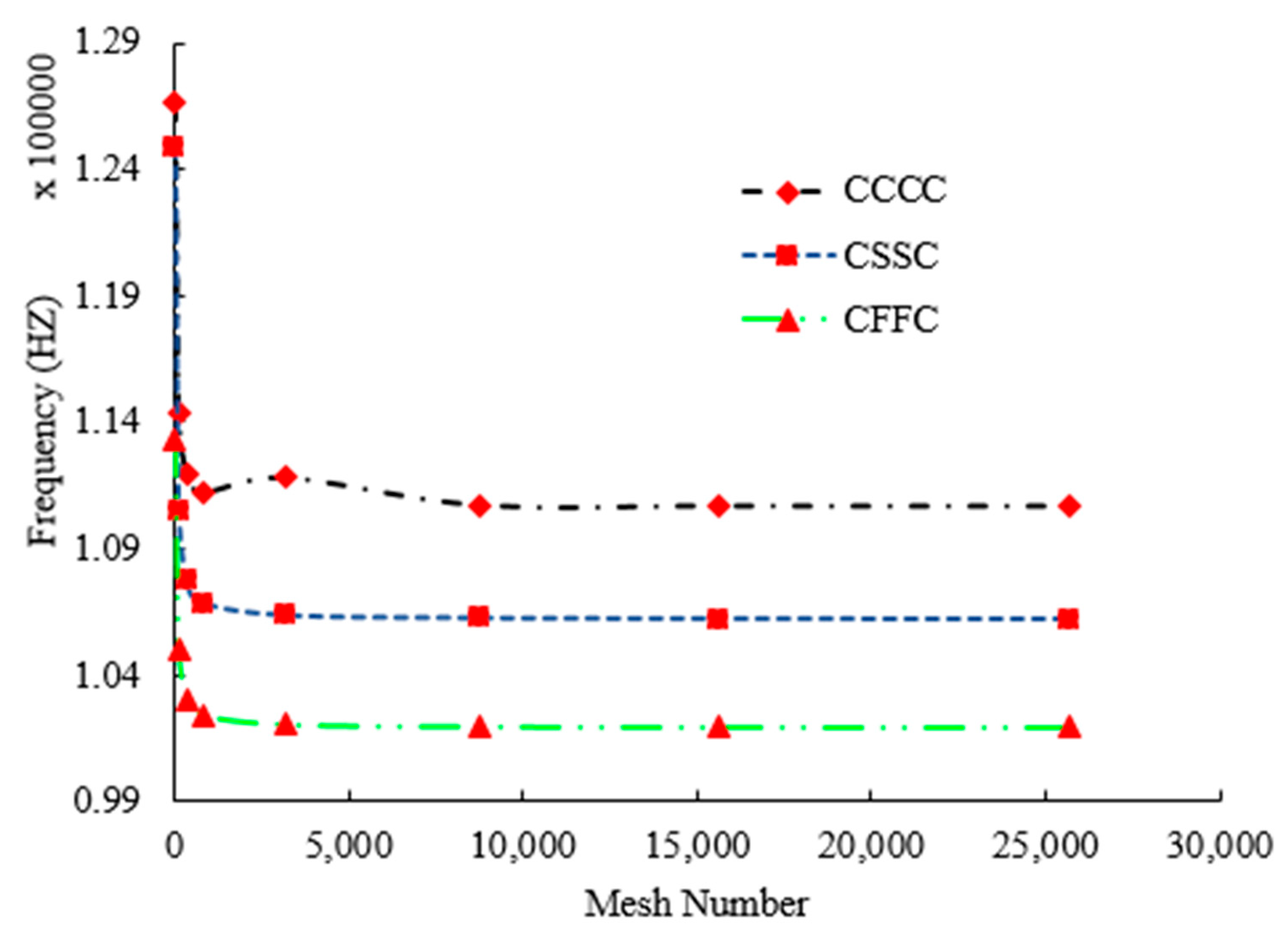
It is well known that if we want to have an accurate finite element (FE) model, we should pay attention to the mesh convergency [75,79,80]. For this matter, the number of elements is increased as long as the natural frequency of the structure does not have any change and the optimum number of elements is selected. According to Figure 2, the convergency condition appears when there are more than 13,000 elements.
A validation study between the numerical results and finite element outcomes is presented in Table 5. The maximum relative discrepancies between the numerical and finite element model (FEM) result is less than 4%. In addition, it can be seen in Table 3 that the best GPL pattern in the frequency issue of the structure is pattern 3, and the more rigid structure will be a reason for boosting the frequency of the GPLRC panel.

4. Results

The material properties of the GPL are summarized in Table 6. It was reported that the material properties of epoxy are functions of temperature T. Therefore, Young’s modulus, shear modulus, and thermal expansion coefficients of epoxy are also functions of temperature T [109]. Poly referred to as PMMA, is selected for the epoxy, and the material properties of which are assumed to be ρ M = 1150 kg/m3, ν M = 0.34, α M = 45 ( 1 + 0.0005 Δ T ) × 10 6 / K , and E M = (3.52 0.0034T) GPa, in which T = T0 +   Δ T (as mentioned earlier T0 is room temperature).
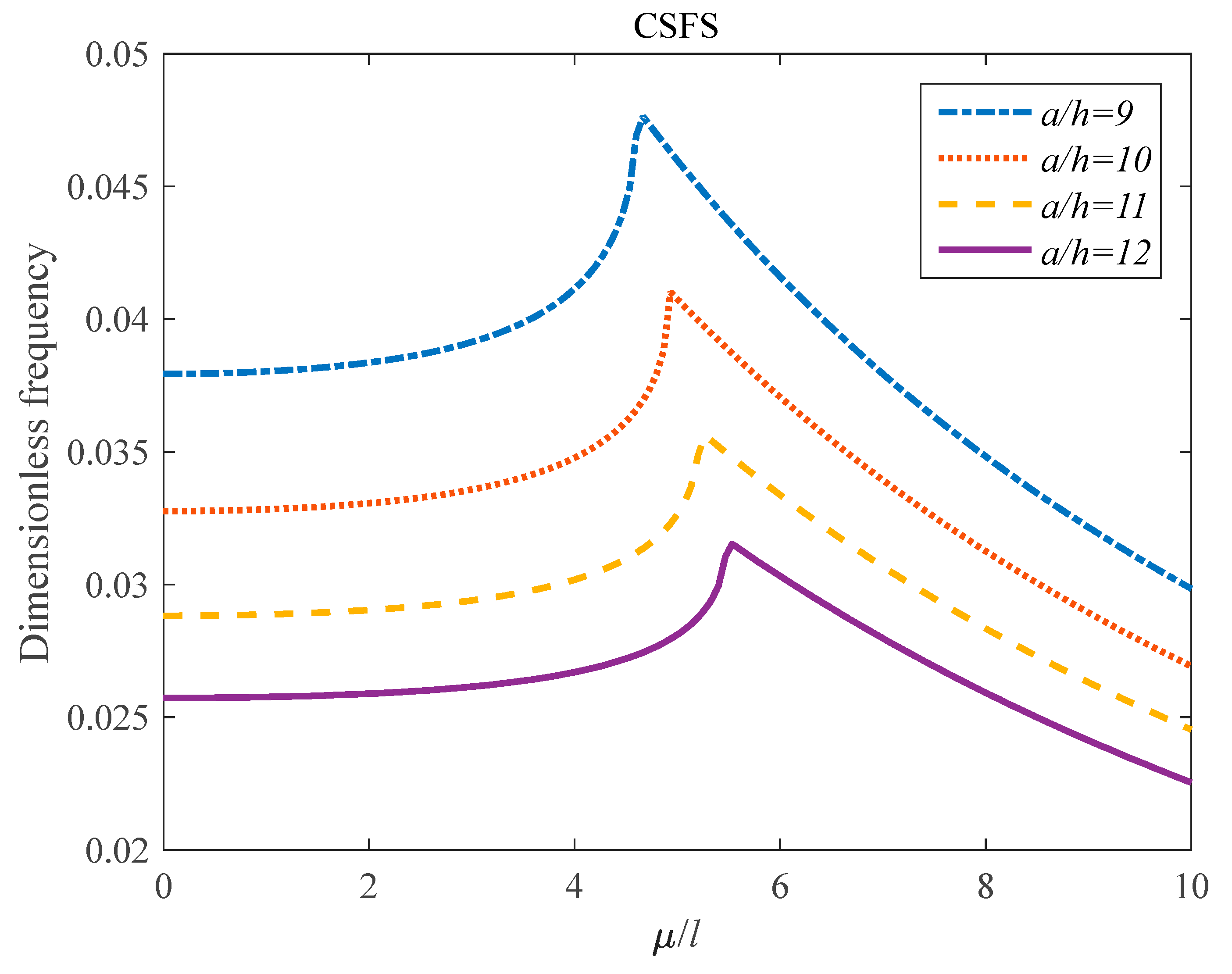
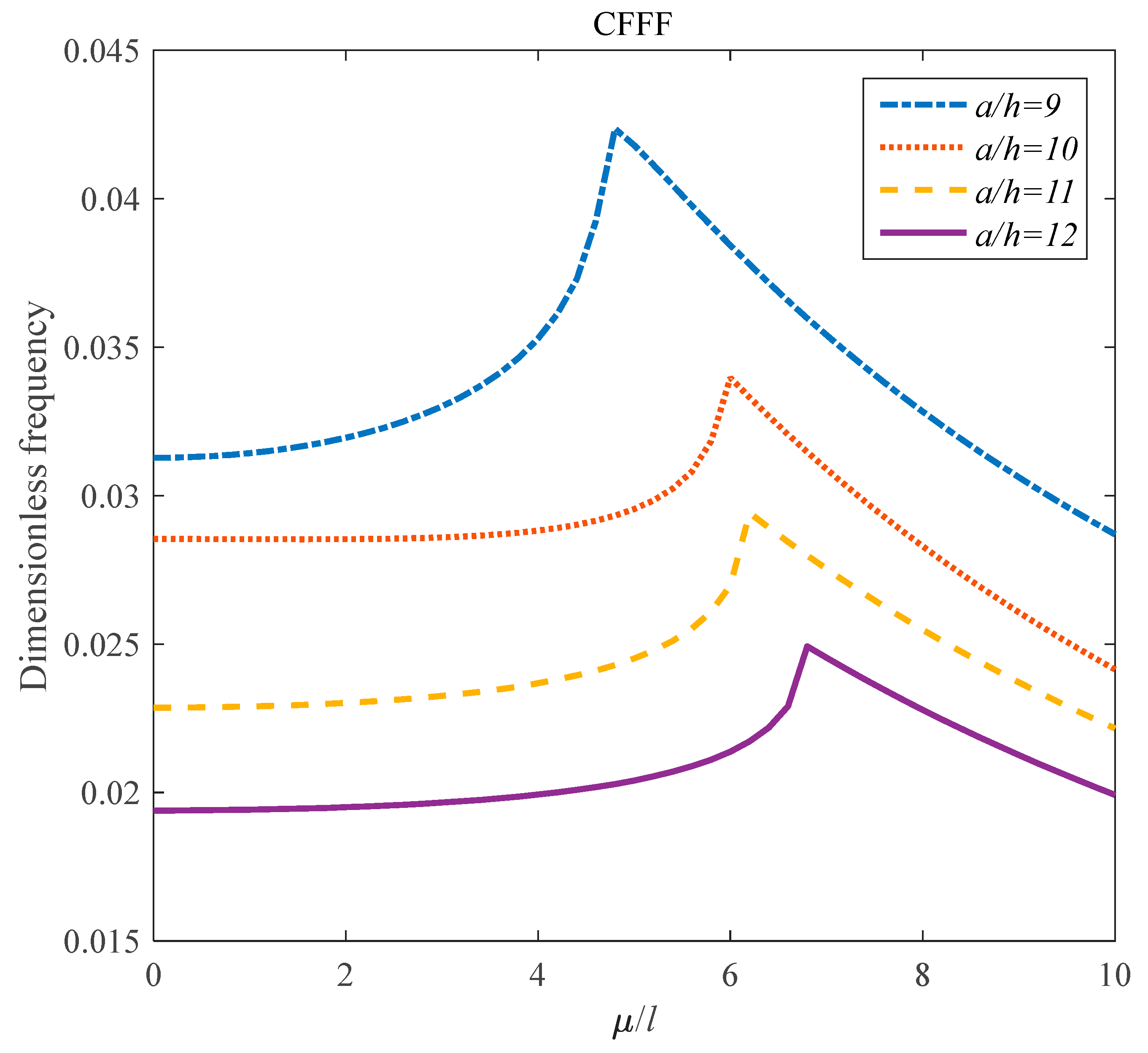
Furthermore, the dimensions of the GPL are assumed to be l G P L = 2.5 μ m , W G P L = 1.5 μ m , and h G P L = 1.5 nm . In the current study, we consider the width of the panel equal to 20 μ m. Figure 3, Figure 4, Figure 5 and Figure 6 face us with exposure about the influences of smaller aspect ratio (a/h) and nonlocal parameter to thickness ratio ( μ / h ) on the vibration response of the structure subjected to the SSSS, CCCC, CSFS, and CFFF boundary conditions.
According to Figure 3 and Figure 4, for CCCC and SSSS boundary conditions, by enhancing the μ / h parameter, the frequency response of the GPLRC panel decreases exponentially. An impressive result is that the impact of the a/h parameter on the frequency of the system is dependent on the value of the nonlocal parameter. For a better understanding, there is an indirect effect from a/h on the dynamics of the panel, and this phenomenon is more intense in the bigger value of the nonlocal parameter. Figure 5 and Figure 6 present that for CSFS and CFFF boundary conditions. First, it can be seen that an increment in the nonlocal parameter leads to an enhancement in the natural frequency of the structure, as long as a maximum point appears. Then, an indirect relation between the μ / h parameter and natural frequency of the structure can be seen. For more detail, at the lower value of the μ / h parameter, there is a direct relation between it and natural frequency, but at the higher value, this relation changes from direct to indirect. Also, for CSFS and CFFF boundary conditions, there is an indirect effect of the a/h parameter on the dynamic response of the panel.
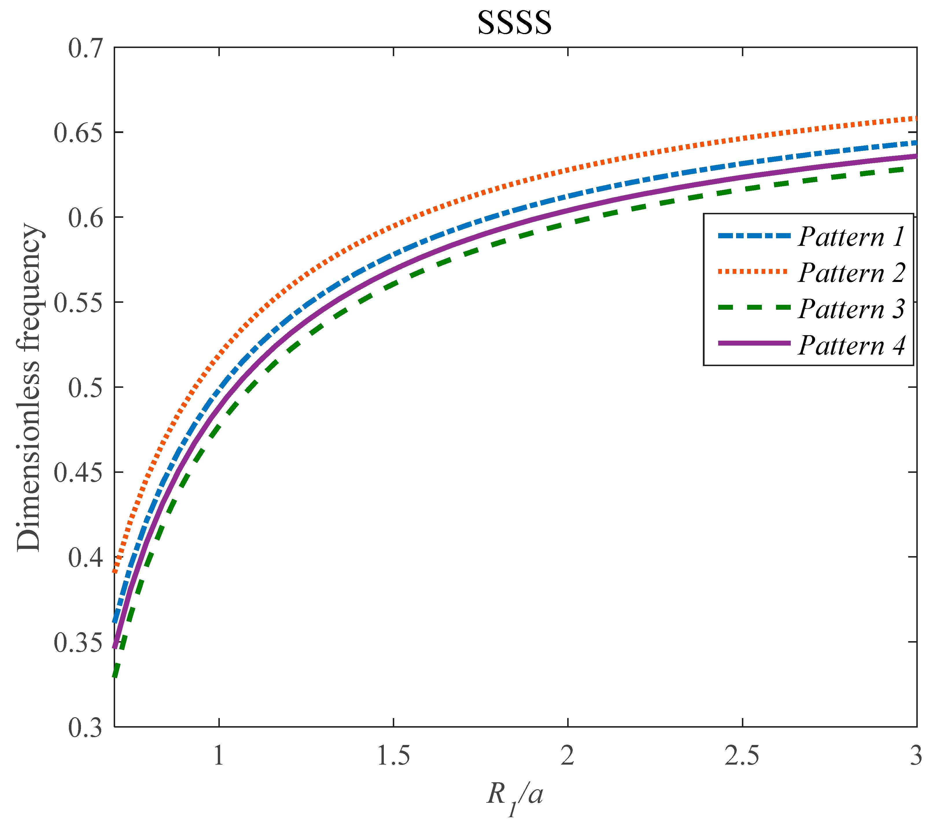
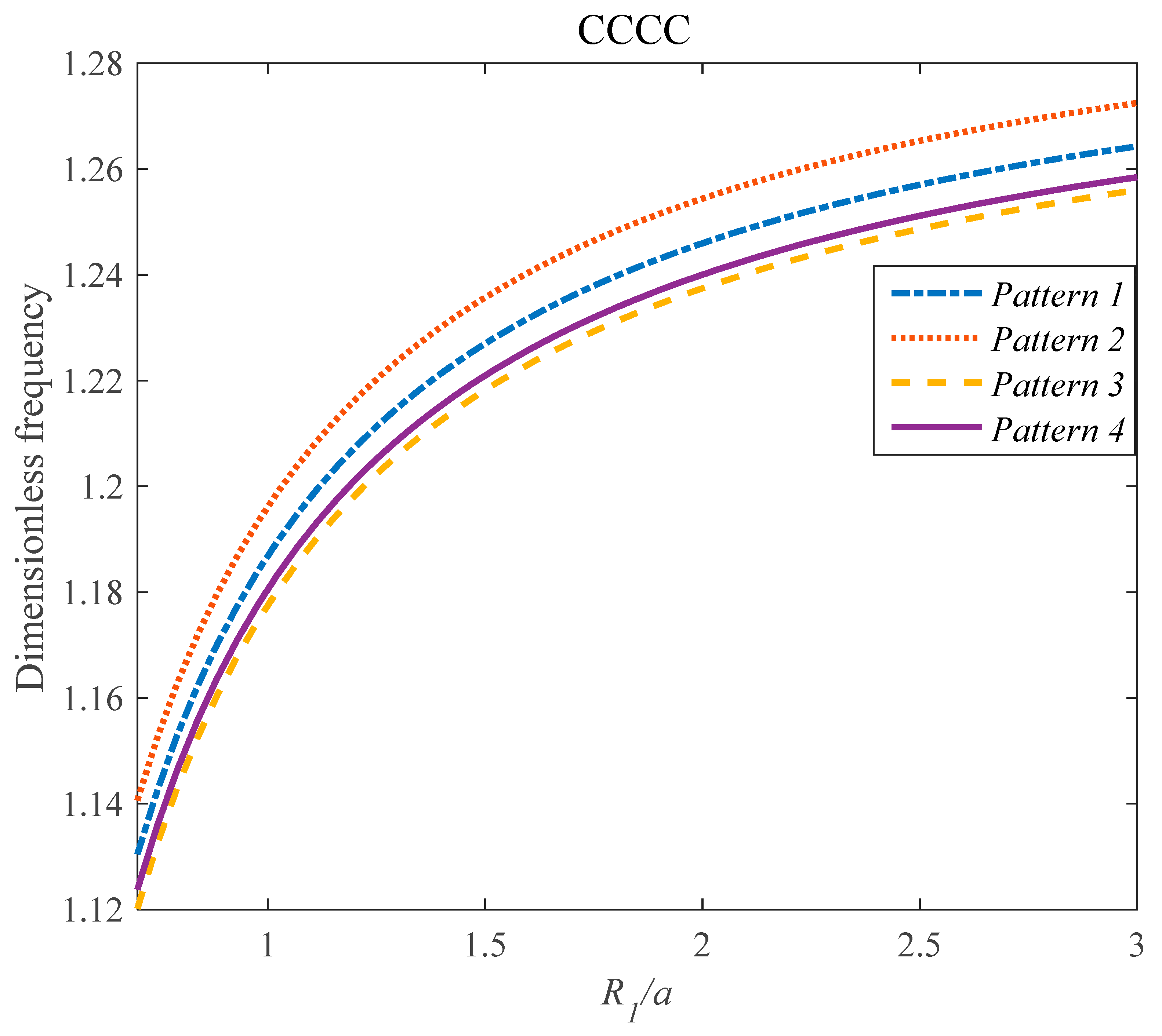
The influences of different graphene distribution patterns and R 1 / a on the frequency of the structure subjected to the (SSSS), (CSFS) and (CCCC) boundary conditions are presented in Figure 7, Figure 8, and Figure 9.
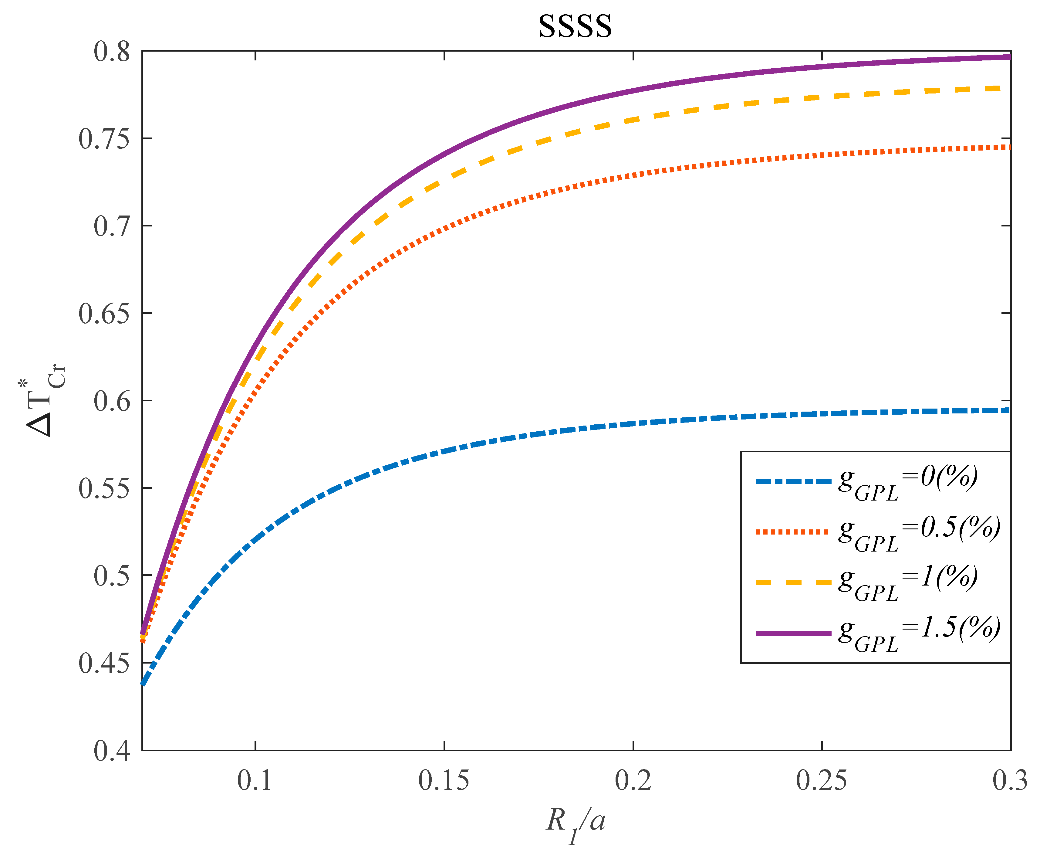
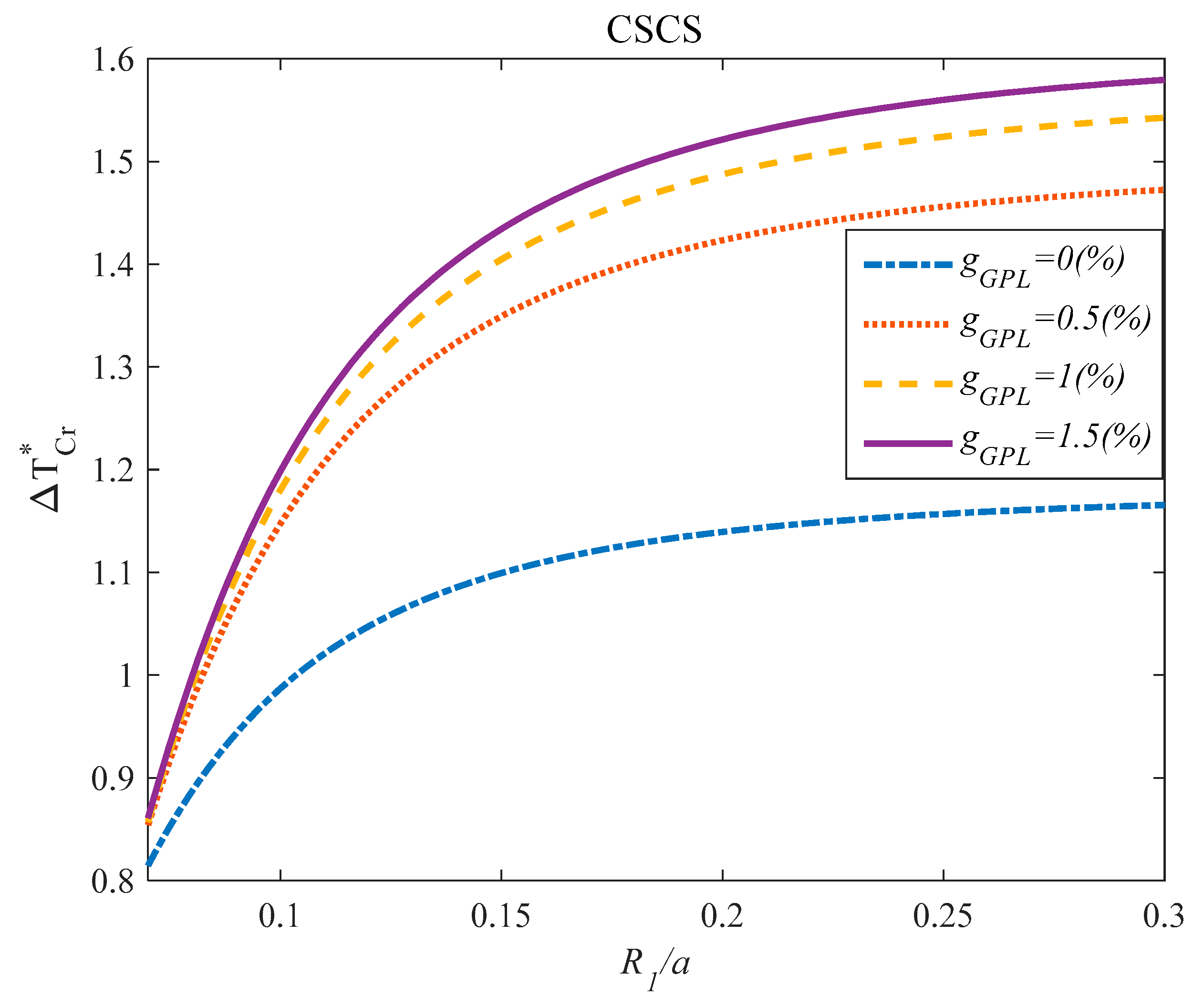
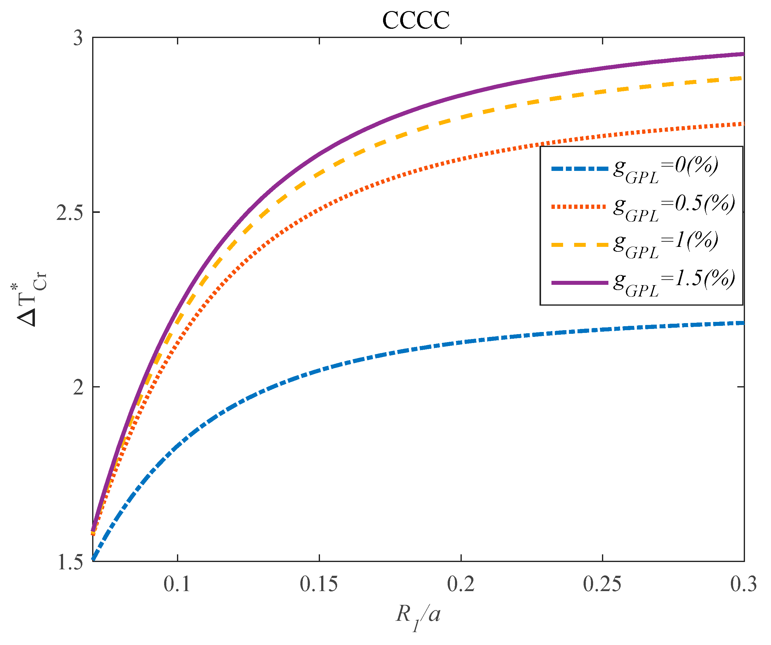
When pattern 2 and pattern 3 are employed to reinforce the structure, the structure encounters the highest and lowest dimensionless frequency, respectively. This behavior stems from the mathematical function, which was presented in the previous section. The alteration of the critical temperature ( Δ T C r ) based on the changes of R 1 / a for different values of g G P L and various types of boundary conditions are presented in Figure 10, Figure 11, and Figure 12.
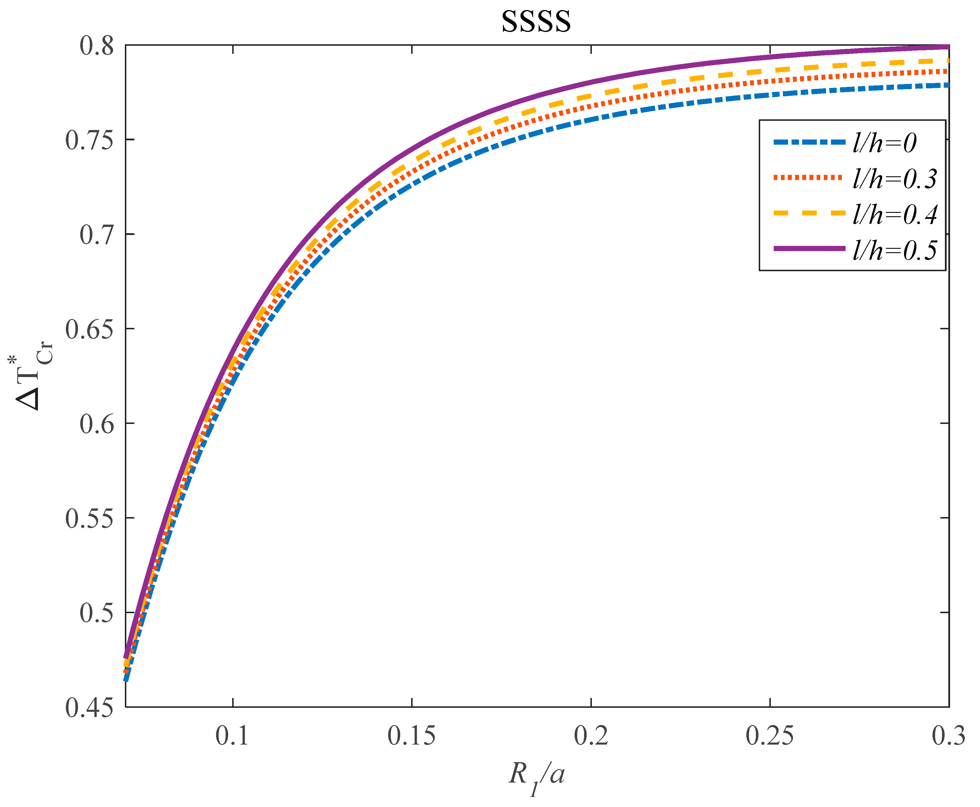
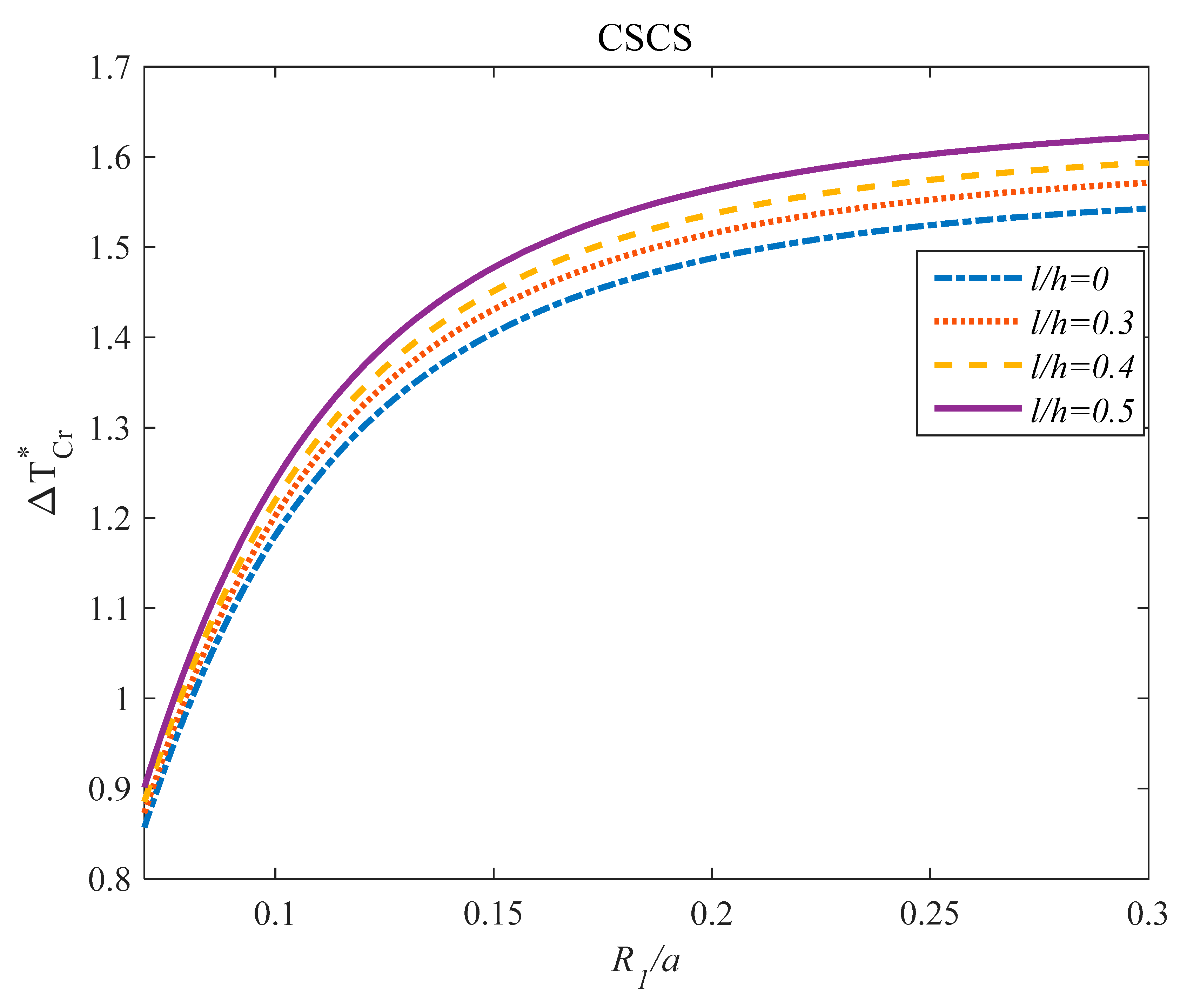
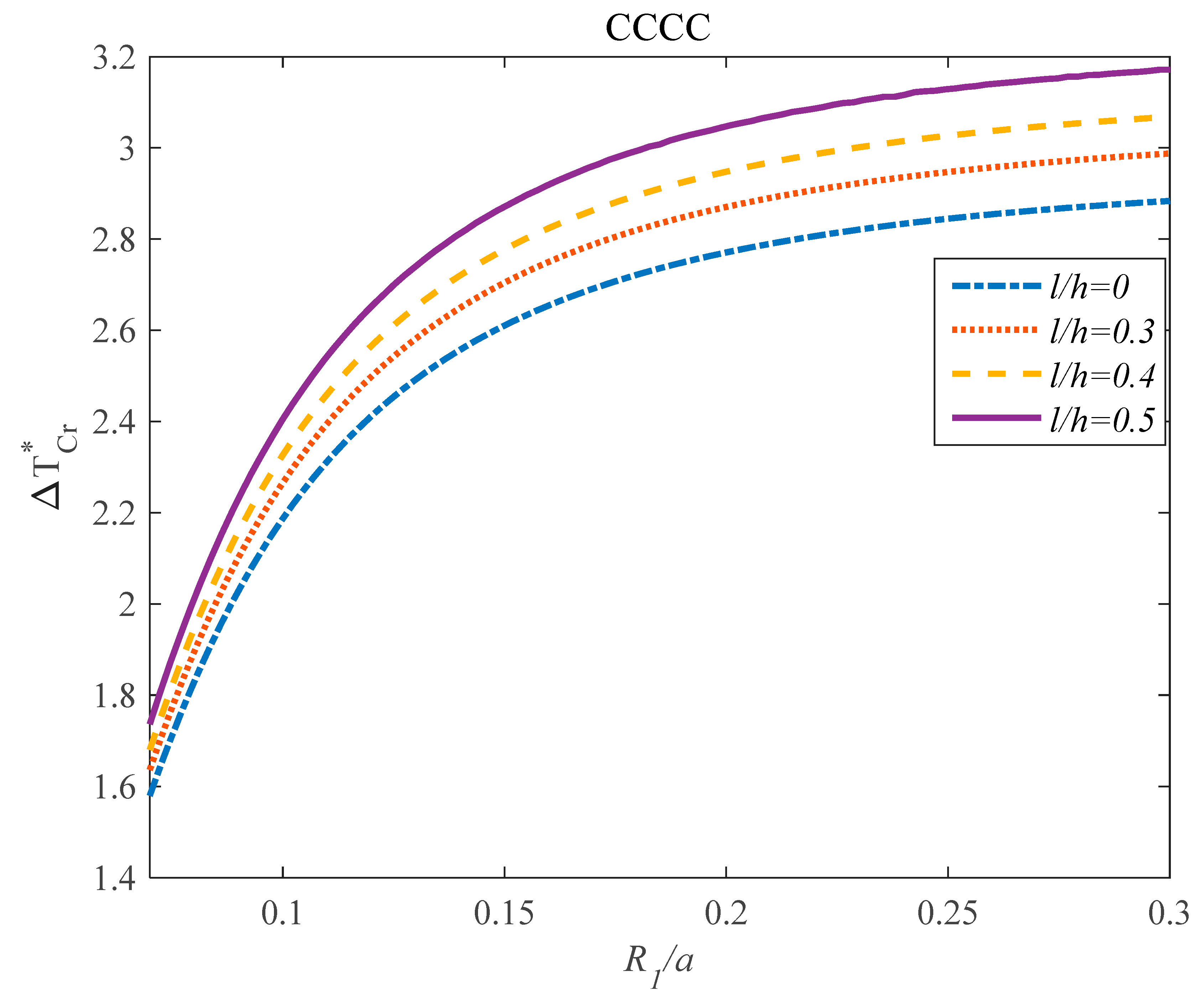
As expected, g G P L plays an important role and has a direct influence on the static behavior of the structure. As can be observed from figures, an increment in the R 1 / a parameter can be seen to exponentially increase in the buckling load at the lower value of the R 1 / a . While this trend changes at the higher values of the R 1 / a , it means at the higher values of the R 1 / a , there are no considerable changes in the temperature due to enhancement in the R 1 / a parameter. It should be noted that the effect of the g G P L parameter on the critical temperature is more noticeable at the higher values of R 1 / a compared to at the lower value of that parameter. In another work, by increasing the R 1 / a parameter, the panel tends to be plate without any imperfection. Thus, the dimensionless critical temperature increases. Figure 13, Figure 14, and Figure 15 indicate the influences of the length scale (l/h) and R 1 / a of the panel on the vibrational characteristics of the structure for various types of boundary conditions such as SSSS, CSSS, and CCCC.
It can be observed from Figure 13, Figure 14, and Figure 15 that l/h and R 1 / a parameters have direct influences on the critical temperature of the GPLRC panel. For better comprehension, an increment in the length scale and R 1 / a parameters provide an increase in the critical temperature of the GPLRC panel. Also, the influences of the length scale parameter on the critical temperature are affected by the R 1 / a parameter. Furthermore, the influence of the l/h parameter on the critical temperature is more considerable at the higher value of R 1 / a in comparison with the lower ones. Additionally, at the higher value of this parameter, the critical temperature does not have any significant change by increasing the R 1 / a parameter.

5. Conclusions

In this study, critical temperature and frequency characteristics of the panel in the thermal environment using NSGT and 2D-GDQM were investigated. The equations of our mathematical model for the panel were formulated with Hamilton’s principle. The novelty of the current study was in considering the effects of the thermal environment, various boundary conditions, and size effects on the frequency and critical temperature of the GPLRC panel. For more verification, a finite element model was presented using the finite element package to simulate the response of the current structure. The results created from a finite element simulation illustrates a close agreement with the numerical method results. Based on the results of this work can claim the following:
The effects of the R 1 / a parameter on the frequency response of the GPLRC panel was dependent on the values of the l/h parameter.
The dynamic stability of the system, unlike static stability, could be affected by the nonlocal parameter indirectly.
At the high value of g G P L the effect of the μ / h on the dimensionless frequency of the composite panel was much more remarkable in comparison with the low value of it.
The effect of the g G P L parameter on the critical temperature of the structures was hardly dependent on the values of the R 1 / a parameter.

Author Contributions

Conceptualization A.A., K.H.S. and M.S.; formal analysis K.H.S. and M.H.; writing—original, A.A., M.S. and M.S.H.A.-F.; writing—review M.S.H.A.-F. and G.C.; visualization M.S.H.A.-F. and G.C. All authors have read and agreed to the published version of the manuscript.

Funding

National Natural Science Foundation of China (51805475, 51675148, 51275141, 51305113) and Islamic Azad University.

Conflicts of Interest

The authors declare no conflict of interest.

Appendix A

The first variation of kinetic energy can be achieved as:
δ K = 0 a 0 b [ ( I 0 2 u 0 t 2 I 1 2 ϕ x t 2 + I 3 c 1 ( 2 ϕ x t 2 + 3 w 0 t 2 x ) ) δ u 0 + ( I 1 2 u 0 t 2 I 2 2 ϕ x t 2 + I 4 c 1 ( 2 ϕ x t 2 + 3 w t 2 x ) ) δ ϕ x + ( c 1 I 3 2 u 0 t 2 + c 1 I 4 2 ϕ x t 2 I 6 c 1 2 ( 2 ϕ x t 2 + 3 w t 2 x ) ) δ ϕ x + ( c 1 I 3 3 u 0 x t 2 c 1 I 4 3 ϕ x x t 2 + I 6 c 1 2 ( 3 ϕ x x t 2 + 4 w t 2 x 2 ) ) δ w 0 ( I 0 2 v 0 t 2 I 1 2 ϕ y t 2 + I 3 c 1 ( 2 ϕ y t 2 + 3 w 0 t 2 y ) ) δ v 0 + ( I 1 2 v 0 t 2 I 2 2 ϕ y t 2 + I 4 c 1 ( 2 ϕ y t 2 + 3 w t 2 y ) ) δ ϕ y + ( c 1 I 3 2 v 0 t 2 + c 1 I 4 2 ϕ y t 2 I 6 c 1 2 ( 2 ϕ y t 2 + 3 w t 2 y ) ) δ ϕ y + ( c 1 I 3 3 v 0 y t 2 c 1 I 4 3 ϕ y y t 2 + I 6 c 1 2 ( 3 ϕ y y t 2 + 4 w t 2 y 2 ) ) δ w 0 + ( I 0 2 w 0 t 2 ) δ w 0 ]   d A
in which
{ I i } = h / 2 h / 2 ρ { z i } ( 1 + z R 1 ) ( 1 + z R 2 ) d z ,         i = 1 : 6
The parameters that are used in Equation (10) can be formulated as follows:
{ N x y , N y y , N x x } = z { σ x y , σ y y , σ x x } d z { M x y , M y y , M x x } = z { σ x y , σ y y , σ x x } × z d z { P x y , P y y , P x x } = z { σ x y , σ y y , σ x x } × z 3 d z { Q y z , Q x z } = z { σ x y , σ x z } d z , { S y z , S x z } = z { σ x y , σ x z } × z 2 d z
where
N x x = A 11 u 0 x + B 11 ϕ x x D 11 c 1 ( ϕ x x + 2 w 0 x 2 ) + A 12 v 0 y + B 12 ϕ y y D 12 c 1 ( ϕ y y + 2 w 0 y 2 ) A 11 w 0 R 1 A 12 w 0 R 2 , N y y = A 22 v 0 y + B 22 ϕ y y D 22 c 1 ( ϕ y y + 2 w 0 y 2 ) + A 12 u 0 x + B 12 ϕ x x D 12 c 1 ( ϕ x x + 2 w 0 x 2 ) A 22 w 0 R 2 A 12 w 0 R 1 , N x y = A 44 u 0 y + A 44 v 0 x + B 44 ( ϕ x y + ϕ y x ) D 44 c 1 ( ϕ x y + ϕ y x + 2 2 w 0 x y ) , M x x = B 11 u 0 x + C 11 ϕ x x E 11 c 1 ( ϕ x x + 2 w 0 x 2 ) B 11 w 0 R 1 + B 12 v 0 y + C 12 ϕ y y E 12 c 1 ( ϕ y y + 2 w 0 y 2 ) B 12 w 0 R 2 , M y y = B 22 v 0 y + C 22 ϕ y y E 22 c 1 ( ϕ y y + 2 w 0 y 2 ) B 22 w 0 R 2 B 12 w 0 R 1 + B 12 u 0 x + C 12 ϕ x x E 12 c 1 ( ϕ x x + 2 w 0 x 2 ) , M x y = B 44 u 0 y + B 44 v 0 x + C 44 ( ϕ x y + ϕ y x ) E 44 c 1 ( ϕ x y + ϕ y x + 2 2 w 0 x y ) p x x = D 11 u 0 x + E 11 ϕ x x G 11 c 1 ( ϕ x x + 2 w 0 x 2 ) D 11 w 0 R 1 D 12 w 0 R 2 + D 12 v 0 y + E 12 ϕ y y G 12 c 1 ( ϕ y y + 2 w 0 y 2 ) , p y y = D 22 v 0 y + E 22 ϕ y y G 22 c 1 ( ϕ y y + 2 w 0 y 2 ) D 12 w 0 R 1 + D 12 u 0 x + E 12 ϕ x x G 12 c 1 ( ϕ x x + 2 w 0 x 2 ) D 22 w 0 R 2 . p x y = D 44 u 0 y + D 44 v 0 x + E 44 ( ϕ x y + ϕ y x ) G 44 c 1 ( ϕ x y + ϕ y x + 2 2 w 0 x y ) , Q x z = ( A 55 3 C 55 c 1 ) ( ϕ x + w 0 x ) ,   S x z = ( C 55 3 E 55 c 1 ) ( ϕ x + w 0 x ) ,   Q y z = ( A 66 3 C 66 c 1 ) ( ϕ y + w 0 y ) ,   S y z = ( C 66 3 E 66 c 1 ) ( ϕ y + w 0 y ) .
where:
{ A 11 , B 11 , C 11 , D 11 , E 11 , F 11 , G 11 } = h / 2 h / 2 Q 11 × { 1 , z , z 2 , z 3 , z 4 , z 5 , z 6 } × ( 1 + z / R 1 ) × ( 1 + z / R 2 ) d z , { A 12 , B 12 , C 12 , D 12 , E 12 , F 12 , G 12 } = h / 2 h / 2 Q 12 × { 1 , z , z 2 , z 3 , z 4 , z 5 , z 6 } × ( 1 + z / R 1 ) × ( 1 + z / R 2 ) d z , { A 22 , B 22 , C 22 , D 22 , E 22 , F 22 , G 22 } = h / 2 h / 2 Q 22 × { 1 , z , z 2 , z 3 , z 4 , z 5 , z 6 } × ( 1 + z / R 1 ) × ( 1 + z / R 2 ) d z , { A 44 , B 44 , C 44 , D 44 , E 44 } = h / 2 h / 2 Q 44 × { 1 , z , z 2 , z 3 , z 4 } × ( 1 + z / R 1 ) × ( 1 + z / R 2 ) d z , { A 55 , B 55 , C 55 , D 55 , E 55 } = h / 2 h / 2 Q 55 × { 1 , z , z 2 , z 3 , z 4 } × ( 1 + z / R 1 ) × ( 1 + z / R 2 ) d z , { A 66 , B 66 , C 66 , D 66 , E 66 } = h / 2 h / 2 Q 66 × { 1 , z , z 2 , z 3 , z 4 } × ( 1 + z / R 1 ) × ( 1 + z / R 2 ) d z .
The governing equations can be derived as below:
δ u 0 : ( 1 2 l 2 ) ( N x x x + N x y y ) = ( 1 2 μ 2 ) ( I 0 2 u 0 t 2 + I 1 2 ϕ x t 2 I 3 c 1 ( 2 ϕ x t 2 + 3 w 0 t 2 x ) ) , δ v 0 : ( 1 2 l 2 ) ( N y y y + N x y x ) = ( 1 2 μ 2 ) ( I 0 2 v 0 t 2 + I 1 2 ϕ y t 2 I 3 c 1 ( 2 ϕ y t 2 + 3 w 0 t 2 y ) ) , δ w 0 : ( 1 2 l 2 ) ( c 1 2 P x x x 2 + c 1 2 P y y y 2 + 2 c 1 2 P x y x y + Q x z x 3 c 1 S x z x + Q y z y 3 c 1 S y z y [ N x x R 1 + ( 2 N x x x 2 ) ] [ N y y R 2 + ( 2 N y y y 2 ) ] + 2 2 N x y x y N 1 T 2 w 0 x 2 N 2 T 2 w 0 y 2 ) = ( 1 2 μ 2 ) ( c 1 I 3 3 u 0 x t 2 + c 1 I 4 3 ϕ x x t 2 I 6 c 1 2 ( 3 ϕ x x t 2 + 4 w t 2 x 2 ) + c 1 I 3 3 v 0 y t 2 + c 1 I 4 3 ϕ y y t 2 I 6 c 1 2 ( 3 ϕ y y t 2 + 4 w t 2 y 2 ) + ( I 0 2 w 0 t 2 ) ) δ ϕ x : ( 1 2 l 2 ) ( M x x x c 1 P x x x + M x y y c 1 P x y y Q x z + 3 c 1 S x z ) = ( 1 2 μ 2 ) ( I 1 2 u 0 t 2 + I 2 2 ϕ x t 2 I 4 c 1 ( 2 ϕ x t 2 + 3 w t 2 x ) c 1 I 3 2 u 0 t 2 c 1 I 4 2 ϕ x t 2 + I 6 c 1 2 ( 2 ϕ x t 2 + 3 w t 2 x ) ) δ ϕ y : ( 1 2 l 2 ) ( M y y y c 1 P y y y + M x y x c 1 P x y x Q y z + 3 c 1 S y z ) = ( 1 2 μ 2 ) ( I 1 2 v 0 t 2 + I 2 2 ϕ y t 2 I 4 c 1 ( 2 ϕ y t 2 + 3 w t 2 y ) c 1 I 3 2 v 0 t 2 c 1 I 4 2 ϕ y t 2 + I 6 c 1 2 ( 2 ϕ y t 2 + 3 w t 2 y ) )
It is worth mentioning that 2 = 2 / x 2 + 2 / y 2 .

References

  1. Zhao, X.; Li, D.; Yang, B.; Ma, C.; Zhu, Y.; Chen, H. Feature selection based on improved ant colony optimization for online detection of foreign fiber in cotton. Appl. Soft Comput. 2014, 24, 585–596. [Google Scholar] [CrossRef]
  2. Wang, M.; Chen, H. Chaotic multi-swarm whale optimizer boosted support vector machine for medical diagnosis. Appl. Soft Comput. 2020, 88, 105946. [Google Scholar] [CrossRef]
  3. Zhao, X.; Zhang, X.; Cai, Z.; Tian, X.; Wang, X.; Huang, Y.; Chen, H.; Hu, L. Chaos enhanced grey wolf optimization wrapped ELM for diagnosis of paraquat-poisoned patients. Comput. Biol. Chem. 2019, 78, 481–490. [Google Scholar] [CrossRef] [PubMed]
  4. Xu, X.; Chen, H.-L. Adaptive computational chemotaxis based on field in bacterial foraging optimization. Soft Comput. 2014, 18, 797–807. [Google Scholar] [CrossRef]
  5. Shen, L.; Chen, H.; Yu, Z.; Kang, W.; Zhang, B.; Li, H.; Yang, B.; Liu, D. Evolving support vector machines using fruit fly optimization for medical data classification. Knowl. Based Syst. 2016, 96, 61–75. [Google Scholar] [CrossRef]
  6. Wang, M.; Chen, H.; Yang, B.; Zhao, X.; Hu, L.; Cai, Z.; Huang, H.; Tong, C. Toward an optimal kernel extreme learning machine using a chaotic moth-flame optimization strategy with applications in medical diagnoses. Neurocomputing 2017, 267, 69–84. [Google Scholar] [CrossRef]
  7. Xu, Y.; Chen, H.; Luo, J.; Zhang, Q.; Jiao, S.; Zhang, X. Enhanced Moth-flame optimizer with mutation strategy for global optimization. Inf. Sci. 2019, 492, 181–203. [Google Scholar] [CrossRef]
  8. Chen, H.; Zhang, Q.; Luo, J.; Xu, Y.; Zhang, X. An enhanced Bacterial Foraging Optimization and its application for training kernel extreme learning machine. Appl. Soft Comput. 2020, 86, 105884. [Google Scholar] [CrossRef]
  9. Nadri, S.; Xie, L.; Jafari, M.; Alijabbari, N.; Cyberey, M.E.; Barker, N.S.; Lichtenberger, A.W.; Weikle, R.M. A 160 GHz frequency Quadrupler based on heterogeneous integration of GaAs Schottky diodes onto silicon using SU-8 for epitaxy transfer. In Proceedings of the 2018 IEEE/MTT-S International Microwave Symposium-IMS, Philadelphia, PA, USA, 10–15 June 2018; pp. 769–772. [Google Scholar]
  10. Shi, G.; Araby, S.; Gibson, C.T.; Meng, Q.; Zhu, S.; Ma, J. Graphene Platelets and Their Polymer Composites: Fabrication, Structure, Properties, and Applications. Adv. Funct. Mater. 2018, 28, 1706705. [Google Scholar] [CrossRef]
  11. Sun, J.; Zhao, J. Multi-layer graphene reinforced nano-laminated WC-Co composites. Mater. Sci. Eng. A 2018, 723, 1–7. [Google Scholar] [CrossRef]
  12. Rafiee, M.A.; Rafiee, J.; Wang, Z.; Song, H.; Yu, Z.-Z.; Koratkar, N. Enhanced mechanical properties of nanocomposites at low graphene content. Acs Nano 2009, 3, 3884–3890. [Google Scholar] [CrossRef] [PubMed]
  13. Safarpour, H.; Ghanizadeh, S.A.; Habibi, M. Wave propagation characteristics of a cylindrical laminated composite nanoshell in thermal environment based on the nonlocal strain gradient theory. Eur. Phys. J. Plus 2018, 133, 532. [Google Scholar] [CrossRef]
  14. Zeighampour, H.; Beni, Y.T.; Karimipour, I. Material length scale and nonlocal effects on the wave propagation of composite laminated cylindrical micro/nanoshells. Eur. Phys. J. Plus 2017, 132, 503. [Google Scholar] [CrossRef]
  15. Sahmani, S.; Fattahi, A.; Ahmed, N. Analytical mathematical solution for vibrational response of postbuckled laminated FG-GPLRC nonlocal strain gradient micro-/nanobeams. Eng. Comput. 2019, 35, 1173–1189. [Google Scholar] [CrossRef]
  16. Shokrgozar, A.; Ghabussi, A.; Ebrahimi, F.; Habibi, M.; Safarpour, H. Viscoelastic dynamics and static responses of a graphene nanoplatelets-reinforced composite cylindrical microshell. Mech. Based Des. Struct. Mach. 2020, 1–28. [Google Scholar] [CrossRef]
  17. Ebrahimi, F.; Supeni, E.E.B.; Habibi, M.; Safarpour, H. Frequency characteristics of a GPL-reinforced composite microdisk coupled with a piezoelectric layer. Eur. Phys. J. Plus 2020, 135, 144. [Google Scholar]
  18. Ebrahimi, F.; Hashemabadi, D.; Habibi, M.; Safarpour, H. Thermal buckling and forced vibration characteristics of a porous GNP reinforced nanocomposite cylindrical shell. Microsyst. Technol. 2020, 26, 461–473. [Google Scholar] [CrossRef]
  19. Moayedi, H.; Aliakbarlou, H.; Jebeli, M.; Noormohammadi Arani, O.; Habibi, M.; Safarpour, H.; Foong, L. Thermal buckling responses of a graphene reinforced composite micropanel structure. Int. J. Appl. Mech. 2020, 12, 2050010. [Google Scholar] [CrossRef]
  20. Shokrgozar, A.; Safarpour, H.; Habibi, M. Influence of system parameters on buckling and frequency analysis of a spinning cantilever cylindrical 3D shell coupled with piezoelectric actuator. Proc. Inst. Mech. Eng. Part C J. Mech. Eng. Sci. 2020, 234, 512–529. [Google Scholar] [CrossRef]
  21. Ghabussi, A.; Ashrafi, N.; Shavalipour, A.; Hosseinpour, A.; Habibi, M.; Moayedi, H.; Babaei, B.; Safarpour, H. Free vibration analysis of an electro-elastic GPLRC cylindrical shell surrounded by viscoelastic foundation using modified length-couple stress parameter. Mech. Based Des. Struct. Mach. 2019, 1–25. [Google Scholar] [CrossRef]
  22. Habibi, M.; Mohammadi, A.; Safarpour, H.; Ghadiri, M. Effect of porosity on buckling and vibrational characteristics of the imperfect GPLRC composite nanoshell. Mech. Based Des. Struct. Mach. 2019, 1–30. [Google Scholar] [CrossRef]
  23. Habibi, M.; Mohammadi, A.; Safarpour, H.; Shavalipour, A.; Ghadiri, M. Wave propagation analysis of the laminated cylindrical nanoshell coupled with a piezoelectric actuator. Mech. Based Des. Struct. Mach. 2019, 1–19. [Google Scholar] [CrossRef]
  24. Ebrahimi, F.; Mohammadi, K.; Barouti, M.M.; Habibi, M. Wave propagation analysis of a spinning porous graphene nanoplatelet-reinforced nanoshell. Waves Random Complex Media 2019, 1–27. [Google Scholar] [CrossRef]
  25. Habibi, M.; Taghdir, A.; Safarpour, H. Stability analysis of an electrically cylindrical nanoshell reinforced with graphene nanoplatelets. Compos. Part B Eng. 2019, 175, 107125. [Google Scholar] [CrossRef]
  26. Mohammadgholiha, M.; Shokrgozar, A.; Habibi, M.; Safarpour, H. Buckling and frequency analysis of the nonlocal strain–stress gradient shell reinforced with graphene nanoplatelets. J. Vib. Control 2019, 25, 2627–2640. [Google Scholar] [CrossRef]
  27. Ebrahimi, F.; Habibi, M.; Safarpour, H. On modeling of wave propagation in a thermally affected GNP-reinforced imperfect nanocomposite shell. Eng. Comput. 2019, 35, 1375–1389. [Google Scholar] [CrossRef]
  28. Ghanbari, B.; Ghadiri, M.; SafarPour, H. A modified strain gradient shell model for vibration analysis of DWCNT conveying viscous fluid including surface effects. Mech. Based Des. Struct. Mach. 2020, 21, 1–31. [Google Scholar] [CrossRef]
  29. Hashemi, H.R.; Alizadeh, A.A.; Oyarhossein, M.A.; Shavalipour, A.; Makkiabadi, M.; Habibi, M. Influence of imperfection on amplitude and resonance frequency of a reinforcement compositionally graded nanostructure. Waves Random Complex Media 2019, 1–27. [Google Scholar] [CrossRef]
  30. Esmailpoor Hajilak, Z.; Pourghader, J.; Hashemabadi, D.; Sharifi Bagh, F.; Habibi, M.; Safarpour, H. Multilayer GPLRC composite cylindrical nanoshell using modified strain gradient theory. Mech. Based Des. Struct. Mach. 2019, 47, 521–545. [Google Scholar] [CrossRef]
  31. Ebrahimi, F.; Hajilak, Z.E.; Habibi, M.; Safarpour, H. Buckling and vibration characteristics of a carbon nanotube-reinforced spinning cantilever cylindrical 3D shell conveying viscous fluid flow and carrying spring-mass systems under various temperature distributions. Proc. Inst. Mech. Eng. Part C J. Mech. Eng. Sci. 2019, 233, 4590–4605. [Google Scholar] [CrossRef]
  32. Mohammadi, A.; Lashini, H.; Habibi, M.; Safarpour, H. Influence of viscoelastic foundation on dynamic behaviour of the double walled cylindrical inhomogeneous micro shell using MCST and with the aid of GDQM. J. Solid Mech. 2019, 11, 440–453. [Google Scholar]
  33. Habibi, M.; Hashemabadi, D.; Safarpour, H. Vibration analysis of a high-speed rotating GPLRC nanostructure coupled with a piezoelectric actuator. Eur. Phys. J. Plus 2019, 134, 307. [Google Scholar] [CrossRef]
  34. Pourjabari, A.; Hajilak, Z.E.; Mohammadi, A.; Habibi, M.; Safarpour, H. Effect of porosity on free and forced vibration characteristics of the GPL reinforcement composite nanostructures. Comput. Math. Appl. 2019, 77, 2608–2626. [Google Scholar] [CrossRef]
  35. Habibi, M.; Mohammadgholiha, M.; Safarpour, H. Wave propagation characteristics of the electrically GNP-reinforced nanocomposite cylindrical shell. J. Braz. Soc. Mech. Sci. Eng. 2019, 41, 221. [Google Scholar] [CrossRef]
  36. Safarpour, H.; Pourghader, J.; Habibi, M. Influence of spring-mass systems on frequency behavior and critical voltage of a high-speed rotating cantilever cylindrical three-dimensional shell coupled with piezoelectric actuator. J. Vib. Control 2019, 25, 1543–1557. [Google Scholar] [CrossRef]
  37. Safarpour, M.; Ghabussi, A.; Ebrahimi, F.; Habibi, M.; Safarpour, H. Frequency characteristics of FG-GPLRC viscoelastic thick annular plate with the aid of GDQM. Thin-Walled Struct. 2020, 150, 106683. [Google Scholar] [CrossRef]
  38. Safarpour, M.; Ebrahimi, F.; Habibi, M.; Safarpour, H. On the nonlinear dynamics of a multi-scale hybrid nanocomposite disk. Eng. Comput. 2020, 1–20. [Google Scholar] [CrossRef]
  39. Moayedi, H.; Habibi, M.; Safarpour, H.; Safarpour, M.; Foong, L. Buckling and Frequency Responses of A Graphene Nanoplatelet Reinforced Composite Microdisk. Int. J. Appl. Mech. 2019, 11. [Google Scholar] [CrossRef]
  40. Sahmani, S.; Fattahi, A. Size-dependent nonlinear instability of shear deformable cylindrical nanopanels subjected to axial compression in thermal environments. Microsyst. Technol. 2017, 23, 4717–4731. [Google Scholar] [CrossRef]
  41. Sahmani, S.; Aghdam, M. Nonlocal electrothermomechanical instability of temperature-dependent FGM nanopanels with piezoelectric facesheets. Iran. J. Sci. Technol. Trans. Mech. Eng. 2019, 43, 579–593. [Google Scholar] [CrossRef]
  42. Sahmani, S.; Khandan, A. Size dependency in nonlinear instability of smart magneto-electro-elastic cylindrical composite nanopanels based upon nonlocal strain gradient elasticity. Microsyst. Technol. 2019, 25, 2171–2186. [Google Scholar] [CrossRef]
  43. Sarvestani, H.Y.; Akbarzadeh, A.; Mirabolghasemi, A. Structural analysis of size-dependent functionally graded doubly-curved panels with engineered microarchitectures. Acta Mech. 2018, 229, 2675–2701. [Google Scholar] [CrossRef]
  44. Zhou, S.; Zhang, R.; Zhou, S.; Li, A. Free vibration analysis of bilayered circular micro-plate including surface effects. Appl. Math. Model. 2019, 70, 54–66. [Google Scholar] [CrossRef]
  45. Gholami, R.; Darvizeh, A.; Ansari, R.; Pourashraf, T. Analytical treatment of the size-dependent nonlinear postbuckling of functionally graded circular cylindrical micro-/nano-shells. Iran. J. Sci. Technol. Trans. Mech. Eng. 2018, 42, 85–97. [Google Scholar] [CrossRef]
  46. Mohammadimehr, M.; Emdadi, M.; Afshari, H.; Rousta Navi, B. Bending, buckling and vibration analyses of MSGT microcomposite circular-annular sandwich plate under hydro-thermo-magneto-mechanical loadings using DQM. Int. J. Smart Nano Mater. 2018, 9, 233–260. [Google Scholar] [CrossRef] [Green Version]
  47. Mohammadimehr, M.; Atifeh, S.J.; Rousta Navi, B. Stress and free vibration analysis of piezoelectric hollow circular FG-SWBNNTs reinforced nanocomposite plate based on modified couple stress theory subjected to thermo-mechanical loadings. J. Vib. Control 2018, 24, 3471–3486. [Google Scholar] [CrossRef]
  48. Sajadi, B.; Alijani, F.; Goosen, H.; van Keulen, F. Effect of pressure on nonlinear dynamics and instability of electrically actuated circular micro-plates. Nonlinear Dyn. 2018, 91, 2157–2170. [Google Scholar] [CrossRef] [Green Version]
  49. Wang, Z.-W.; Han, Q.-F.; Nash, D.H.; Liu, P.-Q. Investigation on inconsistency of theoretical solution of thermal buckling critical temperature rise for cylindrical shell. Thin-Walled Struct. 2017, 119, 438–446. [Google Scholar] [CrossRef]
  50. Safarpour, H.; Hajilak, Z.E.; Habibi, M. A size-dependent exact theory for thermal buckling, free and forced vibration analysis of temperature dependent FG multilayer GPLRC composite nanostructures restring on elastic foundation. Int. J. Mech. Mater. Des. 2019, 15, 569–583. [Google Scholar] [CrossRef]
  51. Wang, K.; Wang, B.; Zhang, C. Surface energy and thermal stress effect on nonlinear vibration of electrostatically actuated circular micro-/nanoplates based on modified couple stress theory. Acta Mech. 2017, 228, 129–140. [Google Scholar] [CrossRef]
  52. Mahinzare, M.; Alipour, M.J.; Sadatsakkak, S.A.; Ghadiri, M. A nonlocal strain gradient theory for dynamic modeling of a rotary thermo piezo electrically actuated nano FG circular plate. Mech. Syst. Signal Process. 2019, 115, 323–337. [Google Scholar] [CrossRef]
  53. Mahinzare, M.; Ranjbarpur, H.; Ghadiri, M. Free vibration analysis of a rotary smart two directional functionally graded piezoelectric material in axial symmetry circular nanoplate. Mech. Syst. Signal Process. 2018, 100, 188–207. [Google Scholar] [CrossRef]
  54. Safarpour, H.; Barooti, M.; Ghadiri, M. Influence of Rotation on Vibration Behavior of a Functionally Graded Moderately Thick Cylindrical Nanoshell Considering Initial Hoop Tension. J. Solid Mech. 2019, 11, 254–271. [Google Scholar]
  55. Ebrahimi, F.; Safarpour, H. Vibration analysis of inhomogeneous nonlocal beams via a modified couple stress theory incorporating surface effects. Wind Struct. 2018, 27, 431–438. [Google Scholar]
  56. Mohammadi, K.; Barouti, M.M.; Safarpour, H.; Ghadiri, M. Effect of distributed axial loading on dynamic stability and buckling analysis of a viscoelastic DWCNT conveying viscous fluid flow. J. Braz. Soc. Mech. Sci. Eng. 2019, 41, 93. [Google Scholar] [CrossRef]
  57. SafarPour, H.; Hosseini, M.; Ghadiri, M. Influence of three-parameter viscoelastic medium on vibration behavior of a cylindrical nonhomogeneous microshell in thermal environment: An exact solution. J. Therm. Stresses 2017, 40, 1353–1367. [Google Scholar] [CrossRef]
  58. Safarpour, H.; Mohammadi, K.; Ghadiri, M.; Barooti, M.M. Effect of porosity on flexural vibration of CNT-reinforced cylindrical shells in thermal environment using GDQM. Int. J. Struct. Stab. Dyn. 2018, 18, 1850123. [Google Scholar] [CrossRef]
  59. Safarpour, H.; Mohammadi, K.; Ghadiri, M. Temperature-dependent vibration analysis of a FG viscoelastic cylindrical microshell under various thermal distribution via modified length scale parameter: A numerical solution. J. Mech. Behav. Mater. 2017, 26, 9–24. [Google Scholar] [CrossRef]
  60. SafarPour, H.; Ghanbari, B.; Ghadiri, M. Buckling and free vibration analysis of high speed rotating carbon nanotube reinforced cylindrical piezoelectric shell. Appl. Math. Model. 2019, 65, 428–442. [Google Scholar] [CrossRef]
  61. Shojaeefard, M.; Mahinzare, M.; Safarpour, H.; Googarchin, H.S.; Ghadiri, M. Free vibration of an ultra-fast-rotating-induced cylindrical nano-shell resting on a Winkler foundation under thermo-electro-magneto-elastic condition. Appl. Math. Model. 2018, 61, 255–279. [Google Scholar] [CrossRef]
  62. Ghadiri, M.; Safarpour, H. Free vibration analysis of embedded magneto-electro-thermo-elastic cylindrical nanoshell based on the modified couple stress theory. Appl. Phys. A 2016, 122, 833. [Google Scholar] [CrossRef]
  63. Ghadiri, M.; SafarPour, H. Free vibration analysis of size-dependent functionally graded porous cylindrical microshells in thermal environment. J. Therm. Stresses 2017, 40, 55–71. [Google Scholar] [CrossRef]
  64. Ghadiri, M.; Shafiei, N.; Safarpour, H. Influence of surface effects on vibration behavior of a rotary functionally graded nanobeam based on Eringen’s nonlocal elasticity. Microsyst. Technol. 2017, 23, 1045–1065. [Google Scholar] [CrossRef]
  65. SafarPour, H.; Ghadiri, M. Critical rotational speed, critical velocity of fluid flow and free vibration analysis of a spinning SWCNT conveying viscous fluid. Microfluid. Nanofluid. 2017, 21, 22. [Google Scholar] [CrossRef]
  66. Barooti, M.M.; Safarpour, H.; Ghadiri, M. Critical speed and free vibration analysis of spinning 3D single-walled carbon nanotubes resting on elastic foundations. Eur. Phys. J. Plus 2017, 132, 6. [Google Scholar] [CrossRef]
  67. SafarPour, H.; Mohammadi, K.; Ghadiri, M.; Rajabpour, A. Influence of various temperature distributions on critical speed and vibrational characteristics of rotating cylindrical microshells with modified lengthscale parameter. Eur. Phys. J. Plus 2017, 132, 281. [Google Scholar] [CrossRef]
  68. Ghadiri, M.; Safarpour, H. Free Vibration Analysis of a Functionally Graded Cylindrical Nanoshell Surrounded by Elastic Foundation Based on the Modified Couple Stress Theory. Amirkabir J. Mech. Eng. 2018, 49, 257–260. [Google Scholar]
  69. Song, M.; Kitipornchai, S.; Yang, J. Free and forced vibrations of functionally graded polymer composite plates reinforced with graphene nanoplatelets. Compos. Struct. 2017, 159, 579–588. [Google Scholar] [CrossRef]
  70. De Villoria, R.G.; Miravete, A. Mechanical model to evaluate the effect of the dispersion in nanocomposites. Acta Mater. 2007, 55, 3025–3031. [Google Scholar] [CrossRef]
  71. Karimiasl, M.; Ebrahimi, F.; Vinyas, M. Nonlinear vibration analysis of multiscale doubly curved piezoelectric composite shell in hygrothermal environment. J. Intell. Mater. Syst. Struct. 2019, 30, 1594–1609. [Google Scholar] [CrossRef]
  72. Moayedi, H.; Darabi, R.; Ghabussi, A.; Habibi, M.; Foong, L.K. Weld orientation effects on the formability of tailor welded thin steel sheets. Thin-Walled Struct. 2020, 149, 106669. [Google Scholar] [CrossRef]
  73. Ghazanfari, A.; Soleimani, S.S.; Keshavarzzadeh, M.; Habibi, M.; Assempuor, A.; Hashemi, R. Prediction of FLD for sheet metal by considering through-thickness shear stresses. Mech. Based Des. Struct. Mach. 2019, 1–18. [Google Scholar] [CrossRef]
  74. Alipour, M.; Torabi, M.A.; Sareban, M.; Lashini, H.; Sadeghi, E.; Fazaeli, A.; Habibi, M.; Hashemi, R. Finite element and experimental method for analyzing the effects of martensite morphologies on the formability of DP steels. Mech. Based Des. Struct. Mach. 2019, 1–17. [Google Scholar] [CrossRef]
  75. Hosseini, S.; Habibi, M.; Assempour, A. Experimental and numerical determination of forming limit diagram of steel-copper two-layer sheet considering the interface between the layers. Modares Mech. Eng. 2018, 18, 174–181. [Google Scholar]
  76. Habibi, M.; Hashemi, R.; Ghazanfari, A.; Naghdabadi, R.; Assempour, A. Forming limit diagrams by including the M–K model in finite element simulation considering the effect of bending. Proc. Inst. Mech. Eng. Part L J. Mater. Des. Appl. 2018, 232, 625–636. [Google Scholar] [CrossRef]
  77. Habibi, M.; Payganeh, G. Experimental and Finite Element Investigation of Titanium Tubes Hot Gas Forming and Production of Square Cross-Section Specimens. Aerosp. Mech. J. 2018, 14, 89–99. [Google Scholar]
  78. Habibi, M.; Hashemi, R.; Tafti, M.F.; Assempour, A. Experimental investigation of mechanical properties, formability and forming limit diagrams for tailor-welded blanks produced by friction stir welding. J. Manuf. Process. 2018, 31, 310–323. [Google Scholar] [CrossRef]
  79. Habibi, M.; Ghazanfari, A.; Assempour, A.; Naghdabadi, R.; Hashemi, R. Determination of forming limit diagram using two modified finite element models. Mech. Eng. 2017, 48, 141–144. [Google Scholar]
  80. Ghazanfari, A.; Assempour, A.; Habibi, M.; Hashemi, R. Investigation on the effective range of the through thickness shear stress on forming limit diagram using a modified Marciniak–Kuczynski model. Modares Mech. Eng. 2016, 16, 137–143. [Google Scholar]
  81. Habibi, M.; Hashemi, R.; Sadeghi, E.; Fazaeli, A.; Ghazanfari, A.; Lashini, H. Enhancing the mechanical properties and formability of low carbon steel with dual-phase microstructures. J. Mater. Eng. Perform. 2016, 25, 382–389. [Google Scholar] [CrossRef]
  82. Fazaeli, A.; Habibi, M.; Ekrami, A. Experimental and Finite Element Comparison of Mechanical Properties and Formability of Dual Phase Steel and Ferrite-Pearlite Steel With the Same Chemical Composition. Metall. Eng. 2016, 19, 84–93. [Google Scholar]
  83. Mahdi Alipour, S.; Mohammadi, K.; Mohammadi, A.; Habibi, M.; Safarpour, H. On dynamic of electro-elastic GNPRC cylindrical shell using modified length-couple stress parameter. Mech. Based Des. Struct. Mach. 2019, 1–20. [Google Scholar]
  84. Eyvazian, A.; Hamouda, A.M.; Tarlochan, F.; Mohsenizadeh, S.; Dastjerdi, A.A. Damping and vibration response of viscoelastic smart sandwich plate reinforced with non-uniform Graphene platelet with magnetorheological fluid core. Steel Compos. Struct. 2019, 33, 891. [Google Scholar]
  85. Motezaker, M.; Eyvazian, A. Post-buckling analysis of Mindlin Cut out-plate reinforced by FG-CNTs. Steel Compos. Struct. 2020, 34, 289–297. [Google Scholar]
  86. Derazkola, H.A.; Eyvazian, A.; Simchi, A. Modeling and experimental validation of material flow during FSW of polycarbonate. Mater. Today Commun. 2020, 22, 100796. [Google Scholar] [CrossRef]
  87. Eyvazian, A.; Hamouda, A.; Tarlochan, F.; Derazkola, H.A.; Khodabakhshi, F. Simulation and experimental study of underwater dissimilar friction-stir welding between aluminium and steel. J. Mater. Res. Technol. 2020. [Google Scholar] [CrossRef]
  88. Eyvazian, A.; Habibi, M.K.; Hamouda, A.M.; Hedayati, R. Axial crushing behavior and energy absorption efficiency of corrugated tubes. Mater. Des. (1980-2015) 2014, 54, 1028–1038. [Google Scholar] [CrossRef]
  89. Liu, W.; Zhang, Z.; Chen, J.; Jiang, D.; Fei, W.; Fan, J.; Li, Y. Feasibility evaluation of large-scale underground hydrogen storage in bedded salt rocks of China: A case study in Jiangsu province. Energy 2020, 198, 117348. [Google Scholar] [CrossRef]
  90. Liu, W.; Zhang, X.; Fan, J.; Li, Y.; Wang, L. Evaluation of Potential for Salt Cavern Gas Storage and Integration of Brine Extraction: Cavern Utilization, Yangtze River Delta Region. Nat. Resour. Res. 2020, 1–16. [Google Scholar] [CrossRef]
  91. Jafari, M.; Moradi, G.; SHIRAZI, R.S.; Mirzavand, R. Design and implementation of a six-port junction based on substrate integrated waveguide. Turk. J. Electr. Eng. Comput. Sci. 2017, 25, 2547–2553. [Google Scholar] [CrossRef]
  92. Shafiei, N.; Mirjavadi, S.S.; Afshari, B.M.; Rabby, S.; Hamouda, A. Nonlinear thermal buckling of axially functionally graded micro and nanobeams. Compos. Struct. 2017, 168, 428–439. [Google Scholar] [CrossRef]
  93. Żur, K.K.; Arefi, M.; Kim, J.; Reddy, J. Free vibration and buckling analyses of magneto-electro-elastic FGM nanoplates based on nonlocal modified higher-order sinusoidal shear deformation theory. Compos. Part B Eng. 2020, 182, 107601. [Google Scholar] [CrossRef]
  94. Gao, W.; Dimitrov, D.; Abdo, H. Tight independent set neighborhood union condition for fractional critical deleted graphs and ID deleted graphs. Discret. Contin. Dyn. Syst. Ser. 2018, 12, 711–721. [Google Scholar] [CrossRef] [Green Version]
  95. Gao, W.; Guirao, J.L.G.; Basavanagoud, B.; Wu, J. Partial multi-dividing ontology learning algorithm. Inf. Sci. 2018, 467, 35–58. [Google Scholar] [CrossRef]
  96. Gao, W.; Wang, W.; Dimitrov, D.; Wang, Y. Nano properties analysis via fourth multiplicative ABC indicator calculating. Arab. J. Chem. 2018, 11, 793–801. [Google Scholar] [CrossRef]
  97. Gao, W.; Wu, H.; Siddiqui, M.K.; Baig, A.Q. Study of biological networks using graph theory. Saudi J. Biol. Sci. 2018, 25, 1212–1219. [Google Scholar] [CrossRef] [PubMed]
  98. Gao, W.; Guirao, J.L.G.; Abdel-Aty, M.; Xi, W. An independent set degree condition for fractional critical deleted graphs. Discret. Contin. Dyn. Syst. Ser. 2019, 12, 877–886. [Google Scholar] [CrossRef] [Green Version]
  99. Shu, C. Differential Quadrature and Its Application in Engineering; Springer Science & Business Media: Berlin/Heidelberg, Germany, 2012. [Google Scholar]
  100. Moayedi, H.; Ebrahimi, F.; Habibi, M.; Safarpour, H.; Foong, L.K. Application of nonlocal strain–stress gradient theory and GDQEM for thermo-vibration responses of a laminated composite nanoshell. Eng. Comput. 2020, 1–16. [Google Scholar] [CrossRef]
  101. Cheshmeh, E.; Karbon, M.; Eyvazian, A.; Jung, D.; Tran, T.; Habibi, M.; Safarpour, M. Buckling and vibration analysis of FG-CNTRC plate subjected to thermo-mechanical load based on higher-order shear deformation theory. Mech. Based Des. Struct. Mach. 2020, 1–24. [Google Scholar] [CrossRef]
  102. Oyarhossein, M.A.; Alizadeh, A.A.; Habibi, M.; Makkiabadi, M.; Daman, M.; Safarpour, H.; Jung, D.W. Dynamic response of the nonlocal strain-stress gradient in laminated polymer composites microtubes. Sci. Rep. 2020, 10, 5616. [Google Scholar] [CrossRef] [Green Version]
  103. Najaafi, N.; Jamali, M.; Habibi, M.; Sadeghi, S.; Jung, D.W.; Nabipour, N. Dynamic instability responses of the substructure living biological cells in the cytoplasm environment using stress-strain size-dependent theory. J. Biomol. Struct. Dyn. 2020, 1–20. [Google Scholar] [CrossRef] [PubMed]
  104. Abdelmalek, Z.; Karbon, M.; Eyvazian, A.; Foroughi, A.; Safarpour, H.; Tlili, I. On the dynamics of a curved Microtubule-associated proteins by considering viscoelastic properties of the living biological cells. J. Biomol. Struct. Dyn. 2020, 1–26. [Google Scholar] [CrossRef] [PubMed]
  105. Wang, A.; Chen, H.; Hao, Y.; Zhang, W. Vibration and bending behavior of functionally graded nanocomposite doubly-curved shallow shells reinforced by graphene nanoplatelets. Results Phys. 2018, 9, 550–559. [Google Scholar] [CrossRef]
  106. Kumar, P.; Srinivas, J. Vibration, buckling and bending behavior of functionally graded multi-walled carbon nanotube reinforced polymer composite plates using the layer-wise formulation. Compos. Struct. 2017, 177, 158–170. [Google Scholar] [CrossRef]
  107. Nadri, S.; Xie, L.; Jafari, M.; Bauwens, M.F.; Arsenovic, A.; Weikle, R.M. Measurement and Extraction of Parasitic Parameters of Quasi-Vertical Schottky Diodes at Submillimeter Wavelengths. IEEE Microw. Wirel. Compon. Lett. 2019, 29, 474–476. [Google Scholar] [CrossRef]
  108. Simon, T.M.; Jackson, D.W. Articular cartilage: Injury pathways and treatment options. Sports Med. Arthrosc. Rev. 2018, 26, 31–39. [Google Scholar] [CrossRef]
  109. Shen, H.-S.; Xiang, Y.; Lin, F. Nonlinear vibration of functionally graded graphene-reinforced composite laminated plates in thermal environments. Comput. Methods Appl. Mech. Eng. 2017, 319, 175–193. [Google Scholar] [CrossRef]
  110. Wu, H.; Kitipornchai, S.; Yang, J. Thermal buckling and postbuckling of functionally graded graphene nanocomposite plates. Mater. Des. 2017, 132, 430–441. [Google Scholar] [CrossRef] [Green Version]
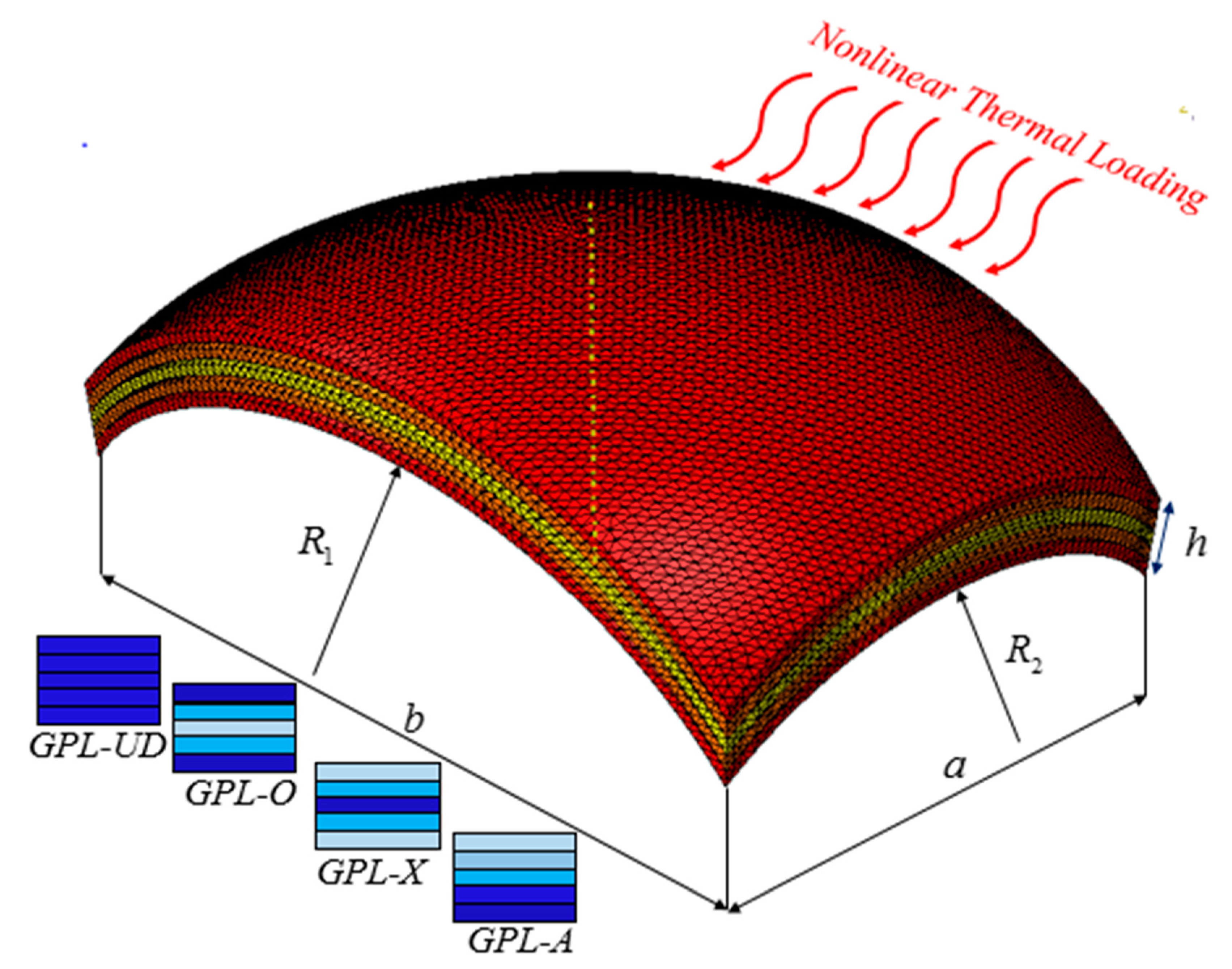
Figure 1. Schematic of a graphene nanoplates-reinforced composite (GPLRC) cylindrical panel subjected to thermal loading.
Applsci 10 03251 g001
Figure 2. Mesh convergency for the finite element (FE) panel model.
Applsci 10 03251 g002
Figure 3. The influences of a/h and μ / h on the frequency for the SSSS boundary conditions with a/b = 5,   l   =   h / 5 , Δ T =   100   K , NL = 10, g G P L = 0.5% and GPL-x.
Applsci 10 03251 g003
Figure 4. The influences of a/h and μ/h on the frequency for the CCCC boundary conditions with a/b = 5, l = h/5, ∆T = 100K, NL = 10, g_GPL = 0.5%, and GPL-x.
Applsci 10 03251 g004
Figure 5. The effects of a/h and μ/h on the frequency for the CSFS boundary conditions with a/b = 5, l = h/5, ∆T = 100K, NL = 10, g_GPL = 0.5%, and GPL-x.
Applsci 10 03251 g005
Figure 6. The influences of a/h and μ/h on the frequency for the CFFF boundary conditions with a/b = 5, l = h/5, ∆T = 100K, NL = 10, g_GPL = 0.5%, and GPL-x.
Applsci 10 03251 g006
Figure 7. The effects of R1/a and GPLRC’s pattern on the frequency for the SSSS boundary conditions (a/b = 5, h = b/10, R2 = 5a, Δ T   =   100 K , g G P L = 0.5%, NL = 10, μ   =   h / 10 ,   l   =   h / 5 ).
Applsci 10 03251 g007
Figure 8. The effects of R1/a and GPLRC’s pattern on the frequency for the CFSF boundary conditions (a/b = 5, h = b/10, R2 = 5a, Δ T   =   100 K , g G P L = 0.5%, NL = 10, μ   =   h / 10 ,   l   =   h / 5 ).
Applsci 10 03251 g008
Figure 9. The effects of R1/a and GPLRC’s pattern on the frequency for the CCCC boundary conditions (a/b = 5, h = b/10, R2 = 5a, Δ T   =   100 K , g G P L = 0.5%, NL = 10, μ   =   h / 10 ,   l   =   h / 5 ).
Applsci 10 03251 g009
Figure 10. The effects of g G P L and R 1 / a on the critical temperature of the GPLRC panel for the SSSS boundary conditions (b/a = 4, h = a/10, R2 = 5b, NL = 10, μ   =   h / 10 ,   l   =   h / 5 , and GPL-O).
Applsci 10 03251 g010
Figure 11. The effects of g_GPL and R_1/a on the critical temperature of a GPLRC panel for the CSSS boundary conditions (b/a = 4, h = a/10, NL = 10, R2 = 5b, μ = h/10, l = h/5, and GPL-O).
Applsci 10 03251 g011
Figure 12. The effects of g_GPL and R_1/a on the critical temperature of a GPLRC panel for the CCCC boundary conditions (b/a = 4, h = a/10, NL = 10, R2 = 5b, μ = h/10, l = h/5, and GPL-O).
Applsci 10 03251 g012
Figure 13. The effects of l/h and R 1 / a parameters on the critical temperature of the GPLRC panel subjected to SSSS boundary conditions (b/a = 4, h = a/10, R2 = 5b, NL = 10, μ   =   h / 10 , g G P L = 1%, and GPL-O).
Applsci 10 03251 g013
Figure 14. The effects of l/h and R 1 / a parameters on the critical temperature of the GPLRC panel subjected to CSSS boundary conditions (b/a = 4, h = a/10, R2 = 5b, NL = 10, μ   =   h / 10 , g G P L = 1%, and GPL-O).
Applsci 10 03251 g014
Figure 15. The effects of l/h and R 1 / a parameters on the critical temperature of the GPLRC panel subjected to CCCC boundary conditions (b/a = 4, h = a/10, R2 = 5b, NL = 10, μ   =   h / 10 , g G P L = 1%, and GPL-O).
Applsci 10 03251 g015
Table 1. The dimensionless natural frequency of the GPLRC panel for different types of boundary conditions, numbers of grid points and patterns when a/b = 6.5, h = a/9, R1 = R2 = 10a, Δ T = 10 (K), and g G P L   = 0.5%.
N = M=7N = M = 9N = M = 11N = M = 13N = M = 15
CFFFPure epoxy0.01528390.01713110.01227860.01843080.0185104
Pattern 20.03204570.03339900.03792720.03401400.0340840
CSFSPure epoxy0.02451070.02791840.02052090.02052090.0205209
Pattern 20.04117260.04108660.04074440.04074440.0407444
SSSSPure epoxy0.03280410.03280390.03280390.03280390.0328039
Pattern 20.06856720.068503820.068443280.068391870.0683808
CSSSPure epoxy0.05511240.055537470.053668110.055523840.0555205
Pattern 20.09713780.09894220.099170050.099295410.0992978
CCCCPure epoxy0.07631700.07635550.07635670.07635670.0763567
Pattern 20.13885390.138898320.138899780.13890350.1389035
Table 2. The dimensionless critical temperature of the GPLRC panel for various boundary conditions, numbers of grid points and length scale parameters when a/b = 0.5, h = a/7, GPL-UD, R1 = R2 = a, g G P L   = 0.3%.
N = M = 7N = M = 9N = M = 11N = M = 13N = M = 15
SSSS l /h = 01.4499191.4491021.4491121.4491111.449111
l /h = 0.41.4634931.4627061.4627141.4627141.462714
CSSS l /h = 02.4664642.4706832.4706222.4706492.470649
l /h = 0.42.5128172.5146892.5148252.5148842.514884
CCCC l /h = 04.2927274.2884844.2883392.2883392.288339
l /h = 0.44.4682424.4311114.4352744.4348094.434809
Table 3. Comparison of dimensionless fundamental frequencies of the GPLRC curved panel (a/b = 1, a/h = 10, R1 = R2 = ).
Resource(n, m)Pure EpoxyPattern 1Patter 2Patter 3
Present(1,1)0.05860.12210.09790.1417
Wang et al. [105] (1,1)0.05840.12160.10230.1365
Song et al. [69](1,1)0.05840.12160.10200.1378
ANSYS [106](1,1)0.05630.11710.08810.1319
Present(1,2)0.14050.29240.23690.3358
Wang et al. [105] (1,2)0.13910.28950.24690.3183
Song et al. [69](1,2)0.13910.28950.24560.3248
ANSYS [106](1,2)0.13610.28330.21620.4043
Table 4. Comparison of dimensionless frequencies ( ω h 2 ρ ( 1 + υ ) / E ) of the isotropic flat curved panel. (a = 10, E = 30 × 106, υ   = 0.3, ρ = 1 , l = 0 and R1 = R1 =   ).
μ / h a/h = 10a/h = 20
b/a = 1b/a = 2b/a = 1b/a = 2
0Ref. [93]0.09330.05900.02390.01500
Presented study0.09270.05830.02340.01496
1Ref. [93]0.08520.05570.0218--------
Presented study0.08490.05450.02130.01474
Table 5. Validation of numerical results with finite element outcomes (b/a = 5, h = a/10, R1 = 6a, R2 = 2a, Δ T = 20 K , g G P L = 1%, and NL = 5).
H = a/15
Numerical Results forFEM Results for Pattern 4Numerical Results forFEM Results for Pattern 3Numerical Results forFEM Results for Pattern 2Numerical Results forFEM Results for Pattern 1
Pattern 4Pattern 3Pattern 2Pattern 1
CCCC7.35 × 1057.28 × 1057.84 × 1057.76 × 1057.12 × 1057.00 × 1057.49 × 1057.41 × 105
CSSS5.28 × 1055.21 × 1055.71 × 1055.63 × 1055.15 × 1055.07 × 1055.43 × 1055.33 × 105
H = a/10
Numerical results forFEM results for Pattern 4Numerical results forFEM results for Pattern 3Numerical results forFEM results for Pattern 2Numerical results forFEM results for Pattern 1
Pattern 4Pattern 3Pattern 2Pattern 1
CCCC7.46 × 1057.39 × 1058.01 × 1057.92 × 1057.31 × 1057.23 × 1057.59 × 1057.52 × 105
CSSS5.43 × 1055.38 × 1055.98 × 1055.90 × 1055.26 × 1055.20 × 1055.65 × 1055.60 × 105
Table 6. Material properties of the GPL [110].
Material Properties:GPL
Young’s modulus (GPa)1010
Density (kg m−3)1062.5
Poisson’s ratio0.186
Thermal expansion coefficient (10−6/K)5