1. Introduction
According to World Health Organization (WHO) statistics, up to one billion people in the world constituting about 15% of the total population live with certain form of disability, including approximately 200 million experiencing considerable difficulties in functioning that limit their participation in family and society life, with the domination of cases in the upper age group of ≥60 years old, where nearly every second a person experiences moderate and about 10% severe disabilities [
1]. Severe disabilities are often associated with lower limb amputations, with approximately 30,000 to 40,000 amputations performed each year, and more than 1.5 million people living with a lost limb in the U.S. alone, with the majority requiring access to lower limb prosthetics [
2]. The total number of lower limb prostheses provided annually in Russia increased from around 60,000 in 2012–2014 to above 80,000 in 2016–2018 [
3].
Although reasons for amputation vary considerably between regions and age groups, ranging from severe trauma, wounds and burns caused by road traffic and occupational injuries as well as violence and humanitarian crises to tumors and inflammatory diseases potentially leading to the development of sepsis and multiple organ failure, on average around one half of amputation cases can be attributed to either trauma or disease, respectively [
1,
4].
Modern prosthetics largely rely upon technological support to improve the accuracy of design and finally to enhance the quality of rehabilitation taking into account the individual characteristics of the patient. Current technologies allow for a highly automated prosthetic design procedures based on the geometry and properties of human organs obtained by 3D scanning [
5] or computed tomography (CT) scanning [
6] followed by prosthetic model reconstruction. In addition to the design itself, adequate 3D models allow for running biomechanical simulations, leading to certain optimization strategies based on objective visual data sources and numerical mathematics [
7]. In some cases, appropriate model design requires a combination of different technologies. In contrast to 3D scanning, CT and magnetic resonance imaging (MRI) are also capable of visualization of soft tissues [
8,
9]. Thus, modern scanners with the usage of digital models and mathematical simulations can predict the behavior of patient’s organs at both micro [
10] and macro scales [
11] as well as over different time spans [
12].
Modern approach to the design of receiving sockets for lower limb prostheses typically consists of the following stages:
- 1.
3D scanning of the lower limb stump;
- 2.
Design and analysis of a digital geometric model;
- 3.
Printing the prosthetic socket using a 3D printer.
The 3D scanning involves recording of the surface points coordinates [
13] using a 3D scanner or recording device followed by the reconstruction procedure used to obtain a 3D-model of a limb segment. One of the key stages in 3D-model processing is the orientation of the model in 3D Cartesian coordinates.
Among recent approaches to the automation of the 3D-model orientation problem, using various mathematical filters for reconstructions of the 3D-model from 2D X-ray images can be mentioned [
14]. The rotation matrix used for the automatic orientation of the model is in 3D space. However, this approach is limited to certain specific 3D-model rotation angles.
Another approach is based on the virtual environment that is used to automatically select the position of the 3D-model in three-dimensional space is considered in [
15]. The key disadvantage of this particular method is that it limits possible 3D-model orientations to a set of specified templates.
In another recent work [
16] orientation of the 3D image of the scapula is based on the preliminarily fixed markers that are being further compared against the control model. The disadvantage of this method is that the expert needs to place markers in the 3D-model manually.
A commonly applied solution is a web-based program, Rapid Plaster (PVA Med, New York, NY, USA), developed for the design of prosthetic sockets allowing users to work with a 3D-model in a conventional browser and convert it using standard tools for working with 3D models, although again it lacks a component that could be used for the automated orientation in 3D space [
17].
Current classification of socket types, their common advantages and limitations from multiple viewpoints, as well as an overview of the keynote parameters affecting the stump–socket interface and influencing the comfort and stability of the limb prostheses such as displacement, stress, volume and temperature fluctuations for different positioning and orientation scenarios are reviewed in [
18].
A physically motivated reduced model of the dynamic interactions between the residual limb and the prosthetic socket proposed in [
19] is capable of the quantitative assessment and simulation of the stress distribution for different variants of the socket orientation and positioning as well as its possible alterations depending on the corresponding variation in the friction coefficients.
Another recent knowledge-based approach to the design and orientation of the lower limb prostheses with particular focus on the 3D modeling of the socket is based on the acquisition and formalization of the knowledge related to the prosthesis manufacturing process as well as the architecture of a dedicated knowledge-based engineering framework detailing the key design steps. A computer-aided module named socket modeling assistant (SMA) represents a virtual laboratory where the socket prototype is being created and positioned based on the digital model of a patient’s residual limb. The SMA software acts as an interactive tool to guide and support the expert socket designer during each step from socket design to its positioning and orientation either in an automatic or in a semi-automatic fashion [
20].
The authors of [
21] focus on untangling the complexity of the transtibial prosthetic socket fit by selecting the keynote characteristics that guarantee its successful fitting as well as finding certain criteria for the optimized selection of the particular prosthetic socket type for different positioning and orientation scenarios. Based on the analysis of the activity levels and reported satisfaction of active persons, especially among younger persons mainly with a traumatic cause of amputation, they conclude that the total surface-bearing sockets generally outperform the patellar tendon-bearing sockets, as they can be better adjusted to the lower limb stump in order to withstand dynamic loads typically associated physical activity.
Socket biomechanics, socket pressure measurement, friction-related phenomena and associated properties, with corresponding computational models describing the limb tissue responses to the external mechanical loads and other physical conditions for different socket positioning and orientation scenarios are the key focus of [
22]. Further advancement of this research is associated with the embedded sensors enabling direct measurements of the physical stresses applied to the socket [
23]. The results of this study indicate that the direction and the angle of rotation of the stump could be obtained by decoding the magnetic field signals obtained by magnetic sensors embedded into a prosthetic socket. This pilot study provides important guidelines for the development of a practical interface between the residual bone rotation and the prosthesis for control of prosthetic rotation.
The conventional approach to the prosthetic socket orientation includes splitting the stump 3D-model into sections according to a discrete grid in the horizontal plane followed by obtaining the resulting dimensions from the cross-section perimeters. Accordingly, registration of the cross-section perimeters while the 3D model is positioned at the wrong angle to the horizontal plane leads to incorrect measurements. Thus, it is essential to create an algorithm that provides at least preliminary automated orientation of the 3D-model based on objective measurement data. Due to high variability in the stump characteristics and the individual shape of each stump, especially in each congenital malformation case, in certain scenarios only preliminary conclusions can be made automatically, and expert attention will, nevertheless, be required. However, even in this scenario, an automatic decision support system (DSS) could save an expert’s time and provide at least preliminary positioning.
In this work, we propose an automated orientation algorithm based on the adjustment of the 3D-model virtual anatomical axis of the tibia along with the vertical axis of the rectangular coordinates in three-dimensional space. The suggested algorithm is implemented, tested for performance and experimentally validated by explicit comparisons against an expert assessment. We believe that the proposed solution could be useful as a DSS for the prosthetic expert support.
The automated system development is based on the algorithm of orientation of the digital geometric model of the lower limb stump in an automatic mode, and consists of the following steps:
- 1.
Design of the 3D-model of the lower limb stump obtained by 3D scanning of the patient.
- 2.
Development of a decision support system for the automatic 3D-model orientation.
- 3.
Comparative analysis of the model-based predictions with expert evaluation results.
- 4.
Estimation of the algorithm performance including the duration of automatic orientation for a given resolution setting associated with the number of 3D-model polygons.
2. Materials and Methods
The anonymous experimental data for the study were obtained from the Federal Scientific Center of Rehabilitation of the Disabled named after G.A. Albrecht. The study was performed in accordance with the ethical standards presented in the Declaration of Helsinki. The study protocol was reviewed and approved by the local expert collegiate council before the beginning of the study. All patients provided their written informed consent prior to their inclusion in the study.
The study focused on the patients with unilateral, bilateral and multiple amputation defects with various causes of amputation defects, with one lower limb having one defect at the lower leg level. The following patients were excluded from enrollment in the study: those with skin defects such as non-healing wounds; those with trophic ulcers; those exhibiting tremor of the extremities due to various diseases; those with protrusion of bone sawdust under the skin that prevents prosthetics; those suffering from either acute myocardial infarction or acute cerebrovascular accident within 4 months prior to the study; those exhibiting mental illness in the acute stage; those with contagious infectious diseases; and those with complication of the main and/or concomitant disease with the appointment of bed rest.
Among seven patients selected for detailed investigation, four were male and three female, aged between 45 and 58 years old.
Mathematical analysis and functional programming tools (Python 3.3.7 with Mesh library,
www.python.org) were used for visual data processing, model design and computer simulations. The loop optimization method was used to select the points with maximum displacement [
24]. Multidimensional regression method was used for 3D-model cross-section fitting [
25]. For 3D-model orientation, quaternions [
26] and rotation matrices have been used [
27].
The developed algorithm (see Algorithm 1) performs an automatic orientation of the 3D-model. The key steps of the algorithm are as follows:
| Algorithm 1 |
- 1.
Data import (e.g., reading from file) - 2.
Selection of points with maximum coordinates (loop optimization method) - 3.
Primary 3D-model spatial orientation - 4.
Setting cross-section under control by the operator - 5.
Arrangement of the points defining the cross-section - 6.
Finding cross-section central points - 7.
Calculation of the virtual anatomical axis - 8.
Secondary 3D-model spatial orientation - 9.
Data export (e.g., saving to file)
|
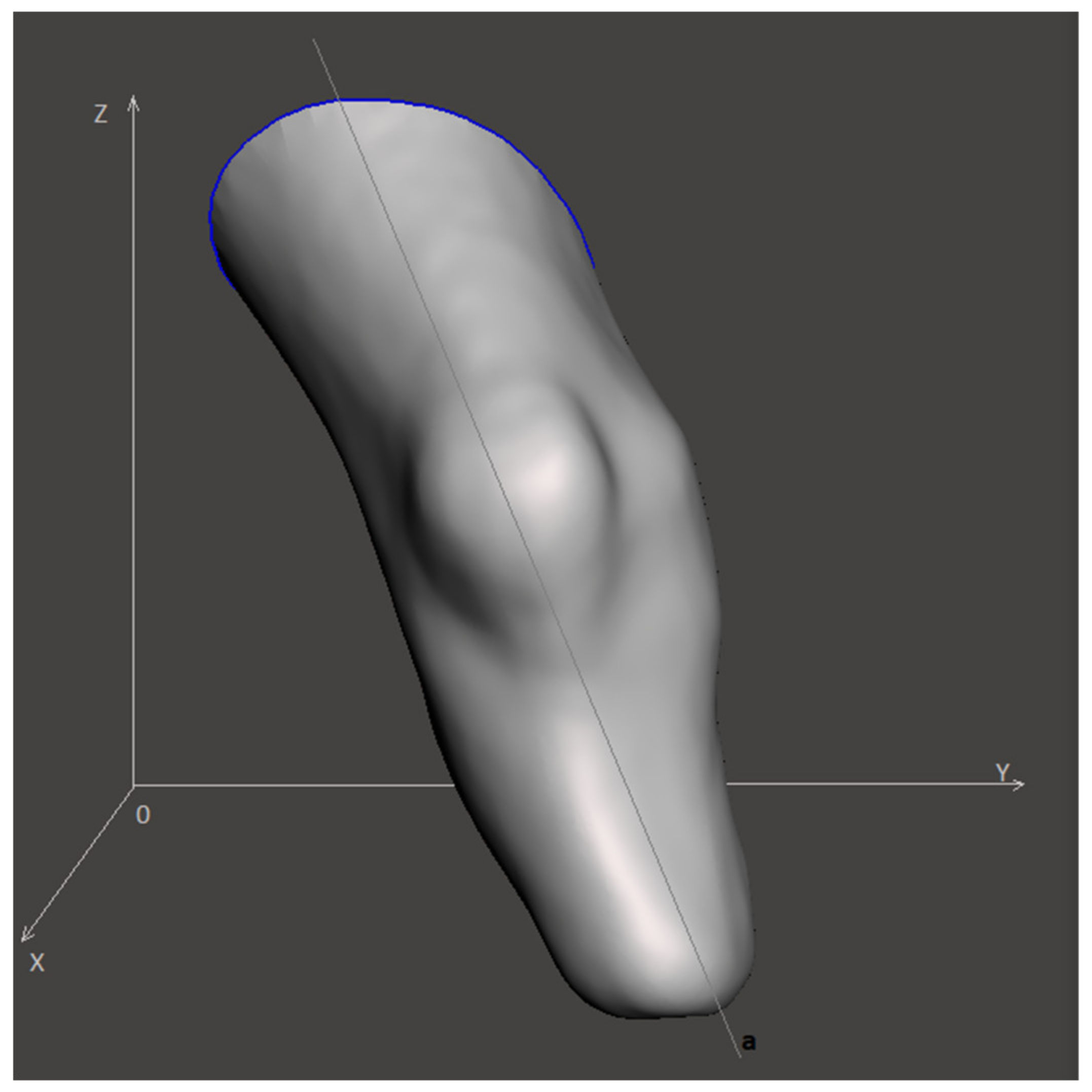
In the first step a digital representation obtained by a 3D scanner is imported as an array of coordinates containing the points
ri = (xi, yi,
zi). Once imported, all entries are sorted according to their coordinates along the Z axis.
Figure 1 illustrates the visual representation of the input model, where x, y, z are Cartesian axes, while a is the virtual anatomical axis. The spatial orientation of the model is determined by the angles between the projections of the anatomical axis a on the xy, xz and zy planes.
Next, the points
ri = (xi,
yi,
zi) characterized by the maximum coordinates (step 2 of the algorithm) have been selected as:
To enable the rotation of the digital 3D model, we employed a set of transformations following the rotation matrices approach. In 3D space rotation around the Z-axis is described by the matrix transformation.
Similarly, rotation around the X-axis has the form:
Rotation around the Y-axis is given by:
Next, the coordinates of the point
ri can be written as a series of consecutive transformations.
The resulting transformation matrix can be interpreted as a matrix of the direction cosines between the old and new coordinate systems.
The described approach has been used both for the primary and for the secondary orientation of the model (steps 3 and 8 of the algorithm).
The normalized vector indicating the direction that connects these points relative to the global coordinate system
rdir can be expressed as:
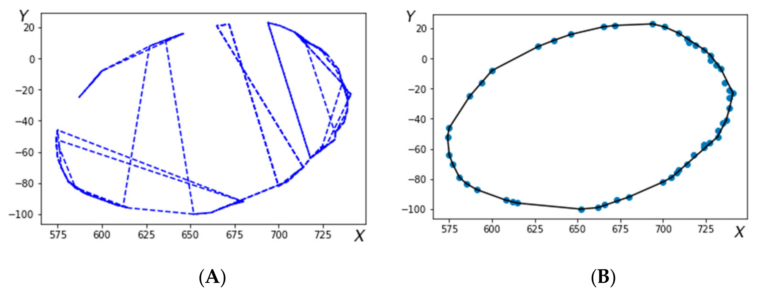
Figure 2 shows the cross-sections of the 3D-model before (2A) and after (2B) arrangement.
Following the arrangement of the points constituting the cross-section a closed contour is selected (step 5 of the algorithm). Creation of a closed contour starts from a reference point and proceedings following the oriented direction obtained at each j-th step from:
Arrangement of this array according to a specific variable D
j, defines an ordered closed set of points, as exemplified in
Figure 2b, where r is an array of coordinates containing the points
ri = (xi,
yi,
zi).At step 6, the central (pivot) points are obtained by averaging the coordinate points for each of the cross sections specified by the operator. Next at step 7 a straight line through the central points (obtained at step 6) is fitted using the multidimensional regression method. In particular, the error ε is being minimized in the model:
where Y contains z-coordinates from the dataset r, Z contains x- and y-coordinates from the dataset r, b and d are free model parameters, while ε is the random error. The problem (10) can be resolved using the least mean squares (LMS) method.
thus yielding.
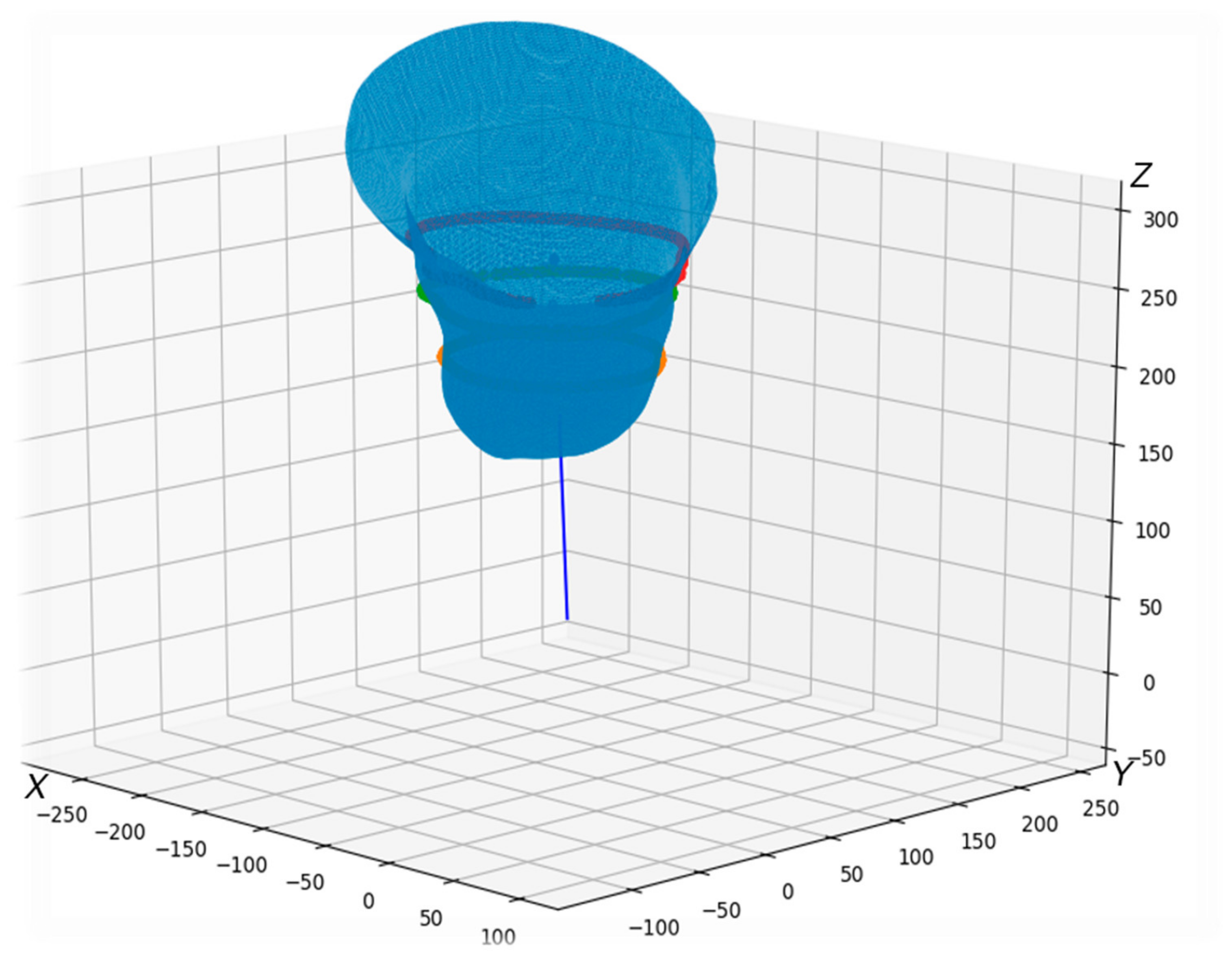
Finally, the cross-section levels of the lower limb stump in the 3D-model are obtained, and the entire 3D-model is aligned along the Z-axis (see
Figure 3) before being exported.
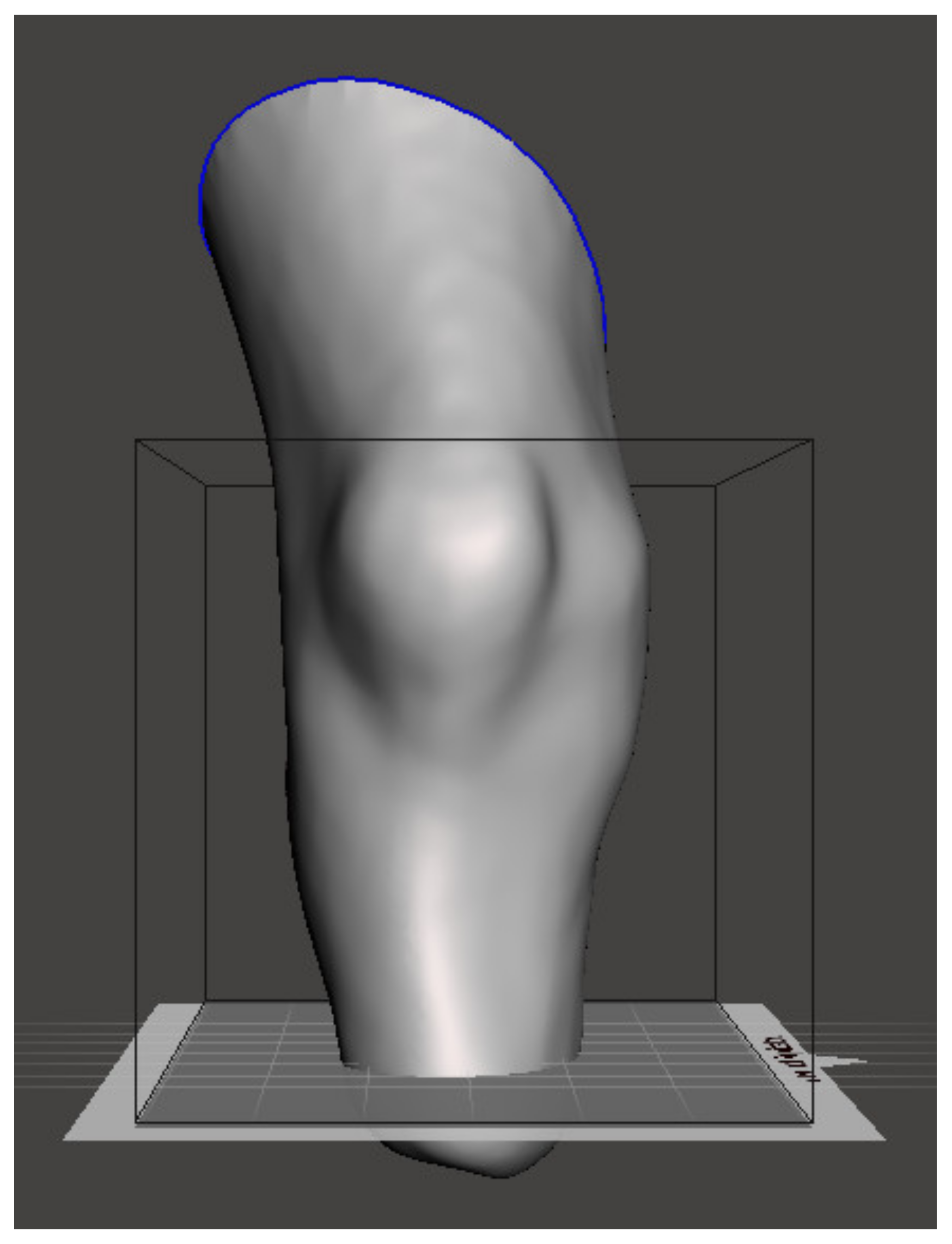
Figure 4 shows the model appearance after the orientation using the designed algorithm.
3. Results
The validation of the proposed algorithm was performed using experimental data obtained by 3D scanning followed by 3D model reconstructions for seven different patient cases as summarized in
Table 1. To validate the tests under different initial conditions, prior to the test each 3D model was randomly oriented. Since there is no “gold standard” for an automated algorithm in the field, the results of the automatic orientation algorithm were compared against manual positioning by an experienced prosthetic expert.
For the quantitative comparison between the automated and the expert manual positioning, two pivot points, one on the distal and one on the proximal planes, were selected, and a straight line connecting these two points was fitted. Once the model orientation was performed independently by the automated algorithm and manually by the expert, the two spatially oriented models were matched by the point in the distal plane. Three projections of the straight line on the xy, xz and zy planes were obtained for both automated and manually oriented models, and angles between these projections in each plane were used for the quantitative comparison between the two approaches, as summarized in
Table 1. In the above procedure, the exact locations of the pivot points are not critical for the accuracy of the comparison, since they are used for measuring relative orientations only.
Although in this work we focused on the lower limb stump orientation problem, the proposed algorithm appears to be a universal tool for the 3D model orientation. We have implemented the algorithm using Python programming language and Mesh library features (the source code is available as
Supplementary Material). The developed software module follows the algorithm represented below in pseudocode (see Algorithm 2). The algorithm contains two key verification conditions, with the first condition checking whether the virtual anatomical axis of the tibia coincides with the vertical Z-axis, while the second condition triggering if the model is positioned with the stump end up after orientation. Since the construction of the cross-sections depends explicitly on the anatomic characteristics of the lower limb stump, it is specified by the operator for each 3D-model in an individual range.
The axis of the model should coincide with the Z-axis, since this orientation is required for a more intuitive manual positioning by the expert, who is more used to traditional technology assuming the adjustment of the stump cast installed vertically. After the manual adjustment is performed, the entire model can be re-positioned and re-oriented as required to match with the actual biomechanical axis.
The angle of the virtual axis along the tibia to the vertical Z-axis is affected by the angle of the 3D-model slice after scanning.
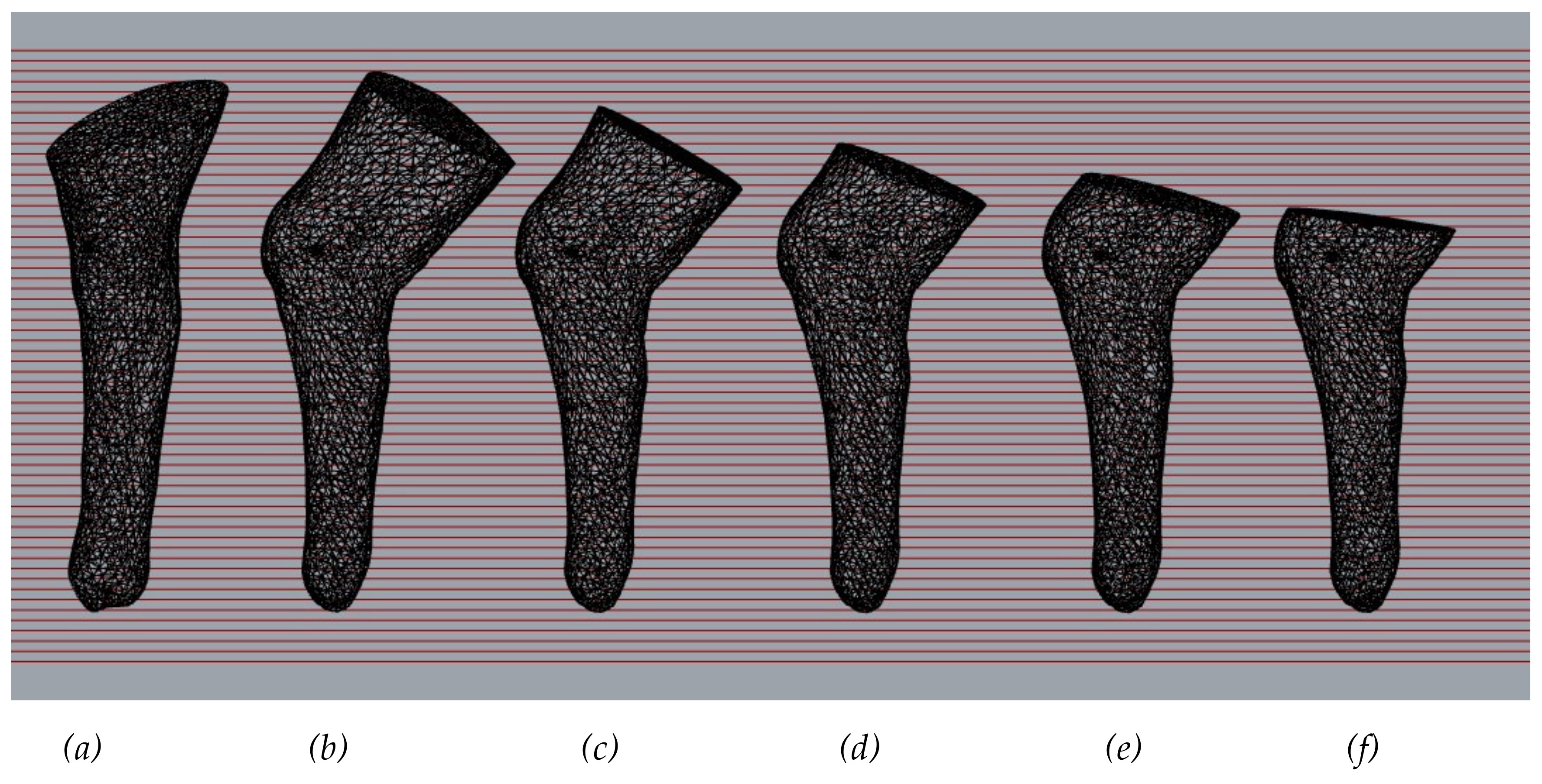
Figure 5 compares the models obtained after orientation, where (
a) is an expert oriented 3D-model, while 3D-models (
b)-(f) are different variant of 3D-model oriented by the proposed algorithm. The 3D-model gradually shortens the end above the knee. The data obtained show the following: the shorter the femoral part of the 3D-model, the smaller the deviation of the virtual anatomical axis of the tibia from the vertical Z-axis.
| Algorithm 2 |
- 1.
Data import (e.g., reading from file): array Data(3, N), where N–number of points. - 2.
Selection of points with maximum coordinates: calculate Rmax, Rmin according to Equations (1) and (2) - 3.
Estimation of the rotation angles: calculate matrix M–array RotMat(3, 3) for direction (Rmin, Rmax) according Equation (8) and recalculate data according to Equation (7) - 4.
Arrangement points in the cross-section: calculate array DataOrd(3, N) according to Equation (9), calculate central points of sections by averaging CentralData(3,K), where K–number of sections - 5.
Fitting a regression line: for CentralData calculate vectors bVec and dVec according to Equation (12) - 6.
Estimation of the rotation angles: calculate RotMat(3, 3) for direction bVec and recalculate Data according to Equation (7) - 7.
If 3D model axis does not coincide with Z axis, then go to line 2 - 8.
Setting cross-section under control by the operator - 9.
3D model centering - 10.
If 3D model inverted, then flip over the model - 11.
Data export (e.g., saving to file)
|
Consequently, the input requirements for the algorithm performance are: (i) 3D-model scan length above the knee and (ii) the angle of inclination of the cross-section plane of the scan above the knee to the anatomical axis of the femur.
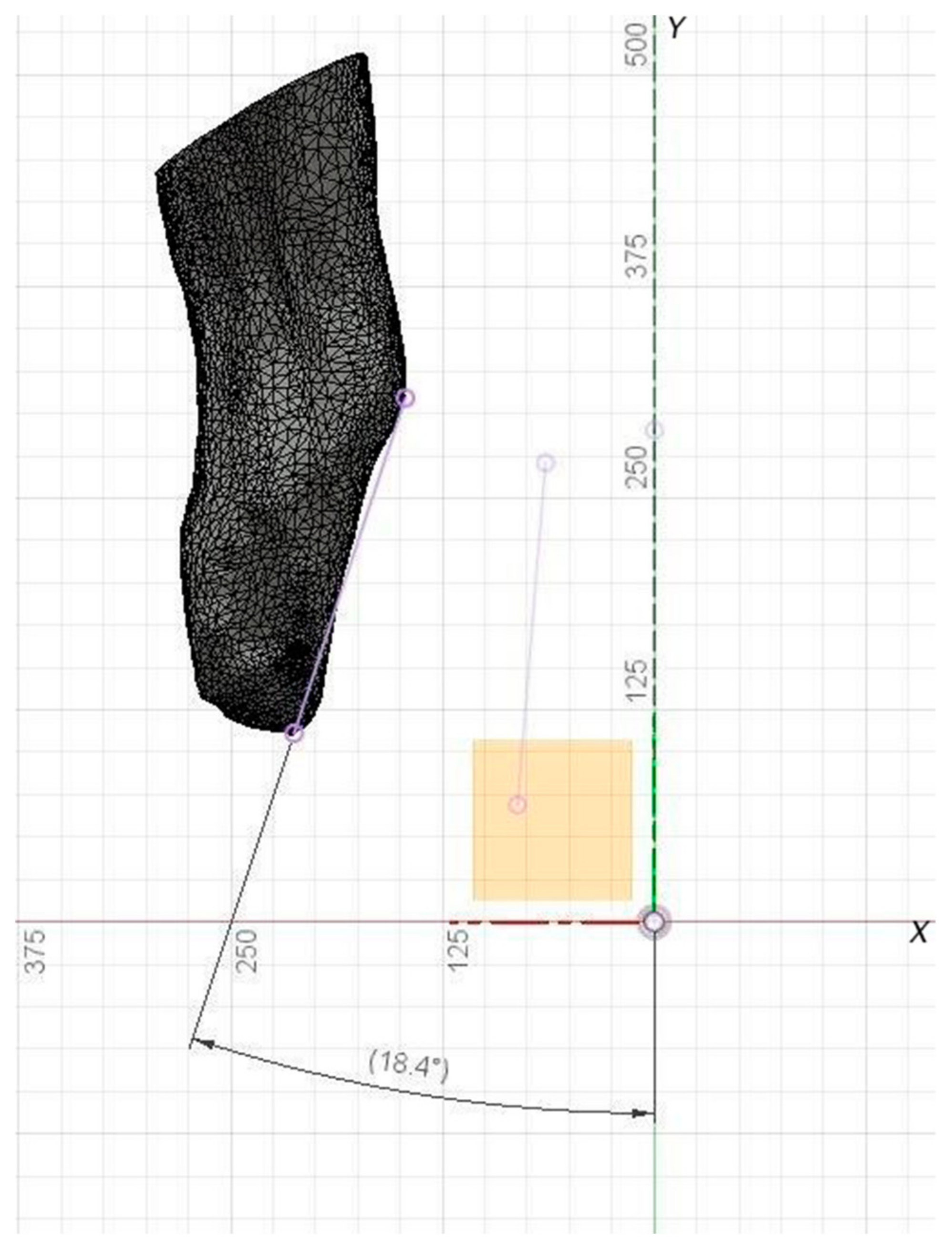
For comparison the inclination angle input models can be marked with reference points. To analyze the angles of deviation of the virtual anatomical axis of the tibia from the Z ax is after orientation by the algorithm and the expert. In
Figure 6, a straight line drawn through reference points allows the results to be compared visually.
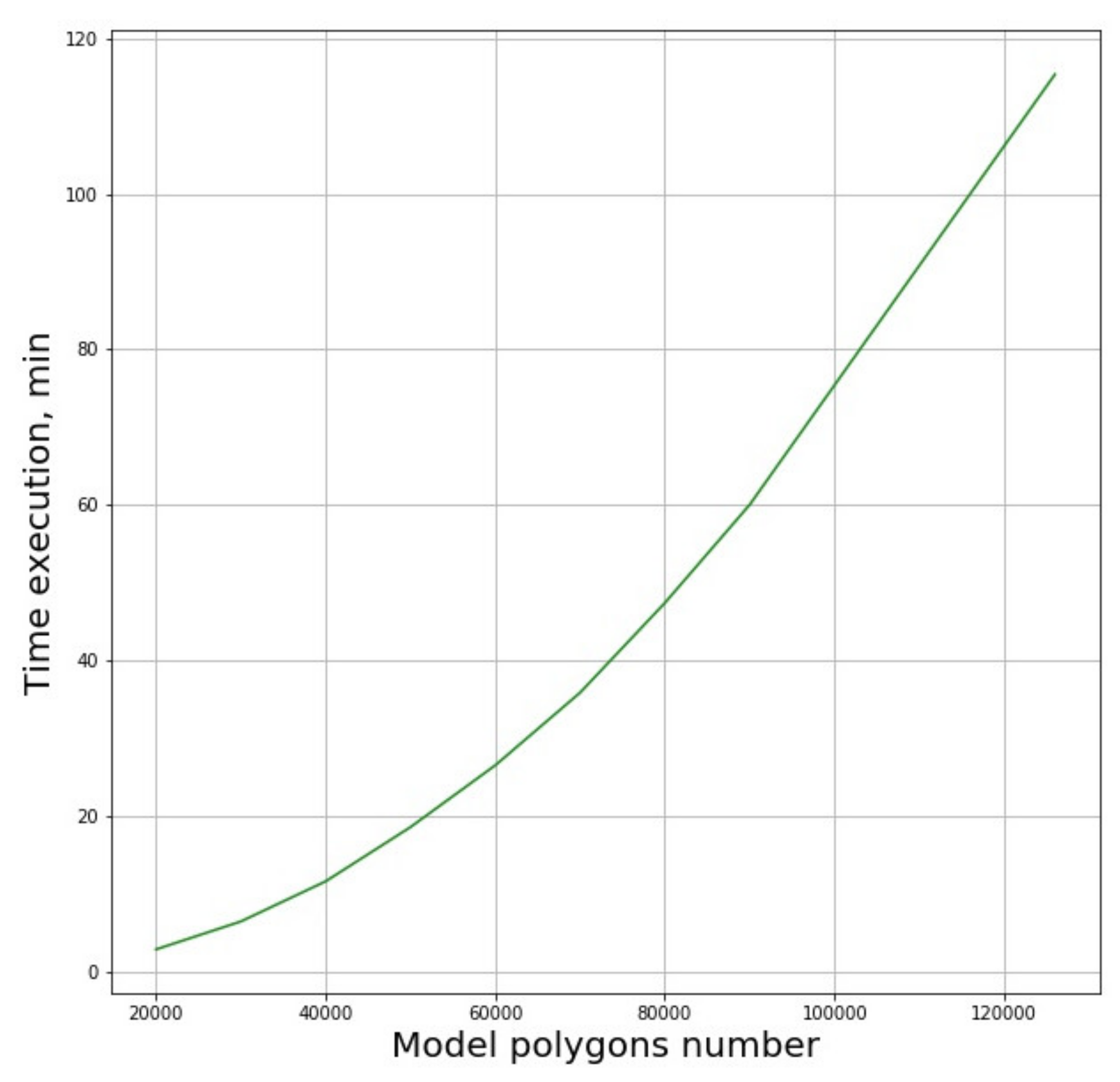
Performance of the algorithms depends explicitly on the number of polygons. The dependence of the analysis time on the number of polygons in the model is shown in
Figure 7.
The presented dependence function can be reasonably fit by a second order polynomial. It was found that significant simplification of the original model leading to the six-fold reduction of the number of polygons from 120,000 to 20,000, the algorithm’s operation time is reduced by approximately 1.5 orders of magnitude. Thus, reduction of calculation time can be achieved by any measures that lead to the reduction of the polygon number, such as smoothing of the 3D-model surfaces.
4. Discussion
Based on the results obtained, it can be assumed that the developed algorithm provides with relatively good agreement with the expert assessment typically within 10 degrees along the vertical axis in any direction, as revealed by comparison of the fitting line obtained by the automatic algorithm and a similar line fitted for the model oriented manually by the expert. The most pronounced deviations could be observed in the third section for the fifth patient that could be attributed to the specific anatomic features of the stump. As indicated in
Table 1, no relevant results were obtained for the second patient, as attempted analysis resulted in the inverted positioning of the 3D model. A possible reason for this result is that the angle of inclination of the 3D-model cross section plane above the knee to the virtual anatomical axis of the femur was untypically sharp, resulting in the input requirements not being fulfilled.
The limitations of the proposed approach include limited automation, as the expert has to define the position of the proximal edge of the stump to determine the location of the upper section. We also have to note that the algorithm in its present implementation relies upon the assumption that the virtual anatomic axis is orthogonal to the sagittal plane, which is not exactly, but only approximately fulfilled especially for longer models, see also
Figure 6 for visual reference.
In our opinion, the above algorithm, taking into account all its inherent limitations, can nevertheless be used as a decision support tool for the prosthetic expert and 3D designer considerably reducing the workload of qualified personnel. Among relevant analogues, the work [
28] should be mentioned, where 2D cross-sections of the upper and lower limbs 3D-model were used to create a “bone structure”. The sections were created by placement of any number of parallel planes inside the 3D-model and calculating corresponding intersections between the 3D-model and the plane. This “bone structure” can be used to determine the orientation of the scanned model in 3D space in order to create additional cross-section images, as well as obtaining basic information about the shape of the hand or foot or missing fingers, which can be used to create a 3D-model of the prosthesis. However, getting accurate dimensional information about the 3D-model being scanned will require additional input data from the user to determine the scale of the 3D-model, which in our opinion appears to be a certain limitation of this approach, as preprocessing of the 3D-model by an expert is required increasing the workload and potentially reducing the objectivity of the first approach to the model orientation.
As an outlook, we believe that further optimization of the algorithm could make the dependence of the performance on the number of polygons in the 3D-model less pronounced. For that, an algorithm module that allows orientation of the 3D-model in a horizontal plane using the quaternion method for rotating an array of 3D-model points sounds a perspective solution. Since recent technological advancement has enabled the estimation and simulation of the distribution of stresses applied to the residual limb tissues, as well as the volume fluctuations affecting the stump over time and the temperature variations influencing the residual tissues for different variants of socket design, a more automated functional socket design may be developed in the near future. Moreover, recent advancements in prosthetic technologies suggest that future directions could be associated with advanced socket designs capable of self-adaptation to the complex interplay of factors affecting the stump, under both static and dynamic loads, as a replacement for the current fixed socket-orientation scenario [
18].

 ,
, 


