1. Introduction
The abrasiveness of rocks significantly influences the wear endured by excavation tools in tunnel boring machines (TBMs). Particularly in slurry shield TBMs, wear occurs not only in the excavation tools but also in the discharge pipes and pumps of slurry transport systems. A planned or unplanned cutterhead intervention is necessary for assessing the condition of the cutterhead in TBMs, and in order to replace or repair worn or broken excavation tools. Furthermore, the regular maintenance of slurry pipes, including processes such as pipe thickness measurement, rotation, and replacement, is required to prolong the life cycle of slurry pipes. The consumption of disc cutters, slurry pipes, and pumps has a significant impact on the maintenance of TBMs and on overall construction costs and time in general.
Wear involves the gradual removal of material from a solid surface via abrasion, corrosion, or a combination of both. Abrasive wear is the most common type of wear that occurs in disc cutters, where a harder material abrades a softer material. Erosive wear typically occurs in slurry transport systems, where the material is slowly eroded from a surface owing to the effect of small particles on the surface.
Wear prediction models for disc cutters are based on cutter ring wear due to the abrasiveness of rocks. The interaction between the disc cutter rings and the surrounding rock during excavation involves a complex tribology system. The Colorado School of Mines (CSM) [
1], Norwegian University of Science and Technology (NTNU) [
2], and Gehring models [
3] are the most common models used to estimate cutter wear.
The CSM model is based on disc cutter life, defined using the Cerchar Abrasivity Index (
CAI) [
4]. The
CAI is the most popularly used method for describing the abrasiveness of rocks. The rock specimen is firmly placed in a clamp, and a steel pin with a Rockwell hardness scale C (HRC) of 55 is mounted on the rock surface under a static force of 70 N. The rock surface is slowly scratched to a length of 10 mm. This method is repeated at least five times in directions parallel and perpendicular to the original scratching direction on the rock surface using a new or resharpened steel pin tip each time. The
CAI is then determined by measuring the diameter of the worn flat pin at an accuracy of 0.01 mm, and calculated by multiplying this diameter in units of 0.01 mm by 10.
The Cutter Life Index (
CLI) is considered regarding the NTNU model to evaluate the disc cutter life through various special tests proposed by NTNU. The
CLI is evaluated using Siever’s J-value (
SJ) and abrasion value steel (
AVS).
SJ represents the rock surface hardness and is calculated as the average of a drill hole depth in 1/10 mm following 200 turns of an 8.5 mm drill bit.
AVS is the weight loss measured in milligrams of a test part of steel from a new cutter ring after 1 min, i.e., 20 revolutions. The
CLI can be expressed using
SJ and
AVS, as follows [
5]:
The Gehring model exploits the relationship between the
CAI and the weight loss due to wear of a disc cutter. The specific wear on a disc cutter, in mg steel per meter rolled, is expressed as follows [
3]:
where
vs is the specific disc cutter wear in mg/m.
The wear of cutting tools, including disc cutters, can be measured using the wear coefficient. The wear coefficient (
wc) is defined as the ratio of the radial abrasion of the disc cutter ring (
a), in mm, to the travelled distance of the disc cutter ring (
r), in km, as follows:
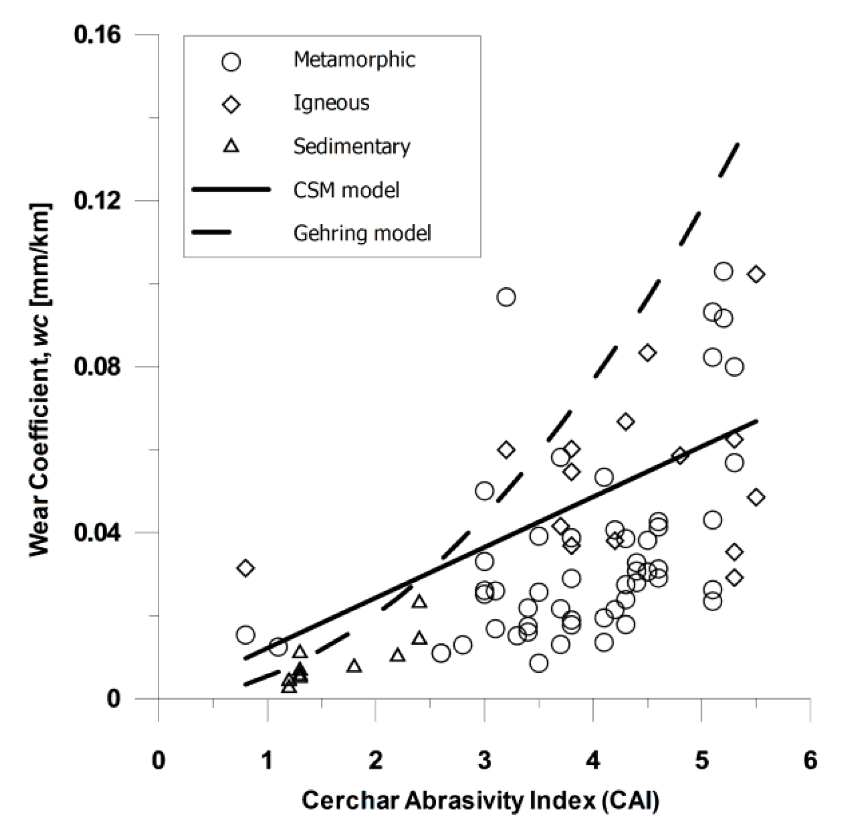
A higher wear coefficient indicates a faster decrease in the disc cutter lifespan, and the wear coefficient is closely associated with rock abrasiveness. Few studies have investigated the wear coefficients of disc cutters. Frenzel [
6] showed the relationship between the wear coefficients of 17 inch disc cutters and
CAI, as illustrated in
Figure 1.
The relationships between geological parameters and cutter life were determined by Hassanpour et al. [
7]. Their findings indicate that intact rock properties, including Vickers hardness number of the rocks (VHNR) and uniaxial compressive strength (UCS), exhibited the highest level of correlation with cutter life. Macias et al. [
8] introduced a rolling indentation abrasion test (RIAT) for rock abrasiveness. RIAT is designed to replicate actual wear behaviour more accurately than other more commonly used methods can, in the context of boring hard rock tunnels. Geng et al. [
9] investigated the effect of the cutterhead design of TBM face cutters on cutter consumption based on the data from six projects. Su et al. [
10] developed a wear model for analysing disc cutters based on the wear mechanism and motion analysis of the cutter rings. They found that the cumulative wear depth and advance distance are correlated linearly. As tunnelling progresses, the wear rate varies, owing to variations in geotechnical or operating parameters.
Several studies have been conducted on slurry pipe wear in relation to mining, dredging, paper and pulp, sewage pumping, and agricultural waste industries [
11], but few have been conducted on slurry shield TBMs. The wear of slurry discharge pipes can be evaluated based on the wear rate. The wear rate (
wr) is defined as the ratio of the degree of pipe wear, in mm (
p), over a given period to the advance distance of TBM, in m (
d), and it is expressed as follows:
The wear rate is proportional to the flow velocity, volume, size, and shape of the material used in the slurry. A power-law relationship describing the slurry flow velocity is one of the most commonly used expressions, as follows [
12]:
where
V is the slurry flow velocity, and
n is the power index based on the material and other variables, and its value ranges between 1 and 4 for slurry pipes.
Karabelas [
13] proposed that the annual wear rate (mm/year) is related to the slurry particle diameter and slurry transport speed, as follows:
where
d is the slurry particle diameter, in mm, and
V is the slurry transport speed, in m/s.
In this study, the effect of rock abrasiveness on the wear of disc cutters and slurry discharge pipes was examined. The radial wear of disc cutters and the thickness of slurry discharge pipes were measured at a slurry shield TBM site in Singapore. The wear of the disc cutters was assessed considering the wear coefficient of a 19 inch disc cutter. The relationships between the weathering grade of Bukit Timah granite and the wear coefficient of disc cutter rings were investigated, and the correlation between CAI and wear coefficient of disc cutters was determined.
In addition, the average wear rates of slurry discharge pipes for Bukit Timah granite were estimated through pipe thickness measurements. Based on the weathering grade of the Bukit Timah granite, the relationship between the wear coefficients of the disc cutters and the wear rates of slurry discharge pipes was investigated.
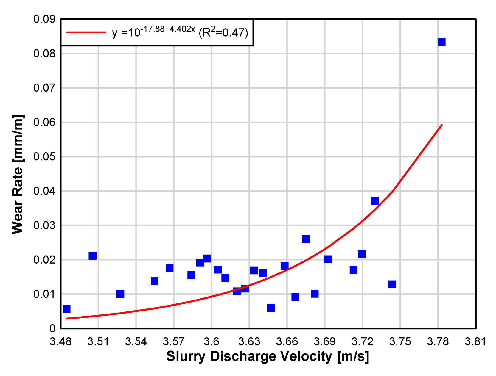
Finally, the relationship between the slurry discharge velocity and the wear rate was derived.
2. Materials and Methods
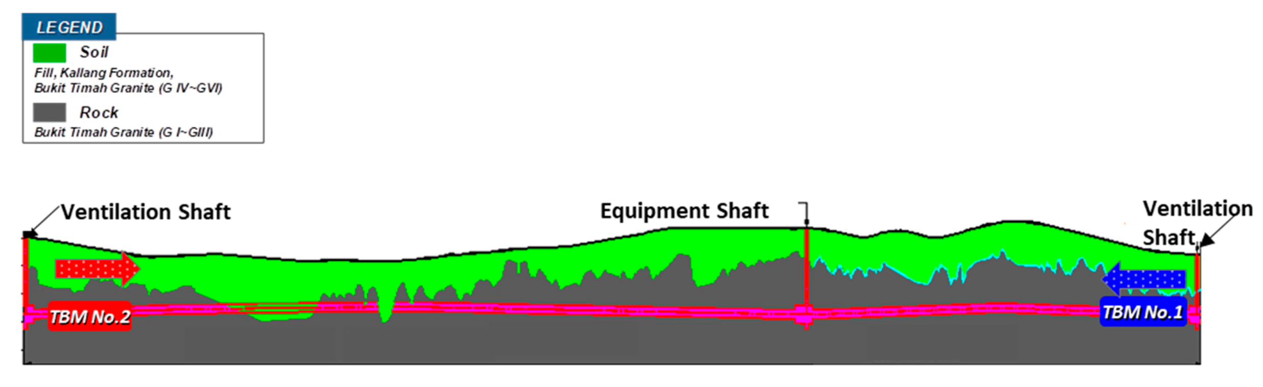
Figure 2 illustrates the geological conditions along the tunnel route, wherein Bukit Timah granite from fresh weathering grade G(I) to residual soil G(VI), a mixed face of soil and rock, and alluvial deposits of the Kallang formation exist. The Bukit Timah granite was generally composed of granitic rocks and various minority lithologies, including dolerite, diorite, basalt, dacite, and rhyolite. The depth of the tunnel alignment varied from 32.5 to 65 m. The tunnel centreline level was up to 62 to 65 m below ground level. The water table along the tunnel route was generally less than 5 m below ground level, indicating that the water pressure at tunnel level was very high, typically above 4 bar and exceeding 6 bar along some alignment sections.
Table 1 lists a summary of the geomechanical characteristics of the Bukit Timah granite located at the project site. The weathering classification of the Bukit Timah granite, in accordance with BS 5930 [
14], is shown in
Table 2.
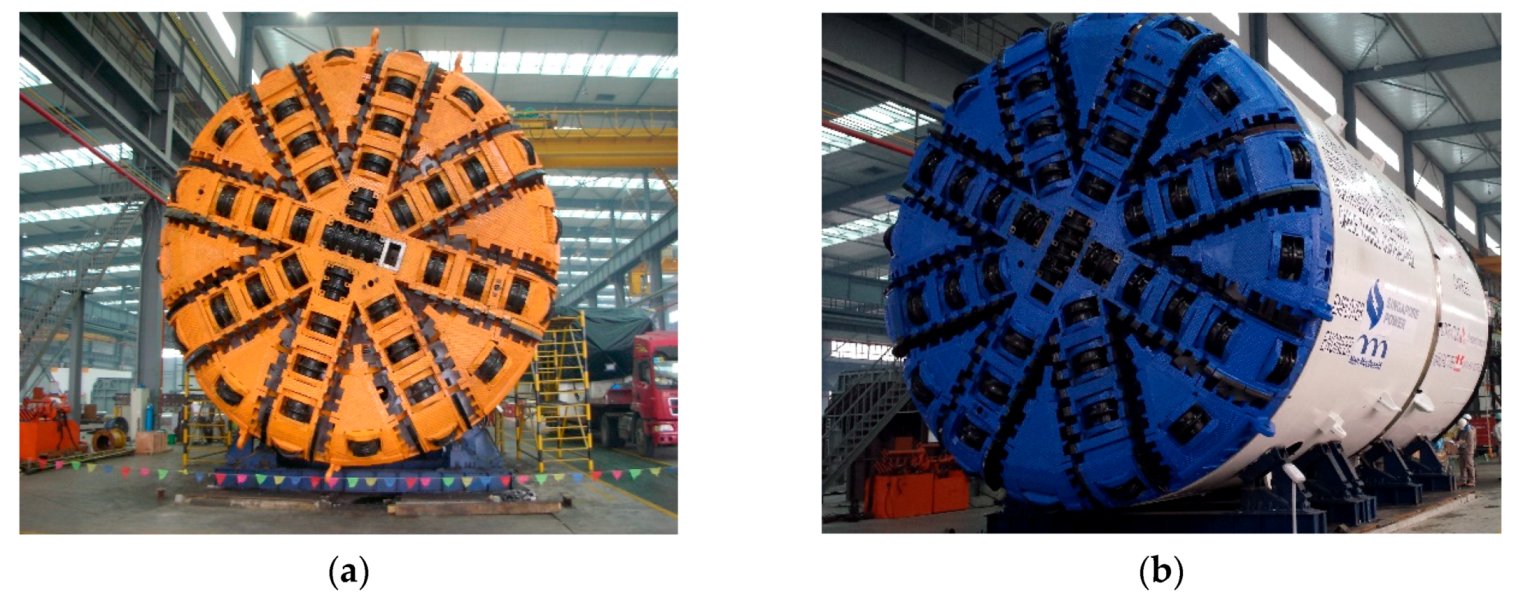
A 5.29 km long, single-tube tunnel was excavated using two slurry shield TBMs 6.9 m in diameter. A slurry shield TBM can be used to control and prevent the inflow of groundwater through the excavation face when appropriate pressure is applied. The slurry shield TBM was equipped with a 19 inch disc cutter, and equipped with a total of 48 cutter rings and a cutter spacing of 85 mm.
Table 3 lists the TBM specifications, and
Figure 3 shows photographs of the TBMs used for the project. The degree of disc cutter wear was measured during the cutterhead intervention. A total of 126 cutterhead interventions were conducted for TBM No. 1, which was used to excavate 2.64 km. For TBM No. 2, which was used to excavate 2.65 km, 125 cutterhead interventions were carried out.
Figure 4 shows the measurement of disc cutter wear during the cutterhead interventions. The degree of wear was measured using a special ruler.
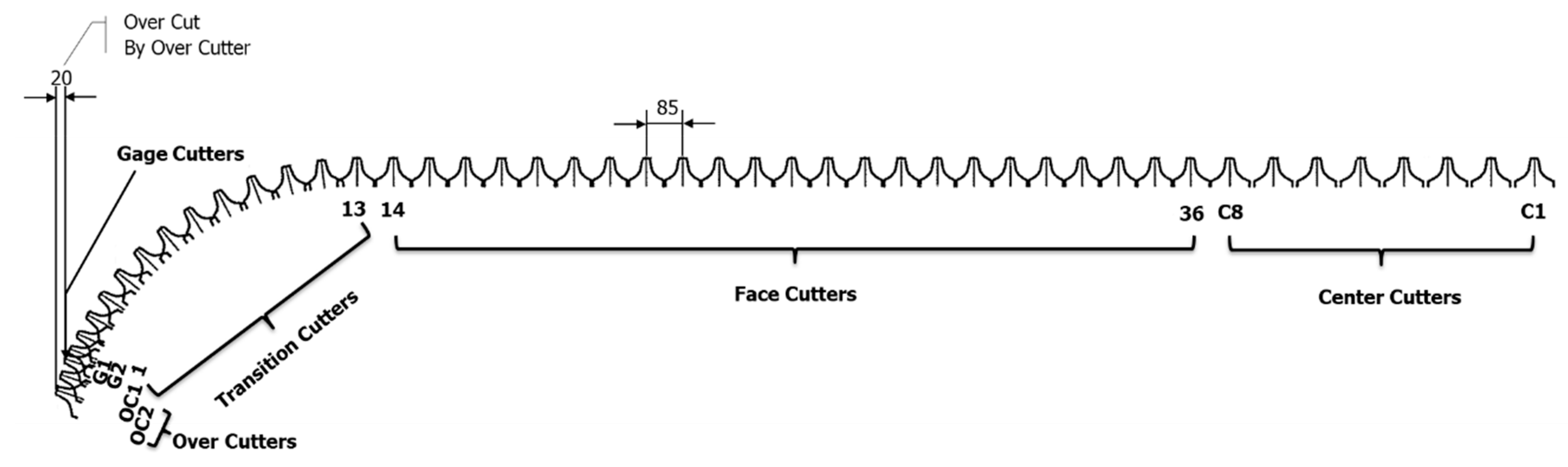
The disc cutter configurations of the cutterhead are depicted in
Figure 5. Disc cutters C1–C8 were double-disc cutters mounted at the central area of the cutterhead, and the others were single-disc cutters. Disc cutters No. 14–No. 36, called face cutters, were mounted at the cutterhead face. Disc cutters No. 1–No. 13, called transition cutters, were installed at the edge of the cutterhead, located at the curved portion of the cutterhead. Disc cutters G1 and G2 are gage cutters and were mounted at the same radius of the cutterhead. Disc cutters OC1 and OC2 are over cutters and were installed at the outermost portion of the cutterhead. The over cutters were mainly used for excavation at the tightly curved radius sections to negotiate the planned alignment. The theoretical wear limit of the 19 inch disc cutter was 30 mm. In the project, the allowable wear limit was set to 15 mm for centre, gage, and over cutters, and 25 mm for the face and transition cutters.
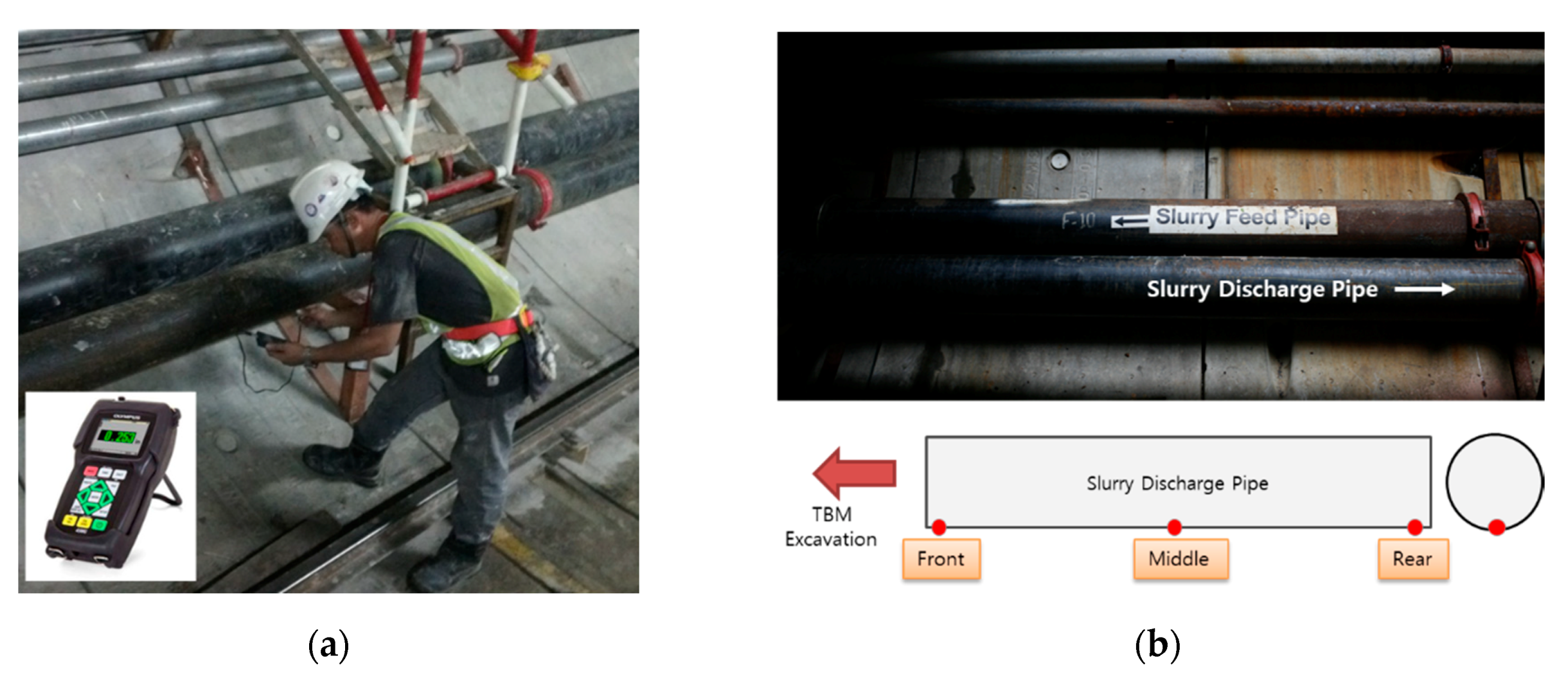
A carbon steel pipe with a diameter, length, and thickness of 20.32 cm, 6 m, and 13 mm, respectively, was used as the slurry discharge pipe at the project site. The thickness of the pipes was measured every week using an ultrasonic thickness gauge at the base where the maximum wear occurred. The pipes were rotated by approximately 120° once the residual thickness of the pipe reached 6 mm to maximize the life cycle of the pipes; otherwise, the pipes were replaced. Measurements were recorded at three locations, i.e., at the front, middle, and rear of each pipe, based on the direction of the excavation.
Figure 6 shows a site where the pipe thickness was measured and the location of the pipe measurement.
The slurry bentonite density ranged from 1.04 to 1.27 ton/m3 with an average value of 1.16 ton/m3, and the discharged material density varied from 1.14 to 1.29 ton/m3 with an average of 1.23 ton/m3.
3. Results
3.1. Wear of Disc Cutters
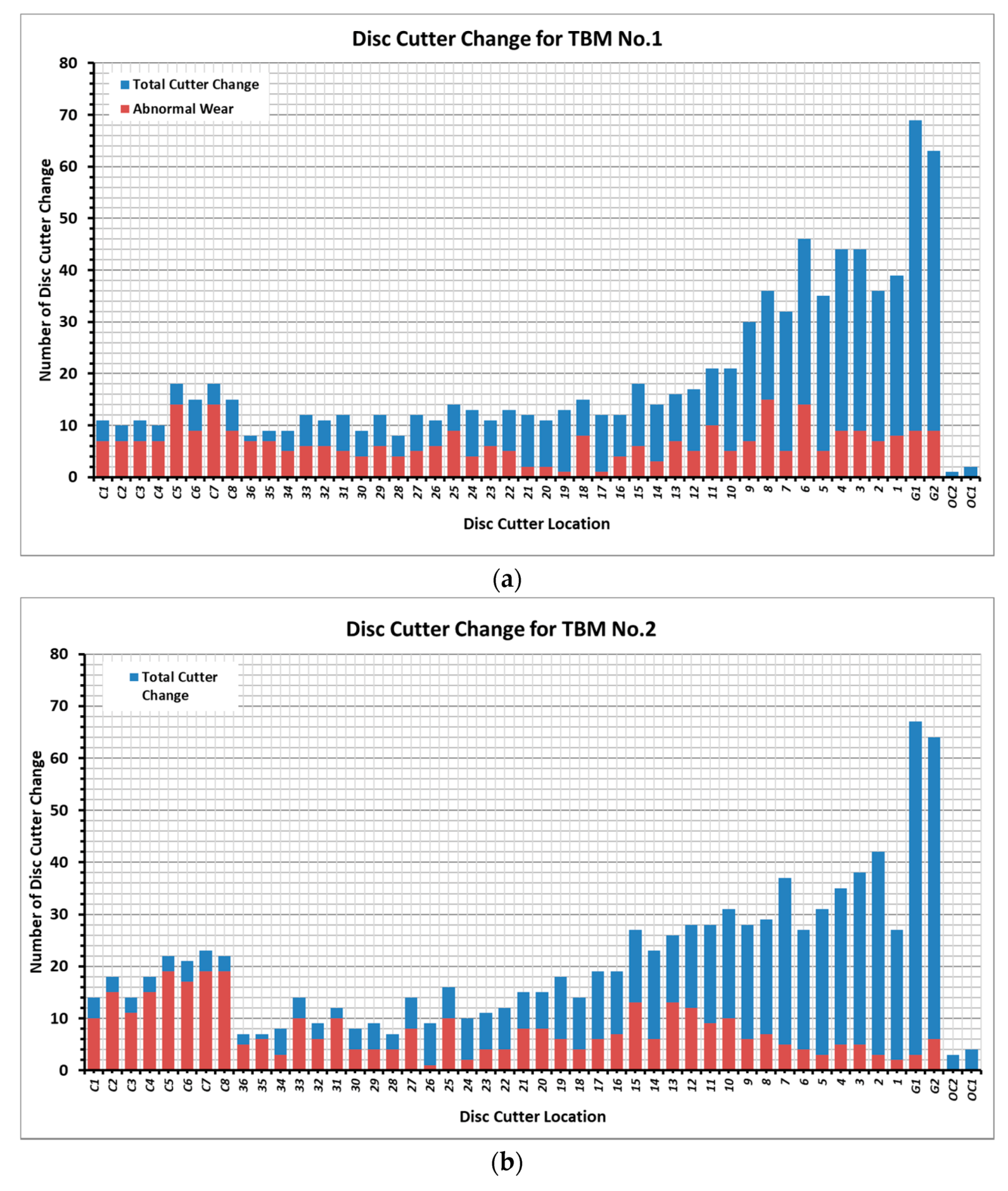
Figure 7 shows the number of disc cutters that were replaced in this study. A total of 833 disc cutters were replaced for TBM No. 1, which comprised 50 double-disc cutters and 783 single-disc cutters. In TBM No. 2, 952 disc cutters were replaced, comprising 144 double-disc cutters and 808 single-disc cutters. The number of double-disc cutters replaced for TBM No. 2 was approximately 2.9 times greater than the number of double-disc cutters replaced for TBM No. 1. This discrepancy in frequency of replacement is because there were more soil and mixed zones in the area where TBM No. 2 was excavated, resulting in frequent replacement due to increased frequency of abnormal wear.
There were two main reasons for the replacement of the disc cutters. One reason was the replacement due to normal wear, which was the case when the entire cutter ring gradually wore out and surpassed the allowable wear limit, following which it was replaced. The other reason was replacement because of abnormal wear, including flat wear, partial wear, cutter ring crack, bearing failure, and seal failure. It was discovered that 310 disc cutters were changed owing to abnormal wear for TBM No. 1. In TBM No. 2, 357 disc cutters were replaced owing to abnormal wear. The replacement of the disc cutters was related to the disc cutter position and installation radius.
As shown in
Figure 7, the number of disc cutter replacements increased with the installation radius. As the installation radius increased, the rolling distance of the disc cutter increased, and the disc cutter rotational speed also increased, such that the rate of disc cutter wear increased and thus warranted more frequent replacement. In particular, the gage cutters had an allowable wear limit of 15 mm, and were replaced more frequently than other cutters.
Among the total replacement of disc cutters for TBM No. 1, the replacement rate due to abnormal wear was 69% for the centre cutters, 41% for the face cutters, 25% for the transition cutters, and 14% for the gage cutters. Similarly, for TBM No. 2, the replacement rate owing to abnormal wear was 82% for the centre cutters, 46% for the face cutters, 21% for the transition cutters, and 7% for the gage cutters. It is evident that the occurrence of abnormal wear was related to the disc cutter position and installation radius. On the one hand, it appeared that more abnormal wear occurred in the centre cutters because of the smaller rotation radius; the rotation was not smooth, owing to friction in the tangent direction of the centre cutters. On the other hand, the rotation radius was relatively large for the transition of gage cutters, and the rotation of the disc cutter was smooth, so it appeared that more normal wear occurred.
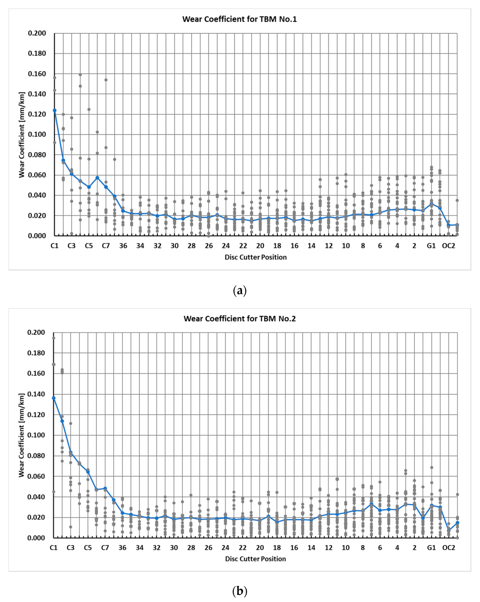
Figure 8 shows the relationship between the wear coefficient and the disc cutter position. The centre cutters show the highest wear coefficient values. The wear coefficient gradually decreases with the increase in disc cutter installation radius, and it then tends to increase again for the transition cutters. Over cutters were rarely used; hence, limited data were available for their analysis.
The reason for the centre cutter showing a high wear coefficient value was similar to the reason for the high abnormal wear. In the centre cutters, friction in the tangent direction of the cutters increased because the rotation radius was small, and the wear coefficient increased accordingly, owing to eccentric load and a reduction in cutter rotation. Additionally, when the curved section was excavated, the outer cutters were more in contact with the ground; this phenomenon also occurred when the straight section was excavated, and the alignment was maintained while the machine was continuously steered.
Table 4 lists the summary of the average values of the wear coefficient of the disc cutters with respect to the disc cutter position and weathering grade for Bukit Timah granite.
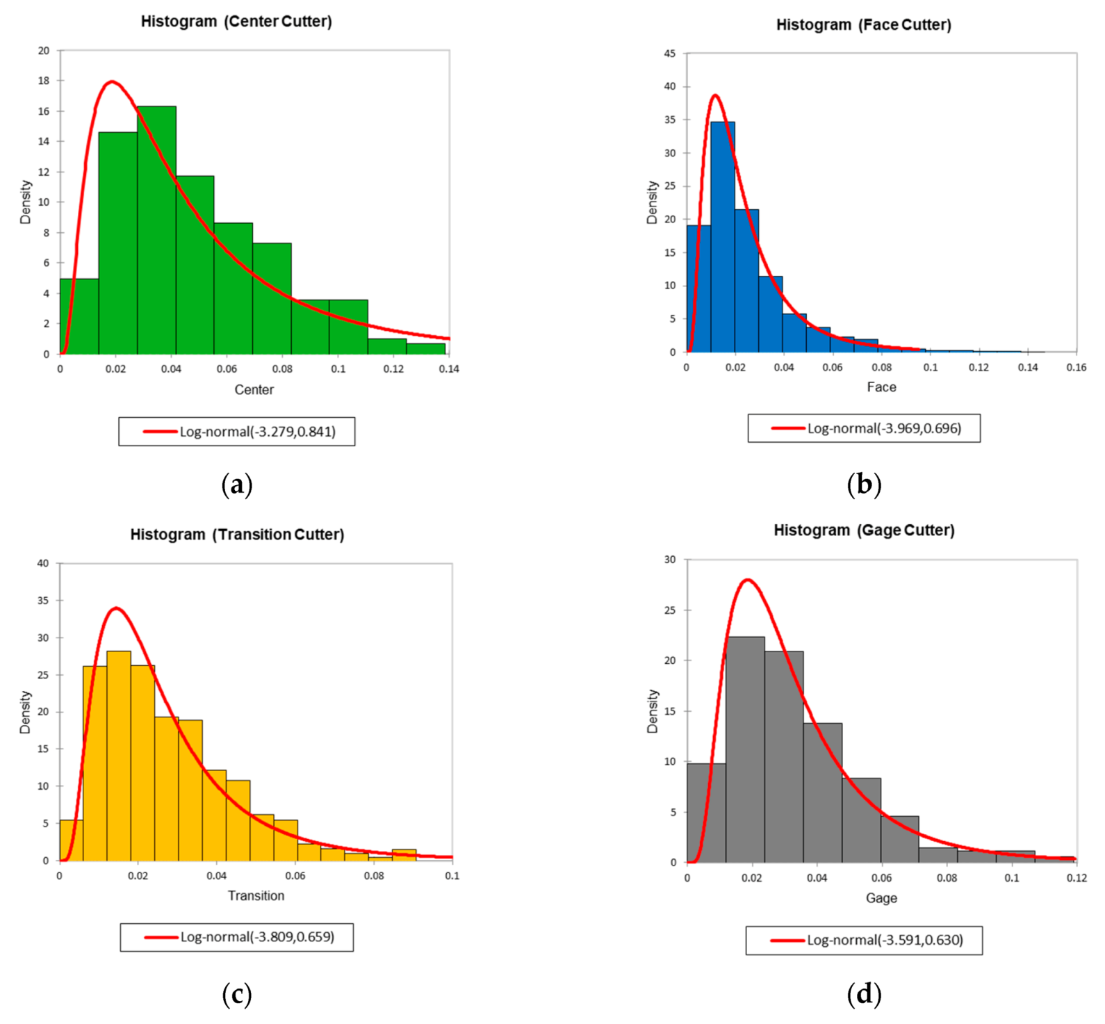
The wear coefficient distribution of the disc cutters according to disc cutter position under the overall ground condition is shown in
Figure 9. The wear coefficient distribution can be approximated using a log-normal distribution. As shown in
Figure 9, the average and mode, the value that appears most often for the wear coefficient of the disc cutters, are not the same. Under the overall ground condition, the modes of the wear coefficient of disc cutters were 0.0346, 0.0145, 0.0151, and 0.0175 for the centre, face, transition, and gage cutters, respectively. This indicates a wear coefficient mode of the average value of the wear coefficient of 73%, 60%, 56%, and 57% for the centre, face, transition, and gauge cutters, respectively.
3.2. Wear of Slurry Discharge Pipes
The slurry discharge pipes were rotated or installed while the pipe thickness remained at an average of 6.2 mm based on the recorded data. The pipe installation or rotation periods lasted for 115 days on average.
The daily wear rate of the slurry discharge pipes was 0.055 ± 0.048 mm/day on average, ranging from a minimum value of 0.011 mm/day to a maximum value of 0.243 mm/day. The wear rate per excavated distance had an average value of 0.017 ± 0.016 mm/m, with minimum and maximum values of 0.002 and 0.087 mm/m, respectively.
Table 5 lists the average values of the wear rate per excavated distance for the slurry discharge pipes with respect to the weathering grade of the Bukit Timah granite. The wear rates in weathering grades G(I) to G(IV) of Bukit Timah granite were similar. The wear rates for weathering grade G(V) of Bukit Timah granite, which was entirely weathered, and those for the mixed zone were 1.5 times higher than those for weathering grades G(I) to G(IV) of Bukit Timah granite. As can be observed in
Figure 6b, the thickness measurement was recorded at three locations: front, middle, and rear of each pipe. The average wear rate per excavation distance at each location was 0.017, 0.016, and 0.018 mm/m, for the front, middle, and rear, respectively. The difference in the wear rate with respect to measurement position within the same pipe was negligible.
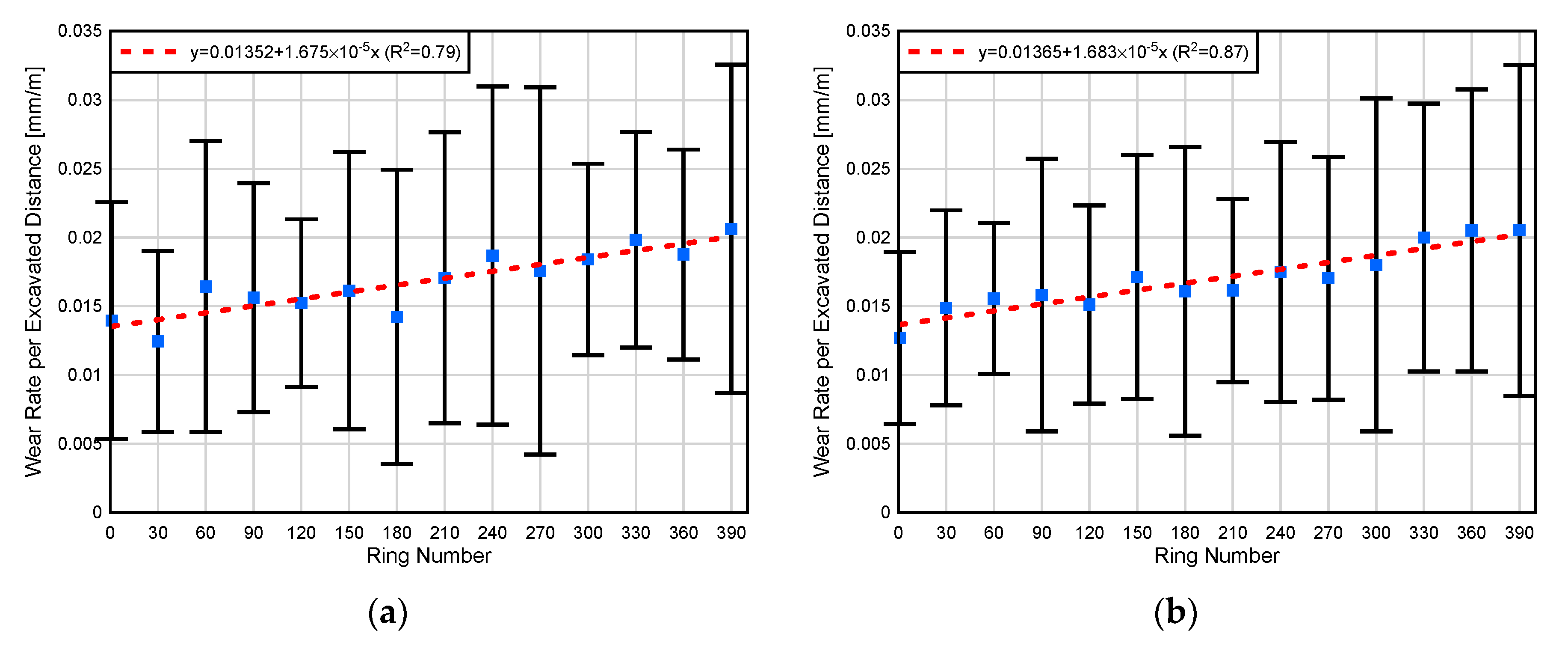
Figure 10 shows the wear rate per excavated distance according to the position of the ring where the pipe thickness was measured. As the TBM was used to install the rings after excavation, increasing the ring number suggests that the rings are closer to the TBM. As shown in
Figure 10, the wear rate closer to the TBM was generally higher. This higher wear rate indicates that rock chips (muck) became worn out as the moving path of the muck (including the rock chips) was greater, and the wear near the end of the pipe was less affected.
5. Conclusions
In this study, the effects of rock abrasiveness on the wear of disc cutters and slurry discharge pipes were investigated. The radial wear of disc cutters and the thicknesses of slurry discharge pipes were determined regularly at the TBM site located in Singapore.
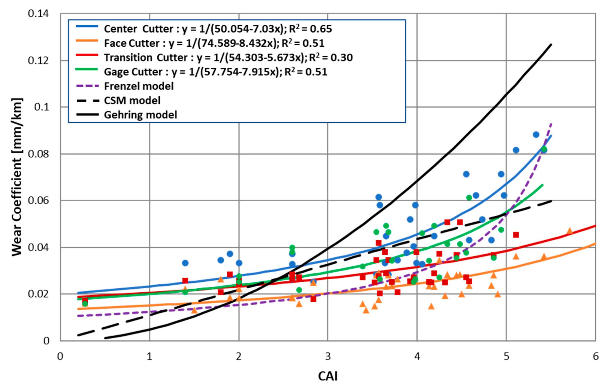
The wear of the disc cutter was measured based on the wear coefficient, and the wear coefficient of the disc cutters was investigated in various weathering grades of Bukit Timah granite. The wear coefficients of the disc cutters decreased with increasing weathering grade. The wear coefficient distribution of disc cutters can be approximated using a log-normal distribution, and a correlation between the CAI values and the wear coefficient was proposed.
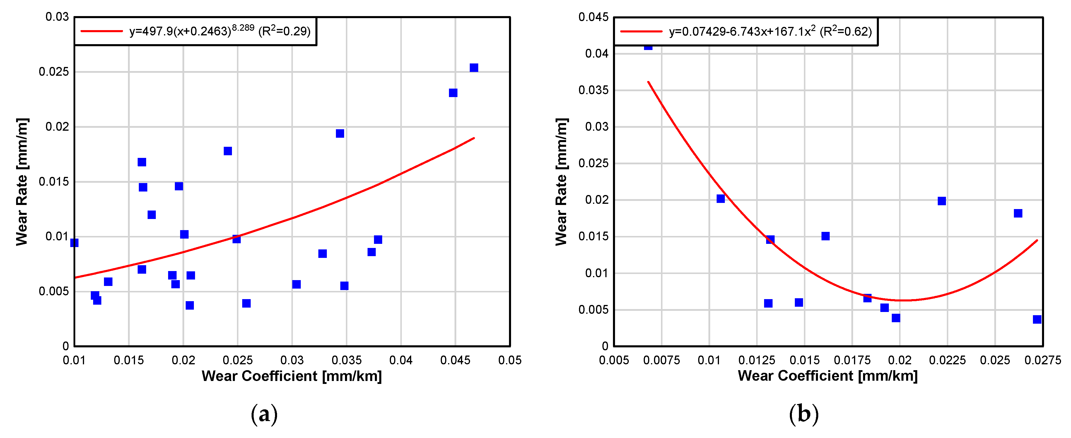
Furthermore, the average wear rates of slurry discharge pipes on Bukit Timah granite were determined from the loss of the pipe thicknesses. The wear rates in G(I) to G(IV) grade ground were similar or insignificantly different. The wear rates in G(V) grade and mixed ground were 1.55 times higher than those of G(I) to G(IV) grade ground. The correlation between the slurry discharge velocity and the wear rate was derived. A linear relationship between the wear coefficient and the wear rate of slurry discharge pipes exists between G(I) to G(IV) weathering grades of Bukit Timah granite. In contrast, a U-shaped parabolic relationship was established in the G(V) and mixed zone ground.
The accurate assessment of the effect of rock abrasiveness both on the wear of disc cutters and the wear rate in slurry discharge pipes, investigated in this paper, will play a key role in elucidating the factors that determine wear rate of excavation equipment, particularly in TBMs, and will encourage future research into preventing wear associated with rock abrasiveness in order to maximize lifespan and minimize construction costs and time.


