1. Introduction
Vibration created due to the unevenness of the road profile causes serious problems for the driver and the passengers. Especially, the vibration transmitted from the road to the human body at a low frequency causes damage to the spine in the long run. Vibrations create digestion problems, fatigue and discomfort while driving. Therefore, the seat suspension is mainly used to improve the driver’s comfort and reduce the intensity of the vibration transmitting to the human body.
A seat suspension system is broadly classified into three types, i.e., the passive seat suspension, semi-active seat suspension and active seat suspension. In the passive suspension, the ride comfort cannot be achieved without compromising the road-handling capabilities, as mentioned by Qin et al. [
1]. The fixed characteristics of the passive seat suspension decrease the versatility and prevent the damper from varying according to the working conditions. Unaune et al. [
2] revealed the design constraints associated with a passive suspension system using the quarter car suspension model simulations in MATLAB. A passive seat suspension also has similar design constraints and requires an optimum design of parameter-bound work within a limited frequency range [
3]. The active and semi-active seat suspension outperforms the passive suspension and overcomes the inadequacies of the passive seat suspension. The active seat suspension is comprised of an actuator which generates the force regulated by using the control law driven by signals measured with the help of the sensors. The controller controls the actuators to generate an adequate amount of force or dissipate the energy from the system. In spite of the great accuracy and the performance of the active seat suspension, disadvantages such as a high capital and running costs, a complicated design and the power requirements make it less popular and redundant for commercial vehicle application [
4]. The semi-active seat suspension was used widely because of its characteristics such as the semi-active suspension that does not require high power, while varying the damping force is one of the key features. Another crucial feature of the semi-active suspension is that it can even work as the passive suspension when the controller fails [
5]. Therefore, the semi-active seat suspension has the features of both the active and passive seat suspensions. The entirely new segment of the smart dampers provides wide applications in the industries owing to their versatility and promising performance as compared to the conventional oil-filled dampers. The magneto-rheological (MR) and electro-rheological (ER) dampers belong to the segment of smart dampers, as they can give a quick response and can change the damping in just a few milliseconds, as per real-time requirements [
6,
7]. MR dampers are highly reliable and can easily be maintained [
8]. Due to these reasons, semi-active seat suspension is considered in this work.
The performance of semi-active seat suspension has been studied by many researchers in the past. Choi and Han [
9] showed the performance of a robust sliding mode control on the electrorheological seat suspension with the human model. Bae et al. [
10] implemented the integrated semi-active seat suspension with the MR damper. One of the authors of this study has previously investigated the performance of semi-active suspension systems with different control strategies such as skyhook, groundhook and hybrid and reported the suitability of the control strategies for the desired application [
11]. Advanced and intelligent controls, e.g., fuzzy logic control (FLC), artificial neural networks (ANN), adaptive neuro-fuzzy inference system (ANFIS), evolving radial basis function networks and so forth have attracted the minds of researchers to controlled suspensions, owing to their better control performance [
12]. Mulla and Unune [
13] compared FLC and ANFIC control strategies with a traditional skyhook control for a semi-active suspension under International Organization for Standardization (ISO) road disturbance.
Singh and Aggarwal [
14] analysed the passenger seat vibration of the semi-active quarter car model with a hybrid Fuzzy-PID control. They reported that the proposed Fuzzy-PID approach offered a better performance in terms of passenger seat acceleration and displacement. Typical studies report the study of the active and semi-active seat suspension separately from the active and semi-active suspension of the vehicle. Bhattacharjee et al. [
15] applied the chaotic fruit fly algorithm for the tuning of PID. Choi and Han [
9] and Bae and Kang [
16] have studied the seat suspension with the human model without considering the vehicle suspension model. Gohari and Tahmasebi [
17] implemented the active control on the seat suspension while analysing the performance with various road disturbances, but only the seat suspension was considered. Swethamarai and Lakshmi [
18] implemented a Fuzzy-PID controller for the quarter car active suspension system with 3-DOF and reported that the Fuzzy-PID control reduced the driver’s body acceleration better than Fuzzy and PID controls, thus improving the ride comfort. However, they did not consider the seat suspension and human model in detail and they implemented Fuzzy-PID control for active suspension. Metered and Šika [
19] proposed a semi-active MR damper for the truck seat suspension. They used FLC to calculate the desired force of the MR damper, and a significant improvement in the ride comfort was observed. However, the approach of considering only the seat suspension with the human model while analysing the ride comfort is debatable. The study of an integrated model of the seat suspension, integrated with both the vehicle suspension and human model, is more pragmatic. In the integrated model, a semi-active seat suspension is considered to be mounted over the quarter car suspension model along and the human model. Rare work is available which considers the integrated model of the seat suspension with the human model and the vehicle suspension. Du et al. [
20] proposed the integrated model of the seat suspension with the human model. Rajendrian and Lakshmi [
21] implemented the fractional order terminal sliding mode controller (SMC) to reduce the head acceleration when considering the half car suspension model. Nevertheless, the analysis was done using active control in Reference [
20,
21]. As previously mentioned, the semi-active seat suspensions are the more preferred choice, as compared to the active seat suspensions. This encouraged current work to implement the integrated semi-active seat suspension with the human model.
The ride comfort of the rider is typically determined in terms of the acceleration of the human body in the vertical direction [
20]. To achieve a better ride comfort performance, an integrated semi-active seat suspension had been modelled including a 2-DOF semi-active seat suspension which is mounted over the 2-DOF quarter-car model and 4-DOF human model. The integrated model of the semi-active seat suspension is more practical because the road disturbances are altered by the vehicle suspension before coming to the cabin floor. Previous work which considered the direct supply of the road input to the cabin floor for analysing the performance of the seat suspension seems to be inappropriate and may provide inaccurate results. Wang et al. [
22] implemented the active seat suspension, however, they considered the human body and seat as a single entity. Similarly, Sathishkumar et al. [
23] considered only the seat while analysing the effect of semi-active force control in their semi-active seat suspension model. Thus, it further becomes important to integrate the human body model to get more accurate results, instead of just analysing the active or semi-active seat suspension.
From the literature review, it was observed that rare work is reported on the study of the integrated model of the semi-active seat suspension, consisting of both the vehicle suspension and the human models. Further, no work is available that studies the semi-active suspension system with such an integrated model. Further, the implementation of ISO road profiles while investigating such systems is missing. Thus, in this work, an integrated model of seat suspension comprising the semi-active quarter car suspension and human model is proposed. The MR damper, governed by the fuzzy logic-based self-tuning PID controller (FLST-PID), is implemented in the seat suspension. The FLST-PID determines the desired force and then it is compared with the force generated by the MR damper, and on the basis of the comparison when the MR damper, is switched either on or off. The FLST-PID controller is designed under the constraints of the suspension deflection limitation. Numerical simulations are performed to evaluate the performance of the integrated model on the various types of road profiles including the bump and ISO road profiles of different grades such as C, D and E-grades. Finally, the effectiveness of the semi-active suspension with the MR dampers is compared with the passive suspension on the bump and ISO road profile with different speeds that vary from 30 km/h to 120 km/h.
2. Integrated Seat Suspension and MR Damper Model
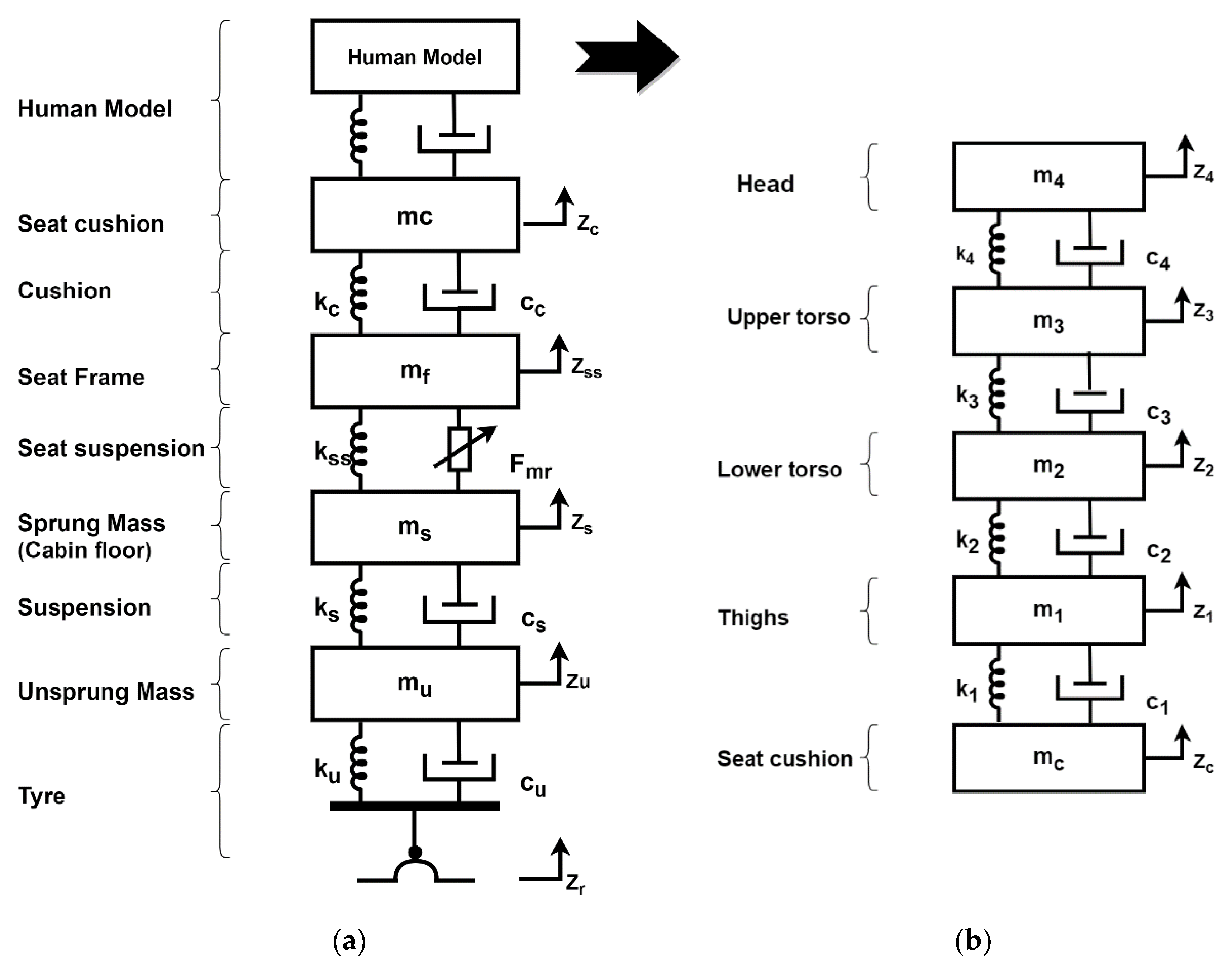
The proposed integrated semi-active seat suspension model, as shown in
Figure 1, consists of the quarter-car suspension model and the semi-active seat suspension with the MR damper mounted over it (see,
Figure 1a). The human model with 4-DOF was also taken into account. The human body was modelled as a 4-DOF system consisting of thighs, lower torso, high torso and head (see
Figure 1b). The arms and legs were integrated with the upper torso and thighs. In this paper, only the vertical motion of the system was considered for analysis.
The notations used for the integrated model are mentioned in
Table 1. The values of the parameters of the system for the numerical simulation were taken from Reference [
18].
The dynamical equations of the integrated model were derived using Newton’s second law of motion.
Equations (1) and (2) represent the dynamics of the quarter car model. The dynamics of the seat suspension are represented using Equations (3) and (4). Human body dynamics are represented by Equations (5) to (8). Here,
is the force generated by the damper. The damper force is given by Equation (9):
In this model, the viscous damping,, was considered as zero while analysing the performance of the MR damper. The MR damper generates the controlled force, . However, to compare the performance of the semi-active seat suspension with the passive seat suspension, a non-zero value of was considered only while analysing the passive seat suspension.
2.1. Dynamic Model of MR Damper
The MR damper model has been studied and applied by several researchers in the past. In this work, the Modified Bouc–Wen model of the MR damper is implemented. This model was adopted from Karkoub and Zribi [
24]. The force generated by the MR damper depends on the time history of the voltage in the coil of the damper, i.e., the supply voltage, and it also depends on the displacement of the damper,
:
The FLST-PID determines the supply voltage
of the MR damper. The force generated by the MR damper was computed by solving the Modified Bouc–Wen model using the voltage
and the
. The MR damper force has been computed by Equation (11):
where,
represents the accumulated stiffness as a spring with a constant value
and is used to simulate the hysteresis loop at low frequencies.
In Equation (12),
denotes the damping at the higher velocities. To control the stiffness at the large velocities another spring with the constant
was introduced in Equation (12). Furthermore,
denotes the initial displacement. The internal moments in the MR damper is signified by Equation (12). The hysteresis loop of the MR damper is presented by
, which is known as the evolutionary variable. The behaviour of the evolutionary variable is governed by Equation (13):
The shape of the hysteresis loop can be synchronized by
,
and
. The force generated by the MR damper was controlled by the input
. The control input is associated with the amount of voltage supply
by the following equations, Equations (14)–(17).
The effect of the sensor delays is not considered in this work.
2.2. MR Damper Controller
The force generated by the MR damper ‘
’ depends on the control input
which is related to the supply voltage
. The supply voltage was controlled by the Heaviside step function adopted from Dyke et al. [
25]. The governing equation of the Heaviside step function is given by Equation (18):
Here, in Equation (18) is the saturation voltage of the coil in the MR damper and is the Heaviside step function. The value of the supply voltage depends on , i.e., the desired controlled force, which is estimated by the FLST-PID and the force produced by the MR damper. In Equation (19), are the PID gain which were determined through fuzzy logic. is the sprung mass velocity error. Equation (19) allows to calculate the controlled force (desired force) which feeds into Equation (18). Equation (18) permits to determine the input voltage of the MR damper.
When > , it means that the requirement of the control force (desired force) is greater than the force produced by the MR damper . Therefore, the voltage must be increased to its maximum value to satisfy the requirement. When , the control force (desired force) is equal to the MR damper force . There should be no change in the voltage to maintain the voltage. In cases other than those mentioned above, the voltage remains zero. In this case, there is no requirement for activating the MR damper.
If the force produced by the MR damper is equal to the desired control force, then the supply voltage should remain constant [
24].
If the magnitude of the MR damper force is less than the desired force and if both forces are in the same direction, then the applied voltage is the maximum to increase the force generated by the MR damper. Otherwise, the supply voltages are sets to zero [
24]. The parameters of the MR damper model used for the numerical simulation were taken from References [
19,
26] and are mentioned in
Table 2.
3. Controller Design for the Semi-Active Seat Suspension
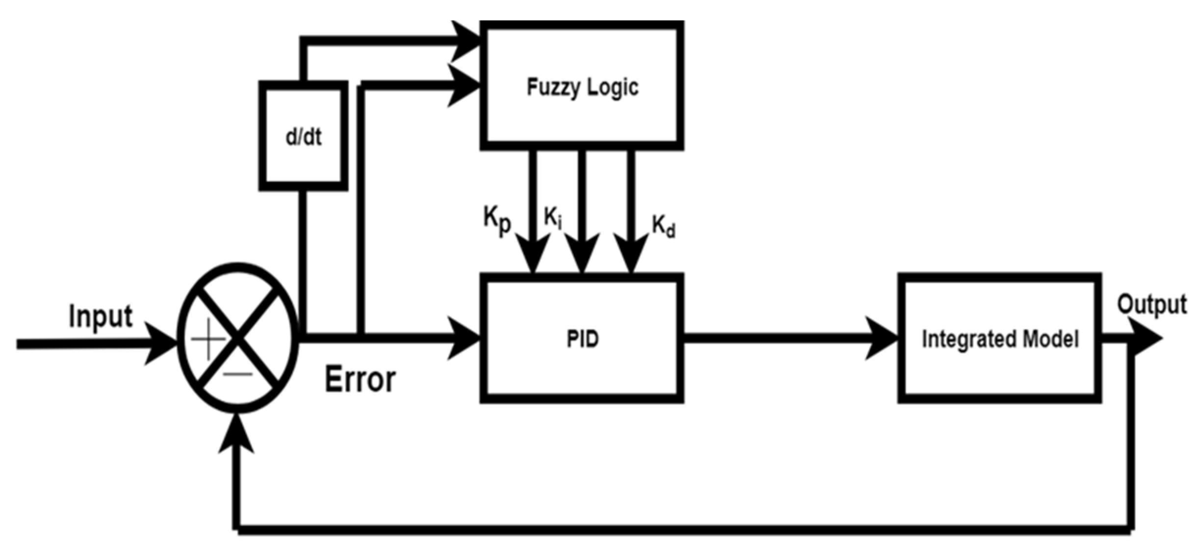
To determine the desired force required to minimize the transmissibility of the vibration to the human body for a comfortable ride, a proper controller design is essential. Therefore, in this work, the self-tuning PID controller based on fuzzy logic has been implemented. The PID controller is one of the most popular and highly used control designs in the industry. The performance of the PID controller is based on the optimal values of gains. However, as the operating conditions change and the system parameters change, the PID controllers show unwanted overshoots, and this sometimes leads to a slow response when subjected to external disturbances [
19]. To overcome such a drawback, the FLST-PID has been implemented in this work. The FLST-PID tunes the gain on the basis of fuzzy logic, which provides the advantage of the auto-tuning of the proportional, integral and derivative gains for the PID controller for a better performance when subjected to varying external disturbances [
27]. This control takes the error and error derivative as the input and determines suitable values of the proportional gain (
Kp), integral gain (
Ki) and derivative gain (
Kd) as the output [
27,
28]. The values of
Kp,
Ki and
Kd were tuned by the fuzzy logic. The block diagram of the FLST-PID is shown in
Figure 2.
The state variables, sprung mass velocity and accelerations used in this work are measured by using velocity sensors or accelerometers. The sprung mass velocity and acceleration are measurable typically and, hence, considered as the input variables. Therefore, the sprung mass velocity
error, i.e., (
-0), is denoted as ‘
Ve’, and the error of derivative (
-0) is denoted as ‘
Ce’, i.e., the sprung mass acceleration (
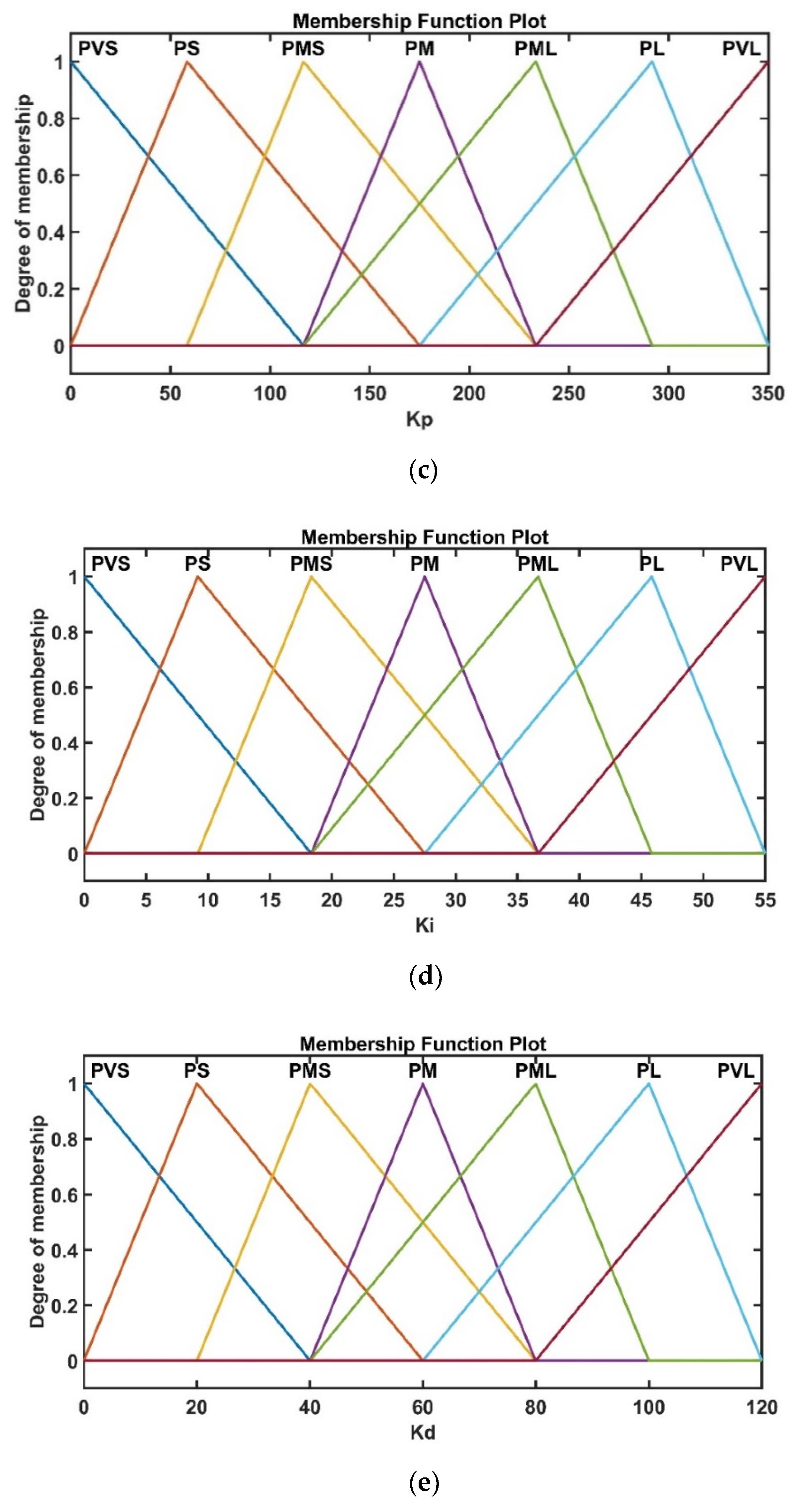
), were chosen as inputs. For the fuzzy logic design, the linguistic variables of the input membership functions were taken as: Negative Large (NL), Negative Small (NS), Zero (ZE), Positive Small (PS) and Positive Large (PL). Similarly, the linguistic variables of the output membership functions were taken as: Positive Very Small (PVS), Positive Small (PS), Positive Medium Small (PMS), Positive Medium (PM), Positive Medium Large (PML), Positive Large (PL) and Positive Very Large (PVL). Membership functions were chosen on the basis of the literature [
14,
18,
27,
28], the trial and error method and the experience of the authors and are shown in
Figure 3.
The triangular membership functions were considered for the input as well as the output variables. The fuzzy rules for tuning and gain were based on the error and the derivative of the error. The output was computed by the centre average defuzzification method. For instance, in the rules of
Kp, provided in
Table 3, if the velocity error
Ve is in the region of NL and its change
Ce is also in the NL region, then, according to the fuzzy mapping rule, the output will be in the PVL region. In other words, for very large NE, there must be a PL value of
Kp to minimize it. For
Ki and
Kd similar criteria logic was used to determine the respective gains. Hence, as the velocity error or the acceleration error changes its region, at the same time, the region of output
Kp,
Ki and
Kd change according to the rules described in
Table 3,
Table 4 and
Table 5. Furthermore, as the input changes, the region of the value of all three gain values change according to the fuzzy rule. The PID gains change according to instantaneous error values, therefore, this is known as a self-tuning PID controller based on fuzzy logic.
The centre average method, also known as the centroid method, determines the crisp value of the output, taking into consideration, in a weighted manner, all the influences obtained from the rules fired by the particular state of the inputs at a certain moment. This method is adopted from the mechanics and are specific to calculate the abscissa of the centroid [
29]. Hence, as the input variables change, then the output variables change according to the rule shown in
Table 3. From these rules, the values of the PID gains were computed. The rules for tuning
Kp, are shown in
Table 3.
The rules for tuning
Ki are shown in
Table 4.
The rules for tuning
Kd are shown in
Table 5.
The semi-active control of the integrated seat suspension model with FLST-PID and the Heaviside function’s block diagram is shown in
Figure 4.
4. Numerical Simulation
To validate the effectiveness of the integrated semi-active seat suspension, numerical simulations were performed for the different road profiles. The numerical simulations were computed using MATLAB. The ode45 was used as the solver with a step size of 0.04 s. The performance of the semi-active and passive seat suspension was compared on the bump profile and the ISO road profiles of the different grades such as the C, D and E-grade with the varying speed from 30 km/h, 60km/h and 90 km/h. The bump profile applied to the vehicle’s wheels were determined by using Equation (20):
More information on Equation (19) can be found in Reference [
30].
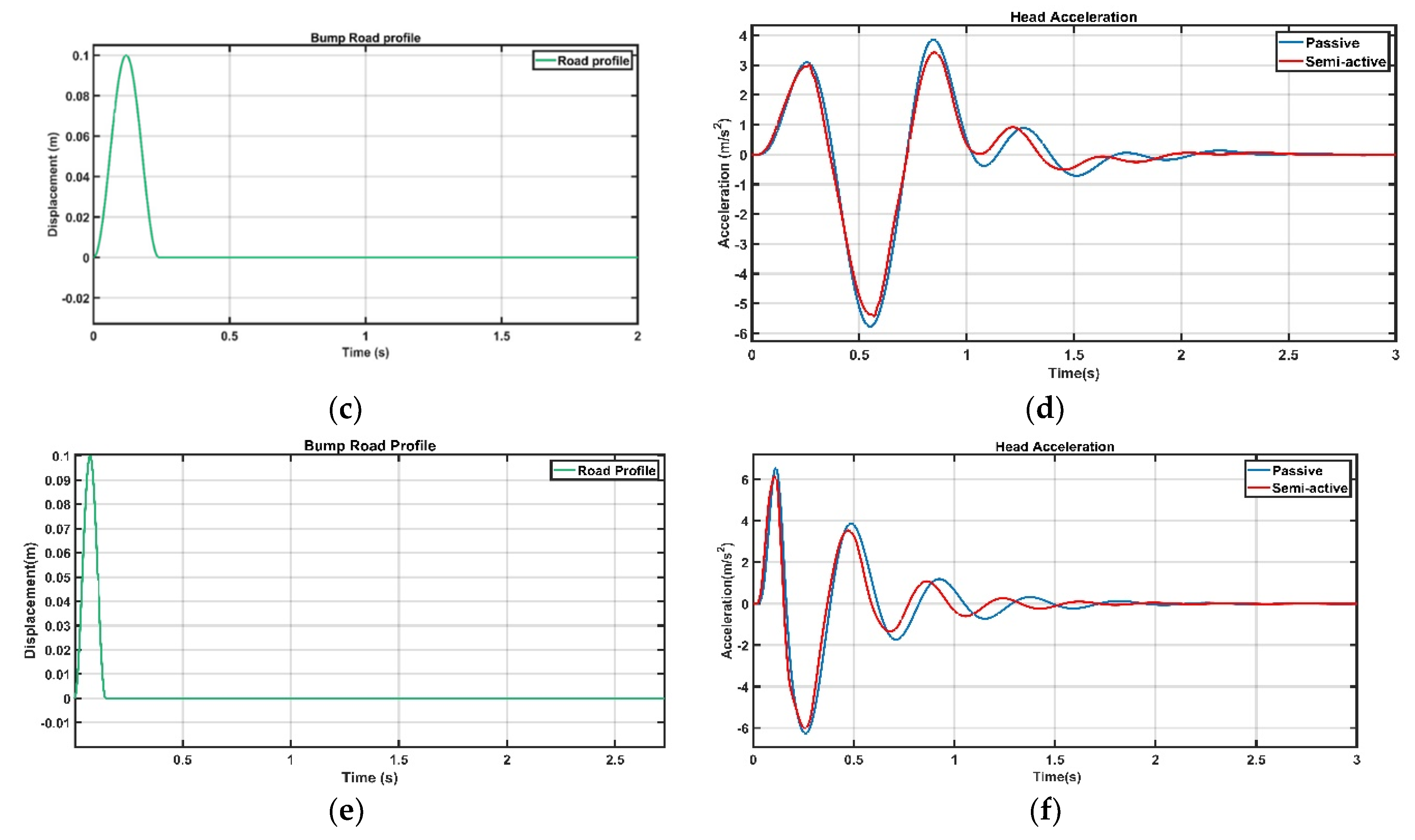
The bump profile applied to the vehicle’s wheels are shown in
Figure 5. The bump road profiles at 30km/h, 60 km/h and 90 km/h are shown in
Figure 5a,c,e, respectively.
In Equation (20),
is the amplitude of the bump, which is 0.1 m, the velocity
) of the vehicle which is taken as 30 km/h. The driver’s head acceleration response for the bump input at different velocities for semi-active and passive seat suspension is shown in
Figure 5b,d,f. In
Figure 5, passive represents the passive seat suspension without any controlled damper, whereas semi-active represents the semi-active seat suspension with the MR damper controlled by FLST-PID. For instance, the semi-active seat suspension reduces the peak-to-peak value of the head acceleration by 7.68%, as compared to that of the passive seat suspension only, improving the ride comfort in case of a bump road profile at 30 kmph vehicle speed. Although this percentage reduction is value is not very large; such an observation is due to the inclusion of the vehicle suspension model in the proposed integrated seat suspension model. In this study, we give the bump profile with a 0.1 m amplitude road input to the wheels of the vehicle and suspension damper, suppressing the vibrations at first, and then the displacement of the sprung-mass
Zs actually serves the input to the seat suspension system. Much previous work reports road input directly applied to the seat suspension as the disturbance and this may lead to larger values of percentage reduction of the head acceleration of the semi-active seat suspension, as compared to that of thee passive system. Therefore, the proposed approach of the integrated seat suspension with a vehicle suspension and human model looks more pragmatic. Gad et al. [
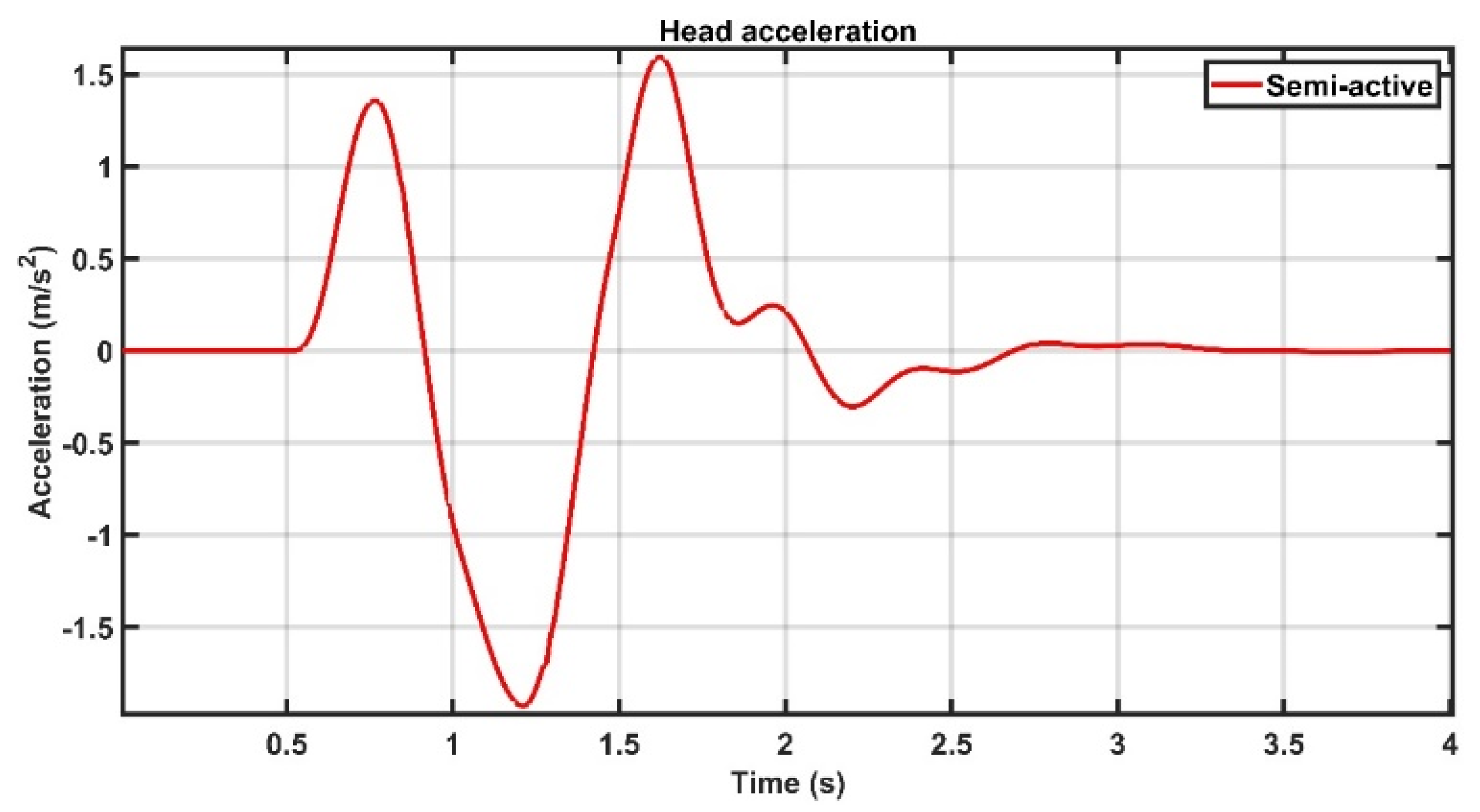
31] proposed a semi-active MR seat suspension system with a human body model without considering the vehicle suspension in their model. They simulated their model for bump road input and used a fractional-order proportional-integral-derivative (FOPID) with a genetic algorithm controller for their semi-active seat suspension system. They reported that the peak-to-peak value of the human head acceleration came out at 7.9442 m/s
2. We simulated our model with the same input as that of Gad et al. and found the peak-to-peak value of the head acceleration to be 3.523 m/s
2 (see
Figure 6) and, thus, show a reduction of ~55% (both studies use semi-active suspension models). This result shows the effectiveness of the proposed model as well as the controller implemented. The model parameters for both studies are same, however, they did not consider vehicle suspension in their study. This justifies the need to consider integrated seat suspension modelling.
Table 6 shows the comparison of the performance of passive and semi-active seat suspension for the bump road for the peak-to-peak values of the human body parts, in other words, the head, upper torso, lower torso and things.
Table 6 also shows the percentage improvement in the peak-to-peak accelerations owing to a semi-active seat suspension, as compared to the passive system. Overall, it was found that a semi-active seat suspension reduces the acceleration values and, thus, improves the ride comfort.
The force generated by the MR damper is shown in
Figure 7. It can be noted that the maximum force generated by the MR damper is 500 N, which is under the constraint of the limited seat suspension stroke. This constraint is quite practical to consider in the design, otherwise the suspension might collide with the end’s stop [
32].
From
Figure 8 it can be observed that the stroke length for the MR damper is within the range of ±20 mm which is acceptable for the seat suspension [
19].
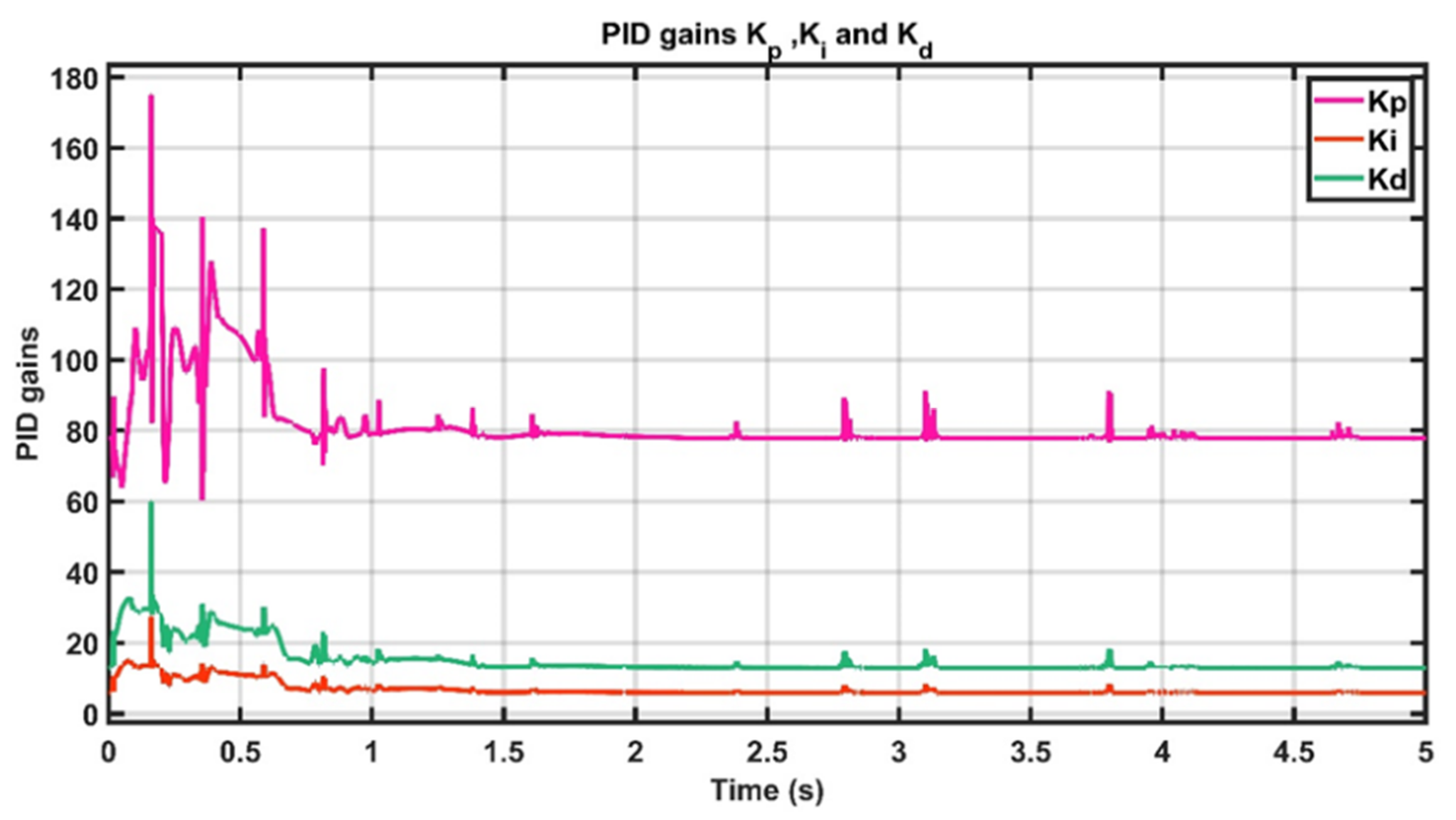
The calculated values of the PID gains with the time for the bump input are shown in
Figure 9.
The FLST-PID can easily be implemented to design the suspension module and can be integrated with the electronic control unit (ECU) of the car which is responsible for other electronic controls in the vehicles. The three phases of fuzzy logic, i.e., fuzzification, fuzzy inference engine and defuzzification, can be embedded into the circuit. The suspension model receives the feedback from the accelerometer or velocity sensors fitted at the sprung mass and the seat of the drivers. Thus, for FLST-PID, the inputs coming from such sensors can be directed to the fuzzification board. Then, in the fuzzy inference engine, the fuzzy logic rules that depend on the analogue signals’ input voltages ranging from − 5 V to + 5 V can be implemented, generating an analogue voltage distribution on the signal lines. Such a voltage distribution is characterized by the membership functions of the individual inference result. The membership function of the final fuzzy inference result can be applied to the buffer amplifier array (input stage of defuzzifier), through a data bus of analogue signal lines (rules) and, then, the outputs fed to the two resistor arrays, one of which produces a weighted sum of the membership function, and the other, a normal sum of two output data (scalar values). These outputs are then transferred to the analogue divider to produce a centre of gravity of the membership function applied to this block. Finally, the defuzzifier board groups output signals from the rule boards to determine the PID gains and compute the controlled force. By doing an if–else computation, the Heaviside function controller accordingly provides the signal to the power transistors whether to switch the solenoid of the MR Damper on and off. Thus, the FLST-PID can compute the amount of the force required to minimize the vibration. For further reading, please refer to Reference [
33].
To further validate the performance of the semi-active seat suspension, a random road profile was used as the input. Here, to check the effectiveness of the controller, the different speeds of the vehicle, i.e., 30 km/h, 60 km/h, 90 km/h and 120 km/h for each grade of the road were considered.
For a constant speed in the time domain, the power spectral is the white noise signal and the spectral density of the signal is given by Equation (21):
According to the ISO 2631 standard, the value of
for the C-grade = 64
, D-grade = 256
and for the E-grade = 1024
,
is the space frequency which is taken as
and
is the velocity in
[
30]. The random road profile can be generated using Equation (22):
Here,
is the white noise signal,
denotes the time. One sample of the random road profile of the E-grade at 120 km/h is shown in
Figure 10.
The performance of the passive seat suspension and the proposed integrated semi-active seat suspension on the random road profile has been compared on the basis of peak-to-peak value of the head acceleration. The speed of the vehicle was varied from 30 to 120 Km/h with an interval of 30 km/h. The performance comparison of integrated semi-active seat suspension with passive seat suspension in terms of peak-to-peak value of head acceleration for C-grade, D-grade and E-grade road profiles at different vehicle speeds is shown in
Figure 11.
It can be observed from
Figure 11 that the semi-active seat suspension outperforms the passive seat suspension in terms of the peak to the peak value of the head acceleration at considered vehicle speed values. From these results, it is reasonable to claim that the semi-active set suspension improves the ride comfort by reducing the head acceleration as compared with the passive seat suspension.
5. Conclusions
In this work, an integrated semi-active seat suspension mounted over a quarter car with the human model was implemented. The human model was broken down into 4-DOF including thighs, lower torso, upper torso, and head. The MR damper was implemented for the semi-active seat suspension and the controller force was determined by the fuzzy logic-based self-tuning PID controller. The Heaviside step function was used to track the desired damper force and supply the required voltage to the MR damper. The performance of the semi-active seat suspension and the passive seat suspension was compared using different road profiles such as bump input and the ISO road profile with the different grades and the vehicle’s speed.
The simulation results show that the MR damper seat suspension can significantly attenuate the vibration transmitting to the human head. For the bump road input profile, the semi-active seat suspension shows 9.49% reduction in the peak-to-peak value of head acceleration, as compared to that of passive seat suspension, thus, improving the ride comfort. Similarly, for the C-grade road profile there is an average of 8.3% reduction in the peak-to-peak values of head acceleration at different speeds. Furthermore, for the D and E-grade road profiles, the peak-to-peak head accelerations were reduced by 7.8% and 6.5%, respectively. A notable reduction in peak-to-peak values of head accelerations were observed for the proposed integrated semi-active suspension, as compared to the passive seat suspension. In future work, the effectiveness of the proposed integrated semi-active seat suspension model on the ride quality, in terms of seat effective amplitude transmissibility, vibration dose value, and crest factor, are required to be investigated considering the frequency domain analysis. Further, the effect of sensor delays in the proposed models’ performance also needs to be investigated.


