Article

Nickel-Based Structured Catalysts for Indirect Internal Reforming of Methane

1
Department of Chemical Science and Technology, University of Rome Tor Vergata, Via della Ricerca Scientifica 1, 00133 Rome, Italy
2
Department of Energy Technologies, Italian National Agency for New Technologies, Energy and Sustainable Economic Development (ENEA) Casaccia RC, Via Anguillarese 301, 00123 Rome, Italy
3
Department of Science, University of Rome “Roma Tre”, Via della Vasca Navale 79, 00146 Rome, Italy
4
Institute for Photonics and Nanotechnologies—CNR (National Research Council of Italy), Via Cineto Romano 42, 00156 Rome, Italy
*
Author to whom correspondence should be addressed.
Appl. Sci. 2020, 10(9), 3083; https://doi.org/10.3390/app10093083
Submission received: 8 April 2020 / Revised: 20 April 2020 / Accepted: 22 April 2020 / Published: 28 April 2020

Abstract

:
A structured catalyst for the dry reforming of methane (DRM) was investigated as a biogas pre-reformer for indirect internal reforming solid oxide fuel cell (IIR-SOFC). For this purpose, a NiCrAl open-cell foam was chosen as support and Ni-based samarium doped ceria (Ni-SmDC) as catalyst. Ni-SmDC powder is a highly performing catalyst showing a remarkable carbon resistance due to the presence of oxygen vacancies that promote coke gasification by CO2 activation. Ni-SmDC powder was deposited on the metallic support by wash-coating method. The metallic foam, the powder, and the structured catalyst were characterized by several techniques such as: N2 adsorption-desorption technique, X-ray diffraction (XRD), scanning electron microscopy with energy dispersive X-ray spectroscopy (SEM-EDX), focused ion beam (FIB), temperature programmed reduction (H2-TPR), and Raman spectroscopy. Catalytic tests were performed on structured catalysts to evaluate activity, selectivity, and stability at SOFC operating conditions.

Graphical Abstract

1. Introduction

Biogas is an attractive renewable energy source, alternative to fossil fuels, produced by the anaerobic fermentation of organic matter, mainly consisting of methane (50–80%) and carbon dioxide (25–50%). The CO2 reforming of CH4 reaction Equation (1), called dry reforming of methane (DRM), is an interesting strategy in the context of biogas valorization to syngas. Many research efforts have been focused on catalytic aspects and engineering of DRM process [1,2,3,4].
CH 4 +   CO 2   2 H 2 + 2 CO   Δ H 0 = 247   kJmol 1
The syngas, or synthesis gas, is a mixture of hydrogen and carbon monoxide, used as a feedstock in the chemical industry for the synthesis of a wide range of chemicals and fuels but it can be also used to feed solid oxide fuel cells (SOFCs) [5,6,7]. DRM is an extremely endothermic reaction and it requires temperatures as high as those of SOFCs’ operation to attain reasonable yield of syngas. Thus, SOFCs powered by biogas can act as efficient devices for biogas-electricity conversion [8,9]. Two approaches to SOFC operation can be considered: One is the external reforming (ER) mode, when the endothermic CO2 reforming of CH4 (DRM) and the electrochemical reactions are operated in different units, and another is the internal reforming (IR) mode, when DRM reaction and the oxidation reaction are operated together in a single unit. A further distinction can be done for the internal reforming operation: Direct internal reforming (DIR) and indirect internal reforming (IIR). In IIR operation the reformer is in contact with the anode side of a fuel cell, potentially still providing intimate heat transfer between the reformer and the SOFC [10].
The aim of this work is the design of an efficient structured catalyst for the DRM as a biogas pre-reformer in IIR-SOFCs.
Structured catalysts for hydrogen production from biogas have received large attention for their specific characteristics such as: High geometric surface area and low pressure drop [11,12,13,14]. Structured systems on different configurations (foams, honeycombs, monoliths) showed several advantages compared to conventional packed bed reactors [15,16,17,18]. For our purpose, a suitable metallic structured support has been chosen as substrate for catalyst deposition. Metal foams are recommended supports for their open-cell structure, high thermal conductivity (fundamental in case of endothermic reactions), high temperature stability, and mechanical strength. Their high porous texture allows a better mass and heat exchange and promotes a high contact efficiency between catalyst particles and gases. Other important requirements are corrosion resistance, low pressure drop, and large surface/volume ratio [19,20,21]. The main critical issue for structured catalysts’ fabrication is the deposition of uniform catalyst layers, able to withstand reaction conditions. Among different deposition methods, the wash-coating into a dispersion is widely considered the best fabrication technique [8,22,23].
Among catalyst powders, nickel-based catalysts are highly active for the DRM reaction, but they are quickly deactivated by coking under certain conditions [8,24,25,26,27].
Concomitant side reactions take place with DRM, such as reverse water gas shift reaction (RWGS) Equation (2) that lowers the H2/CO ratio, methane decomposition Equation (3), and Boudouard reaction Equation (4), both deactivating the catalyst due to the carbon deposits:
CO 2 +   H 2   H 2 O   +   CO       Δ H 0 = 41   kJmol 1
CH 4     C   + 2 H 2     Δ H 0 = 75   kJmol 1
2 CO     C   +   CO 2     Δ H 0 = 172   kJmol 1
Recently, some authors of the present paper reported that nickel supported on samarium doped ceria (SmDC) is a highly performing catalyst showing remarkable carbon resistance. The oxygen vacancies introduced by Sm enhanced the CO production, leading to a high O uptake by the supports, favoring the coke oxidation [28,29]. The catalytically active Ni particles are involved in the chemisorption of CH4 and CO2, producing the intermediates, CHx and O*, that subsequently form CO and H2. However, the progressive dehydrogenation of CHx species may form carbon residues, which can cause the deactivation of the catalyst. The Ni species interact strongly with CeO2, and this interaction is favored in CeReOx solid solutions by the oxygen vacancy formed by the aliovalent dopants (i.e., La, Sm, and Pr). These oxygen vacancies allow the activation of CO2, producing CO and O* species which can be transferred quickly near the Ni sites favoring the oxidation of the carbon residues, limiting the deactivation of the catalyst. Thus, the deposited carbon amount during the DRM was related to the nature and the amount of oxygen vacancies [1,30,31,32,33].
In this work, Ni-Ce0.85Sm0.15O2−δ was used as catalyst powder and deposited on NiCrAl foam by wash-coating to fabricate structured catalysts for DRM.
Powder, support, and final structured catalyst were investigated by using different techniques such as: X-ray diffraction (XRD), scanning electron microscopy with energy dispersive X-ray spectroscopy (SEM-EDX), focused ion beam (FIB), temperature programmed reduction (H2-TPR), and Raman spectroscopy. Catalytic tests for DRM were performed to evaluate activity, selectivity, and stability at SOFC operating conditions.

2. Materials and Methods

Ni-Ce0.85Sm0.15O2-δ powder (Ni nominal loading 5 wt.%) was synthesized according to the citrate auto-combustion method. Stochiometric amounts of metal nitrates Ni(NO3)2∙6H2O, Ce(NO3)3∙6H2O, and Sm(NO3)3∙6H2O and citric acid monohydrate (CA), with a molar ratio CA/(Ni2++Ce3++Sm3+) = 2, were dissolved in water and well stirred. NH4OH solution (28 wt.%) was added until pH value 8 was reached. The solvent was evaporated at 100 °C yielding a gel, then the temperature was increased up to 250 °C to ignite the auto-combustion. The obtained dark powder was calcined in air at 750 °C for 5 h with a heating rate of 5 °C min−1. After calcination, the powder was milled using a planetary ball mill (Fritsch, Mono Mill Pulverisette 6) at 450 rpm for 3 h. Grinding balls of ZrO2 were used in a 35-mL volume of 2-propanol for a weight of ca. 3 g of powder. The chemical composition was determined by energy dispersive X-ray EDX analysis, as previously reported [29]. The powder was dried at 70 °C overnight. Hereafter, sample was named Ni-SmDC (samarium doped ceria).
Structured catalyst was prepared by wash-coating method, dipping disks (diameter 0.9 mm, thickness 2.5 mm) of NiCrAl foam into a slurry of catalyst powder. The NiCrAl alloy foam (pore size 800 µm, porosity 90%, geometric surface area 6000 m−1, density 1250 g·m−3) was supplied by Alantum. Commercial foams were provided with a passivated surface as revealed by a bumpy surface along the struts [19].
A stable slurry of catalyst powder was optimized by choosing solvent, dispersing agent, and organic binder. Specifically, 8 wt.% of triethanolamine, related to catalyst mass, was used as dispersant and 2-propanol was used as solvent. In addition, a low content (2 wt.%) of polyvinyl butyral resin (PVB), named as BUTVAR B-98, was used as organic binder to improve the coating adhesion. The solution was prepared by dissolving triethanolamine and PVB in 2-propanol by ultrasound bath for 30 min at room temperature. Catalyst powder was added to the solution and the slurry was prepared using an ultrasonic processor sonication (Sonics Vibra Cell VCX-600, Newtown, CT, USA), operating for 5 min in pulse mode, to reduce loss of solvent due to heating. Hence, the deposition process was carried out by dipping the foams in the resulting slurry. After dipping, the slurry excess was blown away by an air gun. Multiple coatings cycles were performed to obtain the deposition of a double or a triple layer of catalyst. An intermediate calcination step at 500 °C for 5 h between two subsequent coating cycles and a final calcination at 750 °C for 5 h were performed to remove the binder and ensure a good adhesion. The nickel-based catalyst loading was evaluated by the weight difference between the bare and the coated support. Coating adhesion strength was assessed by the weight loss after sonication in 2-propanol (20 min) and drying at 120 °C for 2 h. The weight loss was 0.4%.
The phase composition of powders was investigated by X-ray diffraction (XRD) using a Scintag X1 diffractometer equipped with a Cu Kα (λ = 1.5418 Å) source and the Brag-Brentano θ–θ configuration in the 10–90 2θ range, with 0.05° step size and 3 s acquisition time.
The surface area and porosity properties (pore volume and pore size) were measured by N2 adsorption-desorption isotherms at the temperature of liquid nitrogen (−196 °C), using a Micromeritics ASAP 2020 instrument. Isotherms were elaborated according to the Brunauer–Emmet–Teller (BET) and Barrett–Joyner–Halenda (BJH) methods in the equilibrium pressure range 0.01 < P/P° < 0.30. The pore size was obtained from the desorption branch of the hysteresis loop using the BJH method. Before analysis, the sample was degassed at 350 °C under vacuum for 4 h.
Insights into morphology and chemical composition of NiCrAl foam were obtained through the combination of the field emission scanning electron microscope (FE-SEM) SUPRATM 35, Carl Zeiss STM, Oberkochem, and the energy-dispersive X-ray spectroscopy (EDX). Furthermore, a FEI Helios NanoLab 600 DualBeam integrating both a FE-SEM column and a focused ion beam (FIB) column allowed us to perform in plane inspection and cross-sectional analysis in order to reveal, respectively, the morphology and the thickness of the catalyst coating on the NiCrAl support. The FIB system was equipped with a Ga+ ion source operated at 30 kV acceleration and was used with beam currents in the 9.2–21 nA and 0.92–2.8 nA ranges for the milling and polishing steps, respectively. FIB cross-sectional analysis combined with EDX spectroscopy allowed us to highlight the chemical composition of the oxidized surface and of the inner NiCrAl alloy foam.
Raman spectroscopy analysis on the foam was carried out using a Jobin Yvon micro-Raman LabRam 800 system. Measurements were performed at room temperature in the backscattering geometry, using a green laser (excitation wavelength, 532 nm) with a power of 20 mW. Spectra were recorded in the range 100–800 cm−1, with an acquisition time of 10 s with three accumulations.
The reduction behavior of the metal foam, catalyst powder, and final structured catalyst was investigated. Temperature programmed reduction experiments were performed using a TPDRO 1100 instrument by Thermo Fisher Scientific. The samples were pretreated flowing 20 cm3 min−1 of a 5% O2/He mixture at 500 °C for 30 min. The samples were cooled to room temperature and then H2-TPR experiments were carried out, flowing 5% H2/Ar mixture (30 cm3 min−1) with a heating rate of 10 °C min−1 up to 800 °C, keeping the system in isotherm condition for 1 h. The samples were finally cooled to room temperature in the reduction mixture flow with a rate of 25 °C min−1 to prevent the sample oxidation.
The catalytic measurements were performed in a laboratory microplant, equipped with a fixed-bed quartz reactor (internal diameter 10 mm; external diameter 14 mm) connected with a mass flow controllers instrument for incoming gases. The composition of reaction stream was online analyzed using a gas chromatograph Agilent 7820 equipped with two packed columns (Hayesep Q for CO2 separation and X13 Molecular Sieve for the CO, CH4, H2, Ar separation) and a thermal conductivity detector (TCD).
The catalyst portions were reduced in situ at 800 °C for 1 h, flowing 5% H2/Ar gas mixture (50 cm3 min−1) with a heating rate of 10 °C min−1. After catalyst activation, the reactant mixture (100 cm3 min−1) CH4:CO2:N2:He = 20:20:10:50 (vol %) was fed in the reactor. The overall catalytic test was repeated for four cycles to investigate the catalyst stability and, after each test, the reactor was cooled under N2 flow (10 cm3 min−1) to prevent the oxidation of the active phase. The reduction treatment was carried out over 1 h before the first testing cycle and over 30 min for the next cycles. These conditions mimicking a daily start-up and shut-down operation (DSS) are schematized in Figure S1.
CH4 and CO2 percent conversions (Xi %) were calculated according to Equation (5) using nitrogen as internal standard, in which C i 0 and C N 2 0 are the inlet concentrations (%) of the reactant (i = CH4 or CO2) and N2, respectively, and C i and C N 2 are the outlet concentrations. Thermodynamic equilibrium conversions were calculated using GASEQ software. The reactant consumption rate was calculated according to Equation (6) in which Xi is the reactant conversion (i  =  CH4 or CO2), F0 is the inlet reactant flow, and W is the catalyst mass in grams. The apparent activation energy Ea was calculated according to the Arrhenius Equation (7), in which r is the reactant consumption rate, R is the gas constant (8.31 J K−1 mol−1), T is the reaction temperature in Kelvin, and C is the pre-exponential factor.
X i ( % ) = 100 × ( 1 C i · C N 2 0 C i 0 · C N 2 )
r ( m o l · s 1 · g 1 ) = X i · F 0 W
ln r = E a R T + C

3. Results and Discussion

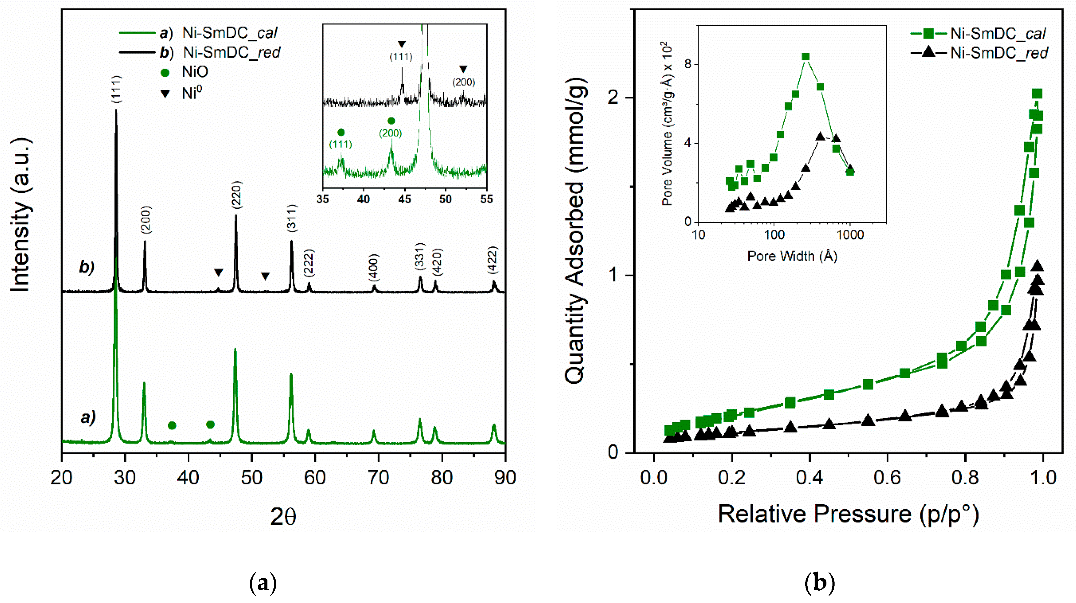
3.1. XRD and Textural Characterization of Ni-SmDC Catalyst

Figure 1a displays the X-ray diffraction patterns of Ni-SmDC powders calcined at 750 °C and after a reduction treatment in H2 up to 800 °C. The crystallite sizes calculated by Scherrer’s equation are reported in Table 1. The XRD pattern of the calcined sample shows well-defined peaks of the cubic fluorite phase of CeO2 (JCPDS 81-0792) with Fm-3m space group [34] and weak peaks of NiO cubic phase (JCPDS 78-0643). No trace of Sm2O3 oxide cubic phase was revealed, confirming that Sm forms a Ce0.85Sm0.15O2-δ solid solution ascribable to the good dispersion of Ce3+ and Sm3+ cations’ precursors during the synthetic procedure. The NiO low-intensity peaks at 37.3° and 43.3° were due to the low NiO content, but also to the fact that a limited part of Ni2+ ions were included into the cubic fluorite structure of the Ce0.85Sm0.15O2-δ phase [29]. After reduction at 800 °C, Ce0.85Sm0.15O2-δ phase remained unchanged and no decomposition into Sm2O3-CeO2 oxides was observed. Narrow peaks and correspondingly increased crystallites’ sizes from 18 to 20 nm were detected. NiO was fully reduced to Ni0 metallic phase with cubic structure (JCPDS 87-0712). Ni0 showed narrow peaks with a 20 nm crystallite size, which was larger than that of NiO, suggesting coarsening and/or aggregation of Ni0 particles was occurring at high temperature.
Figure 1b shows the nitrogen adsorption-desorption isotherms and the pore-size distribution (PSD) of Ni-SmDC powder samples after calcination at 750 °C and after reduction at 800 °C. The textural properties are reported in Table 1. The isotherms give a qualitative assessment of the porous microstructure. The isotherms of both calcined and reduced samples exhibited a similar shape, comparable to types II and III, according to the IUPAC (International Union of Pure and Applied Chemistry) classification [35], indicating macroporous materials, with the N2 adsorption-desorption hysteresis loop of H3 type. The hysteresis loops of both samples were in the relative pressure range of 0.51–0.98 and they were characterized by slit-shaped pores formed by aggregation of plate-like particles, suggesting the presence of dominant macropores and some mesopores. The pore size distributions were determined from BJH desorption isotherm. The pore size distribution of both calcined and reduced samples was broad because the result of BJH pore-size distribution could be attributed to the total contribution of both intra- and interparticle pores. The PDS curves of both samples show a pore-width distribution in the range 2.6–100 nm. The primary pore diameter was about 26.5 nm (mesoporous) for the calcined sample and in the range between 40 and 66 nm for the reduced sample. The thermal treatment of reduction caused a significant decrease in the pore volume and a decrease of porosity due to sintering. The specific surface area of the calcined sample was 31 m2g−1, while it decreased to 15 m2g−1 after reduction at 800 °C, meaning that pore volume contraction of 50% and increasing of primary pore width occurred. The decrease of surface area and the corresponding increase of the primary pore diameter from 26.5 nm to 66 nm were in accordance with the corresponding increase of crystallite size revealed from XRD analysis and reported in Table 1.

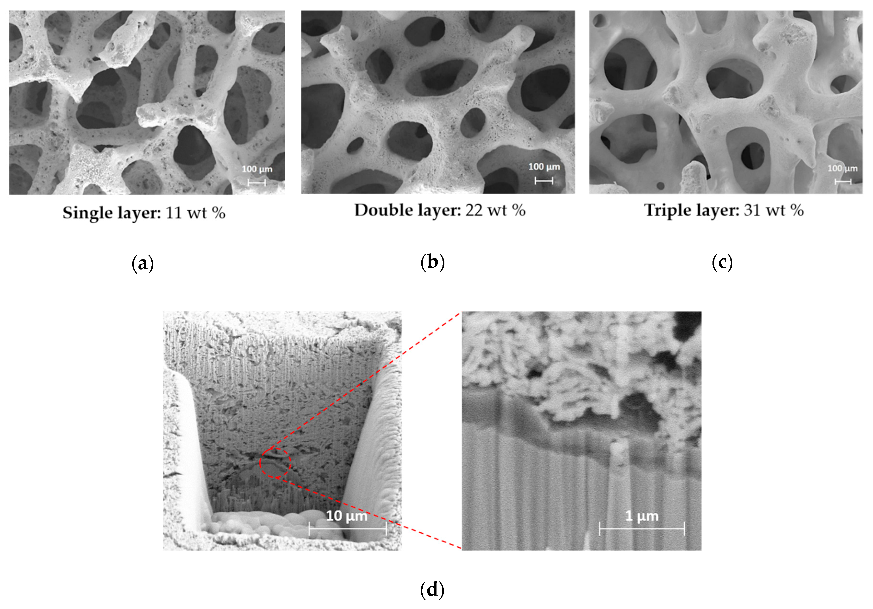
3.2. Morphological Characterization of Uncoated Foam

The microstructural characterization of NiCrAl foam was performed using SEM-EDX and FIB-SEM combined systems. The foam was pre-oxidized at high temperature and showed a passivated film on the surface that prevented the internal oxidization [36]. The oxidation behavior of Ni-Cr-Al alloys has been widely investigate [20,37,38,39,40]. Figure 2 shows the morphology of NiCrAl foam before and after using the FIB milling to expose a cross-section. The elements’ concentrations (wt.%) along the oxide/alloy depth-profile were determined by EDX spot-analysis and are reported in Table 2.
Figure 2a displays pores with size of 500 μm and a rough surface made of sintered spheres ascribable to the passivated layer. The high roughness of the oxidized layer, due to nano-scale grains grown in island patterns, increases the specific surface area and ensures a good adhesion of the catalyst coating [20,39]. Figure 2b shows irregular pyramidal-shaped crystallites of 30 ± 12 μm size and two regions in the oxide layer, one inner and one outer. EXD spot analyses (Spectrum 1 and Spectrum 2) revealed different chemical compositions of passivated layer, as reported in Table 2. From the inner (Spectrum 1) to the outer (Spectrum 2), a significant enrichment of Cr (from 26.9 to 52.3 wt.%) was revealed, while the Ni content decreased from 67.0 to 41.9 wt.%. The Ni content was large in both regions while the Al was almost constant and much lower. In agreement with literature data [41], the irregular pyramidal-shaped grains can be attributed to NiCr2O4/Cr2O3 mixed oxides, while the larger Ni content in the inner part may be related to a partial formation of NiO. Thus, NiCr2O4 spinel phase can be formed by solid-state reaction between NiO grains and Cr2O3 layer [40,42]. The presence of surface oxides is further highlighted by Figure 2c, where the oxide/metal alloy cross-section, after FIB milling and polishing steps, is shown. Two different microstructures are clearly displayed, namely, a 1.7 ± 0.3 μm-thick surface oxide layer composed of sintered grains and an underlying dense metallic matrix. A very good adhesion without pores or micro-cracks is displayed. This fact can be likely related to the uniform oxide layer grown during the pre-oxidation process. The chemical composition of the oxide/alloy cross-section was also measured by EDX spot analyses. Moving from the oxide layer (Spectrum 4) toward the metallic substrate (Spectrum 3), the chemical composition sensitively changed. Spectrum 4 revealed a pronounced enrichment of Al and Cr close to the oxide/metal interface and a severe Ni-depletion (10.6 wt.%). Conversely, an increase of Ni (up to 66.2 wt.%) and the disappearance of the oxygen content were revealed in the matrix alloy by Spectrum 3. The chemical analysis of cross-section showed that Al2O3 and Cr2O3 were developed by the internal oxidation of both aluminum and chromium in the alloy, in agreement with previous literature studies [40,43,44]. According to Giggins and Pettit [43], the simultaneous formation of an external layer of Cr2O3 and an inner protective layer of α-Al2O3 at the oxide/alloy interface is due to the diffusion of atomic oxygen and alloy constituents at high temperature. However, a small amount of pure Ni may be formed between the internal oxidation zone of α-Al2O3 and the Cr2O3 upper layer for a short oxidation time [40]. In agreement with the above discussion, the irregular interface between α-Al2O3 and metallic matrix, shown in Figure 2c, may be likely due to the internal diffusion of Al.

3.3. Morphological Characterization of Structured Catalyst

The morphology of the deposited catalyst coating layer was investigated by SEM and FIB-SEM combined system. Figure 3 shows SEM micrographs of single- (a), double- (b), and triple- (c) deposited layers of Ni-SmDC catalyst. The weight gain for each deposited layer is reported below each micrograph. Figure 3d shows the cross-section of double-deposited layer Ni-SmDC/NiCrAl structured catalyst, after FIB milling.
In Figure 3a dark spots due to uncoated or bare foam are observed, indicating that a single deposition was not enough to fully cover the surface of the metallic substrate. Figure 3b shows that the double-deposited layer homogeneously covered the metallic substrate and caused a slight decrease of the pore size. Figure 3c does not show any significant morphology improvement in comparison to Figure 3b, but it affects the porosity of the foam, reducing the pore size. Thus, the double-layer structured catalyst was chosen for the catalytic tests reported in the following. The morphology of double-deposited layer was further investigated by using the FIB-SEM cross-sectional analysis. Figure 3d shows the cross-section of Ni-SmDC/NiCrAl structured catalyst. The deposited catalyst had an average thickness of 16.9 μm and it showed a homogeneous microstructure with good porosity that facilitated the gas permeability. An enlarged view highlights three parts from the top to the bottom: The deposited porous catalyst layer, the dense passivated layer, and the metallic alloy. The dense oxide layer was about 0.33 μm thick and it displayed a good interfacial adhesion with the deposited Ni-SmDC catalyst, settling that the wash-coating method was a proper deposition technique. According to the above paragraph, the roughness of the oxidation layer and the absence of micro-cracks improved the bonding strength and the adhesion between the deposited catalyst and the NiCrAl foam, avoiding the layer peeling off.

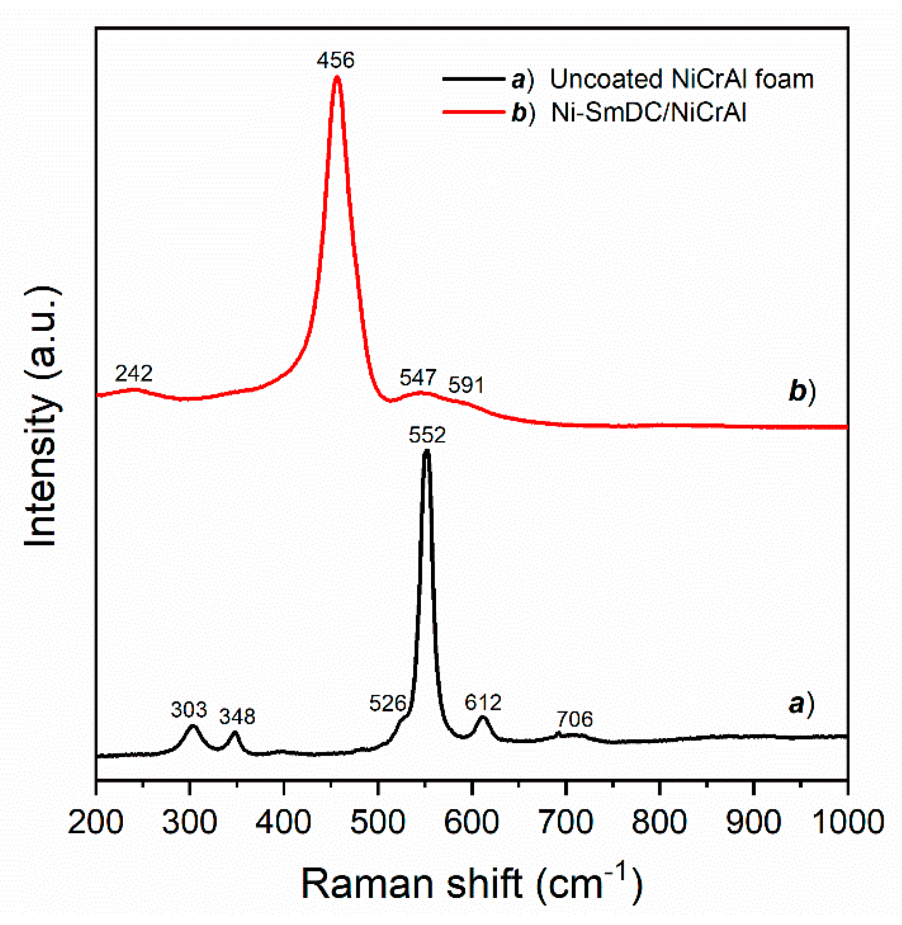
3.4. Raman Characterization

The Raman spectra of NiCrAl foam (spectrum a) and calcined Ni-SmDC/NiCrAl structured catalyst (spectrum b) are shown in Figure 4. In spectrum (a), Raman peaks at 303 cm−1 (A1g), 348 cm−1 (Eg), 552 cm−1 (A1g), and 612 cm−1 (Eg) can be assigned to the Raman modes of Cr2O3 [45,46]; besides a weak and broad peak at 706 cm−1 can be assigned to amorphous CrO2 [46]. A very weak shoulder at 526 cm−1 could be assigned to NiCr2O4 spinel structure [47], whereas there is no evidence of NiO and Al2O3. The Raman results suggest that the surface consisted mainly of chromium oxides, according to the EDX microanalysis previously reported. The Raman spectrum (b) shows a marked peak at 456 cm−1 (F2g), assigned to the Raman mode of CeO2. This peak is broadened and shifted toward lower frequency in comparison to pure ceria because of the lattice defects created by the introduction of Sm3+ dopant ions. The sample shows another weak peak at 242 cm−1 and two broad bands at 547 cm−1 (D1 band) and 591 cm−1 (D2 band), due to the oxygen defects generated by dopant ions in the lattice of ceria. Thus, Raman analysis confirmed that Sm3+ ions formed solid solution with CeO2 [29,48,49].

3.5. Temperature Programmed Reduction (H2-TPR)

The H2-TPR profiles from room temperature to 800 °C of NiCrAl foam (profile a), Ni-SmDC powder (profile b). and Ni-SmDC/NiCrAl structured catalyst (profile c) are reported in Figure 5. The corresponding H2 consumptions amounts (mmol·g−1) are reported in Table 3.
The H2-TPR profile of NiCrAl foam (profile a) shows three peaks at 372, 523, and 685 °C, due to the reduction of the passivated surface. As shown by FIB-SEM and Raman characterizations, and according to literature [39,40], the high temperature oxidation of NiCrAl alloy produces a layer of different oxides, such as α-Al2O3, Cr2O3, NiCr2O4 spinel, and trace of NiO. The weak peak at 372 °C corresponds to the hexavalent chromium reduction to Cr3+, while the narrow and more intense peak at 523 °C may be ascribed to Cr3+→ Cr2+ reduction of Cr2O3 [50,51,52] and NiCr2O4 [53]. The broad peak at 685 °C can be assigned to the reduction of Ni2+ to Ni0 of NiO interacting with Cr2O3 [54] and/or into NiCr2O4 spinel oxide [53], overlapped to Cr3+→Cr2+ reduction into the bulk [55]. The total H2 consumption of NiCrAl foam was quite small (0.11 mmol·g−1), confirming that the oxides were present only on a very thin surface layer.
The H2-TPR of Ni-SmDC powder (profile b) shows a weak peak at 285 °C, two intense and overlapped peaks at 375 and 440 °C, and a subsequent H2 consumption increase up to 800 °C. In agreement with literature [29,56,57], the weak peak at 285 °C corresponds to the reduction of O2 chemisorbed (i.e., O 2 2 ) on the vacancies formed by Sm3+ doping but also, in a small fraction, into Ni-O-Ce solid solution. The intense peaks at 375 and 440 °C correspond to the reduction of NiO particles differently interacting with the support and to the contribution of Ce4+→Ce3+ reduction of the surface grains. The final and incomplete H2 consumption was due to the diffusion-limited reduction of bulk Ce4+ [58]. The experimental hydrogen consumption was 1.33 mmol g−1. This value was larger than the hydrogen amount for Ni2+→Ni0 reduction 0.78 mmol g−1; thus, the excess of hydrogen consumption corresponded to the 18.2% of Ce4+→Ce3+ reduction.
The TPR profile of Ni-SmDC/NiCrAl structured catalyst (profile c) is an overlapping of profiles (a) and (b), corresponding to the reduction of NiCrAl foam and Ni-SmDC catalyst. The peak at 326 °C can be assigned to the reduction of chemisorbed oxygen species and Ni2+ ions incorporated into the ceria lattice of the Ni-SmDC, superimposed to the initial Cr6+→Cr3+ reduction of Cr2O3 formed on the surface of NiCrAl alloy. Well-defined peaks at 388 and 455 °C were due to the reduction of NiO particles with weak and strong interaction with the Ce0.85Sm0.15O2-δ support, overlapped to the complete Cr6+→Cr3+ reduction. The reduction peak at 566 °C and the shoulder at 635 °C can be attributed to the Cr3+→Cr2+ reduction and to the reduction of a fraction of bulk Ce4+ of Ni-SmDC layer interacting with the foam [59]. The peak at 721 °C corresponds to the Ni2+→Ni0 and Cr3+→Cr2+ reductions of the oxide species on the foam surface together with partial Ce4+→Ce3+ bulk reduction of Ce0.85Sm0.15O2-δ support. The hydrogen consumption of Ni-SmDC/NiCrAl structured catalyst was 0.36 mmol g−1, larger than that obtained for bare NiCrAl foam. Because the coating layer was the 22 wt.% of the structured catalyst, the hydrogen consumption normalized for the Ni-SmDC amount was 1.20 mmol g−1 that is in very good agreement with experimental value for Ni-SmDC powder.
Finally, after a reduction in H2 up to 800 °C, TPR measurements showed that (1) the thin passivated layer on the surface of metallic foam was reduced and CrO and Ni0 species were formed, (2) Ni supported on SmDC powder was completely reduced to Ni0, and (3) the redox properties of Ni-SmDC catalyst did not significantly change after the deposition on the foam.

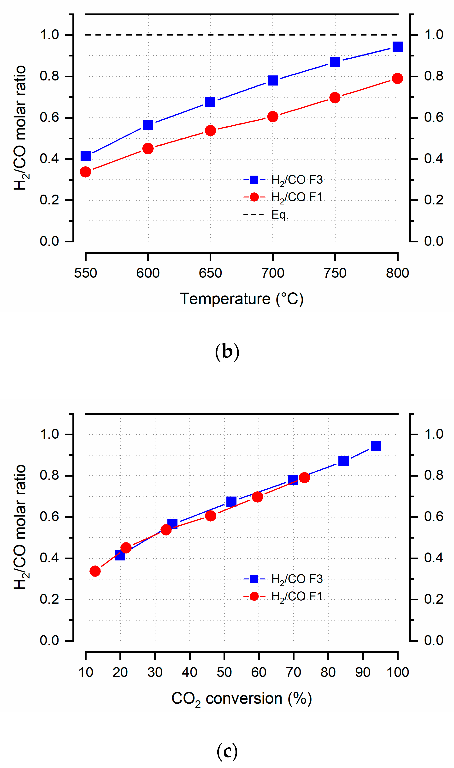
3.6. Catalytic Activity

The catalytic test of dry reforming of methane (DRM) was carried out in a fixed-bed quartz reactor using a single and a triple catalytic bed as schematically reported in Figure 6a. The single and triple configurations are named F1 and F3, respectively. The images of F1 and F3 structured catalysts are displayed in Figure 6b. A double layer Ni-SmDC/NiCrAl structured catalyst was chosen for the catalytic tests. The dry reforming of methane reaction was investigated at the pressure of 1.3 bar and in transient conditions of temperature in the range of 800–550 °C, each 50 °C. A flow of reactants (100 cm3·min−1) having the composition CH4:CO2:N2:He = 20:20:10:50 (vol %) was fed into the reactor with a gas hourly space velocity (GHSV) of 94,000 h−1 for F1 and 31,000 h−1 related for F3. A preliminary investigation (not reported) showed that the uncoated foam was not catalytically active under the present experimental conditions.
The effect of GHSV and reaction temperature on the catalytic activity of F1 and F3 are discussed. Figure 7 shows the CH4 and CO2 conversion (%) as a function of temperature (a), the corresponding H2/CO molar ratio vs. temperature (b) and the H2/CO molar ratio as a function of CO2 conversion (%) (c). The reaction conditions are: CH4/CO2 = 1, P = 1.3 bar, GHSV = 94,000 h−1 for F1, GHSV = 31,000 h−1 for F3. The equilibrium conversion curves are also added as dashed lines. As expected by the strong endothermicity of the DRM reaction, the reactants’ conversions were promoted by increasing temperature (Figure 7a). The GHSV of F1 (94,000 h−1) was significantly high and the CH4 conversion was quite low going from 6% at 550 °C to 59% at 800 °C, which is well below the thermodynamic value (93% at 800 °C). Moreover, at all investigated temperatures, the CO2 conversion was much higher than that of CH4, reaching a maximum of 73% at 800 °C. As already reported in literature [29,60,61], if the mass transfer limitation effect is negligible, the DRM is better promoted at low GHSV. Indeed, using three structured catalysts (F3), the GHSV decreased to 31,000 h−1 and the CH4 conversion markedly increased going from 10% at 550 °C to a maximum of 87% at 800 °C, much closer to the equilibrium dashed line. Correspondingly, the conversion of CO2 was favored over that of CH4 but the difference between CO2 and CH4 was reduced by increasing temperature. At 800 °C, the CO2 conversion was 94%, corresponding to the thermodynamic value. The always greater CO2 conversion, compared to CH4, was due to the concomitant occurrence of the RWGS reaction Equation (2). Thus, the not-reformed CO2 was hydrogenated by the produced H2, forming CO and H2O and causing an H2/CO molar ratio less than unity in the whole temperature range, as shown in Figure 7b.
The H2/CO ratio increased towards the thermodynamic value by increasing the temperature and decreasing the GHSV, in agreement with the decreasing difference between CO2 and CH4 conversion values of the F3 system compared to F1. Furthermore, as shown in Figure 7c, the H2/CO ratio increased linearly with the CO2 conversion, independently from the GHSV, confirming that the RWGS was kinetically favored over the DRM and close to thermodynamic equilibrium.
Figure 8 shows the Arrhenius plot of the reactants’ consumption rates for the F1 structured catalyst. The natural logarithm of the consumption rates linearly depends on the inverse of temperature 1 T between 550 and 700 °C, confirming that the reaction operates in a kinetic regime and, in agreement with the above discussion, the CO2 consumption rates are always greater than those of CH4. The corresponding apparent activation energies, proportional to the slope of the straight lines, were equal to ECO2 = 64.8 kJ mol−1 and ECH4 = 79.3 kJ mol−1, respectively. These values were in good agreement with those previously obtained for the Ni-SmDC powder [29], suggesting that the coating process over the NiCrAl foam did not significantly alter the kinetics of the DRM reaction.
To verify the integration of the structured catalyst in IIR-SOFC configuration, the F3 catalytic system was studied in four daily start-up and shut-down operation (DSS) operations. According to the literature, in such condition a quick damage of the reforming system may occur [62,63]. The temperatures examined between 550 and 800 °C lasted a total of 20 h. The CH4 and CO2 conversion and the H2/CO ratio are shown in Figure S2, and the values at the representative temperatures of 700, 750, and 800 °C are reported in Table 4. The F3 system was particularly stable at all investigated temperatures and a decrease in performance was not observed. On the contrary, conversions and the H2/CO ratio tended to increase; for example, at the low temperature of 700 °C the CH4 conversion increased from 55.2% up to 63.4%.
The main reason for the catalyst deactivation during DRM is recognized in the loss of Ni active sites due to carbon deposition [8,64,65], especially during low temperature operation [66,67]. Therefore, a morphologic analysis of spent catalysts was performed to investigate the eventual carbon formation. SEM micrographs of the three portions of F3 used catalyst, named F3inlet, F3medium, and F3outlet, are reported in Figure 9. For each portion, high (on the top) and low (on the bottom), magnification images are displayed. The high magnification micrographs reveal the presence of deposited carbon filaments and the low magnification images show cracks on the Ni-SmDC coating layer distributed all over the porous structured foam. From F3inlet to F3outlet the amount and thickness of carbon filament decreased, and the number of cracks was also reduced. Specifically, the carbon content measured by EDX analysis dropped from 17, 14, and 2 wt.% from the F3inlet, F3medium, and F3outlet portions, respectively.
This feature was likely due to the higher methane partial pressure and the lower operating temperatures at the inlet of the catalytic bed in comparison to the outlet [68]. Thus, in the inlet portion of the catalyst (F3inlet), the side reactions were most favored, causing more carbon formation, cracks, and few detachments as well.
Figure 10 shows SEM micrographs cross-section, as a result of FIB milling, of F3inlet after DRM reaction. The SEM cross-section analysis allowed us to investigate the presence of carbon in the inner part of the catalytic layer and verify the origin of carbon formation. The analysis was focused on the cracks of the coating catalyst (Figure 10a), where the formation of carbon was mostly evident. Figure 10b shows the presence of carbon nanotubes through the whole thickness of the coating layer and Figure 10c displays the presence of carbon filaments even at the interface between the oxide layer and the alloy.
The reducing atmosphere necessary for the activation of the catalytic system, as evidenced by the TPR analysis and during the DRM, where a high concentration of H2/CO is present, favors the formation of Ni particles on the surface of the foam, although it cannot be excluded that some of them may be attacked by the internal Ni-SmDC layer, which strongly interacts with the foam. Despite the considerable formation of carbon nanotubes, the catalytic activity did not decrease, probably because they did not completely cover the catalytically active Ni particles. However, they damaged the overall structure, preventing a possible reactivation of the structured catalyst. This observation was in agreement with other authors [14], who have studied Al2O3-coated on Ni-foam. During the DRM they showed carbon residues originating in the interface between Ni particles strongly interacting with the Al2O3 layers, but not on the bare Ni-foam.

4. Conclusions

Ni-SmDC/NiCrAl structured catalyst for DRM was designed as a biogas pre-reformer for IIR-SOFCs. The characteristic morphology and the roughness of the passivated NiCrAl foam ensured a good adhesion between the Ni-SmDC coating catalyst and the metallic foam. The DRM catalytic tests performed in a fixed-bed quartz reactor with a single (F1) and triple (F3) catalytic bed showed that a single-structured catalyst with a corresponding high GHSV (94,000 h−1) showed a CH4 conversion of 60% at 850 °C. Thus, it can be employed as pre-reformer at temperatures as high as 850 °C (or above) that are typical of electrolyte supported SOFCs. Otherwise a triple-structured catalyst with a lower GHSV (31,000 h−1) can be used for intermediate temperature (IT)-SOFCs operating in the range 650–750 °C. Indeed, the F3 catalyst showed a CH4 conversion of 60% at 700 °C, which is suitable for the indirect internal reforming of biogas. Finally, the morphologic analysis of spent catalysts revealed some cracks on the surface and carbon filaments through the whole thickness of the catalyst mainly on the inlet portion of the catalyst. Thus, to minimize the carbon formation, further work is in progress to develop a structured catalyst with a graded catalyst composition.

Supplementary Materials

The following are available online at https://www.mdpi.com/2076-3417/10/9/3083/s1, Figure S1. Daily start-up and shut-down operation (DSS). Figure S2. (a) CH4 and (b) CO2 conversion (%) as a function of temperature, (c) the corresponding H2/CO molar ratio, for the four catalytic runs. Reaction conditions: CH4/CO2 = 1; P = 1.3 bar; GHSV = 31000 h−1 (F3).

Author Contributions

Conceptualization, I.L. and E.D.B.; methodology, M.S.; investigation, M.S., I.L., and A.N.; data curation, A.N. and C.R.; writing—original draft preparation, M.S., I.L., S.T., and E.D.B.; writing—review and editing, M.S., I.L., S.T., and E.D.B.; visualization, S.L.; project administration, E.D.B.; funding acquisition, E.D.B. All authors have read and agreed to the published version of the manuscript.

Funding

This research was funded by the Italian Ministry for Education, University and Research MiUR grant number PRIN- 2017-Prot.2017FCFYHK_004.

Conflicts of Interest

The authors declare no conflict of interest.

References

  1. Abdulrasheed, A.; Jalil, A.A.; Gambo, Y.; Ibrahim, M.; Hambali, H.U.; Shahul Hamid, M.Y. A Review on Catalyst Development for Dry Reforming of Methane to Syngas: Recent Advances. Renew. Sustain. Energy Rev. 2019, 108, 175–193. [Google Scholar] [CrossRef]
  2. Jang, W.J.; Shim, J.O.; Kim, H.M.; Yoo, S.Y.; Roh, H.S. A Review on Dry Reforming of Methane in Aspect of Catalytic Properties. Catal. Today 2019, 324, 15–26. [Google Scholar] [CrossRef]
  3. Zhang, G.; Liu, J.; Xu, Y.; Sun, Y. A Review of CH4–CO2 Reforming to Synthesis Gas over Ni-Based Catalysts in Recent Years (2010–2017). Int. J. Hydrogen Energy 2018, 43, 15030–15054. [Google Scholar] [CrossRef]
  4. Aramouni, N.A.K.; Touma, J.G.; Tarboush, B.A.; Zeaiter, J.; Ahmad, M.N. Catalyst Design for Dry Reforming of Methane: Analysis Review. Renew. Sustain. Energy Rev. 2018, 82, 2570–2585. [Google Scholar] [CrossRef]
  5. Lanzini, A.; Leone, P.; Guerra, C.; Smeacetto, F.; Brandon, N.P.; Santarelli, M. Durability of Anode Supported Solid Oxides Fuel Cells (SOFC) under Direct Dry-Reforming of Methane. Chem. Eng. J. 2013, 220, 254–263. [Google Scholar] [CrossRef]
  6. Shiratori, Y.; Ijichi, T.; Oshima, T.; Sasaki, K. Internal Reforming SOFC Running on Biogas. Int. J. Hydrogen Energy 2010, 35, 7905–7912. [Google Scholar] [CrossRef]
  7. Lo Faro, M.; Antonucci, V.; Antonucci, P.L.; Aricó, A.S. Fuel Flexibility: A Key Challenge for SOFC Technology. Fuel 2012, 102, 554–559. [Google Scholar] [CrossRef]
  8. Luisetto, I.; Tuti, S.; Battocchio, C.; Lo Mastro, S.; Sodo, A. Ni Supported on γ-Al2O3 Promoted by Ru for the Dry Reforming of Methane in Packed and Monolithic Reactors. Fuel Process. Technol. 2017, 158, 130–140. [Google Scholar] [CrossRef]
  9. Sarno, C.; Luisetto, I.; Zurlo, F.; Licoccia, S.; Di Bartolomeo, E. Lanthanum Chromite Based Composite Anodes for Dry Reforming of Methane. Int. J. Hydrogen Energy 2018, 43, 14742–14750. [Google Scholar] [CrossRef]
  10. Klein, J.M.; Bultel, Y.; Georges, S.; Pons, M. Modeling of a SOFC Fuelled by Methane: From Direct Internal Reforming to Gradual Internal Reforming. Chem. Eng. Sci. 2007, 62, 1636–1649. [Google Scholar] [CrossRef]
  11. Balzarotti, R.; Italiano, C.; Pino, L.; Cristiani, C.; Vita, A. Ni/CeO2-Thin Ceramic Layer Depositions on Ceramic Monoliths for Syngas Production by Oxy Steam Reforming of Biogas. Fuel Process. Technol. 2016, 149, 40–48. [Google Scholar] [CrossRef]
  12. Chai, R.; Fan, S.; Zhang, Z.; Chen, P.; Zhao, G.; Liu, Y.; Lu, Y. Free-Standing NiO-MgO-Al2O3 Nanosheets Derived from Layered Double Hydroxides Grown onto FeCrAl-Fiber as Structured Catalysts for Dry Reforming of Methane. ACS Sustain. Chem. Eng. 2017, 5, 4517–4522. [Google Scholar] [CrossRef]
  13. Fukuhara, C.; Hyodo, R.; Yamamoto, K.; Masuda, K.; Watanabe, R. A Novel Nickel-Based Catalyst for Methane Dry Reforming: A Metal Honeycomb-Type Catalyst Prepared by Sol-Gel Method and Electroless Plating. Appl. Catal. A Gen. 2013, 468, 18–25. [Google Scholar] [CrossRef]
  14. Pegios, N.; Schroer, G.; Rahimi, K.; Palkovits, R.; Simeonov, K. Design of Modular Ni-Foam Based Catalysts for Dry Reforming of Methane. Catal. Sci. Technol. 2016, 6, 6372–6380. [Google Scholar] [CrossRef]
  15. Sadykov, V.; Mezentseva, N.; Fedorova, Y.; Lukashevich, A.; Pelipenko, V.; Kuzmin, V.; Simonov, M.; Ishchenko, A.; Vostrikov, Z.; Bobrova, L.; et al. Structured Catalysts for Steam/Autothermal Reforming of Biofuels on Heat-Conducting Substrates: Design and Performance. Catal. Today 2015, 251, 19–27. [Google Scholar] [CrossRef]
  16. Benito, P.; Monti, M.; Bersani, I.; Basile, F.; Fornasari, G.; Scavetta, E.; Tonelli, D.; Vaccari, A. Coating of FeCrAlloy Foam with Rh Catalysts: Optimization of Electrosynthesis Parameters and Catalyst Composition. Catal. Today 2012, 197, 162–169. [Google Scholar] [CrossRef]
  17. Yanxia, L.; Chaoming, L.; Zhongliang, L.; Lixia, S. Catalytic Combustion of CH4/Air Mixtures over Metal Foam Monoliths. Phys. Procedia 2015, 66, 249–252. [Google Scholar] [CrossRef] [Green Version]
  18. Sinn, C.; Pesch, G.R.; Thöming, J.; Kiewidt, L. Coupled Conjugate Heat Transfer and Heat Production in Open-Cell Ceramic Foams Investigated Using CFD. Int. J. Heat Mass Transf. 2019, 139, 600–612. [Google Scholar] [CrossRef]
  19. Kim, S.; Lee, C.-W. A Review on Manufacturing and Application of Open-Cell Metal Foam. Procedia Mater. Sci. 2014, 4, 305–309. [Google Scholar] [CrossRef]
  20. Walther, G.; Klöden, B.; Büttner, T.; Weissgärber, T.; Kieback, B.; Böhm, A.; Naumann, D.; Soberi, S.; Timberg, L. A New Class of High Temperature and Corrosion Resistant Nickel-Based Open-Cell Foams. Adv. Eng. Mater. 2008, 10, 803–811. [Google Scholar] [CrossRef]
  21. Ho, P.H.; De Nolf, W.; Ospitali, F.; Beton, D.; Torkuhl, L.; Fornasari, G.; Vaccari, A.; Benito, P. Insights into Coated NiCrAl Open-Cell Foams for the Catalytic Partial Oxidation of CH4. React. Chem. Eng. 2019, 4, 1768–1778. [Google Scholar] [CrossRef]
  22. Meille, V. Review on Methods to Deposit Catalysts on Structured Surfaces. Appl. Catal. A Gen. 2006, 315, 1–17. [Google Scholar] [CrossRef]
  23. Montebelli, A.; Visconti, C.G.; Groppi, G.; Tronconi, E.; Cristiani, C.; Ferreira, C.; Kohler, S. Methods for the Catalytic Activation of Metallic Structured Substrates. Catal. Sci. Technol. 2014, 4, 2846–2870. [Google Scholar] [CrossRef]
  24. Kambolis, A.; Matralis, H.; Trovarelli, A.; Papadopoulou, C. Ni/CeO2-ZrO2 Catalysts for the Dry Reforming of Methane. Appl. Catal. A Gen. 2010, 377, 16–26. [Google Scholar] [CrossRef]
  25. Luisetto, I.; Tuti, S.; Di Bartolomeo, E. Co and Ni Supported on CeO2 as Selective Bimetallic Catalyst for Dry Reforming of Methane. Int. J. Hydrogen Energy 2012, 37, 15992–15999. [Google Scholar] [CrossRef]
  26. Düdder, H.; Kähler, K.; Krause, B.; Mette, K.; Kühl, S.; Behrens, M.; Scherer, V.; Muhler, M. The Role of Carbonaceous Deposits in the Activity and Stability of Ni-Based Catalysts Applied in the Dry Reforming of Methane. Catal. Sci. Technol. 2014, 4, 3317–3328. [Google Scholar] [CrossRef] [Green Version]
  27. Damyanova, S.; Pawelec, B.; Arishtirova, K.; Fierro, J.L.G. Ni-Based Catalysts for Reforming of Methane with CO2. Int. J. Hydrogen Energy 2012, 37, 15966–15975. [Google Scholar] [CrossRef]
  28. Jiang, S.P.; Ye, Y.; He, T.; Ho, S.B. Nanostructured Palladium-La0.75Sr0.25Cr0.5Mn0.5O3/Y2O3-ZrO2 Composite Anodes for Direct Methane and Ethanol Solid Oxide Fuel Cells. J. Power Sources 2008, 185, 179–182. [Google Scholar] [CrossRef]
  29. Luisetto, I.; Tuti, S.; Romano, C.; Boaro, M.; Di Bartolomeo, E. Dry Reforming of Methane over Ni Supported on Doped CeO2: New Insight on the Role of Dopants for CO2 Activation. J. CO2 Util. 2019, 30, 63–78. [Google Scholar] [CrossRef]
  30. Akri, M.; Pronier, S.; Chafik, T.; Achak, O.; Granger, P.; Simon, P.; Trentesaux, M.; Batiot-Dupeyrat, C. Development of Nickel Supported La and Ce-Natural Illite Clay for Autothermal Dry Reforming of Methane: Toward a Better Resistance to Deactivation. Appl. Catal. B Environ. 2017, 205, 519–531. [Google Scholar] [CrossRef]
  31. Vasiliades, M.A.; Makri, M.M.; Djinović, P.; Erjavec, B.; Pintar, A.; Efstathiou, A.M. Dry Reforming of Methane over 5 Wt% Ni/Ce1-XPrxO2-δ Catalysts: Performance and Characterisation of Active and Inactive Carbon by Transient Isotopic Techniques. Appl. Catal. B Environ. 2016, 197, 168–183. [Google Scholar] [CrossRef]
  32. Vasiliades, M.A.; Djinović, P.; Davlyatova, L.F.; Pintar, A.; Efstathiou, A.M. Origin and Reactivity of Active and Inactive Carbon Formed during DRM over Ni/Ce0.38Zr0.62O2-δ Studied by Transient Isotopic Techniques. Catal. Today 2018, 299, 201–211. [Google Scholar] [CrossRef]
  33. Vasiliades, M.A.; Damaskinos, C.M.; Kyprianou, K.K.; Kollia, M.; Efstathiou, A.M. The Effect of Pt on the Carbon Pathways in the Dry Reforming of Methane over Ni-Pt/Ce0.8Pr0.2O2-δ Catalyst. Catal. Today 2019. [Google Scholar] [CrossRef]
  34. Liu, B.; Liu, R.; Li, Q.J.; Yao, M.G.; Zou, B.; Cui, T.; Liu, B.B.; Liu, J. Study of High Pressure Structural Stability of CeO2 Nanoparticles. Chin. Phys. C 2013, 37. [Google Scholar] [CrossRef] [Green Version]
  35. Sing, K.S.W.; Everett, D.H.; Haul, R.A.W. Provisional international union of pure and applied chemistry commission on colloid and surface chemistry subcommittee on reporting gas adsorption data * Reporting physisorption data for gas/solid systems with Special Reference to the Determination of Surface Area and Porosity. Pure Appl. Chem. 1985, 57, 603–619. [Google Scholar]
  36. Kim, D.H.; Yu, B.Y.; Cha, P.R.; Yoon, W.Y.; Byun, J.Y.; Kim, S.H. A Study on FeCrAl Foam as Effective Catalyst Support under Thermal and Mechanical Stresses. Surf. Coat. Technol. 2012, 209, 169–176. [Google Scholar] [CrossRef]
  37. Kvernes, I.A.; Kofstad, P. The Oxidation Behavior of Some Ni-Cr-Al Alloys at High Temperatures. Metall. Trans. 1972, 3, 1511–1519. [Google Scholar] [CrossRef]
  38. Seraffon, M.; Simms, N.J.; Sumner, J.; Nicholls, J.R. Oxidation Behaviour of NiCrAl and NiCoCrAl Bond Coatings under Industrial Gas Turbine Conditions. Oxid. Met. 2014, 81, 203–215. [Google Scholar] [CrossRef]
  39. Kim, H.G.; Lim, S.H. Microstructural Characterization of Oxide Layers Formed on Ni–20Cr–8Al Alloy Foam Using Transmission Electron Microscopy. Surf. Interface Anal. 2017, 49, 880–884. [Google Scholar] [CrossRef]
  40. Nijdam, T.J.; Jeurgens, L.P.H.; Sloof, W.G. Promoting Exclusive α-Al2O3 Growth upon High-Temperature Oxidation of NiCrAl Alloys: Experiment versus Model Predictions. Acta Mater. 2005, 53, 1643–1653. [Google Scholar] [CrossRef]
  41. Ptak, M.; Maczka, M.; G, A.; Pikul, A.; Macalik, L.; Hanuza, J. Temperature-Dependent XRD, IR, Magnetic, SEM and TEM Studies of Jahn–Teller Distorted NiCr2O4 Powders. J. Solid State Chem. 2013, 201, 270–279. [Google Scholar] [CrossRef]
  42. Nijdam, T.J.; Van Der Pers, N.M.; Sloof, W.G. Oxide Phase Development upon High Temperature Oxidation of γ-NiCrAl Alloys. Mater. Corros. 2006, 57, 269–275. [Google Scholar] [CrossRef]
  43. Giggins, C.S.; Pettit, F.S. Oxidation of Ni-Cr-Al Alloys Between 1000 ° and 1200 °C. J. Electrochem. Soc. 1971, 118, 1782. [Google Scholar] [CrossRef]
  44. Guan, S.W.; Smeltzer, W.W. Oxygen Solubility and a Criterion for the Transition from Internal to External Oxidation of Ternary Alloys. Oxid. Met. 1994, 42, 375–391. [Google Scholar] [CrossRef]
  45. Shim, S.-H.; Duffy, T.S.; Jeanloz, R.; Yoo, C.-S.; Iota, V. Raman Spectroscopy and X-Ray Diffraction of Phase Transitions in Cr2O3 to 61 GPa. Phys. Rev. B Condens. Matter Mater. Phys. 2004, 69, 1–12. [Google Scholar] [CrossRef] [Green Version]
  46. Mohammadtaheri, M.; Yang, Q.; Li, Y.; Corona-Gomez, J. The Effect of Deposition Parameters on the Structure and Mechanical Properties of Chromium Oxide Coatings Deposited by Reactive Magnetron Sputtering. Coatings 2018, 8, 111. [Google Scholar] [CrossRef] [Green Version]
  47. Wang, Z.; Saxena, S.K.; Lazor, P.; O’Neill, H.S.C. An in Situ Raman Spectroscopic Study of Pressure Induced Dissociation of Spinel NiCr2O4. J. Phys. Chem. Solids 2003, 64, 425–431. [Google Scholar] [CrossRef]
  48. Li, L.; Chen, F.; Lu, J.Q.; Luo, M.F. Study of Defect Sites in Ce1-Xmxo2-δ (x = 0.2) Solid Solutions Using Raman Spectroscopy. J. Phys. Chem. A 2011, 115, 7972–7977. [Google Scholar] [CrossRef]
  49. Polychronopoulou, K.; Zedan, A.F.; AlKetbi, M.; Stephen, S.; Ather, M.; Katsiotis, M.S.; Arvanitidis, J.; Christofilos, D.; Isakovic, A.F.; AlHassan, S. Tailoring the Efficiency of an Active Catalyst for CO Abatement through Oxidation Reaction: The Case Study of Samarium-Doped Ceria. J. Environ. Chem. Eng. 2018, 6, 266–280. [Google Scholar] [CrossRef]
  50. Storaro, L.; Ganzerla, R.; Lenarda, M.; Zanoni, R.; Jiménez López, A.; Olivera-Pastor, P.; Rodríguez Castellón, E. Catalytic Behavior of Chromia and Chromium-Doped Alumina Pillared Clay Materials for the Vapor Phase Deep Oxidation of Chlorinated Hydrocarbons. J. Mol. Catal. A Chem. 1997, 115, 329–338. [Google Scholar] [CrossRef]
  51. Hari Krishna Charan, P.; Ranga Rao, G. Investigation of Chromium Oxide Clusters Grafted on SBA-15 Using Cr-Polycation Sol. J. Porous Mater. 2013, 20, 81–94. [Google Scholar] [CrossRef]
  52. Ilieva, L.I.; Andreeva, D.H. Investigation of the Chromium Oxide System by Means of Temperature-Programmed Reduction. Thermochim. Acta 1995, 265, 223–231. [Google Scholar] [CrossRef]
  53. Wang, J.; Yang, G.; Cheng, L.; Shin, E.W.; Men, Y. Three-Dimensionally Ordered Macroporous Spinel-Type MCr2O4 (M = Co, Ni, Zn, Mn) Catalysts with Highly Enhanced Catalytic Performance for Soot Combustion. Catal. Sci. Technol. 2015, 5, 4594–4601. [Google Scholar] [CrossRef]
  54. Luo, J.W.; Song, J.D.; Jia, W.Z.; Pu, Z.Y.; Lu, J.Q.; Luo, M.F. Catalytic Dehydrofluorination of 1,1,1,3,3-Pentafluoropropane to 1,3,3,3-Tetrafluoropropene over Fluorinated NiO/Cr2O3 Catalysts. Appl. Surf. Sci. 2018, 433, 904–913. [Google Scholar] [CrossRef]
  55. Wu, Z.; Deng, J.; Xie, S.; Yang, H.; Zhao, X.; Zhang, K.; Lin, H.; Dai, H.; Guo, G. Mesoporous Cr2O3-Supported Au-Pd Nanoparticles: High-Performance Catalysts for the Oxidation of Toluene. Microporous Mesoporous Mater. 2016, 224, 311–322. [Google Scholar] [CrossRef]
  56. Vita, A.; Italiano, C.; Fabiano, C.; Laganà, M.; Pino, L. Influence of Ce-Precursor and Fuel on Structure and Catalytic Activity of Combustion Synthesized Ni/CeO2 Catalysts for Biogas Oxidative Steam Reforming. Mater. Chem. Phys. 2015, 163, 337–347. [Google Scholar] [CrossRef]
  57. Tang, C.; Li, J.; Yao, X.; Sun, J.; Cao, Y.; Zhang, L.; Gao, F.; Deng, Y.; Dong, L. Mesoporous NiO-CeO2 Catalysts for CO Oxidation: Nickel Content Effect and Mechanism Aspect. Appl. Catal. A Gen. 2015, 494, 77–86. [Google Scholar] [CrossRef]
  58. Giordano, F.; Trovarelli, A.; De Leitenburg, C.; Giona, M. A Model for the Temperature-Programmed Reduction of Low and High Surface Area Ceria. J. Catal. 2000, 193, 273–282. [Google Scholar] [CrossRef]
  59. Yang, P.; Meng, Z.; Yang, S.; Shi, Z.; Zhou, R. Highly Active Behaviors of CeO2-CrOx Mixed Oxide Catalysts in Deep Oxidation of 1,2-Dichloroethane. J. Mol. Catal. A Chem. 2014, 393, 75–83. [Google Scholar] [CrossRef]
  60. Seo, M.; Kim, S.Y.; Kim, Y.D.; Park, E.D.; Uhm, S. Highly Stable Barium Zirconate Supported Nickel Oxide Catalyst for Dry Reforming of Methane: From Powders toward Shaped Catalysts. Int. J. Hydrogen Energy 2018, 43, 11355–11362. [Google Scholar] [CrossRef]
  61. Wei, J.; Iglesia, E. Isotopic and Kinetic Assessment of the Mechanism of Reactions of CH4 with CO2 or H2O to Form Synthesis Gas and Carbon on Nickel Catalysts. J. Catal. 2004, 224, 370–383. [Google Scholar] [CrossRef]
  62. Zhou, L.; Guo, Y.; Sakurai, M.; Kameyama, H. Study of Porous Anodic Alumina Supported Plate-Type Catalysts during Daily Start-up and Shut-down Operation of Methane Steam Reforming. Appl. Catal. A Gen. 2009, 364, 101–107. [Google Scholar] [CrossRef]
  63. Li, D.; Atake, I.; Shishido, T.; Oumi, Y.; Sano, T.; Takehira, K. Self-Regenerative Activity of Ni/Mg(Al)O Catalysts with Trace Ru during Daily Start-up and Shut-down Operation of CH4 Steam Reforming. J. Catal. 2007, 250, 299–312. [Google Scholar] [CrossRef]
  64. Arora, S.; Prasad, R. An Overview on Dry Reforming of Methane: Strategies to Reduce Carbonaceous Deactivation of Catalysts. RSC Adv. 2016, 6, 108668–108688. [Google Scholar] [CrossRef]
  65. Chai, Y.; Fu, Y.; Feng, H.; Kong, W.; Yuan, C.; Pan, B.; Zhang, J.; Sun, Y. A Nickel-Based Perovskite Catalyst with a Bimodal Size Distribution of Nickel Particles for Dry Reforming of Methane. ChemCatChem 2018, 10, 2078–2086. [Google Scholar] [CrossRef]
  66. Sokolov, S.; Kondratenko, E.V.; Pohl, M.M.; Barkschat, A.; Rodemerck, U. Stable Low-Temperature Dry Reforming of Methane over Mesoporous La 2O3-ZrO2 Supported Ni Catalyst. Appl. Catal. B Environ. 2012, 113–114, 19–30. [Google Scholar] [CrossRef]
  67. Luisetto, I.; Tuti, S.; Battocchio, C.; Lo Mastro, S.; Sodo, A. Ni/CeO2-Al2O3 Catalysts for the Dry Reforming of Methane: The Effect of CeAlO3 Content and Nickel Crystallite Size on Catalytic Activity and Coke Resistance. Appl. Catal. A Gen. 2015, 500, 12–22. [Google Scholar] [CrossRef]
  68. Leimert, J.; Karl, J.; Dillig, M. Dry Reforming of Methane Using a Nickel Membrane Reactor. Processes 2017, 5, 82. [Google Scholar] [CrossRef] [Green Version]
Figure 1. (a) XRD patterns and (b) N2 adsorption/desorption isotherms and pore-width distribution of Ni-SmDC samples after calcination and after reduction treatment at 800 °C.
Applsci 10 03083 g001
Figure 2. SEM micrographs of NiCrAl alloy foam (a) at low, (b) high magnification, (c) and after FIB (focused ion beam) milling.
Applsci 10 03083 g002
Figure 3. SEM micrographs of structured catalysts coated with (a) single-layer, (b) double-layer (c) and triple-layer. (d) Cross-section SEM micrography of double-layer coated Ni-SmDC/NiCrAl after FIB milling, an enlargement is displayed in the dashed red circle.
Applsci 10 03083 g003
Figure 4. Raman spectra of (a) NiCrAl foam and (b) Ni-SmDC/NiCrAl structured catalyst.
Applsci 10 03083 g004
Figure 5. Temperature programmed reduction (TPR-H2) profiles: (a) NiCrAl foam, (b) Ni-SmDC powder, (c) Ni-SmDC/NiCrAl structured catalyst.
Applsci 10 03083 g005
Figure 6. (a) Scheme of reactor loading in a single and triple catalytic bed (b) and images of single and triple portion of the structured catalyst Ni-SmDC/NiCrAl, named as F1 (above) and F3 (below).
Applsci 10 03083 g006
Figure 7. (a) CH4 and CO2 conversion (%) as a function of temperature, (b) the corresponding H2/CO molar ratio, (c) H2/CO molar ratio as a function of CO2 conversion (%). Reaction conditions: CH4/CO2 = 1, P = 1.3 bar, GHSV = 94,000 h−1 (F1), GHSV = 31,000 h−1 (F3). Equilibrium conversion is also indicated with the dashed line.
Applsci 10 03083 g007aApplsci 10 03083 g007b
Figure 8. Arrhenius plots of CH4 (closed symbol) and CO2 (open symbol) consumption rate in F1.
Applsci 10 03083 g008
Figure 9. SEM micrographs of the three portions of F3 catalyst: F3inlet, F3medium, and F3outlet, after DRM.
Applsci 10 03083 g009
Figure 10. Cross-section SEM micrographs of FIB milled F3inlet structured catalyst after DRM reaction at low (a), medium (b), and high magnification (c).
Applsci 10 03083 g010
Table 1. Textural properties of calcined and reduced samples.
SampleCrystallites Size
(nm)
Surface Area (m2 g−1)Pore Volume
(cm3 g−1)
Pore Size
(nm)
SmDCNiONi0
Ni-SmDC1814-310.1518
Ni-SmDC_r (*)20-20150.0723
(*) Sample after reduction treatment at 800 °C.
Table 2. EDX microanalysis of NiCrAl foam.
ElementWeight (%)
Spectrum 1Spectrum 2Spectrum 3Spectrum 4
O2.83.6-10.6
Al3.32.23.818.4
Cr26.952.330.060.4
Ni67.041.966.210.6
Table 3. Consumed hydrogen up to 800 °C.
SampleH2-Consumption
(mmol g−1)
NiCrAl0.11
Ni-SmDC1.33
Ni-SmDC/NiCrAl0.36
1.20 (*)
(*) H2-consumption normalized for Ni-SmDC.
Table 4. Reactants’ conversions and H2/CO molar ratios at 700 and 800 °C of four catalytic runs.
XCH4 (%)XCO2 (%)H2/CO
700 °C750 °C800 °C700 °C750 °C800 °C700 °C750 °C800 °C
Run 155.273.187.470.084.493.70.780.870.94
Run 252.068.982.167.281.690.70.760.840.91
Run 359.176.788.772.786.794.30.810.890.95
Run 463.479.490.275.788.194.50.840.910.97

