Article

Evaluation of Pressure Distribution against Root Canal Walls of NiTi Rotary Instruments by Finite Element Analysis

1
Department of Surgical Science, Dental School Department of Endodontic and Restorative Dentistry, University of Torino, 10126 Torino, Italy
2
Department of Mechanical and Aerospace Engineering, Politecnico di Torino, 10129 Turin, Itay
*
Authors to whom correspondence should be addressed.
Current address: Dental School—Via Nizza 230 Torino 10125 Italy.
Appl. Sci. 2020, 10(8), 2981; https://doi.org/10.3390/app10082981
Submission received: 29 March 2020 / Revised: 17 April 2020 / Accepted: 20 April 2020 / Published: 24 April 2020
(This article belongs to the Section Applied Dentistry and Oral Sciences)

Abstract

:

Featured Application

Finite element analysis is proposed as a reliable tool for the evaluation of the shaping ability of NiTi rotary instruments during an early design phase. This method could significantly reduce instrument development time and costs without the use of prototypes.

Abstract

The aim of this study was to evaluate the contact pressure distribution of two different nickel-titanium (NiTi) endodontic rotary instruments against the root canal walls and to virtually predict their centering ability during shaping with finite element analysis (FEA). Resin blocks simulating root canals were used. One was shaped with ProGlider and ProTaper Next (PTN) X1-X2 and one with ScoutRace and BioRace (BR) 1, 2 and 3. Both resin blocks were virtually replicated with computer-aided design (CAD) software. The endodontic instruments ProTaper Next (PTN) X2 and BioRace BR3 were also replicated with CAD. The NiTi instruments and the shaped blocks geometries were discretized and exported for FEA. The instrument rotation in the root canals was simulated. The finite element simulation was performed by applying an insertion and extraction force of 2.5 N with a constant rotational speed (300 rpm). To highlight possible differences between pressure distributions against the root canal portions outside and inside the canal curvature, the parameter Var was originally defined. Var values were systematically lower for PTN X2, revealing a better centering ability. FEA proved effective for the virtual prediction of the centering ability of NiTi instruments during an early design phase without the use of prototypes.

1. Introduction

The success of endodontic therapy mainly depends on correct root canal shaping. This step is essential for the effectiveness of all further procedures, including disinfection and tridimensional filling of the teeth root canals [1,2]. The objective of endodontic instrumentation is to produce a tapered continuous preparation, which preserves the root canal anatomy and maintains the apical foramen as small as possible, without any deviation from the original canal curvature [3,4]. Pressures generated during the canal instrumentation against the dentinal walls may lead to inappropriate canal transportation or microcracks [4]. Many studies show that canal transportation may result in inappropriate dentinal removal, adversely affecting the long-term tooth prognosis [1,2,4,5,6]. Moreover, microcracks may lead to vertical fracture, which is one of the first causes for tooth loss [7,8].
Several studies reported the better shaping properties of nickel-titanium (NiTi) rotary files compared to previous stainless-steel instruments [5,9,10]. The super-elasticity of rotary NiTi instruments reduces the risk of root canal aberrations and allows for better maintenance of the original root canal shape, especially in canals with severe curvatures [11,12]. The ideal endodontic instrument should create a centrifugal shaping of the canal, have an efficient cutting capability and not generate excessive pressure against the dentinal walls [4,5]. Therefore, the mechanical design of the new NiTi endodontic instruments aims to improve the distribution of contact pressures against the root canal walls in order to enhance their shaping ability [13,14]. It is assumed that the pattern and the homogeneity of the pressure distribution that an instrument exerts against all portions of the canal walls are a valid indicator of its centering ability during shaping [4]. Nowadays, project management for endodontic instruments covers several phases: mechanical design, manufacturing of the prototypes, laboratory and clinical tests. The finite element analysis (FEA) may be divided into three phases: pre-processing, where the model is prepared; analysis, where the problem is solved; and post-processing, where the results are analyzed. Recently, the use of FEA has been proposed to analyze the mechanical behavior and the cyclic fatigue resistance of the endodontic instruments subjected to static and dynamic loads [15,16,17,18,19,20,21]. However, this technology has never been used to virtually predict the pressure distribution against canal walls of the endodontic instruments. Therefore, this study aims to analyze and predict, through FEA, the contact pressure distribution and, subsequently, the centering ability of two different NiTi rotary instruments against the canal walls during rotation. The chance to virtually predict the instruments’ root canal centering ability through FEA during an early design phase and without the need of prototypes could dramatically influence the ability to produce even better performing NiTi instruments, reducing costs and developing times for manufacturers.

2. Materials and Methods

Two endodontic Training Blocks (Dentsply Sirona) were used for the experimental tests. They provided standardized simulated root canals (ISO 15, 0.02 taper, 40° curvature and working length 16 mm). In the first resin block, canal scouting was performed with K-File #10, glide path with ProGlider (PG) (0.16, 0.2 up to 0.85 taper; Dentsply Maillefer, Ballaigues, Switzerland) and shaping with ProTaper Next X1 (0.17, 0.4 taper) and X2 (0.25, 0.6 taper) at working length (WL). The endodontic rotary motor X-smart (Dentsply Maillefer) was set at 300 rpm and 4 N·cm of torque. In the second resin block, canal scouting was performed with K-File #10, glide path with Scout Race (SR) system (SR1, 2, and 3; taper 0.02 and tip size 0.10–0.15–0.20 mm; FKG, La Chaux-de-Fonds, Switzerland) by using X-Smart as indicated by the manufacturer (600 rpm, 1.5 N·cm) at WL. Root canal shaping was accomplished with the BioRace (BR) system (FKG, La Chaux-de-Fonds, Switzerland), BR 1 (0.15, 0.05), BR 2 (0.25, 0.04) and BR 3 (0.25, 0.06) by using X-Smart (600 rpm, 1 N·cm) at WL. For each block, Glyde (Dentsply Maillefer, Ballaigues, Switzerland) was used as a lubricating agent (0.80 mg).

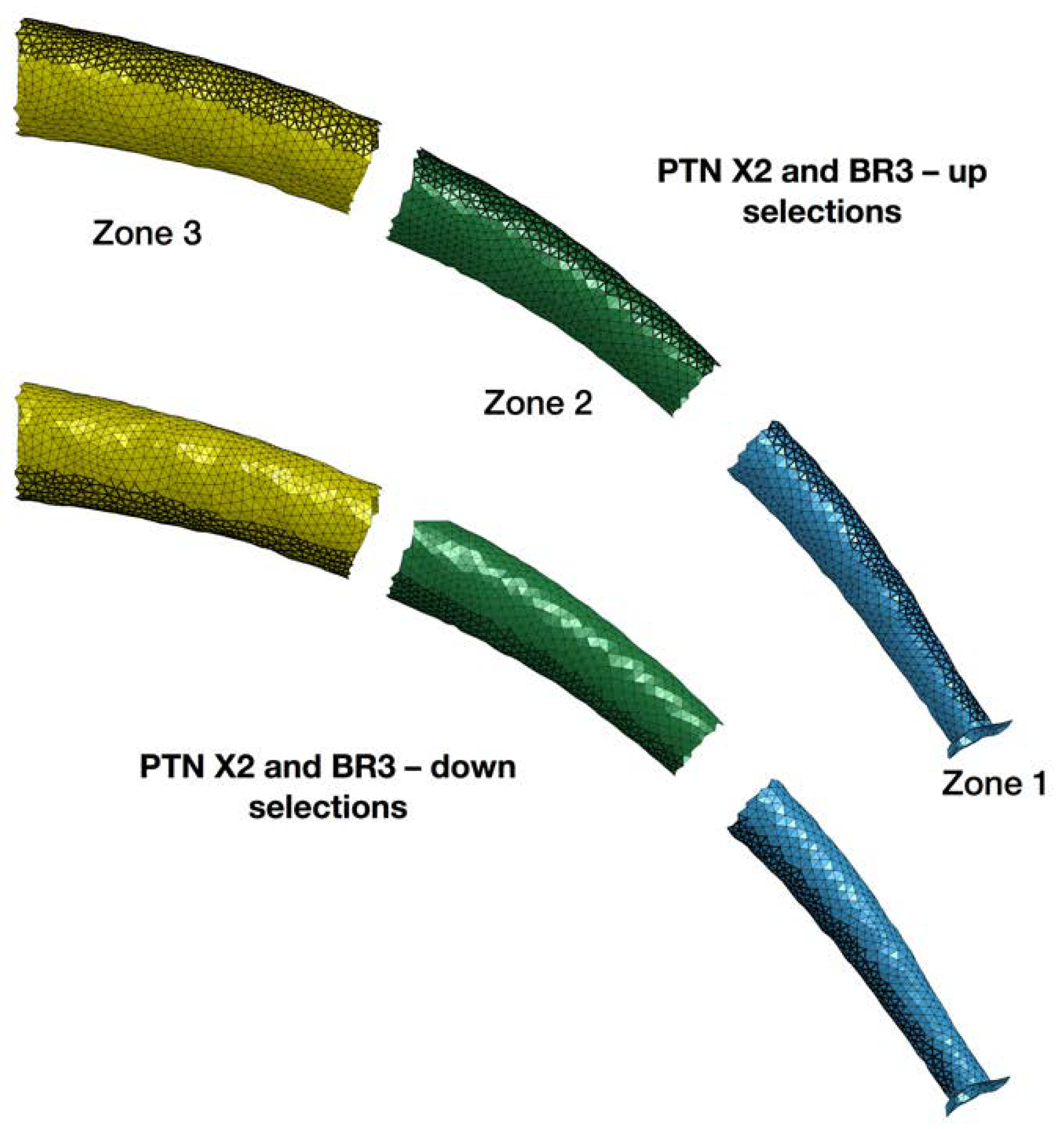
2.1. Geometrical Model

Both Training Blocks were CT scanned and computer replicated after shaping with Computer Aided Design (CAD) software (Altair Hypermesh 12.0, Troy, MI, USA). ProTaper Next (PTN) X2 and BioRace (BR) 3 shaping instruments were considered, being the last used in the shaping sequences. File geometries were computer-replicated with the same CAD software, starting from bidimensional industrial drawings.

2.2. Meshing Procedure
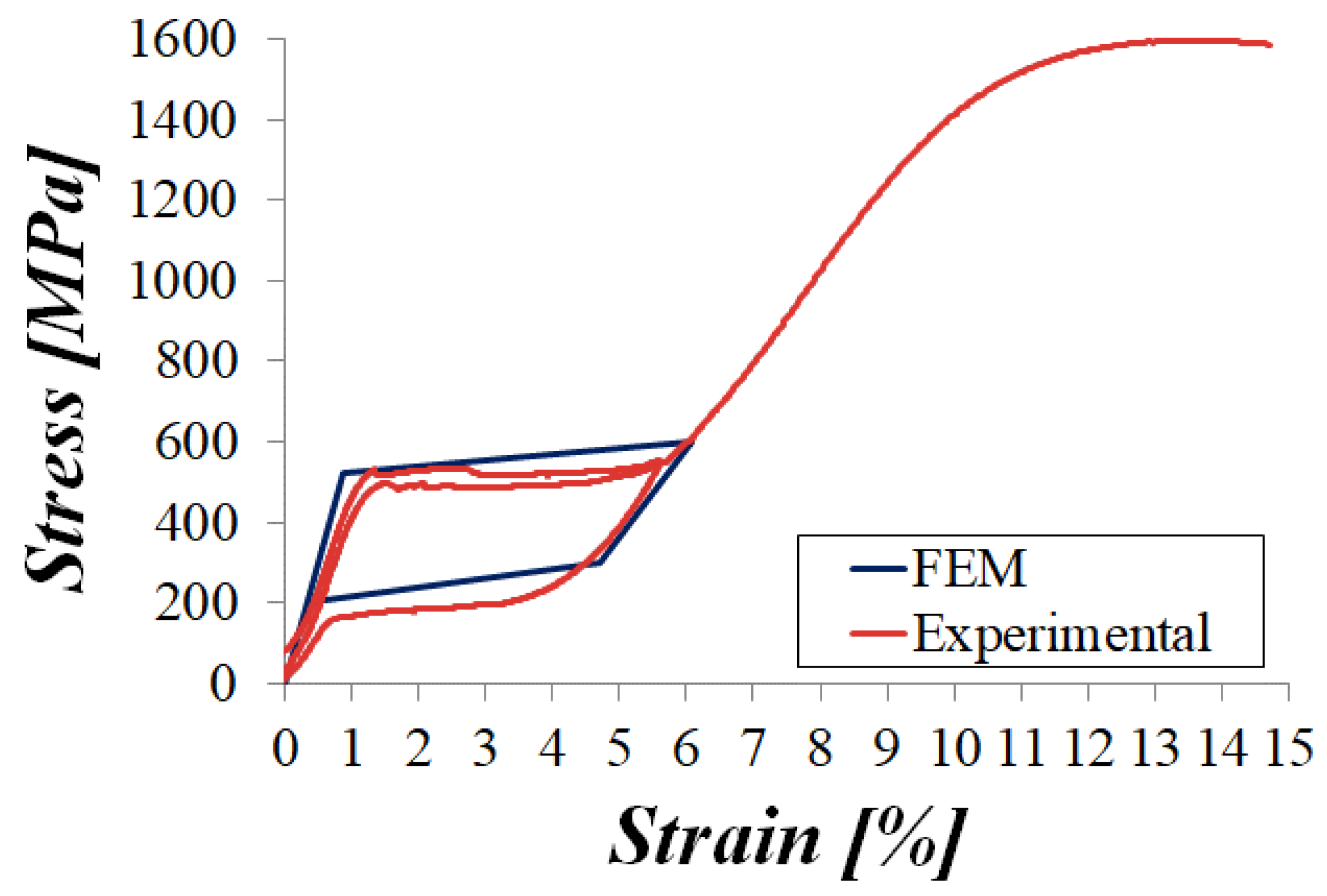
CAD geometries (geometrical models) of both shaped Training Blocks and of the two shaping instruments were discretized into finite element models (numerical models) by using dedicated software (Altair Hypermesh 12.0, Troy, MI, USA). For the resin blocks four layers of brick elements were used, extruding the interior surface of the canal. The main body of each NiTi instrument was modeled with brick elements, starting from the cross section of the instrument and with extrusion and revolution operations (LS-Dyna R7.1, Livermore, CA, USA). Up to 8500 and 4300 brick elements were used for PTN X2 and BR 3 files, respectively, with an average element size equal to 0.1 mm. The tip and the neck of the files were modeled with tetrahedral elements with the same average dimensions.

2.3. Material Model

An isotropic elastic linear model with the mechanical properties of the dentin [22] was adopted for the Training Blocks. The material model proposed by Auricchio et al. was adopted [23] (LS-Dyna R7.1, Livermore, USA) for the shape memory alloy behavior of both shaping instruments. The material parameters were set up in agreement with the results of the experimental tensile tests carried out on the file by the manufacturers. Table 1 reports the material parameters adopted for the model.
The comparison between the experimental and the numerical material behavior obtained with the finite element method (FEM) is shown in Figure 1.

2.4. Boundary Conditions
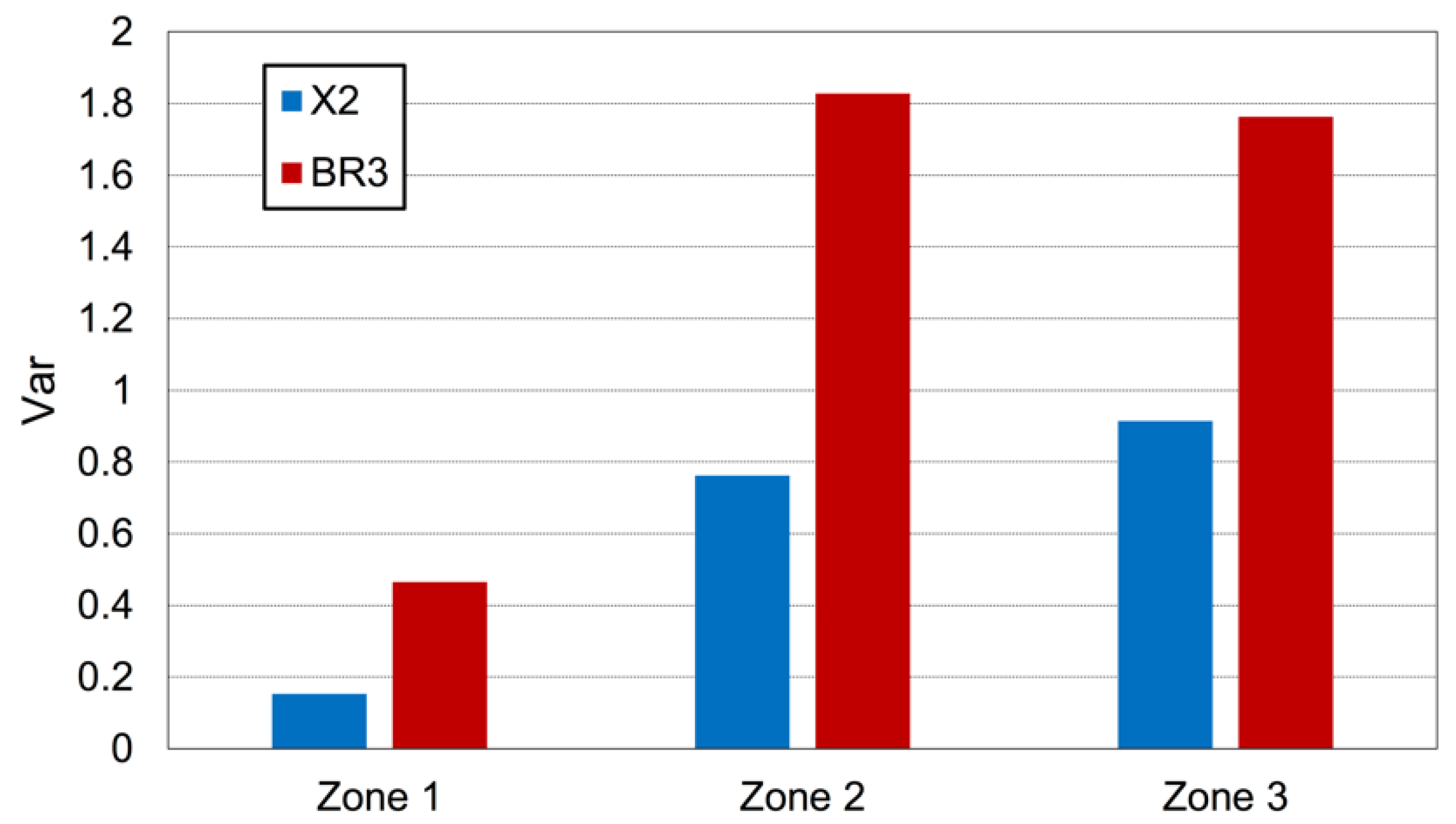
The contact between NiTi instruments and the virtual canal walls was taken into account through a penalty algorithm implemented in LS-Dyna. Finite element simulations were performed according to two different configurations, in order to mimic the push-pull actions of the operator during the canal instrumentation. In the first one, the instruments were inserted into the canal, applying a constant insertion force on the instrument neck equal to 2.5 N. The direction of the force (push force in the following) was the same as that of the rotational axis of the file in the neck section. A constant rotational speed equal to the one used in the experimental test, was also applied to the instruments. This type of simulation was replicated five times for each instrument, considering a slightly different starting position of the instrument neck. The starting position of the neck was defined with a random algorithm. Starting from the position reached by the instruments into the canal at the end of the simulation, the second configuration for the simulation was then defined. The tips of the instruments were constrained in the position reached. An extraction force of 2.5 N was then applied to the neck of the instruments. This force (pull force in the following) was applied as in the first configuration but with opposite direction. The constant rotational speed was also applied in this second configuration. The pressures applied by the files against the canal walls were recorded during the simulation time for both configurations. All simulations were carried out for 5 s. For the subsequent pressure analysis, the apical portion was considered. It was divided in three zones (namely Zone 1, Zone 2 and Zone 3) of about 2 mm in length each (Figure 2). Each zone was further subdivided in two parts: Top, for the root canal portion outside the curvature, and Down, for the root canal portion inside the curvature (Figure 2).

3. Results

Figure 3 shows a typical graph for the different pressure trends arising during the insertion phase on the top part of Zone 2. The five different random starting positions are considered.
As depicted in Figure 3, no significant differences between the pressure curves were present in the various insertion simulations. These results were confirmed for each instrument, each zone and both for Top and Down portions.

Evaluation of FEA Results

The integral of the pressure as a function of the time was evaluated for each simulation. The integrals were evaluated in the window of time 0.5–2.1 s because in this time interval, all the simulations showed a constant trend. The average value of the pressure integral between the push and pull configurations was calculated both for the Top and for the Down portion of the canal. These two values were used to evaluate the parameter Var, defined as follows:
V a r z o n e = | p ¯ z o n e , T o p p ¯ z o n e , D o w n | p ¯ z o n e , T o p + p ¯ z o n e , D o w n 2
where | x | denotes the absolute value of x and p ¯ z o n e , T o p and p ¯ z o n e , D o n w are the average values of the pressure integral for the Top and for the Down portion, respectively. The larger the Var variable, the larger the difference in the pressure values between the Top and the Down portions. Therefore, smaller Var values refer to a better canal centering ability during instrumentation.
Data resulting from mathematic analysis are shown in Figure 4. The Var variables for each zone and for both rotary instruments were evaluated. For each zone, the Var values reported for the BR instrument were systematically larger than those for the PTN instrument.

4. Discussion

It is well known that a correct shaping is fundamental for the endodontic success. Especially in case of complex anatomies, a less invasive approach leads to a better prognosis [24,25]. Instrument alloy and other geometrical variables influence the shaping behavior of the endodontic files [1,2,4,5,6,9,10,12]. The super-elasticity of modern NiTi instruments reduces the occurrence of canal aberrations and allows for a more centered root canal preparation [9,10,26]. Canal centering ability is essential to provide a less invasive shaping, without removing exceeding radicular structure [27,28]. The instrument pressure patterns against the canal walls is a predictive indicator of the centering ability during shaping [4]. The invention of new endodontic instruments mostly occurs by industrial drawings and derived prototypes, which must pass severe laboratory tests before commercialization: this is a time-consuming and expensive process. FEA was firstly introduced in endodontics for the static analysis of the forces applied to the NiTi files [15,16,17,18,21]. Afterwards, a dynamic FEA was proposed for the visualization of the instrument mechanical stresses during shaping [17,18,19,29,30,31,32]. In all these studies, the differences found between the instruments were due to the geometry of the instruments and to the alloy stiffness: especially, it was demonstrated how the most rigid instruments caused the highest stress on the apical portion of the canal, confirming that these two instrument characteristics influence their mechanical behavior [4,19,26,33,34].
Since instrument pressures and their cutting capability may determine canal aberration and it is of utmost relevance to analyze these factors during the project management of endodontic instruments.
The discretization of the instruments and the root canals in which instruments rotate allows for a proper dynamic structural analysis during canal instrumentation. Recently, FEA has been introduced as a reliable virtual testing approach to predict the mechanical behavior of NiTi files through a reverse engineering approach [20]. The reliability of FEA for failure prediction was demonstrated by a strict correlation between virtual simulation results and in vitro laboratory tests in terms of the number of cycles to failure and of the localization of breaking points of PTN instruments [20]. Therefore, FEA could be considered as an effective aid for the dynamic analysis and prediction of the mechanical properties of the endodontic instrument [20]. However, nowadays, the shaping ability of the newly developed mechanical NiTi instruments is evaluated only after commercialization by using micro-CT studies [35,36]. Therefore, the virtual prediction of the instrument shaping ability through a dynamic FEA could significantly ease the design of even more performing instruments [20]. The possibility of a virtual modification of the instrument parameters during an early design phase could optimize the instrument behavior, avoiding the creation of several instruments’ prototypes. In the present study, the instruments and the shaped endodontic resin blocks were virtually replicated to perform a dynamic finite element analysis for the evaluation of the pressures generated during the canal instrumentation. Two widely used NiTi endodontic instruments with equal size and taper (#25, 0.06) at tip level but different design, alloy and sections were tested in standardized simulated root canals. The resin blocks were virtually reproduced after their shaping with the two different instrumentation systems, in order to obtain a dedicated enlargement of the root canals for each tested shaping instrument before applying FEA [36,37,38]. The pressures variation (Var value) against the Top and Down canal surfaces was systematically lower for PTN X2 than for BR 3 for each different zone of the root canal. Consequently, PTN X2 instrument seemed to remain more centered in the root canal during shaping. PTN rotary system is characterized by an M-wire technology and an offset centered rectangular cross section, which provides the characteristic swaggering motion during rotation [37]. Probably, the lower Var values for the PTN group may depend on the ability of the off-centered section to shape a determined volume with a thinner and more flexible file [37]. A previous micro-CT study showed a better preservation of the original root canal anatomy for PTN X2 than for BR 3 [37]. These micro-CT considerations fully respect the shaping predictions virtually obtained with FEA.

5. Conclusions

In conclusion, FEA is proposed as a possible innovative tool for the virtual prediction of the instruments’ shaping ability during an early design phase without the need for prototypes. It is possible to vary any geometrical variable of the instruments or the alloy and to analyze the results of the simulation in a short time. This technology may be implemented for the evaluation of even better performing NiTi instruments during an early design phase, positively influencing development time and costs.

Author Contributions

Conceptualization: G.C. (Giorgia Carpegna), M.A., D.P. and E.B.; methodology, A.S. and E.B.; formal analysis, D.S.P., G.C. (Giorgio Chiandussi), A.S.; investigation, D.S.P., A.S., G.C. (Giorgio Chiandussi), U.G. and A.M.; data curation, U.G., M.A., G.C. (Giorgia Carpegna) and N.S.; writing—original draft preparation, G.C. (Giorgia Carpegna) and M.A.; writing—review and editing, E.B. and D.S.P.; supervision, E.B. and D.P. All authors have read and agreed to the published version of the manuscript.

Funding

This research received no external funding.

Conflicts of Interest

The authors deny any conflicts of interest. The authors affirm that they have no financial affiliation (e.g., employment, direct payment, stock holdings, retainers, consultantships, patent licensing arrangements or honoraria) or involvement with any commercial organization with direct financial interest in the subject or materials discussed in this manuscript, nor have any such arrangements existed in the past years.

References

  1. Metzger, Z.; Solomonov, M.; Kfir, A. The role of mechanical instrumentation in the cleaning of root canals. Endod. Top. 2013, 29, 87–109. [Google Scholar] [CrossRef]
  2. Peters, O.A. Current challenges and concepts in the preparation of root canal systems: A review. J. Endod. 2004, 30, 559–567. [Google Scholar] [CrossRef] [PubMed] [Green Version]
  3. Schilder, H. Cleaning and shaping the root canal. Dent. Clin. North Am. Apr. 1974, 18, 269–296. [Google Scholar]
  4. Burklein, S.; Schafer, E. Critical evaluation of root canal transportation by instrumentation. Endod. Top. 2013, 29, 110–124. [Google Scholar] [CrossRef]
  5. Bergmans, L.; Van Cleynenbreugel, J.; Wevers, M.; Lambrechts, P. Mechanical root canal preparation with NiTi rotary instruments: Rationale, performance and safety: Status report for the American Journal of Dentistry. Am. J. Dent. 2001, 14, 324–333. [Google Scholar]
  6. Jafarzadeh, H.; Abbott, P.V. Ledge formation: Review of a great challenge in endodontics. J. Endod. 2007, 33, 1155–1162. [Google Scholar] [CrossRef]
  7. Bier, C.A.; Shemesh, H.; Tanomaru-Filho, M.; Wesselink, P.R.; Wu, M.K. The ability of different nickel-titanium rotary instruments to induce dentinal damage during canal preparation. J. Endod. 2009, 35, 236–238. [Google Scholar] [CrossRef]
  8. Tamse, A.; Fuss, Z.; Lustig, J.; Kaplavi, J. An evaluation of endodontically treated vertically fractured teeth. J. Endod. 1999, 25, 506–508. [Google Scholar] [CrossRef]
  9. Gambill, J.M.; Alder, M.; del Rio, C.E. Comparison of nickel-titanium and stainless steel hand-file instrumentation using computed tomography. J. Endod. 1996, 22, 369–375. [Google Scholar] [CrossRef]
  10. Gergi, R.; Rjeily, J.A.; Sader, J.; Naaman, A. Comparison of canal transportation and centering ability of twisted files, Pathfile-ProTaper system, and stainless steel hand K-files by using computed tomography. J. Endod. 2010, 36, 904–907. [Google Scholar] [CrossRef]
  11. Çapar, I.D.; Arslan, H. A review of instrumentation kinematics of engine-driven nickel-titanium instruments. Int. Endod. J. 2016, 49, 119–135. [Google Scholar] [CrossRef] [PubMed]
  12. Haapasalo, M.; Shen, Y. Evolution of nickel-titanium instruments: From past to future. Endod. Top. 2013, 29, 3–17. [Google Scholar] [CrossRef]
  13. Al-Sudani, D.; Al-Shahrani, S. A comparison of the canal centering ability of ProFile, K3, and RaCe Nickel Titanium rotary systems. J. Endod. 2006, 32, 1198–1201. [Google Scholar] [CrossRef]
  14. Zanesco, C.; Só, M.V.; Schmidt, S.; Fontanella, V.R.; Grazziotin-Soares, R.; Barletta, F.B. Apical transportation, centering ratio, and volume increase after manual, rotary, and reciprocating instrumentation in curved root canals: Analysis by micro-computed tomographic and digital subtraction radiography. J. Endod. 2017, 43, 486–490. [Google Scholar] [CrossRef]
  15. Berutti, E.; Chiandussi, G.; Gaviglio, I.; Ibba, A. Comparative analysis of torsional and bending stresses in two mathematical models of nickel-titanium rotary instruments: ProTaper versus ProFile. J. Endod. 2003, 29, 15–19. [Google Scholar] [CrossRef] [PubMed]
  16. Bonessio, N.; Pereira, E.S.; Lomiento, G.; Arias, A.; Bahia, M.G.; Buono, V.T.; Peters, O.A. Validated finite element analyses of WaveOne Endodontic Instruments: A comparison between M-Wire and NiTi alloys. Int. Endod. J. 2015, 48, 441–450. [Google Scholar] [CrossRef]
  17. Kim, H.C.; Kim, H.J.; Lee, C.J.; Kim, B.M.; Park, J.K.; Versluis, A. Mechanical response of nickel-titanium instruments with different cross-sectional designs during shaping of simulated curved canals. Int. Endod. J. 2009, 42, 593–602. [Google Scholar] [CrossRef]
  18. Kim, T.O.; Cheung, G.S.; Lee, J.M.; Kim, B.M.; Hur, B.; Kim, H.C. Stress distribution of three NiTi rotary files under bending and torsional conditions using a mathematic analysis. Int. Endod. J. 2009, 42, 14–21. [Google Scholar] [CrossRef]
  19. Lee, M.H.; Versluis, A.; Kim, B.M.; Lee, C.J.; Hur, B.; Kim, H.C. Correlation between experimental cyclic fatigue resistance and numerical stress analysis for nickel-titanium rotary files. J. Endod. 2011, 37, 1152–1157. [Google Scholar] [CrossRef]
  20. Scattina, A.; Alovisi, M.; Paolino, D.S.; Pasqualini, D.; Scotti, N.; Chiandussi, G.; Berutti, E. Prediction of Cyclic Fatigue Life of Nickel-Titanium Rotary Files by Virtual Modeling and Finite Elements Analysis. J. Endod. 2015, 41, 1867–1870. [Google Scholar] [CrossRef] [Green Version]
  21. Xu, X.; Eng, M.; Zheng, Y.; Eng, D. Comparative study of torsional and bending properties for six models of nickel-titanium root canal instruments with different cross-sections. J. Endod. 2006, 32, 372–375. [Google Scholar] [CrossRef]
  22. Lazari, P.C.; Oliveira, R.C.; Anchieta, R.B.; Almeida, E.O.; Freitas Junior, A.C.; Kina, S.; Rocha, E.P. Stress distribution on dentin-cement-post interface varying root canal and glass fiber post diameters. A three- dimensional finite element analysis based on micro-CT data. J. Appl. Oral Sci. 2013, 21, 511–517. [Google Scholar] [CrossRef] [PubMed] [Green Version]
  23. Auricchio, F.; Taylor, R.L.; Lubliner, J. Shape-memory alloys: Macromodelling and numerical simulations of the superelastic behavior. Comput. Methods Appl. Mech. Engrg. 1997, 146, 281–312. [Google Scholar] [CrossRef]
  24. Hartmann, M.S.; Barletta, F.B.; Camargo Fontanella, V.R.; Vanni, J.R. Canal transportation after root canal instrumentation: A comparative study with computed tomography. J. Endod. 2007, 33, 962–965. [Google Scholar] [CrossRef] [PubMed]
  25. Capar, I.D.; Ertas, H.; Ok, E.; Arslan, H.; Ertas, E.T. Comparative study of different novel nickel-titanium rotary systems for root canal preparation in severely curved root canals. J. Endod. 2014, 40, 852–856. [Google Scholar] [CrossRef] [PubMed]
  26. Gundappa, M.; Bansal, R.; Khoriya, S.; Mohan, R. Root canal centering ability of rotary cutting nickel titanium instruments: A meta-analysis. J. Conserv. Dent. 2014, 17, 504–509. [Google Scholar] [CrossRef]
  27. Elnaghy, A.M.; Elsaka, S.E. Evaluation of root canal transportation, centering ratio, and remaining dentin thickness associated with ProTaper Next instruments with and without glide path. J. Endod. 2014, 40, 2053–2056. [Google Scholar] [CrossRef]
  28. Stern, S.; Patel, S.; Foschi, F.; Sherriff, M.; Mannocci, F. Changes in centering and shaping ability using three nickel–titanium instrumentation techniques analyzed by micro-computed tomography (μCT). Int. Endod. J. 2012, 45, 514–523. [Google Scholar] [CrossRef]
  29. Ha, J.H.; Cheung, G.S.; Versluis, A.; Lee, C.J.; Kwak, S.W.; Kim, H.C. ‘Screw-in’ tendency of rotary nickel- titanium files due to design geometry. Int. Endod. J. 2015, 48, 666–672. [Google Scholar] [CrossRef]
  30. Kim, H.C.; Cheung, G.S.; Lee, C.J.; Kim, B.M.; Park, J.K.; Kang, S.I. Comparison of forces generated during root canal shaping and residual stresses of three nickel-titanium rotary files by using a three-dimensional finite-element analysis. J. Endod. 2008, 34, 743–747. [Google Scholar] [CrossRef]
  31. Arbab-Chirani, R.; Chevalier, V.; Arbab-Chirani, S.; Calloch, S. Comparative analysis of torsional and bending behavior through finite-element models of 5 Ni-Ti endodontic instruments. Oral Surg. Oral Med. Oral Pathol. Oral Radiol. Endod. 2011, 111, 115–121. [Google Scholar] [CrossRef] [PubMed]
  32. Tsao, C.C.; Liou, J.U.; Wen, P.H.; Peng, C.C.; Liu, T.S. Study on bending behavior of nickel-titanium rotary endodontic instruments by analytical and numerical analyses. Int. Endod. J. 2013, 46, 379–388. [Google Scholar] [CrossRef] [PubMed] [Green Version]
  33. Adorno, C.G.; Yoshioka, T.; Suda, H. Crack initiation on the apical root surface caused by three different nickel-titanium rotary files at different working lengths. J. Endod. 2011, 37, 522–525. [Google Scholar] [CrossRef]
  34. Liu, R.; Kaiwar, A.; Shemesh, H.; Wesselink, P.R.; Hou, B.; Wu, M.K. Incidence of apical root cracks and apical dentinal detachments after canal preparation with hand and rotary files at different instrumentation lengths. J. Endod. 2013, 39, 129–132. [Google Scholar] [CrossRef] [PubMed]
  35. Peters, O.A.; Schönenberger, K.; Laib, A. Effects of four Ni-Ti preparation techniques on root canal geometry assessed by micro computed tomography. Int. Endod. J. 2001, 34, 221–230. [Google Scholar] [CrossRef]
  36. Berutti, E.; Cantatore, G.; Castellucci, A.; Chiandussi, G.; Pera, F.; Migliaretti, G.; Pasqualini, D. Use of nick- el-titanium rotary PathFile to create the glide path: Comparison with manual preflaring in simulated root canals. J. Endod. 2009, 35, 408–412. [Google Scholar] [CrossRef]
  37. Pasqualini, D.; Alovisi, M.; Cemenasco, A.; Mancini, L.; Paolino, D.S.; Bianchi, C.C.; Roggia, A.; Scotti, N.; Berutti, E. Micro-Computed Tomography Evaluation of ProTaper Next and BioRace Shaping Outcomes in Maxillary First Molar Curved Canals. J. Endod. 2015, 41, 1706–1710. [Google Scholar] [CrossRef]
  38. Yoshimine, Y.; Ono, M.; Akamine, A. The shaping effects of three nickel-titanium rotary instruments in simulated S-shaped canals. J. Endod. 2005, 31, 373–375. [Google Scholar] [CrossRef]
Figure 1. Experimental tests on the nickel-titanium (NiTi) alloy mechanical behavior (in red) compared to the obtained finite element (FE) behavior (in blue). The stress-strain diagram was obtained by gradually applying a load to the sample and measuring the deformation, FEM = finite element method.
Applsci 10 02981 g001
Figure 2. The division in different zones of the virtually replicated canals (Zone 1, Zone 2 and Zone 3). The three zones of 2 mm length are equally distributed from the apical third of the root canal. Top (root canal portion outside the curvature) and Down (root canal portion inside the curvature) areas of the simulated root canals are shown in black.
Applsci 10 02981 g002
Figure 3. The pressures entity during the different random insertions of the PTN X2 in the simulated canal (specifically Zone 2, Top). The pressures during all the insertions are comparable.
Applsci 10 02981 g003
Figure 4. The difference between the Top/Down pressures (Var) is significantly less for PTN X2 compared to BR 3 instrument for each zone.
Applsci 10 02981 g004
Table 1. Material parameters adopted in the finite element model.
Material ParameterValues [ M P a ]
E (Young’s modulus)60,000
σASS (austenite-martensite, starting stress)520
σASF (austenite-martensite, final stress)600
σSAS (martensite-austenite, starting stress)300
σSAF (martensite-austenite, final stress)200

