Article

Investigation of Structural Stability for Monolithic Nano Bridges on Micro Apertures

1
Department of Mechanical Engineering, Incheon National University, Incheon 22012, Korea
2
Department of Mechanical Engineering, Hanbat National University, Daejeon 34158, Korea
3
John A. Paulson School of Engineering and Applied Science, Kavli Institute for Bionano Science and Technology, Harvard University, Cambridge, MA 02138, USA
4
Science and Technology Studies, Program in History and Philosophy of Science, College of Natural Sciences, Seoul National University, Seoul 08826, Korea
5
Sensor System Research Center, Korea Institute of Science and Technology, Seongbuk-gu, Seoul 02792, Korea
6
Division of Thermal and Fluids Science, Institute for Computational Science, Faculty of Electrical and Electronics Engineering, Ton Duc Thang University, Ho Chi Minh City 700000, Vietnam
*
Authors to whom correspondence should be addressed.
These authors contributed equally to this work.
Appl. Sci. 2020, 10(8), 2922; https://doi.org/10.3390/app10082922
Submission received: 4 April 2020 / Revised: 19 April 2020 / Accepted: 20 April 2020 / Published: 23 April 2020
(This article belongs to the Special Issue 3D Nanostructured Materials and Devices)

Abstract

:
The instability of polymeric membranes with nano- and micro-sized apertures has been regarded as one of the main reasons behind realizing ultra-thin membranes with apertures. As is well known, when the thickness of the membrane gets thinner or the aperture size gets smaller, the possibility of geometrical deformation or structural damage by collapse or fracture increases. Herein, we suggest the design rules for the stability of polymeric membranes possessing 1D nano-line patterns monolithically constructed on micro-aperture supporting layers. The proposed theoretical model, which has been thoroughly demonstrated and analyzed based on both theoretical and experimental approaches, provides stability criteria for lateral collapse and vertical fracture of ultra-thin membranes with apertures.

1. Introduction

Thin membranes possessing micro-/nano-scaled apertures have been extensively developed for a wide range of applications, including deposition masks, lithography masks, etching masks, microfluidic devices and filters [1,2,3,4,5,6,7]. A variety of techniques to improve the stability of the nanostructured membrane have been explored using diverse materials, factoring in corresponding surface energy, elasticity, transparency and surface hydrophilicity, depending on its purpose. When it comes to the thin membrane with a precisely controlled aperture size and arrangement, nanostructured silicon nitride (SiNx) membranes supported on rigid Si membranes have been used due to its superiority in mechanical rigidity as well as structural controllability [4]. Due to its rigidity, the ultra-thin layer of the SiNx membrane is likely to suffer from mechanical damage (cracks, breakdown, fractures, etc.) during handling for fabrication processes. It also requires complicated processes with high fabrication costs. As one of the contenders, free-standing stencils with polydimethylsiloxane (PDMS) has been fabricated through a soft lithography process thanks to several advantages, such as a low cost, conformal contact, flexibility, ease of process, the low mechanical strength and low elastic modulus, which rules out possible physical damages [8]. However, an implementation of polymeric flexible materials has its benefits, such as inducing folding/crumpling phenomena during the fabrication process, which leads to a limit in the aperture size and thickness [9,10]. To address these issues, a polymeric nano-aperture membrane monolithically constructed on a supporting layer with micro-apertures was reported previously [11,12]. The one-step process based on the scavenging effect of the infiltrated oxygen gas is highly advantageous in the facile fabrication of free-standing membranes with nano/micro two-level apertures. Furthermore, the stability of the periodically arranged nano-holes supported on microscale circular apertures, considering the adhesion forces in the demolding process, has been investigated to realize the stable fabrication of ultrathin membranes with nano-scale apertures [13]. Unlike 2-dimensionally (2D) closed-hole patterns on the polymeric membrane, the construction of a 1D line-patterned membrane causes directionally sensitive structural instability during the demolding or handling process in two aspects: The one is the lateral-direction collapse of the neighboring nano bridges, and the other is the vertical-direction fracture of the nano bridges. To overcome these issues in reliable reproduction, a 3D approach should be considered for improved mechanical stability.
Herein, we report the design rule in the formation of the 1D nano-line membrane over the micro-hole supports, which provides the geometrical restriction for the design of polymeric membranes with two-level apertures. To investigate the overall 3D mechanical stability, we conducted six sets of 1D line-shaped polymeric membranes with varying micro-pillar diameters (5 μm, 10 μm, 50 μm, 100 μm, 300 μm and 500 μm) in fixed conditions with a nano-line width (w) of 800 nm. From the results, we categorized the structures in three cases: (1) stable, (2) collapse and (3) fracture, and suggest a model that explains the physical mechanism of the lateral collapse with the vertical fracture during the demolding process when peeled-off from the micro molds.

2. Materials and Methods

2.1. Materials

Commercially available UV-curable resin purchased from Changsung sheet (Korea, MINS-311RM, PUA 311) was used in the experiments. The PUA resin was made up of a UV-curable releasing agent, photo-initiator and pre-polymer, with acrylate functional groups for the crosslinks.

2.2. Preparation of the PDMS Micro- and Nano-Patterned Array Mold

The micro-pillar- and nano-line-patterned PDMS molds were prepared by pouring the PDMS on hole- and line-patterned silicon masters. Patterned silicon masters were fabricated by photolithography and deep reactive ion etching. The surface of the silicon masters was coated with C4F8 gas for easier detachment of the PDMS polymer. After mixing the base resin and curing agent of the Sylgard 184 PDMS elastomer (Dupont, Wilmington, Delaware, United States) with a weight ratio of 10:1, the mixed PDMS resin was poured onto the patterned silicon master molds and cured over 2 h at 70 ℃. The completely cured PDMS molds were detached from the masters and cut for proper size.

2.3. Fabrication of the Monolithic Nano Bridges on Micro Apertures

The micro-pillar-patterned PDMS molds (5 μm, 10 μm, 50 μm, 100 μm, 300 μm and 500 μm in diameter) and nano-line-patterned PDMS molds (800 nm in width) were prepared. After dispensing PUA 311 resin on the micro-pillar-patterned PDMS mold, we covered the nano-line-patterned PDMS mold on it. The prepared assembly was exposed to UV light (SANKYO DENKI, F8T5BL, λ ~ 352 nm) with an intensity of 20 W/cm2 for 2 min in a custom-built UV exposure equipment. The UV curing process was carried out under conditions of ambient temperature and pressure (25 °C, 1 bar) with the distance between the assembly and the UV lamp being 8.5 cm. The nano-line-patterned PDMS mold was detached from the polymeric assembly first and the cured polymeric membrane was detached from the micro-pillar-patterned PDMS mold. Through the process, a free-standing and flexible multi-level polymeric membrane with a large area (3 cm × 3 cm) was obtained in a reproducible way. To get the completely cured multi-level membrane, the membrane was exposed to UV light for more than 4 h.

2.4. Physical Analysis

The scanning electron microscopy images were obtained using field-emission scanning electron microscopy FE-SEM (JEOL, JSM-7800F) with an acceleration voltage of 10.0 kV.

3. Results and Discussion

In order to handle and use the nano bridges as a mask or filters, supporting layers with micro-sized apertures for free-standing nano bridges are required. It is generally known that as the size of the apertures of the supporting layer gets wider or bigger, the extremely thin bridges get unstable, inducing collapse or fracturing of the bridges. Hence, a proper geometrical design for the fabrication of two-level multiscale polymeric membranes is needed. To investigate the mechanical stability of the monolithic nano bridges on the micro apertures, the diameter of the micro-pillars PDMS molds were varied, while the geometry of the nano-line was fixed. In this study, the micro-pillar PDMS molds with a diameter of 5 μm, 10 μm, 50 μm, 100 μm, 300 μm and 500 μm, and the nano-lines mold with a line width of 800 nm, were used to construct the two-level multiscale polymeric membrane. The spacing ratio (SR: spacing between pillars (or lines) divided by diameter (or line width)) of all the PDMS molds was the same. The scanning electron microscopy (SEM) images of six types of micro-pillars and one type of nano-lines PDMS mold are shown in Figure 1; the detailed information about the fabrication process of the patterned silicon master and PDMS molds is provided in the Materials and Methods section.
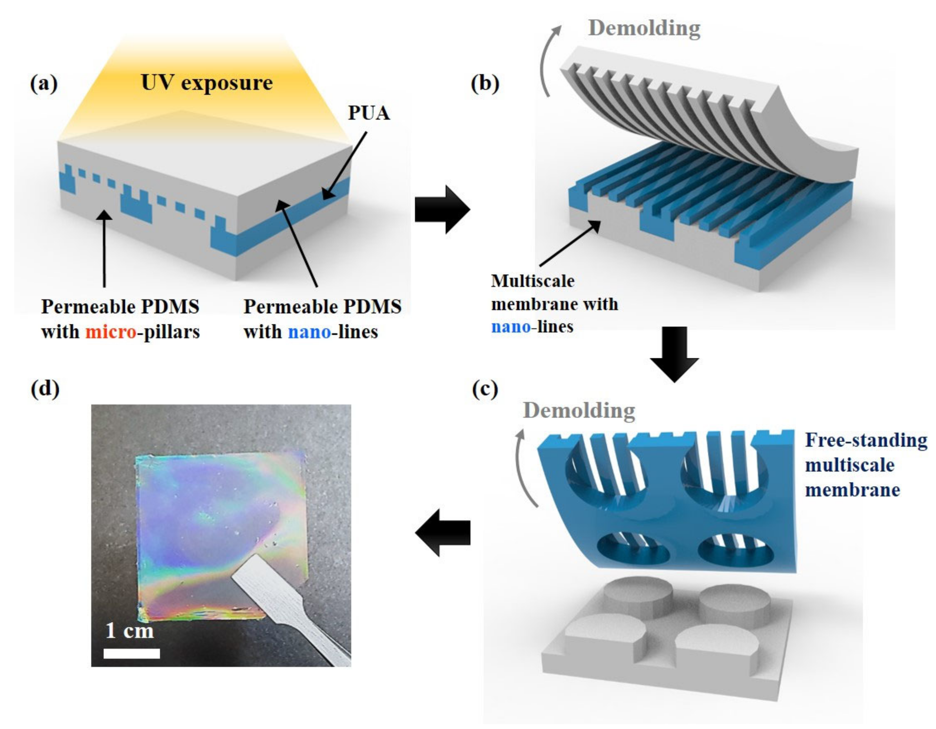
The fabrication process of the two-level multiscale polymeric membrane is illustrated in Figure 2. The multiscale polymeric membranes were fabricated by using the UV-curable polyurethane acrylate (PUA) resin, micro-pillars PDMS mold and nano-lines PDMS mold. First, the PDMS resin was poured onto the Si master molds of the nano-lines and micro-pillars and cured at 70 ℃ for 2 h to obtain the PDMS patterned molds [13]. Then, PUA pre-polymer was dispensed onto the micro-pillar PDMS mold and the nano-line PDMS mold was placed on it. The contact surface area between the nano-lines and micro-pillars formed overlapped oxygen-infiltrated layers (OILs) due to the gas permeable property of the PDMS, which resulted in delayed UV curing under the ultraviolet irradiation at the contact area [7,14,15,16]. The sandwiched layers (nano-lines PDMS mold–PUA resin–micro-pillars PDMS mold) were properly irradiated with UV light with an intensity of 20 W cm−2 for 2 min. After the cured PUA membrane was detached from the PDMS mold, the membrane was treated with UV curing for 4 h to fully treat the partially cured resin on the surface. After the fabrication process, the free-standing two-level multiscale polymeric membrane, which includes the monolithic nano bridges over the micro apertures, was obtained, as shown in Figure 1d. The uniform iridescent color of the membrane indicates that the nano-lines were successfully constructed over the large area (~3 cm × 3 cm).
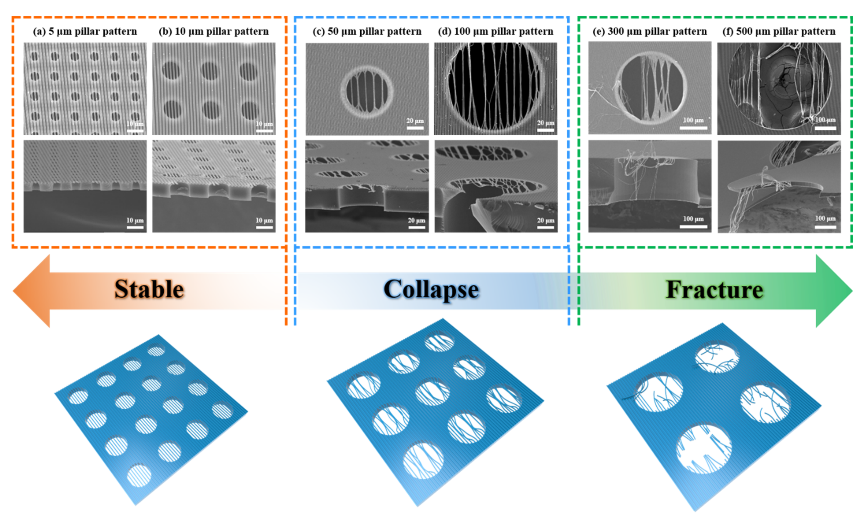
With the prepared PDMS molds and PUA pre-polymer resin, the two-level multiscale polymeric membranes have been successfully constructed through the fabrication process, and the six types of nano bridges monolithically constructed on the micro-aperture membrane were observed through SEM, as shown in Figure 3. The results show that the nano bridges are stably sustained on the supporting layer of the micro-aperture structures with a diameter of 5 μm and 10 μm. In other cases, structural failures of nano bridges occurred, meaning that the nano bridges were deformed, fractured or unsupported by the layer. The failures are classified by two cases, which are the collapse of thin nano bridges in the lateral direction and fracture of the bridges in the direction perpendicular to the line direction. In the cases of the 50 μm and 100 μm sizes of the supporting layer, which are relatively smaller than that of the 300 μm and 500 μm sizes, the centers of the nano bridges were collapsed or clustered together. In turn, in the case of the 300 μm and 500 μm micro aperture sizes of the supporting layer, fracture and collapse of the nano bridges occurred simultaneously during the detaching process. As the micro aperture size of the supporting layers increases, the thin nano bridge structures get unstable, as expected. From the observation, the finally constructed two-level multiscale polymeric membrane can be categorized in mainly three cases: (1) stable, (2) collapse and (3) fracture and collapse. To analyze these phenomena and set the criteria for each stability, it is necessary to separate the observational view of the structures. Since the collapse, which is determined by the geometrical features of line width, the gap width of the lines and the micro aperture size should be considered in the top view of the structure. In turn, the fracture, which is determined by the geometrical features of line thickness, and the micro aperture size should be considered in the side view of the structures.
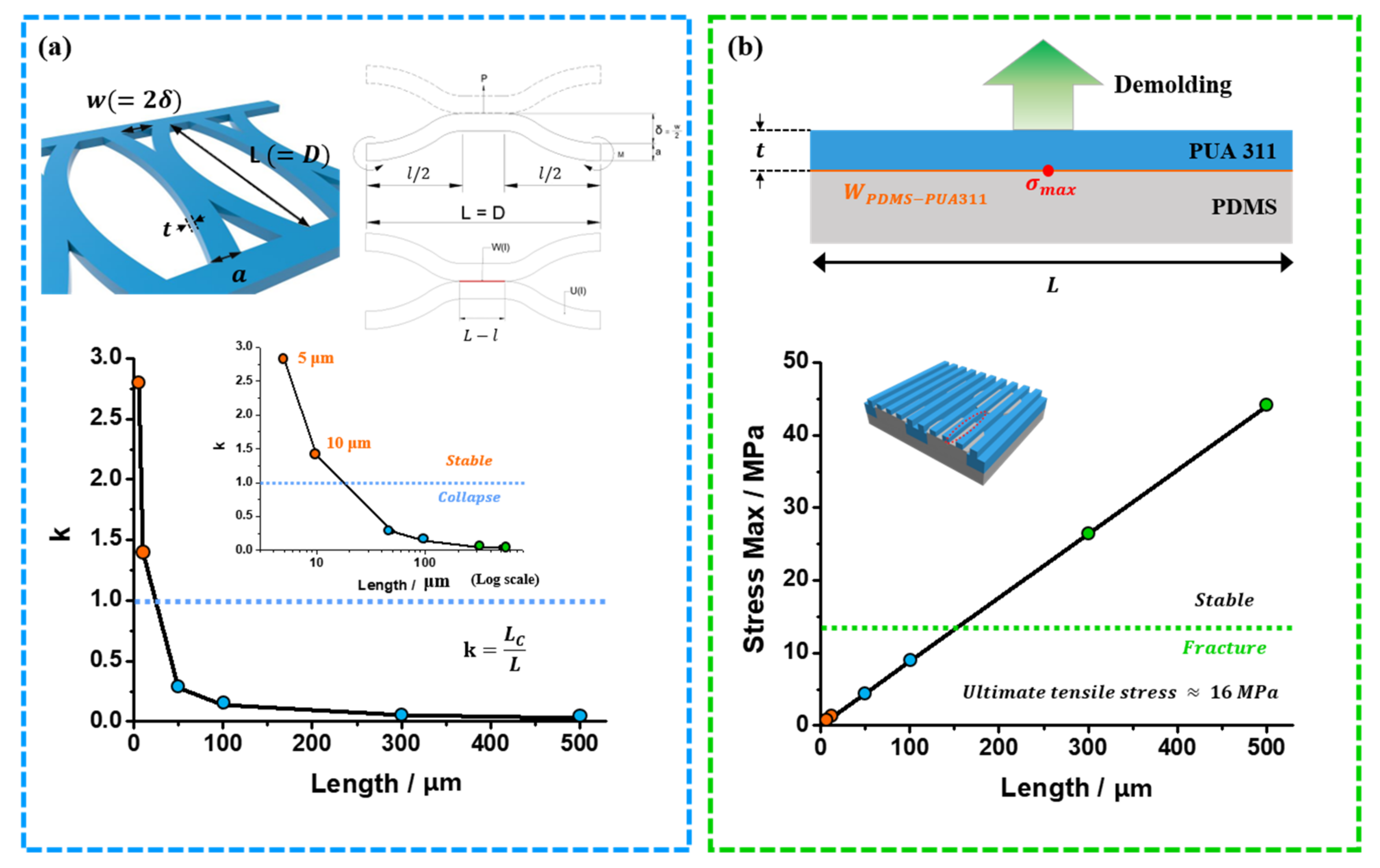
In order to propose simple theoretical models to set the stability criteria for the collapse phenomenon in the lateral direction and fracture phenomenon in the vertical direction, a model where the beam structure and nano bridge are fixed at both ends is assumed. First, to establish a criterion for lateral stability of the nano bridges, we model the collapsing of the bridges as depicted in the inset of Figure 4a, in which two neighboring line bridges adhere to each other. The adhesion between the bridges induces a distributed bending moment M(x) with an adhesion force, P.
M x = P 2 x P L 8 ,     x = 0 ,   L 2 P 2 x + 3 P L 8 ,     x = L 2 ,   L    
where L is length of the bridge, which is same with the diameter of the micro aperture.
Then, the strain energy (U) of the deformed structure can be given as follows:
U = 0 L M x 2 2 E I d x = P 2 L 3 384 E I
The contact region is set to be located at the center of the bridge because it gives the minimum strain energy at a given geometry. Let l be the length of the non-contact region where the elastic strain energy is stored. The bridges will not collapse when L− l < 0. Thus, l is the minimum length of the bridge to be stable. We denote Lc as a critical length of l. The strain energy of the non-contact area of the bridges, where bending deformation is dominant, is stored, while that of the contact area is not stored [17,18]. Based on the assumption, the total strain energy of the system is expressed as follows:
U = P 2 l 3 384 E I = P δ 2
where E is elastic modulus, δ is deflection length of the bridge and I is second moment of inertia of the deflected bridge, I = ta3/12 (a: width of bridge; t: thickness of bridge). From the relation, U is defined as a function of the geometrical features.
U l = 8 E δ 2 t a 3 l 3
Regarding energy conservation, the energy balance between the adhesion energy and strain energy is expressed as follows:
d U d l + d E a d d l = 0
E a d l = 2 γ s t L l
where γ s ( or   γ s v ) is the surface energy of the bridges, which is calculated based on the geometric mean method.
γ l v   1 + c o s θ = 2 γ s v d γ l v d 1 / 2 + 2 γ s v p γ l v p 1 / 2
where γ l v is the surface tension of liquid, θ is the contact angle of the liquid on the solid surface, superscript d refers to disperse and superscript p refers to polar. By measuring the contact angle of two liquid materials, which are DI water and ethylene glycol on the surface, the surface energies in the polar term and in the disperse term are calculated, respectively (Figure 5). The total surface energy (γ) of solid material is obtained by adding up the two terms of surface energy (Table 1).
Then, the critical length is determined as follows:
l = L C = 12 E δ 2 a 3 γ s 1 / 4
If we denote k as a stability indicator, then
k = L C L = l L = 1 L 12 E δ 2 a 3 γ s 1 / 4
Then, the condition for lateral stability is k > 1 . In this case, the structure would be stable. If k ≤ 1, the structures would be laterally collapsed. As shown in graph in Figure 4a, in our experimental set, the lateral collapse would occur except for the case of 5 μm and 10 μm, in which the k value is over 1. The anticipated results based on the criteria are in good agreement with the experimental results. It can be used toward the design rule for the lateral collapse of nano-layers constructed on the micro-aperture structures.
When the nano-line length was 300 and 500 μm, not only the collapse phenomenon of the nano bridges but also the fracture phenomenon at the center of the nano bridges was observed. To elucidate this phenomenon, we proposed a model of mechanical stability of the beams fixed at both ends under constant distributed loads [13]. When the beam fixed at both ends was under the uniformly distributed load, the maximum allowable stress can be derived as follows [19]:
σ m a x = M c e n t e r y m a x I = q L 2 t 2   ,     I = L t 3 12
where Mcenter is the moment at the center of the beam, ymax is the maximum distance across the beam from the center of the beam, I is the area moment of inertia of the beam, q is the stress applied to the beam and h is the length of the beam. The allowable beam deflection at the center of the beam is assumed to not exceed the thickness of the nano bridge (~ 400 nm), and the applied stress q is the work of adhesion required to detach the PUA 311 membrane from the PDMS mold. At the center of the nano-bridges is applied the maximum stress. It is generally known that the fracture of the structure occurs when the applied stress exceeds the ultimate tensile stress (~16 MPa) [20,21]. To calculate the work of adhesion, we used following harmonic mean method equations:
W 12 = 4   γ 1 p γ 2 p γ 1 p + γ 2 p + γ 1 d γ 2 d γ 1 d + γ 2 d  
where the superscripts p and d are for the polar and dispersed components of the surface tension γ, respectively; these values are summarized in Table 1. The calculated work of adhesion is about 28.14 mJ/m2, which is a uniformly distributed load on the nano bridges when the PUA membrane was detached from the PDMS mold. Therefore, Equation (10) can be substituted with the following equation:
σ m a x = W L 2 t 2
From Equation (12), we can calculate the maximum applied stress depending on the length of nano bridge structures. Figure 4b shows the illustration of the work of adhesion at the interface between the PDMS mold and PUA 311 nano-layers, as well as the plotted maximum tensile stress for the cases 5 μm, 10 μm, 50 μm, 100 μm, 300 μm and 500 μm. As shown in the graph, the maximum applied stress of the 100 μm and lower pore diameter is lower than ultimate tensile stress of PUA 311. As a result, the fracture phenomenon is not observed for nano bridges supported on micro-aperture diameters of 5 μm, 10 μm, 50 μm and 100 μm. Contrariwise, the maximum applied stress of the 300 μm and 500 μm pore diameters is higher than the ultimate tensile stress of PUA 311, and some fractures are observed as unstably supported on the micro-aperture. These design rules can be used as a guideline for the fabrication of flexible and free-standing membranes with nano-line structures monolithically constructed on the micro-aperture membrane.

4. Conclusions

In this paper, we fabricated two-level apertured structures that are nano-arrayed bridges monolithically supported on a micro-apertures membrane by using overlapped OILs. As the diameter of the supporting apertures gets bigger, the collapse between the neighboring line bridges occur in the lateral direction, and the fracture of the bridges occur in the vertical direction of the line direction. To investigate the overall 3D mechanical stability, we classified the structures in three cases: stable, collapse and fracture. Then, we proposed models for collapse of the nano bridges in the lateral direction and fracture of the nano bridges in the vertical direction, which are in good agreement with the experimental results. The design rule based on the criteria for the formation of the nano-line membrane with a micro-hole supporting layer provides the geometrical restriction for the design of polymeric membranes with two-level apertures. This generic formula can be broadly applied to the fabrication of structures ranging from nano-scale to macro-scale, which provides a high degree of reliability in large-scale mass production. Stably fabricated free-standing membranes based on this formula can play a key role in commercializing flexible electronics, biomedical devices and microfluidics in the near future.

Author Contributions

All authors contributed to the paper. Conceptualization: J.L. and C.S.; data acquisition and curation: J.L., C.S., L.V.N. and S.J.; validation: C.S. and S.J.; investigation: J.K. and I.K.; methodology: J.K. and S.M.K.; project administration: Y.-S.R. and S.M.K.; writing and editing: I.K., Y.-S.R. and S.M.K. All authors have read and agreed to the published version of the manuscript.

Funding

This work was supported by Incheon National University Research Grant in 2017 (2017-0475).

Conflicts of Interest

There are no conflicts to declare.

References

  1. Huh, D.; Matthews, B.D.; Mammoto, A.; Montoya-Zavala, M.; Hsin, H.Y.; Ingber, D.E. Reconstituting organ-level lung functions on a chip. Science 2010, 328, 1662–1668. [Google Scholar] [CrossRef] [Green Version]
  2. Jang, K.-J.; Suh, K.-Y. A multi-layer microfluidic device for efficient culture and analysis of renal tubular cells. Lab Chip 2010, 10, 36–42. [Google Scholar] [CrossRef]
  3. Kowalczyk, S.W.; Kapinos, L.; Blosser, T.R.; Magalhães, T.; Van Nies, P.; Lim, R.Y.; Dekker, C. Single-molecule transport across an individual biomimetic nuclear pore complex. Nat. Nanotechnol. 2011, 6, 433. [Google Scholar] [CrossRef]
  4. Striemer, C.C.; Gaborski, T.R.; McGrath, J.L.; Fauchet, P.M. Charge-and size-based separation of macromolecules using ultrathin silicon membranes. Nature 2007, 445, 749–753. [Google Scholar] [CrossRef]
  5. Vazquez-Mena, O.; Villanueva, G.; Savu, V.; Sidler, K.; Van Den Boogaart, M.; Brugger, J. Metallic nanowires by full wafer stencil lithography. Nano Lett. 2008, 8, 3675–3682. [Google Scholar] [CrossRef] [Green Version]
  6. Aksu, S.; Yanik, A.A.; Adato, R.; Artar, A.; Huang, M.; Altug, H. High-throughput nanofabrication of infrared plasmonic nanoantenna arrays for vibrational nanospectroscopy. Nano Lett. 2010, 10, 2511–2518. [Google Scholar] [CrossRef]
  7. Podwin, A.; Walczak, R.; Dziuban, J. A 3D Printed Membrane-Based Gas Microflow Regulator for On-Chip Cell Culture. Appl. Sci. 2018, 8, 579. [Google Scholar] [CrossRef] [Green Version]
  8. Mueggenburg, K.E.; Lin, X.-M.; Goldsmith, R.H.; Jaeger, H.M. Elastic membranes of close-packed nanoparticle arrays. Nat. Mater. 2007, 6, 656–660. [Google Scholar] [CrossRef]
  9. Chen, D.; Yoon, J.; Chandra, D.; Crosby, A.J.; Hayward, R.C. Stimuli-responsive buckling mechanics of polymer films. J. Polym. Sci. Part B Polym. Phys. 2014, 52, 1441–1461. [Google Scholar] [CrossRef] [Green Version]
  10. Boulogne, F.; Stone, H.A. Self-crumpling elastomers: Bending induced by the drying stimulus of a nanoparticle suspension. EPL (Europhys. Lett.) 2014, 108, 19001. [Google Scholar] [CrossRef] [Green Version]
  11. Cho, H.; Kim, J.; Park, H.; Bang, J.W.; Hyun, M.S.; Bae, Y.; Ha, L.; Kang, S.M.; Park, T.J.; Seo, S. Replication of flexible polymer membranes with geometry-controllable nano-apertures via a hierarchical mould-based dewetting. Nat. Commun. 2014, 5, 1–10. [Google Scholar] [CrossRef]
  12. Kim, J.; Wang, Y.; Park, H.; Park, M.C.; Moon, S.E.; Hong, S.M.; Koo, C.M.; Suh, K.Y.; Yang, S.; Cho, H. Nonlinear frameworks for reversible and pluripotent wetting on topographic surfaces. Adv. Mater. 2017, 29, 1605078. [Google Scholar] [CrossRef] [PubMed]
  13. Seol, C.; Jang, S.; Kim, J.; Jun, T.-S.; Kim, S.M. Fabrication and design of mechanically stable and free-standing polymeric membrane with two-level apertures. Soft Matter 2018, 14, 9522–9527. [Google Scholar] [CrossRef]
  14. Tumbleston, J.R.; Shirvanyants, D.; Ermoshkin, N.; Janusziewicz, R.; Johnson, A.R.; Kelly, D.; Chen, K.; Pinschmidt, R.; Rolland, J.P.; Ermoshkin, A. Continuous liquid interface production of 3D objects. Science 2015, 347, 1349–1352. [Google Scholar] [CrossRef]
  15. Janusziewicz, R.; Tumbleston, J.R.; Quintanilla, A.L.; Mecham, S.J.; DeSimone, J.M. Layerless fabrication with continuous liquid interface production. Proc. Natl. Acad. Sci. USA 2016, 113, 11703–11708. [Google Scholar] [CrossRef] [PubMed] [Green Version]
  16. Johnson, A.R.; Caudill, C.L.; Tumbleston, J.R.; Bloomquist, C.J.; Moga, K.A.; Ermoshkin, A.; Shirvanyants, D.; Mecham, S.J.; Luft, J.C.; DeSimone, J.M. Single-step fabrication of computationally designed microneedles by continuous liquid interface production. PLoS ONE 2016, 11. [Google Scholar] [CrossRef]
  17. Glassmaker, N.; Jagota, A.; Hui, C.-Y.; Kim, J. Design of biomimetic fibrillar interfaces: 1. Making contact. J. R. Soc. Interface 2004, 1, 23–33. [Google Scholar] [CrossRef]
  18. Hui, C.; Jagota, A.; Lin, Y.-Y.; Kramer, E. Constraints on microcontact printing imposed by stamp deformation. Langmuir 2002, 18, 1394–1407. [Google Scholar] [CrossRef]
  19. Gere, J.; Goodno, B. Mechanics of materials (cengage learning, toronto, 2009). Chap 2009, 5, 356. [Google Scholar]
  20. Choi, S.-J.; Kim, H.N.; Bae, W.G.; Suh, K.-Y. Modulus-and surface energy-tunable ultraviolet-curable polyurethane acrylate: Properties and applications. J. Mater. Chem. 2011, 21, 14325–14335. [Google Scholar] [CrossRef]
  21. Pang, C.; Kim, T.-i.; Bae, W.G.; Kang, D.; Kim, S.M.; Suh, K.Y. Bioinspired Reversible Interlocker Using Regularly Arrayed High Aspect-Ratio Polymer Fibers. Adv. Mater. 2012, 24, 475–479. [Google Scholar] [CrossRef] [PubMed]
Figure 1. (a) Definition of the structural features of the micro-pillar and nano-line structures. (b) SEM images of the nano-line patterns with a width of 800 nm, spacing of 800 nm and height of 400 nm. (ch) SEM images of the diverse dimensions of the micro-pillar pattern PDMS mold. Note: diameter (D), spacing (S) and height (H) for (c) 5 μm, 5 μm and 5 μm; (d) 10 μm, 10 μm and 6 μm; (e) 50 μm, 50 μm and 20 μm; (f) 100 μm, 100 μm and 120 μm; (g) 300 μm, 300 μm and 120 μm; and (h) 500 μm, 500 μm and 20 μm.
Applsci 10 02922 g001
Figure 2. Fabrication process of the free-standing dot-line multiscale polymeric membranes. (a) Schematic illustration of the assembled PDMS micro-pillars mold, PUA polymers and PDMS nano-lines mold. (b) Peeling off the PDMS nano-lines mold. (c) Peeling off the nano-line and micro-apertures multiscale membrane that is made of PUA; the thin nano-line membrane, which was supported and combined with the micro-apertures membrane. (d) Digital camera image of the free-standing and flexible multiscale polymeric membrane with a large area.
Applsci 10 02922 g002
Figure 3. The stability criteria of the nano-line membrane monolithically constructed on the micro-aperture membrane. (af) SEM images and schematic illustration of the two-level polymeric membrane that consists of an 800 nm line layer and diverse supporting micro-pore-sized membranes. (a) The diameter of 5 μm: State of the polymeric multi-layer membrane is stable. (b) The diameter of 10 μm: State of the polymeric multi-layer membrane is stable. (c) The diameter of 50 μm: State of the polymeric multi-layer membrane with some clustering of nano-bridges. (d) The diameter of 100 μm: State of the polymeric multi-layer membrane with some clustering of nano-bridges. (e) The diameter of 300 μm: State of the polymeric multi-layer membrane with torn and clustered nano-bridges. (f) The diameter of 500 μm: State of the polymeric multi-layer membrane with torn and clustered nano-bridges.
Applsci 10 02922 g003
Figure 4. (a) Schematic illustration of the collapses of the nano-bridges and the plot of k from the stability equation, considering of the geometry of the micro and nano structures, (b) Schematic illustration of the demolding process at the interface between the PDMS mold and the PUA311 membrane in the side view, and graph of the plotted maximum tensile stress–length relationship of the six diameters of the micro PDMS molds.
Applsci 10 02922 g004
Figure 5. Measurements of the contact angle of DI water and ethylene glycol on the surface of PUA 311 and PDMS.
Applsci 10 02922 g005
Table 1. Surface energy of the materials.
Materialγp (mN m−1)γd( mN m−1) γ (= γp + γd) (mN m−1)Wpdms-PUA311 (mN m−1)
DI water21.851.072.8-
Ethylene glycol29.019.048.0-
PUA 31110.2210.2020.4228.14
PDMS16.8621.717.58-