1. Introduction
Wind power has rapidly grown during recent decades because of the concerns about CO
2 emissions and a lack of fossil fuel [
1]. As conventional thermal generators are gradually replaced by converter-interfaced variable-speed wind turbine generators (WTGs), the system inertia of all online synchronous generator fleets is reduced [
2]. This is because WTGs are unable to respond to the frequency change following a disturbance [
3]. Such reduced inertia issues become significant as the penetration level of wind increases. Accordingly, to lessen these impacts, some countries specify needs for the short-term frequency support (STFS) of WTGs to release the rotating kinetic energy of WTGs to support the system inertia [
4,
5].
To arrest the frequency change, STFS methods switch the power reference from the maximum power tracking (MPT) operation power reference to a novel reference function following a disturbance [
6,
7,
8,
9,
10,
11,
12]. The authors of [
6] defined the active power reference as a function of time to support the system frequency. However, the same incremental power is used for any wind speed condition; furthermore, a severe second frequency drop (SFD) is caused because the output power is instantly reduced to restore the rotor speed. To lessen the size of an SFD, the output power is reduced in a ramp manner when recovering the rotor speed [
7,
8]. Nevertheless, parameters of the power reference are mutually interdependent, raising difficulties of setting parameters in the power reference for STFS. Besides this, the short-term overproduction capability and its behavior were analyzed in [
9,
10]; however, a severe SFD would be caused when the power reference is changed to the deceleration period because of a large power reduction [
9]. In addition, the small difference between the mechanical and electrical powers of WTGs delays the rotor speed recovery [
10], therefore, the WTG harvests less mechanical power.
To heighten the frequency stability and avoid the stall of the rotor speed, the active power reference is defined in the rotor speed domain [
11,
12]. Kang et al. [
11] suggested an STFS method considering the torque limit. Nevertheless, the increased power is set as an inverse proportional function of the rotor speed. A stable adaptive STFS is addressed that adds a constant power to the reference for MPT operation [
12]. Unlike the scheme in [
11], the incremental power is set as a proportional function of the rotor speed. However, the rotor speed convergence is slow, which thereby releases more rotating kinetic energy when the system frequency is rebounded, and further delays the rotor speed recovery. Furthermore, a small power reduction is used for recovering the rotor speed; the slow rotor speed recovery is inevitable, which is adverse to capture more mechanical input power by WTGs.
This paper addresses an enhanced STFS method of doubly-fed induction generators (DFIGs) to preserve better performance of the system frequency nadir with less released rotating kinetic energy and speed up the rotor speed recovery. To preserve better performance of the system frequency nadir with less released rotating kinetic energy, a rotor speed dependent incremental power is used. For speeding up the rotor speed recovery with a small SFD, the proposed reference smoothly reduces with the rotor speed and time. In addition, this study assumes that DFIG operates in MPT operation mode without preset power reserve. The performance of STFS based on an electromagnetic transient program restructured version (EMTP-RV) simulator is validated under various wind speed conditions.
2. Frequency Control of Synchronous Generators
To guarantee the stable operation of an electric power grid, the system frequency should remain nearly constant. If an imbalance between active power generation and consumption appears, defense plans of conventional synchronous plants against the frequency change are carried out to adjust the system frequency within an acceptable range in different continuation steps, which are roughly classified by inertia response, primary frequency control (governor response), and secondary frequency control [
13]. The brief descriptions of inertia response and primary frequency control are provided in the following sections. Furthermore, the secondary frequency control is not included in this study because the purpose of it is to remove the system frequency error in a long timeframe.
2.1. Inertia Response
If a large disturbance happens, the system frequency starts to decline. This is due to the imbalance between the mechanical input power (
Pmech) of synchronous generators and the total load consumption (
Pload). This relationship can be described as in Equation (1). The rate of change of system frequency, which can reflect how fast and deep the frequency deviates, is depending on the system inertia [
14]. The additional power for counterbalancing the frequency variation is fed from the rotational energy of synchronous fleets for arresting the system frequency decline.
where
Hsys and
fsys are the system inertia constant and system frequency, respectively.
As mentioned in the previous section, in DFIGs, the rotor speed is decoupled from the system frequency, and therefore the system inertia is reduced. As a result, the rate of change of system frequency becomes critical.
2.2. Primary Frequency Control
The purpose of the primary frequency control is to stabilize the system frequency to a new steady state and arrest the system frequency decline. Once the speed deviation of governor is detected, it is used as an input control signal to adjust the gate position of the turbine, thereby increasing or decreasing the mechanical input power of conventional synchronous generators for system frequency control [
13]. This relationship can be described as in Equation (2).
where Δ
Ppri, Δ
f, and
K are the output power of primary frequency control, frequency deviation, and control gain of primary frequency control loop, respectively.
With the increasing wind power penetration, conventional synchronous generator plants are retired or de-committed; it is difficult to preserve a permissible primary frequency response [
15].
3. Doubly-Fed Induction Generators Model and Control
The mechanical input power (
Pm) extracted from the wind is defined as:
where
ρ means the air density,
A means the swept area by the turbine,
vw indicates the wind speed,
cp means the power coefficient,
λ indicates the tip-speed ratio, and
β represents the pitch angle.
cp in Equation (3) is given by Equation (4), as in [
16].
where
and
λ is given as:
For indicating the dynamics between wind turbines and induction generators, a two mass model is employed [
17].
The dynamics between the low-speed shaft torque,
Tls, and the mechanical torque,
Tm, can be represented as:
where
Ht means the turbine inertia constant, and
ωt indicates turbine rotor speed.
The dynamics between electromagnetic torque of a generator,
Tem, and the high-speed shaft torque,
Ths, is expressed:
where
Hg indicates is the inertia constant of the induction generator, and
ωr represents the generator rotor speed.
Tls is derived by:
where
K,
θt, and
θls, respectively, are the spring constant, angular displacement of the wind turbine and angular displacement of the low speed shaft.
B and
ωls, respectively, are the damping constant and the low speed shaft rotor speed.
The gear ratio,
N, can be obtained by:
As in
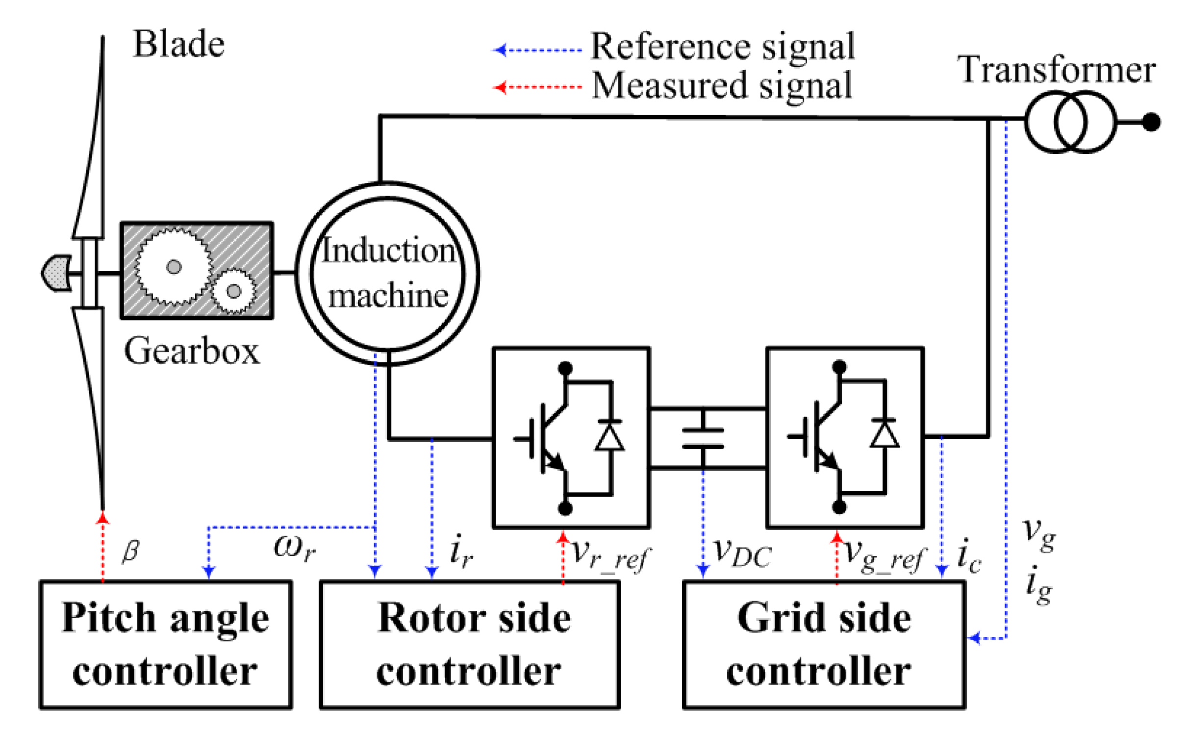
Figure 1, the DFIG control system includes a pitch angle controller, a rotor-side controller, and a grid-side controller. The pitch angle controller focuses on preventing
ωr from the maximum
ωr and enables the de-loading operation according to the order from the high level controller. The rotor- side controller, which realizes the decoupled control of reactive and active powers, is used for keeping the voltage of stator at the reference value and to regulate the active power fed to the power grid. The gird-side controller regulates the DC-link voltage in this study.
As represented in [
18], the MPT operation power reference (
PMPT) is provided by:
where
cP, max indicates the maximum value of
cP and is set to 0.5;
λopt is the optimal value of
λ and is set to 9.95;
kg is set to 0.512.
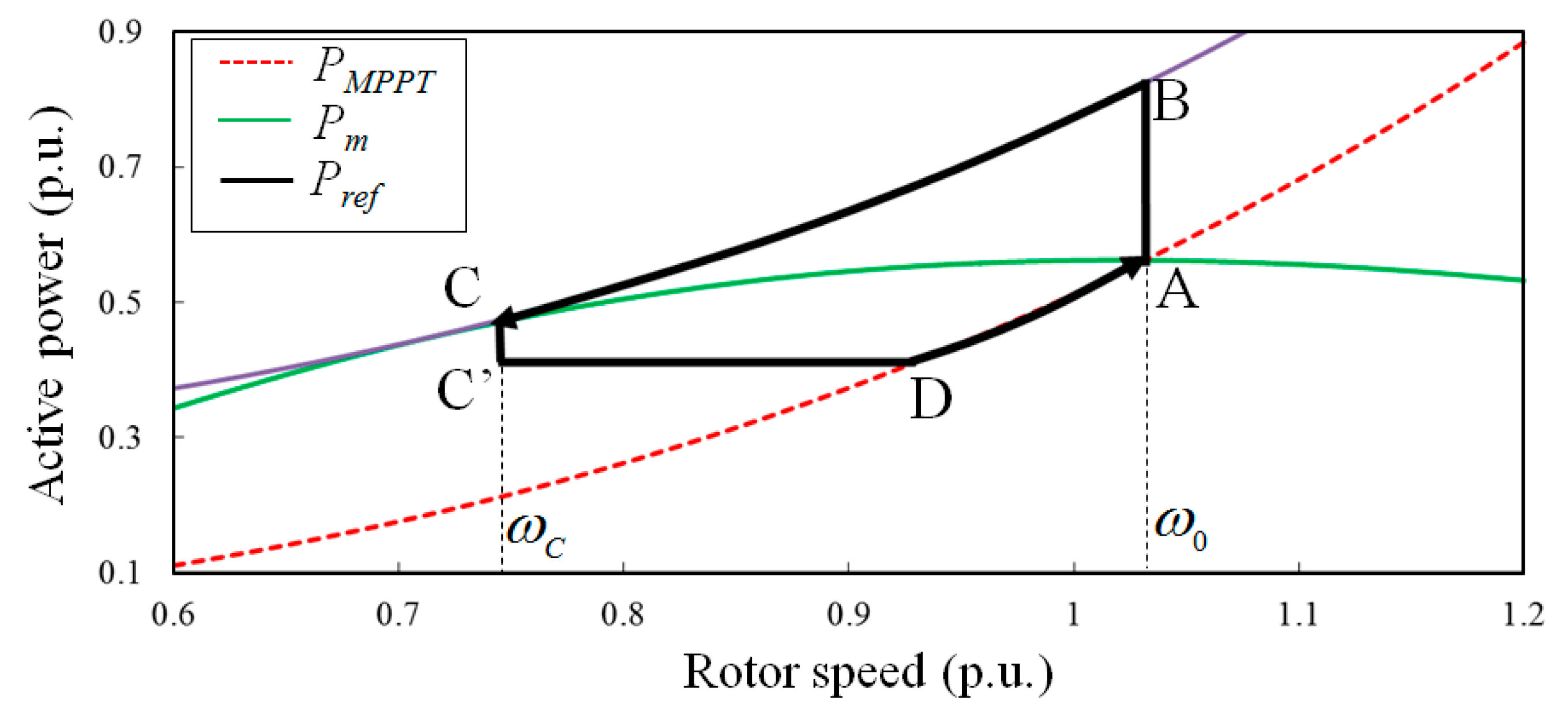
As shown in
Figure 2, the red dotted line indicates
PMPT. The greed solid lines represent different mechanical power curves for various wind speeds.
4. Short-Term Frequency Support of a DFIG
To heighten the system frequency nadir, STFS methods release the rotating kinetic energy stored in DFIGs. During the deceleration period, the rotor speed decreases because the output power of DFIGs, Pe, is greater than the mechanical input power, Pm. STFS methods should prevent stall of the rotor speed. To restore the rotor speed to the optimal value, ω0, STFS methods decrease Pe, which should be less than Pm. The time for the rotor recovery depends on the difference between Pe and Pm.
The following subsection describes the concepts of the conventional STFS method and proposed STFS method, respectively.
4.1. Conventional Short-Term Frequency Support Method of a DFIG
To heighten the system frequency nadir while preventing the rotor speed from stalling, Pref in this method includes deceleration and acceleration periods. In the deceleration period and the acceleration period, Pref is defined in the rotor speed domain and in the time domain, respectively.
4.1.1. Power Reference in the Deceleration Period of Short-Term Frequency Support Method
In the deceleration period,
Pref for STFS method,
PSTFS, is determined as:
where Δ
Pcon is the incremental power of the conventional method and is proportional to the rotor speed, as explained in [
12].
To heighten the system frequency nadir, Δ
Pcon is added to
PMPT, as shown by the locus from Point A to Point B (see in
Figure 3). Afterward,
PSTFS reduces with the rotor speed, as shown by the locus from Point B toward Point C; thereafter,
PSTFS meets the
Pm curve, and then
ωr converges at Point C so that this method can prevent the stall of the DFIG. Nevertheless, during this period, the difference between
Pm and
Pe becomes small as the rotor speed decreases, especially when the rotor speed is closed to
ωc, which is the rotor speed at Point C in
Figure 3. As a result, this method delays the rotor speed convergence, thereby releasing more rotating kinetic energy to the grid after supporting the system frequency.
4.1.2. Power Reference in the Acceleration Period of Short-Term Frequency Support Method
At Point C in
Figure 3, the deceleration period ends and the acceleration period begins. To recover the rotor speed to
ω0, this method decreases
PSTFS from
PSTFS(
ωc) to
PSTFS(
ωc) − 0.03 p.u. and then maintains this value until
PSTFS intersects
PMPT at Point D. Thereafter, the rotor speed is restored to
ω0 with the MPT curve. Even though this method can guarantee a lesser SFD, it delays the rotor speed restoration, thereby capturing less mechanical energy from the wind because
Pm varies with the rotor speed.
4.2. Proposed Short-Term Frequency Support Method of a DFIG
The objectives of this study are to (1) provide the approximate performance of improving the frequency nadir with less released energy from a DFIG compared to the conventional method and (2) speed up the restoration of the rotor speed. As in the conventional method, the proposed PSTFS consists of two periods: deceleration and acceleration periods. Unlike in the conventional method, the used incremental power for STFS is a function of the rotor speed in the deceleration period, and PSTFS is a function of the rotor speed and time in the acceleration period.
4.2.1. Power Reference in the Deceleration Period of Short-Term Frequency Support Method
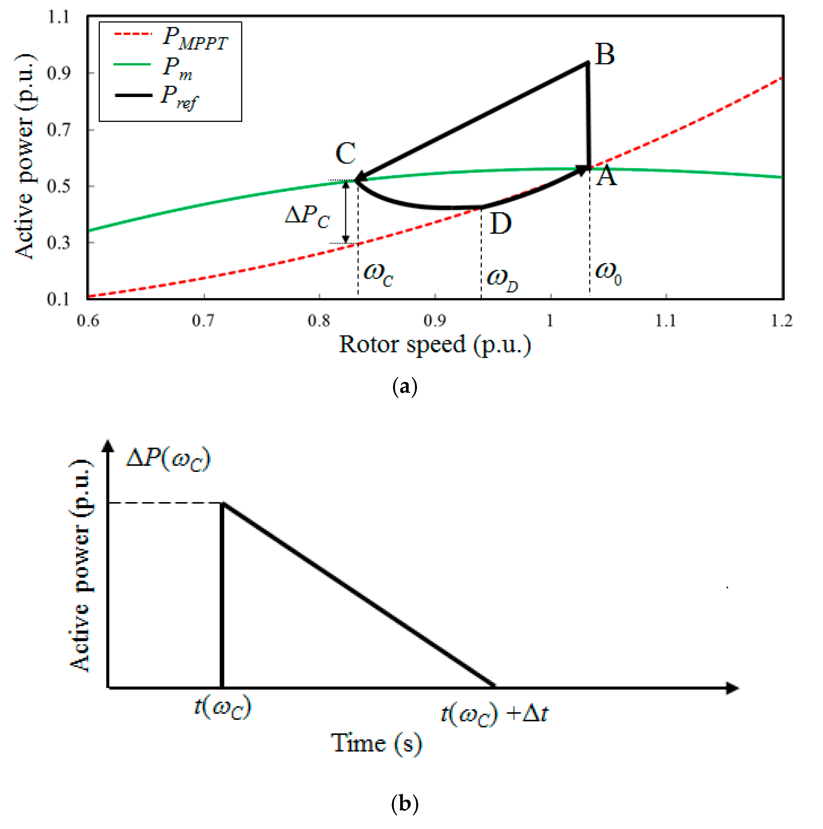
To provide the approximate performance of frequency nadir improvement with less released energy from a DFIG,
PSTFS is defined as:
where Δ
Ppro is the incremental power of the proposed method and is a function of Δ
Pcon and the rotor speed;
ω0 and
ωmin are the rotor speed prior to disturbance and minimum value of the rotor speed, respectively.
Note that Δ
Ppro in the proposed method varies with the rotor speed, whereas Δ
Pcon in the conventional method is fixed during the deceleration period. As indicated in Equation (13), Δ
Ppro equals to Δ
Pcon at instant of
t0 because the value of the rotor speed is the same as
ω0. As the rotor speed decreases, Δ
Ppro decreases until
Pe =
Pm at Point C (see in
Figure 4). As a result, the power injection in the proposed method during the beginning stage of a disturbance is slightly smaller than the conventional strategy. Thus, the proposed strategy can provide the approximate performance of the system frequency nadir improvement. As a comparison between
Figure 3 and
Figure 4a,
Pm –
Pe rapidly reduces to zero compared to the conventional strategy. This is because the second part of Equation (13) leads
Pe to rapidly intersect
Pm curve. Accordingly, the rotor speed for the proposed method rapidly converges to
ωc, which is higher than that of the conventional strategy. Hence, less rotating kinetic energy is released after supporting the system frequency during the deceleration period.
4.2.2. Power Reference in the Acceleration Period of Short-Term Frequency Support Method
To restore the rotor speed of DFIGs, the conventional method in [
12] decreases its output power by 0.03 p.u. in a step-like manner after the rotor speed converges to Point C. With various settings of the reduced power, the time of the rotor speed restoration and size of SFD become different. This means that the output power decrease of more than 0.03 p.u. is advantageous for fast rotor speed restoration; meanwhile, it might act as a severe SFD after decreasing
Pref to Point C. For speeding up the rotor speed restoration with a small SFD, a large power reduction from Point C should smoothly decrease. To this end,
PSTFS in the proposed method smoothly decreases during Δ
t from the locus Point C to Point D (see in
Figure 4), as defined in Equation (14). From Point D,
ωr returns to
ω0 along with the MPT curve, as in the conventional method.
where Δ
p(
ωC) is
PSTFS(
ωc) −
PMPT(
ωc);
t(
ωc) is the beginning of the acceleration period; and Δ
t is the duration from Point C to Point D (see in
Figure 4a).
As in Equation (14), the first part—which is cube of
ωr—increases with
ωr; the second part decreases with time and decreases to zero at
t(
ωc) + Δ
t (Point D in
Figure 4a). Thus, the performance in terms of the duration for the rotor speed restoration and size of an SFD critically relies on the setting of Δ
t. If the value of Δ
t is close to zero, the recovery of the rotor speed is significantly rapid, but it leads to a severe SFD because of the rapid output decrease from the trajectory Point C to Point D in
Figure 4a, and vice versa. Special attention should be paid to setting the value of Δ
t.
In this study, as a comparison, the value of Δt is set to a value so that the second frequency deviation in the proposed method is the same as in the conventional method. Note that Δt can be set to other values depending on the design objectives; to minimize an SFD, Δt can be set to a value as large as possible or to accomplish the rapid rotor speed recovery, Δt can be set to zero. However, this is out of the scope of this study.
5. System Layout
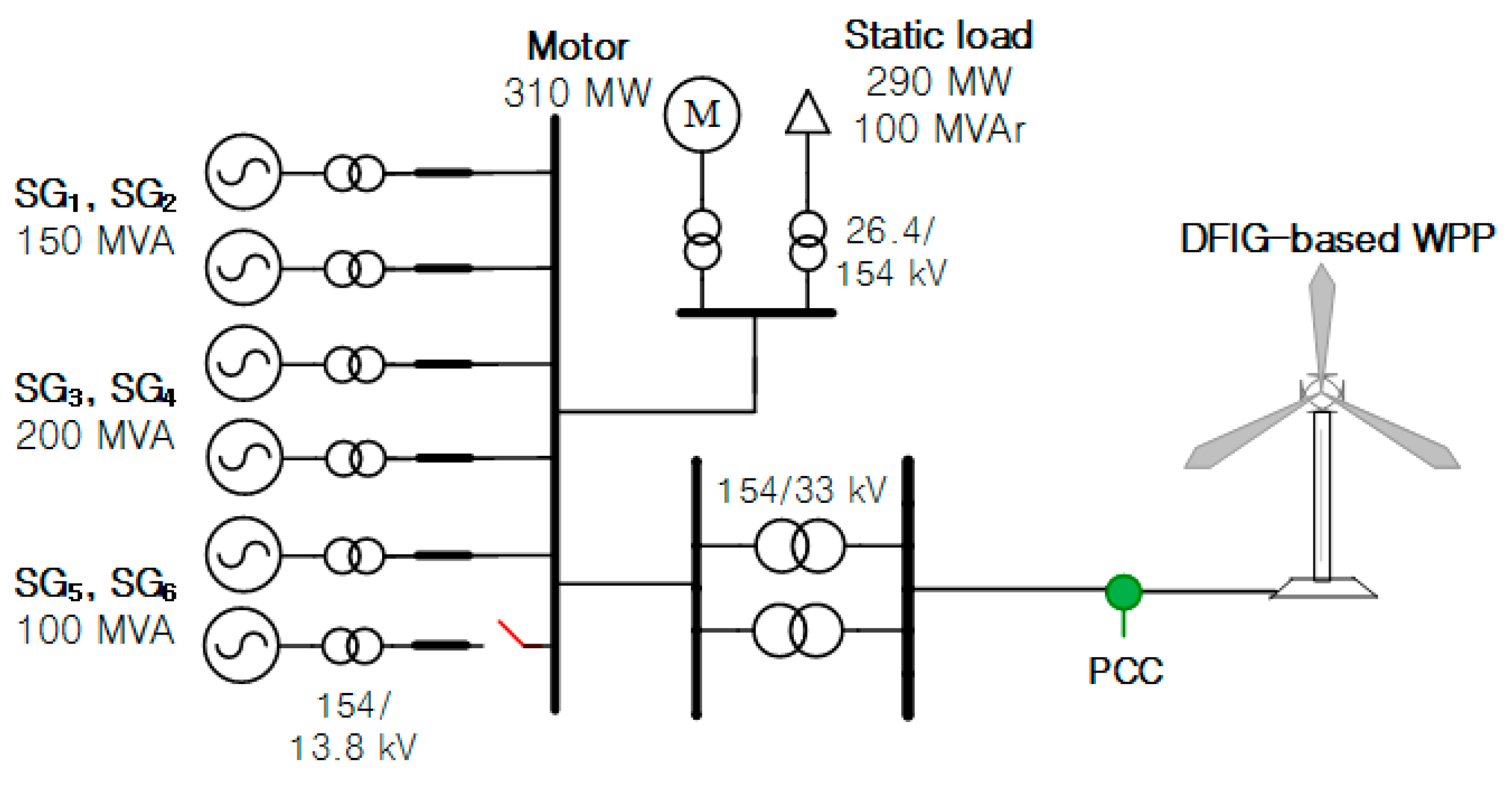
Dynamic simulations are conducted to investigate the performances of the proposed STFS strategy from a DFIG, as shown in
Figure 5. The test power system comprises six synchronous generators, an aggregated DFIG-based wind power plant with 100-MW installed capacity, and motor and static loads.
The detailed parameters of synchronous generators are shown in
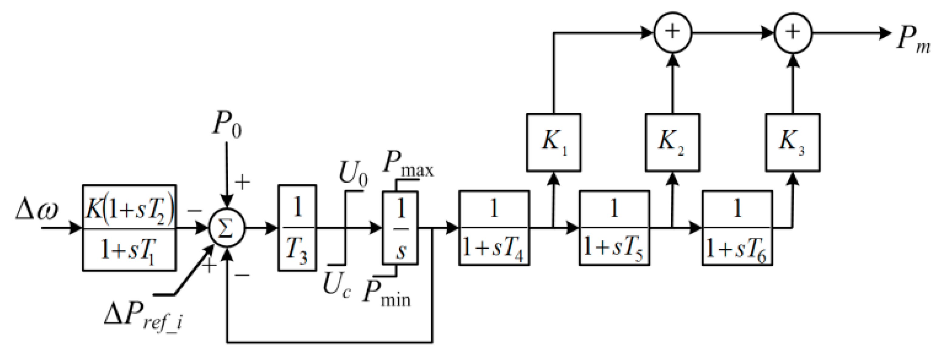
Table 1. All synchronous generators are assumed to be the IEEEG1 steam governor model with tandem-compound, single-reheat (type B) [
19]. IEEEX1 is selected for voltage control. In addition,
Figure 6 displays the IEEEG1 steam governor model and
Table 2 presents its coefficients. Note that the secondary frequency control is not considered, therefore the frequency will not return to the nominal value.
The stable
ωr operating range of the DFIG is from 0.7 p.u. to 1.25 p.u. The inertia constant for the DFIG is 5.0 s. The settings of power limit and torque limit are 1.1 p.u. and 0.88 p.u., respectively. Furthermore, the setting of the rate limit of power is 0.45 p.u./s [
20]. The detailed parameters of the DFIG are presented in
Table 3.
6. Dynamic Simulation Results
In this section, simulation scenarios on different wind speeds are carried out to investigate the performances of the proposed strategy. As disturbance, SG6 generating 70.0 MW is tripped at 10.0 s.
The metrics of the system frequency nadir, second frequency nadir, nadir-based frequency response, captured mechanical power, released rotating kinetic energy (ΔErel), and time for the ωr restoration for the proposed strategy are compared in the conventional method and the MPT operation.
Among them, the nadir-based frequency response (NBFR), which is one of the system frequency response metrics for assessing the rigidness of an electric power grid, is presented as in [
21].
where
Ploss indicates the loss of power generation and is 70 MW in this study.
fn and
fmin are the nominal frequency and the minimum frequency during a disturbance, respectively.
According to Equation (15), NBFR signifies that a loss of active power generation required for causing 1.0 Hz frequency decline. Accordingly, the electric power grid with a large NBFR is capable of guaranteeing the frequency stability during a disturbance.
The released kinetic energy (Δ
Erel) can be calculated by:
where
HDFIG means the inertia constant of a DFIG, which respectively comprises the inertia constants of an induction generator and a wind turbine.
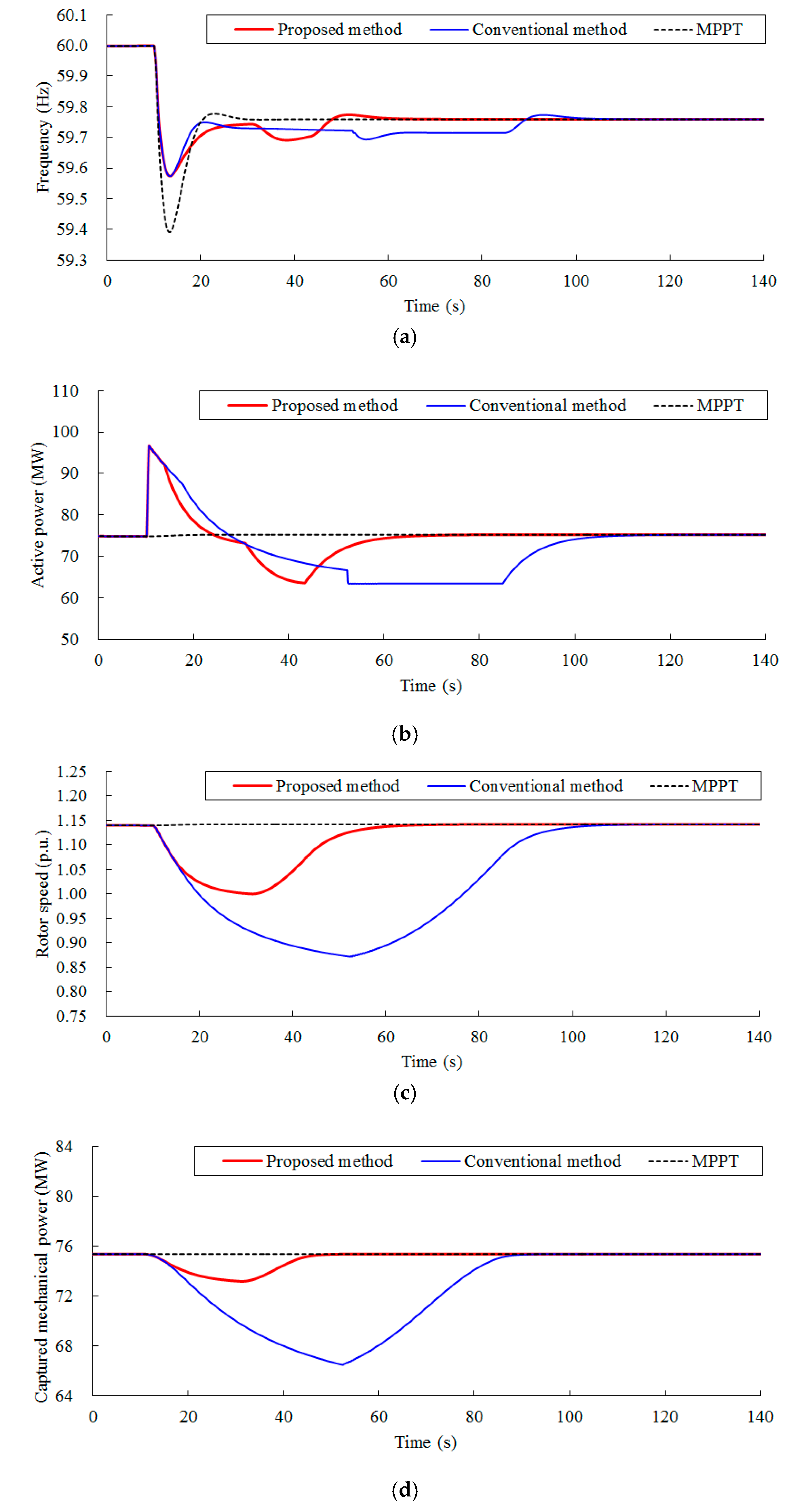
6.1. Case 1: Wind Speed = 10.0 m/s
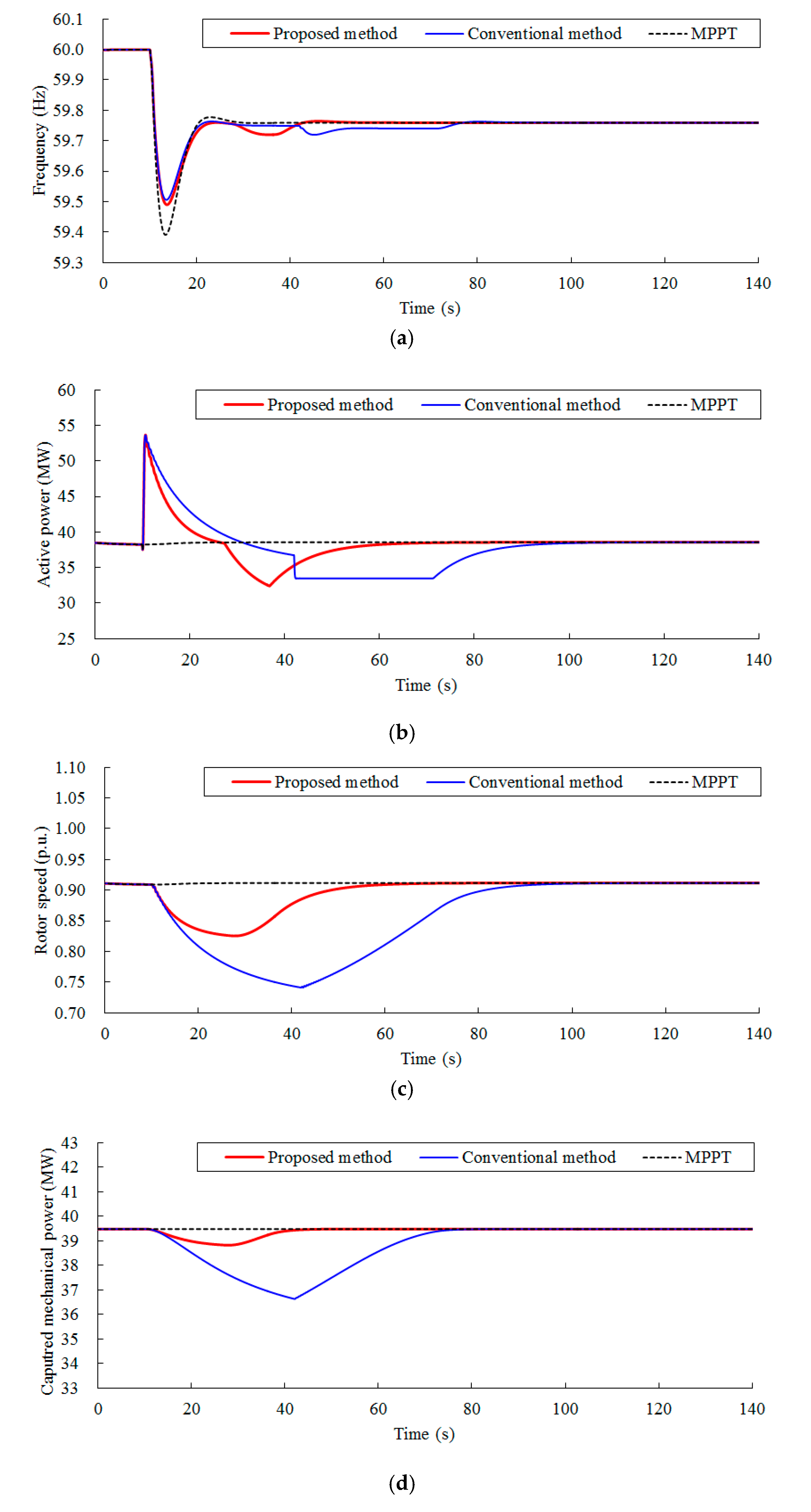
Figure 7 presents simulation results for Case 1 (the incoming wind speed of the DFIG is 10.0 m/s). The rotating kinetic energy available is 4.041 s. In the conventional method, Δ
Pcon is 0.34 p.u. and the setting of
ωc is 0.87 p.u. In addition, the setting of Δ
t in the proposed method is 12.5 s.
As shown in
Figure 7a, the system frequency nadirs for MPT, the conventional method, and the proposed method, respectively, are 59.391 Hz, 59.574 Hz, and 59.574 Hz. The system frequency nadir of the proposed method is the same as in the conventional method due to the same output power from a DFIG (which is limited by the torque limit), as in
Figure 7b. The NBFR in the proposed method is 164.3 MW/Hz, which is the same as in the conventional strategy because of the identical system frequency nadir. The second frequency nadirs for the proposed method and the conventional method are the same (59.693 Hz). This is because Δ
t is set to 12.5 s so that the second frequency deviation in the proposed strategy is the same as in the conventional strategy.
Due to the second part of Equation (13),
ωr rapidly converges to 1.00 p.u. at 31.4 s, as shown in
Figure 7c. However, the rotor speed in the conventional method converges to 0.87 p.u. at 52.7 s, which is slower than in the proposed method by 21.3 s. Thus, the proposed method starts recovering
ωr earlier than in the conventional strategy. Moreover, the rotating kinetic energy cost in the proposed method is 1.491 s, which is significantly less than in the conventional method due to the high
ωc.
During the deceleration period, the released rotating kinetic energy around the system frequency nadir for the proposed strategy is 0.583 s, which is the same as in the conventional method (see
Figure 7c); however, the released rotating kinetic energy in the rest acceleration period is 0.908 s, which is 0.43 times greater than that of the conventional strategy. Thus, after supporting the system frequency nadir, the proposed strategy releases the rotating kinetic energy significantly less than in the conventional strategy.
As displayed in
Figure 7c, when the proposed method produces the same second frequency deviation as in the conventional method, the rotor speed in the proposed method is recovered at 72.2 s, which is 41.7 s faster than the conventional method because of less released kinetic energy, rapid rotor speed convergence, and the power reference in Equation (14). Furthermore, the harvested mechanical input power from 10.0 s to 110.0 s in the proposed strategy is 6.96 MWh, which is 0.29 MWh more than in the conventional strategy. This is due to less released rotating kinetic energy and rapid rotor speed recovery.
6.2. Case 2: Wind Speed = 8.0 m/s
Figure 8 displays simulation results for Case 2 (the incoming wind speed of the DFIG is 8.0 m/s) and is smaller than in Case 1 by 2.0 m/s. Thus, the available kinetic energy from a DFIG is 1.683 s, which is 38.2% of that available in Case 1. Accordingly, Δ
Pcon is 0.16 p.u., which is smaller than in Case 1.
Ωc in the conventional strategy is set to 0.74 p.u. In addition, Δ
t in the proposed method is set to 9.5 s.
The system frequency nadir for MPT is 59.391 Hz, which is the same as in Case 1 because no power is injected from a DFIG and all active power is compensated by synchronous generators. The system frequency nadir for the proposed strategy is 59.490 Hz, which is slightly smaller than that of the conventional strategy. This is because the output power rapidly decreases during the deceleration period and is slightly smaller compared to that of the conventional strategy, around 13.0 s (see
Figure 8b). In addition, the system frequency nadirs for the proposed and conventional methods are less than those in Case 1 due to less incremental power for STFS.
Similar to Case 1, in the proposed strategy, the second frequency deviation, which indicates the difference between the second frequency nadir and the nominal frequency, is 0.280 Hz, which is the same as in the conventional method because of the setting of Δ
t in Equation (14) (see
Figure 8a). In addition, the NBFR in the proposed strategy is slightly smaller compared to the conventional strategy due to the lower system frequency nadir in the proposed strategy.
The rotor speed in the proposed method converges to 0.83 p.u. at 29.9 s; whereas, the rotor speed in the conventional method converges to 0.74 p.u. at 42.0 s. Accordingly, the proposed method starts recovering
ωr 12.1 s earlier than in the conventional method, as in the previous case (see
Figure 8c). Consequently, as shown in
Table 4, the released rotating kinetic energy for the proposed strategy is 0.730 s, which is 52.5% of the released rotating kinetic energy for the conventional strategy.
The released rotating kinetic energy around the system frequency nadir in the proposed strategy is 0.373 s in the deceleration period, which is slightly smaller than in the conventional strategy by 0.043 s; nevertheless, the released rotating kinetic energy in the rest acceleration period is 0.373 s, which is 0.614 s less than in the conventional strategy. After supporting the system frequency, the proposed strategy releases rotating kinetic energy significantly less than in the conventional method.
As in Case 1, when the proposed strategy produces the same second frequency deviation as the conventional method, the rotor speed restoration duration in the proposed strategy is 93.0 s, which is 29.5 s faster than in the conventional strategy. Furthermore, the harvested mechanical input power during 100.0 s in the proposed strategy is 3.58 MWh, which is 0.07 MWh greater than in the conventional strategy.
Simulation results of two cases clearly represents that the proposed strategy can provide approximate performance of the system frequency nadir with less released rotating kinetic energy from a DFIG under different wind speeds; particularly, after supporting the frequency nadir, the proposed strategy releases rotating kinetic energy significantly less than in the conventional strategy. The proposed strategy accelerates the restoration of the rotor speed when it results in the same second frequency deviation compared to the conventional method during STFS. Moreover, the proposed restoration captures more mechanical input power than in the conventional method. Hence, the proposed restoration effectively employs the rotating masses of DFIGs for STFS.
7. Conclusions
This paper suggests an enhanced STFS method of DFIGs for preserving the better performance of improving the system frequency nadir with less released rotating kinetic energy and accelerating the recovery of the rotor speed. To this end, a rotor speed-dependent incremental power is proposed in the deceleration period; in addition, the active power reference of the proposed STFS smoothly decreases with time and rotor speed until the power reference reaches the MPT curve during the acceleration period.
Simulation results on different wind speeds demonstrate that the proposed strategy provides the approximate performance of improving the system frequency nadir with less rotating energy cost during the deceleration period compared to the conventional method; furthermore, with the same size of the second frequency deviation in the proposed method and the conventional method, the proposed method is capable of accelerating the rotor speed recovery during the acceleration period, thereby capturing more mechanical input power during STFS. Accordingly, the proposed strategy effectively employs the rotating masses of DFIGs for system inertia support after a disturbance to improve the power grid resilience.


