Abstract
Fabric-reinforced cementitious composites are a recent family of commercial products devoted to the external retrofitting and strengthening of masonry and concrete structures. In the present work, the authors investigate the possibility of using, as matrix, a mortar based on alkali-activated materials. Basalt textile was selected as reinforcement because it is an effective, low-cost and environmentally friendly reinforcement. The matrix was prepared using by-products of industrial processes. Mortar was characterized by measuring its drying shrinkage, capillary water absorption, compressive and flexural strengths and analyzed using X-Ray diffractometry, Fourier-transform infrared spectroscopy, and thermogravimetric analysis. The mechanical behavior of the composites was investigated through tensile and direct shear tests. The basalt fabric-reinforced alkali-activated matrix composite showed, under tension, a tri-linear response curve, mainly governed by cracks development and widening. The measured ultimate stress, ultimate strain and tensile modulus of elasticity in region III were 434 MPa (CoV 14.2%), 2.192% (CoV 4.1%) and 39 GPa (CoV 11.3%), respectively. The load–global slip response curves of the composite show an average peak load around 1148 N (CoV 23.0%) and an exploitation ratio versus the textile and the tensile of 0.40 and 0.86, respectively. Even if the preliminary results are encouraging, the performance of FRAAM composites would be positively affected by an increase of the dimensional stability of the matrix.
1. Introduction
In recent decades, significant improvements in the technologies and products available for the external strengthening and retrofitting of historical masonry structures and more recent structural elements have been developed. The first marketed family of products, Fiber Reinforced Polymer (FRP) composites, had fast and facile installation procedures, were lightweight, and showed good strengthening properties [1,2]. Despite the indisputable advantages described above, FRPs soon revealed relevant drawbacks, such as, among other things, low compatibility with the stringent requirements implemented for protecting buildings that are part of cultural heritage, installation problems in the presence of wet surfaces, and low thermal and fire resistance [3,4,5]. Thus, a second generation of products, based on fabric embedded in an inorganic matrix (cement or lime-based mortars), was formulated. These are referred as Fabric-Reinforced Cementitious Matrix composites (FRCM), Textile-Reinforced Mortars (TRM), Cementitious Matrix-Grid (CMG), and Inorganic Matrix-Grid (IMG) composites [6]. Extensive experimental and theoretical research activities have been carried out and are still in progress to investigate and validate the mechanical behavior and bond properties of carbon fabric-cement-based mortar composite [3], polyparaphenylene benzobisoxazole (PBO) fabric-cement-based mortar composite [7,8], glass grid-cement-based mortar composite [9], and unidirectional steel textile-cement-based/mineral-based mortar composite [10]. The general outcomes of these investigations confirmed that textile geometry, sand granulometry, mechanical properties of the constituent materials and their combination affect the load-bearing capacity, bond strength on substrate, and failure modes of FRCM composites. Furthermore, various experimental campaigns [11,12] have pointed out that tensile and shear bond tests on FRCM composites are relevant in delivering reliable design methodologies.
Several recent papers have investigated the performance of basalt FRCM composites for retrofit applications on masonry. Lignola et al. [13] tested different basalt-based FRCM configurations comprising readily available commercial systems. Basalt textiles with a yarn spacing of 25 mm and area weights of 220 or 350 g/m2 were embedded in a one component mortar containing redispersable polymers or a natural hydraulic lime mortar, and basalt textiles with a yarn spacing 6 mm and an area weight of 250 g/m2 were embedded in a two components mortar containing hydraulic lime, Eco-Pozzolan, special additives and synthetic polymers in water dispersion. Performance was evaluated in terms of both uniaxial tensile behavior and bond to masonry. The outcomes of the investigation revealed that the tensile tests were repeatable and reproducible in terms of peak stress, but matrix properties and fiber slippage caused some of them to fail in showing the expected trilinear behavior, whereas bond tests resulted in quite uniform peak stress.
Iorfida et al. [14] investigated the mechanical performances of a commercial basalt-FRCM system based on a basalt textile with an area weight of 400 g/m2 and a yarn spacing of 8 mm embedded in a mineral-natural hydraulic lime mortar. Tensile tests and single-lap shear tests on masonry substrate were carried out to study the mechanical behavior and the bond properties of the composite. The tensile behavior of basalt-FRCM system was characterized by a tri-linear stress–strain response with failure occurring by sequential tensile failure of the fiber bundles. In single-lap shear tests, failure was characterized by the detachment of the fabric strips and external matrix layer.
For more than seven decades now [15,16,17,18], a broad family of binders, the alkali-activated materials, has been attracting systematic and increasing academic interest and has found large-scale applications in Eastern Europe and China [19,20]. A multitude of reactive powders obtained from natural sources, industrial by-products and alkaline activators can be used for their production. The nature and content of the alkaline activators as well as the variability in the composition and reactivity of the raw materials impact the development of the mechanical and the fresh state properties, the shrinkage behavior and the durability of the produced mortars or concrete. When amorphous aluminosilicate reactive powders, such as metakaolin and fly ash, are used, strong alkaline activator solutions and mild temperatures are necessary to activate the powders. The so-obtained binders are geopolymers. They can be considered as the amorphous analogue of zeolites and are characterized by a higher initial alkalinity, the formation of an amorphous sodium aluminosilicate hydrate gel (N–A–S–H) and the absence of lime as reaction product [21,22,23]. They can find application in structures exposed to high temperatures or chemical attacks. When granulated blast furnace slag (GGBFS) is used, milder process conditions can be adopted and the main hydration product is a calcium aluminosilicate hydrate (C–A–S–H) gel. Finally, several works have investigated the hybrid or blended alkali-activated materials (AAM), which are a combination of the previously described systems and could provide improved mechanical and durability properties and a better tuning of the fresh properties [24,25].
Recently, some authors have investigated the use of steel fiber-reinforced geopolymer matrix (S-FRGM) composites for external strengthening applications [26]. The initial highly alkaline environment, required for the geopolymerization to start, resulted in having a detrimental effect on composite performance by weakening the interaction between matrix and fibers, when not carefully tuned.
The aim of this work is to overcome the issues observed when geopolymeric mortars are used in fiber-reinforced geopolymer matrix composite when still using a binder with improved resistance to fire and high temperatures, a higher resistance to sulfate attack than the one provided by Ordinary Portland Cement (OPC) and lime matrices [27,28,29,30,31,32,33].
The mortar, based on hybrid alkali-activated binder and containing only industrial by-products as reactive powders, was characterized by measuring drying shrinkage, capillary water absorption, compressive and flexural strengths and analyzed using X-Ray diffractometry (XRD), Fourier-transform infrared spectroscopy (FT-IR) and thermogravimetric analysis (TGA). The mortar was then used as matrix to manufacture basalt fabric-reinforced alkali-activated matrix (FRAAM) composites.
A commercial balanced, coated, bidirectional fabric made out of basalt fibers was used as reinforcement.
Composites were characterized through direct shear tests carried out on brickwork substrates using an externally bonded FRAAM composite strips and tensile tests. Their mechanical behavior was compared with that exhibited by an available commercial system based on the same basalt textile [14].
2. Materials and Methods
2.1. Matrix Raw Materials
2.1.1. Ultra-Fine Fly Ash (FA)
Fly Ash compliant with ASTM C618 class F was used in the experimental campaign. Its particle size distribution was characterized by a D10 of 0.5 μm, a D50 of 5 μm and a D90 of 11 μm. Its chemical composition, expressed on weight basis and in terms of oxide was mainly constituted by SiO2 = 53.5%, Al2O3 = 34.3%, Fe2O3 = 3.6% and CaO = 4.4%.
2.1.2. Ground Granulated Blast Furnace Slag (GGBFS)
Ground granulated blast furnace slag having a D10 of 6.76 μm, a D50 of 18.5 μm and a D90 of 33.17 μm complying with European standard NF EN 15167-1, 2006 was used in the experimental campaign. Its chemical composition, in terms of oxides and obtained by Energy Dispersive X-ray analysis (EDX), was mainly constituted by SiO2 = 36.13%, Al2O3 = 10.19%, K2O = 0.69%, MgO = 6.72% SO3 = 1.75% and CaO = 43.04%.
2.1.3. Forest Biomass Ash (FBA)
Forest biomass ash having a D10 of 11.72 μm, a D50 of 30.16 μm, and a D90 of 61.47 μm was provided by a local thermal power plant. Its chemical composition, expressed on weight basis and in terms of oxide was mainly constituted by SiO2 = 23.5%, Al2O3 = 17.5%, K2O = 7.1%, Na2O = 4.3, Fe2O3 = 7.5%, CaO = 9.8%, C = 10% and N = 8.5%.
2.1.4. Alkaline Activators and Additives
Potassium hydroxide with a purity of 85% and sodium trisilicate, in powder form, with a composition on weight basis of Na2O ≥ 18% and SiO2 ≥ 60%, were used as alkaline activators.
Calcium oxide with a density of 3 g∙cm−3 and a residue on 75 µm of 5–20% by weight was used as additive.
2.1.5. Sand
A commercial siliceous sand, with particles size distribution between 0.1–1 mm was used in the experimental campaign. Its gradation curve, reported in Figure 1, was determined by sieve analysis carried out by the authors.
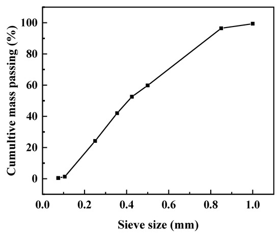
Figure 1.
Sand gradation curve.
2.2. Methods
2.2.1. Matrix Mix Design and Preparation
A hybrid alkali-activated binder containing GGBFS, FA and FBA as reactive powders was used as matrix for the composite. The water/(reactive powders + alkaline activators) and sand/(reactive powders) weight ratios were respectively fixed at 0.53 and 2.7 to produce the alkali-activated matrix. Its composition, in terms of reactive powders, alkaline activators and additives, is reported in Table 1.

Table 1.
Mortar mix design.
In the conventional two-part alkali-activated materials (AAM), the alkali activation process involves the addition of concentrated aqueous alkaline solutions, which are corrosive, viscous, difficult to handle and not user friendly to the reactive powders. Consequently, the development of so-called one-part or “just add water” AAMs may have greater potential than the conventional two-part AAMs, especially in cast-in situ applications. One-part AAM involves a dry mix that consists of a solid calcium-alumino-silicate precursor, a solid alkali source and possible admixtures to which water is added. This is considered a relevant commercial driver for their marketing, because the use of concentrated aqueous alkali solutions is avoided and the preparation process is similar to that of OPC-based mortars [34,35]. A one part approach was used to prepare the matrix. The solid alkaline activators, additive and the reactive powders were dry mixed for 5 min to homogenize the composition of the blend. Water was then added, and the mixture was mixed for 10 min. Finally, sand was added, and the fresh mortar was mixed for a further 5 min.
2.2.2. Matrix Characterization
The reaction products were analyzed by X-Ray Diffractometry at 2, 7 and 28 day of curing, by thermogravimetric analysis and by FT-IR Spectroscopy.
Drying shrinkage measurements of mortar mix have been carried out according to relevant standard EN 12617-4 on prismatic specimens with dimension of 40 × 40 × 160 mm at 21 ± 1 °C and a humidity (HR) 60 ± 10%.
Capillary water absorption tests were carried out according to EN 1015-18. The specimens were dried in a ventilated oven at 50 °C until a constant mass has been achieved. After cooling at 20 °C, all of the specimens were put on supports in a shallow bath of water a 20 °C, at a depth of about 5 mm. The uptake of water by capillary absorption was measured through the weight gain of each specimen at regular intervals of immersion. The equation used to model the absorption of water due to capillary action was the following:
where A (g/mm2) is the water absorption by unit area since the dipping in water, S (g/(mm2 × min0.5)) is the sorptivity of the material, t is the elapsed time in minutes, and a0 (g/mm2) is the water initially absorbed by pores in contact with water [23].
A = a0 + S t0.5
Compressive and flexural strengths were determined on prismatic specimens with dimensions of 40 × 40 × 160 mm after 2, 7 and 28 days of curing according to EN 1015-11. All the values were obtained as the average of three tested specimens.
2.2.3. Reinforcement Characterization
A balanced, coated, bidirectional fabric made out of basalt fibers was selected as reinforcement. ASTM D3039 was used to investigate the mechanical properties of the fabric. Tensile tests were carried out on six specimens having a length of 500 mm and a width of 50 mm. Aluminum smoothed tabs with a thickness of 3 mm, bonded to the edge of each specimen for a length of 70 mm, provided a uniform load distribution.
Tests were performed in displacement control at a rate of 1.25 mm/min and strain was measured using an extensometer having 50 mm gage length, installed in the center of the specimen. Stresses were then calculated using the recorded load F, divided by cross-section area of the fabric reinforcement Af as per Equation (2):
where:
σ = F/Af with Af = teq × beff, beff = by × ny
- teq is the equivalent design thickness of the fabric,
- beff is the nominal specimen width,
- by is the mid-yarn spacing (normal to the load application direction)
- ny is the number of longitudinal yarns.
Textile tensile tests were carried out by the authors on six specimens and the obtained stress–strain response curves are shown in Figure 2.
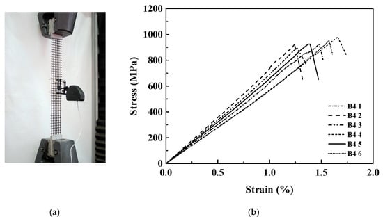
Figure 2.
(a) Scheme of the tensile test; (b) stress–strain response curves of textile specimens under tension.
The main physical and measured mechanical properties of the textile are summarized in Table 2. Nearly simultaneous rupture of the fiber bundles was observed as failure mode of the tested samples.
Table 2.
Physical and mechanical properties of the textile.
2.2.4. Strengthening System Characterization: Tensile Test
Five specimens with nominal dimensions of 500 mm × 50 mm × 10 mm and containing six embedded rovings at mid matrix thickness and in the loading direction were used to carry out the tensile tests. Before testing, specimens were cured at 20 °C and 95% R.H. for 28 days. 3 mm thick and 100 mm long bonded aluminum tabs, provided a uniform load distribution and avoided mortar crushing in the gripping areas. Tensile tests were carried out using wedge type grip under machine stroke control at a rate of 0.25 mm/min. The clamped area was 80 mm long. Strain measurements, in the gauge length, were acquired by two Linear Variable Displacement Transducers (LVDT a and b), which were fixed lengthwise by means of suitably designed aluminum supports [14]. The tensile test set up is reported in Figure 3a.
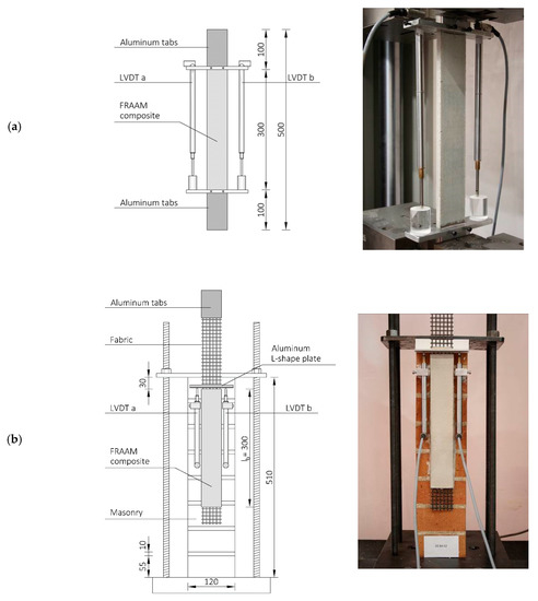
Figure 3.
Test setup: (a) tensile test scheme and (b) single-lap shear test (dimensions in mm).
2.2.5. Strengthening System Characterization: Direct Shear Test
Six FRAAM composite strips externally bonded on brickwork substrate were used to carry out direct shear tests. Masonry prisms were produced by stack-bonding eight half bricks with 10 mm thick mortar joints. Modern clay bricks, with compressive strength equal to 42 MPa (CoV 5.26%) measured according to EN 772-1, and a M5 lime mortar were used. Nominal dimensions of prisms were 120 mm × 120 mm × 510 mm. The 300-mm-long and 50-mm-wide FRAAM composite strips, bonded to the 120 mm × 510 mm prism face, as reported in Figure 3b, were produced by embedding fabric at the mid matrix thickness, allowing some fabric to be left bare outside beyond the loaded and unloaded edge. Specimens were moist-cured for 7 days and then stored in laboratory conditions for 21 days until testing. Single lap direct shear tests were then carried out to study the shear debonding of FRAAM to masonry substrate. The bare fabric on the top edge, after being bonded to aluminum tabs, was pulled up being the masonry prism restrained to the testing machine base using a steel plate and four bolts. Two LVDTs were installed on the masonry surface next to the loaded edge of the FRAAM composite. They reacted off of a thin aluminum L-shape plate glued to the first transversal fiber bundle outside the bonded area. The global slip s was defined as the average of the two LVDTs readings. Tests were performed under machine stroke control at a rate of 0.18 mm/min and test data were logged with a sampling frequency of 5 Hz [14]. The surface of the masonry prisms was roughened to promote adhesion of FRAAM composite. The single-lap shear test set up is reported in Figure 3b.
3. Results and Discussion
3.1. Matrix
Figure 4 shows the X-ray diffractograms of the pastes obtained by alkaline activation of the reactive powders blend after 2, 7 and 28 days of curing at 20 °C.
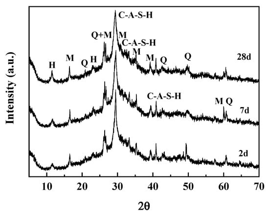
Figure 4.
X-Ray diffractograms of pastes after 2, 7 and 28 days of curing; M = Mullite; Q = quartz, H = Hydrotalcite.
The main crystalline phases identified are aluminum containing C–S–H (C–A–S–H) (PDF 00-034-0002), Mullite (PDF 00-006-0259), Quartz (PDF 00-001-0649) and Hydrotalcite (PDF 01-089-5434). Quartz and Mullite are impurities of the reactive powders. Being crystalline phases, they do not participate in the alkaline activation and can be found unaltered among the final products. The main reaction products of the alkaline activation are the C–A–S–H and the Hydrotalcite [36,37]. Hydrotalcite is commonly detected when a high degree of slag hydration is reached, and slag contains a sufficient amount of Mg [37,38,39].
C–A–S–H is responsible for the matrix compressive and flexural strength. It is less crystalline than the C–S–H produced during the hydration of Portland binder and it is also characterized by a lower Ca/Si molar ratio due the higher content in Al and Si of the used reactive powders. The intensity of the peaks associated with the reaction products is already remarkable after two days of curing and can be associated with a fast degree of reaction. This is consistent with the compressive and flexural strength values reported in the next paragraph. At longer curing age, the peaks associated with C–A–S–H and Hydrotalcite are more refined due to the higher degree of reaction.
The thermogravimetric analysis of alkali-activated paste is shown in Figure 5.
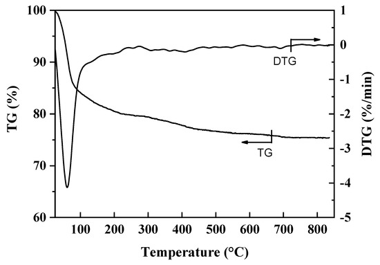
Figure 5.
Thermogravimetric (TG) and Derivative Thermogravimetric (DTG) curves of paste after 28 days of curing.
The mass loss up to around 100 °C can be attributed to the release of evaporable water. The dehydration of C–A–S–H(I) is responsible for the mass loss between 100 °C and 200 °C, whereas the mass loss between 300 °C and 400 °C is associated with the decomposition of Hydrotalcite [40].
FT-IR spectrum of the paste is reported in Figure 6.
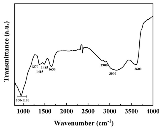
Figure 6.
FT-IR spectrum of paste after 28 days of curing.
The wide and broad region between 2900 and 3700 cm−1 can be attributed to hydrogen-bonded surface hydroxyl stretching vibrations of H2O molecules. In particular, the band centered at 3600 cm−1 is attributed less strongly hydrogen-bonded interlayer water molecules. The broad peak centered near 3000 cm−1, instead, is due to the O–H stretch of strongly polarized H-bonded water in the interlayer of the cementitious minerals. The band at 1650 cm−1 can be attributed to O–H bending mode of molecular water.
The net small peak at 2900 cm−1 is due to the hydrogen bonding of H2O and interlayer of SO42− anions in hydrotalcite. The broad band in the range of 1100–850 cm−1 can be attributed to the stretching modes of the SiQn(mAl) units. The absence of distinctive sharp bands is indicative of widely distributed bonds stretching modes in the paste. Bands at ~1485 cm−1 at ~1370 cm−1 are produced by the splitting of band at 1415 cm−1 that arises from the interaction of CO32− with OH groups in Hydrotalcite.
In Figure 7 the flexural and compressive strengths of plain mortar at 2, 7 and 28 days of curing are reported. The adopted mix design allows to obtain a fast development of the mechanical strength, with compressive strength value of 18.61 ± 0.63 MPa after two days of curing.
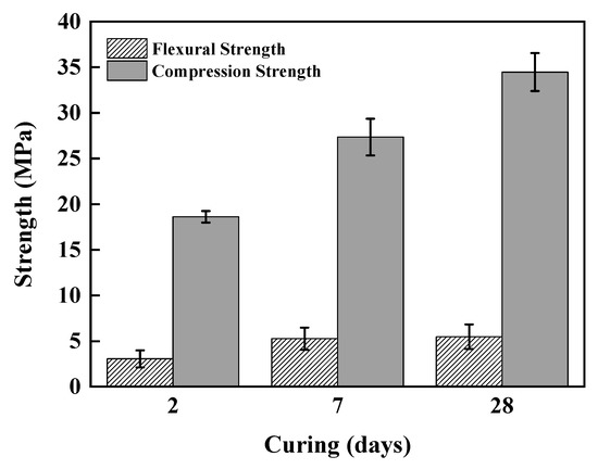
Figure 7.
Flexural and compressive strength vs. curing days.
The results for capillary absorption testing of the matrix are shown in Figure 8. Experimental data properly fit the model with a R2 = 0.99. Sorpitivity (S), which is related to the water absorption and diffusion in the mortar by capillarity, is equal to 0.27 kg/(m2 min0.5).
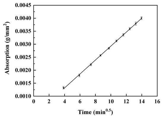
Figure 8.
Capillary absorption vs. time.
Alkali-activated materials are usually characterized by significantly higher drying shrinkage and moisture loss than traditional OPC, up to six time higher which can result in cracking and loss of durability and serviceability in restrained elements [41]. The type of reactive powders and the type and content of alkaline activators play a pivotal role in determining the extent of the shrinkage [42]. To mitigate the free shrinkage, 2 wt% of CaO on reactive powders was added as additive in mortar mix design. Its reaction to give calcium hydroxide with a volume increase of around 90% provides an expansive strain that partially compensates the shrinkage of the alkali-activated mortars. To highlight and discuss the modifications induced by CaO on the free shrinkage and mass loss behavior of the matrix, a mortar with the same composition without CaO has been used as reference (identified as S2KS7F2A1). As can be observed from Figure 9, the use of CaO lowers the overall free shrinkage from 2800 με to ≈1800 με, with a reduction of about 35%.
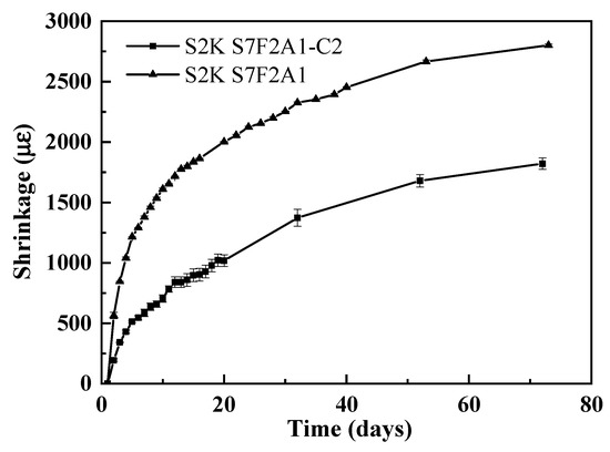
Figure 9.
Mortars’ drying shrinkage vs. curing days.
CaO is effective in compensating shrinkage at early age and determines a variation of the shrinkage without modifying the moisture loss with time, as Figure 10 clearly shows.
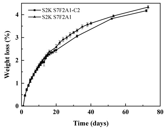
Figure 10.
Mortars’ weight loss vs. curing days.
Furthermore, it can be observed in Figure 11 that CaO causes a change in the slope of the shrinkage-mass loss curve. Reference mortar is characterized by a viscous response, with an early significant shrinkage with low moisture loss. This behavior is often observed for AAM and can ascribed to the structural incorporation of alkali cations in C–A–S–H that determines a reduction in the stacking regularity of C–A–S–H layers and is responsible of their easier tendency to collapse and redistribute upon drying [43]. The reference matrix shrinkage–mass loss curve can be described in terms of two linear steps, as reported in Figure 11.
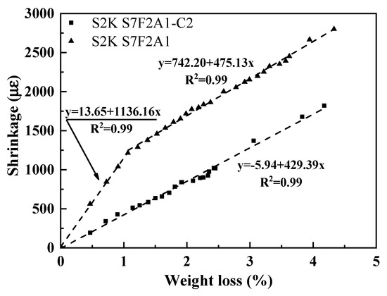
Figure 11.
Mortars’ drying shrinkage vs. weight loss.
When CaO is added, the viscous response is reduced and only one linear trend between drying shrinkage and moisture loss is observed. Analogue behavior is experienced for OPC mortars [43]. Interestingly, the second linear step of the reference mortar linear and mortar admixed with CaO show similar slopes.
In Table 3 the capillary water absorption, compressive strength and drying shrinkage of the alkali-activated mortar used in the present investigation are compared with the values of different available commercial mortars (a natural hydraulic lime and a cementitious mortar), obtained from their technical data sheets.
Table 3.
Capillary absorption and mechanical properties of the alkali-activated mortar and of a selection of commercial mortars.
As can be observed in Table 3, the measured capillary absorption value of the alkali-activated mortar falls within the range of values that occurs in commercial matrices. In particular, capillary absorption is comparable to the value reported for the Mineral-Natural Hydraulic Lime (NHL) mortar, which is the one provided by the manufacturer, to be coupled with the basalt textile used in the present investigation. The compressive strength value of the alkali-activated matrix is higher than those certified for the marketed matrices, whereas a compensation or control of the drying shrinkage is implemented for all the commercial mortars.
3.2. FRAAM Composite: Mechanical Behavior
Direct tensile and direct shear tests were carried out to investigate the load-bearing capacity, bond strength on substrate and failure modes of FRAAM composites.
In Figure 12, the tensile tests, reported in terms of stress vs. strain response curves are shown. Stress was calculated according to Equation (2). Strain was calculated by dividing the recorded displacements by measurement base of the devices.
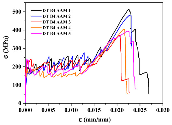
Figure 12.
Tensile test: stress vs. strain response curves.
Based on the obtained response curves, it can be concluded that the behavior of the material is similar to the generally accepted relationship, which is shown in Figure 13. Region I corresponds to the un-cracked stage in which the mortar contributes to both the stiffness and the load-bearing capacity of the composite; region II, which begins with the occurrence of the first crack in the matrix, corresponds to the crack development stage; finally, region III, which corresponds to the post-cracking stage, is followed by failure of the reinforcement [6,14].
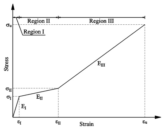
Figure 13.
Characteristic stress–strain response curve of composite specimens.
When the composites show, under direct tensile test, a tri-linear stress–strain response curve the behavior can be assessed by computing the stress and strain at the first mortar cracking, that represents the transition between region I and II and tensile modulus of elasticity in region I; the stress and strain at the transition between region II and III and tensile modulus of elasticity in region II; the ultimate stress, strain and tensile modulus of elasticity in region III, that were evaluated according to D’Antino et al. [45].
Furthermore, exploitation ratio can be obtained as follows:
where
Exploitation ratio [vs. textile] = σu/σf
- σu = composite ultimate tensile strength
- σf = textile tensile strength
All the calculated values, for each specimen tested, as well as their average and exploitation ratios, are reported in Table 4.
Table 4.
Results of tensile tests on composite specimens: the main values related to the stages.
The high εI scattering is associated with the presence, in some specimens’ response curve, of a linear branch followed by a non-linear response up to the onset of the first crack. The presence of a nonlinear response in region I was also observed by D’Antino et al. [45] and was attributed to a gradual microcracking or pre-existing microcracks of the matrix not visible to the naked eye [46], resulting in the first macro-crack. In this case, EI was evaluated as the slope of the linear branch [45]. For the examined composite, pre-existing microcracks could have formed during curing as a consequence of mortar shrinkage.
In region II the slope of the crack development stage was calculated by fitting the stress–strain curve between points (σI, εI) and (σII, εII) [45]. Stress σII and the corresponding strain εII define the point of transition between region II and region III, which corresponds to the onset of the linear branch of the stress–strain curve where the applied load is carried out only by the fibers. The fitting process provides a slope that is different from that corresponding to the line connecting points (σI, εI) and (σII, εII).
In region II, multiple cracking occurs that causes the stress–strain curves to show several drops, which indicate abrupt, brief partial unloading of the specimen due to formation of new cracks and therefore redistribution of deformations over the specimen length [6]. The higher dispersion of the results is an effect of the intrinsic variability of the observed cracking phenomena. Transverse cracks, mostly located at fiber bundles, as can be observed in Figure 14A, can be attributed to the waviness of the basalt textile (Figure 14B,C), which induces local stress concentration in those regions, where, in addition, a concurrent reduction of matrix thickness is produced by the inclusion of the textile [45]. Lengthwise cracks at the fabric-to-matrix interface stem from the initial misalignment of the yarns being removed while increasing the applied strain that leads to matrix spalling.
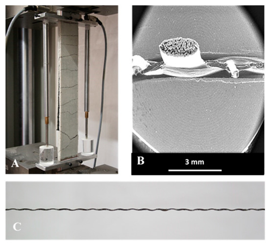
Figure 14.
(A) Tensile test: crack pattern (end of stage II); (B) yarn transversal section; (C) waviness of the warp yarn.
In region III, the load is borne by the reinforcement in the cracked area of the specimen; thus, the composite stiffness in that region should be equal to the stiffness of the reinforcement. The actual slope was found to be lower than the expected value. This finding can be attributed to two phenomena that can occur. The former is the failure of some filaments occurring simultaneously to the matrix cracking as a result of the previously described stress concentrations. The latter is that some of the filaments that are inside the core of the yarns are not bonded to the outer ones, as shown in Figure 14B. This causes a non-optimal loading transfer [47]. Composites then fail by sequential tensile failure of the fiber bundles. The misalignment that is shown in Figure 14C is acquired during weaving of the textile. The waviness causes a strain reserve in the textile. In the crack development stage (region II), with the increasing of applied displacement, textile recovers the strain reserve thus causing numerous matrix cracks and spalling. The waviness is thus also responsible for the large extent of region II. Only when the initial misalignment is recovered stress–strain response moves to region III. Furthermore, the recovering of the strain reserve initially stored in the waviness of basalt textile caused a delayed loading of the reinforcement that produced, in the FRAAM composites, a stress–strain response shifted towards larger strains [47], confirming the outcomes of the tensile characterization of textile reinforced inorganic-matrix composites made up with carbon and basalt stitch-bonded textiles reported by D’Antino et al. [45].
To highlight how the alkali-activated matrix affects the tensile behavior of the strengthening system, the major outcomes of the composites tested in the present work and those obtained by testing an available commercial system based on the same basalt textile [14] are summarized in Table 5. In particular, the commercial mortar used in [14] was the Mineral-Natural Hydraulic Lime (NHL), whose main properties are reported in Table 3.
Table 5.
Tensile tests results: FRAAM composite and commercial system [14].
In region I, the mortar significantly contributes to both the stiffness and the load-bearing capacity of the composite. The use of the mineral-NHL mortar in place of alkali-activated mortar leads to a reduction of the tensile modulus of elasticity EI. The higher εI scattering observed for the basalt FRAAM can arise from the lower dimensional stability of alkali-activated mortar than the commercial mineral-NHL mortar.
The stress σI,m was calculated by dividing the load corresponding to the first mortar cracking by the cross-sectional area of the specimens. Stress values σI,m obtained for both composites are lower than the estimated mean tensile strengths of their plain mortars. This can be attributed to the occurrence of matrix cross-sectional areas that are unsymmetrical and reduced due to the waviness of warp fibers bundles and the presence bonded joints. The ultimate stress, strain and tensile modulus of elasticity in region III and the exploitation ratio are similar in the two systems, as the load, in region III, is borne by the reinforcement in the cracked area of the specimen.
The single lap direct shear test, in a push-pull configuration, was used to study shear debonding of FRAAM to masonry substrate. The composite-to-substrate bond strength represents a fundamental information to evaluate the effectiveness of the externally bonded reinforcements. The results of the single-lap shear tests in terms of load-global slip response curves and main numerical results are reported in Figure 15 and Table 6 respectively. In particular, peak stress was calculated according to Equation (2) and the exploitation ratios were calculated as follows:
where:
Exploitation ratio [vs. textile] = σmax/σf
Exploitation ratio [vs. tensile] = σmax/σu
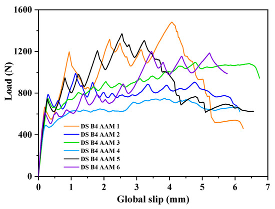
Figure 15.
Direct shear test: load-global slip response curves.
Table 6.
Results of direct shear tests.
- σmax = peak stress
- σf = textile tensile strength
- σu = average composite ultimate tensile strength
In the load-slip response curve of the basalt FRAAM, several slight load drops occur. These can be associated with an interfacial longitudinal crack along the fabric and the transversal cracks on the external matrix layer formed and developed during the test. This cracking is originated by the slippage of the fabric at the internal matrix layer interface as a consequence of the interfacial shear stress increasing. Since the external matrix layer is bonded to the reinforcement fabric, it translates with the slipped fabric. Similar behavior has been found when lime mortars are used as matrix to prepare FRCM composites, whereas when Portland cement is used only one crack often develops [48]. Average peak load around 1148 N and global slip around 6 mm were measured.
FRCM failure modes depend on the layout and nature of the textile, the use of a coating on fibers and its nature, the mechanical properties of the matrix and substrate, among many others [3]. Common failure modes involve the textile-to-matrix interface, the mortar-to-substrate interface and the slippage of the textile out of the mortar matrix [49]. In the present investigation, the debonding at the textile-to-matrix interface (C) was the most observed failure mode (Figure 16a). It was accompanied in some cases by the tensile rupture of the textile (E) (Figure 16b). The first detected failure mode is often found when textiles with insufficient or low grid spacing are used, causing a non-optimal penetration of the matrix in the voids of the textile, whereas textile rupture often occurs in weak textiles, such as basalt or glass [49]. The exploitation ratios, both vs. textile and tensile average strengths, are coherent with the observed failure modes.
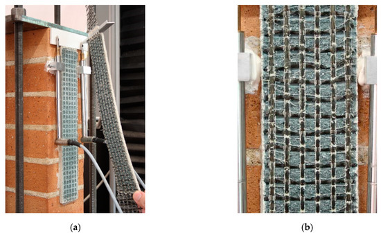
Figure 16.
(a) Failure mode (C), (b) detail of textile rupture in the failure mode (C/E).
In Table 7, the major outcomes of direct shear tests of the composites tested in the present work are compared with the ones obtained using a commercial system based on the same basalt textile [14]. In particular, the commercial mortar used in [14] was the Mineral-Natural Hydraulic Lime (NHL), whose main properties are reported in Table 3; the composite strips had the same bonded length as those tested in the present investigation and they were externally bonded on brickwork substrate with the same properties as in the current paper.
Table 7.
Direct shear tests results: FRAAM composite and commercial system [14].
Debonding at the textile-to-matrix interface (C) was the only observed failure mode for Basalt FRCM strips produced using the commercial matrix. It is worthy to be noted that Basalt-FRAAM composites, even in presence of some strips that fail also by a tensile rupture of the textile, show a lower average peak stress value than commercial Basalt-FRCM composites. This can be associated with different matrix–fiber bonds and to the different shrinkage behaviors of the matrix [50].
4. Conclusions
The results of the experimental campaign carried out on basalt FRAAM can be summarized as follows:
- An inorganic matrix based on an alkali-activated ternary blend of industrial by products was designed based on the one-pot philosophy. The main crystalline reaction product was an aluminum-modified calcium silicate hydrate gel (C–A–S–H) characterized by a wide distribution of the SiQn(mAl) units. The addition of an expansive agent (CaO) reduced the free shrinkage of about 35%, to ≈1800 με, whereas higher dimensional stability is reported for commercial mortars. Capillary absorption of around ≈0.27 kg/(m2∙min0.5) was measured, which is close to values reported for commercial mortars.
- The tensile test of basalt FRAAM systems displayed three characteristic response stages (I) un-cracked, (II) crack development and (III) cracked. The response curves highlight that the behavior of the composite mainly relies on crack development and widening. The average ultimate stress (434 MPa) and the tensile modulus of elasticity in region III (39 GPa) were lower than those of the dry textile, with an average exploitation ratio of 0.46. The composites failed by sequential tensile failure of the fiber bundles. The waviness of the warp yarns caused the large extent of region II. Matrix microcracks not visible to the naked-eye can form, in some specimens, during the curing as a consequence of mortar shrinkage. They cause in the region I of the response curve a linear branch followed by a non-linear response up to the onset of the first crack. Matrix pre-existing microcracks are responsible of the increase of the εI scattering with respect to the commercial system used as reference.
- Shear bond tests, performed on masonry substrates, displayed response curves characterized by the formation and development of an interfacial longitudinal crack and transversal cracks with corresponding load drops. Average peak load around 1148 N and an average exploitation ratio (vs. textile) of 0.4 were measured. The observed failure modes were the debonding at the textile-to-matrix interface in some cases associated with the tensile rupture of the textile. The commercial system used as reference showed a slightly higher average peak stress value than the FRAAM composite, which can be ascribed to the different shrinkage behavior of the two mortars.
Further investigation should be focused on increasing the dimensional stability of alkali-activated matrix that would improve the performance of the tested FRAAM composite.
Author Contributions
Conceptualization, S.C. and F.C.; methodology, S.C. and A.I.; software, S.C. and A.I.; validation, S.C. and F.C.; formal analysis, S.C.; investigation, S.C., A.I. and F.C..; resources, F.C. and S.C.; data curation, S.C. and A.I.; writing—original draft preparation, S.C. and F.C.; writing—review and editing, S.C. and F.C.; visualization, S.C. and A.I.; supervision, F.C. and S.C. All authors have read and agreed to the published version of the manuscript.
Funding
This research received no external funding.
Conflicts of Interest
The authors declare no conflict of interest.
References
- Garbin, E.; Valluzzi, M.R.; Panizza, M. Experimental Assessment of Bond Behaviour of Fibre-Reinforced Polymers on Brick Masonry. Struct. Eng. Int. 2010, 20, 392–399. [Google Scholar] [CrossRef]
- Foraboschi, P. Strengthening of Masonry Arches with Fiber-Reinforced Polymer Strips. J. Compos. Constr. 2004, 8, 191–202. [Google Scholar] [CrossRef]
- Donnini, J.; Corinaldesi, V.; Nanni, A. Mechanical properties of FRCM using carbon fabrics with different coating treatments. Compos. Part B Eng. 2016, 88, 220–228. [Google Scholar] [CrossRef]
- Papanicolaou, C.G.; Triantafillou, T.; Karlos, K.; Papathanasiou, M. Textile-reinforced mortar (TRM) versus FRP as strengthening material of URM walls: In-plane cyclic loading. Mater. Struct. 2006, 40, 1081–1097. [Google Scholar] [CrossRef]
- Valluzzi, M.R.; Modena, C.; De Felice, G. Current practice and open issues in strengthening historical buildings with composites. Mater. Struct. 2014, 47, 1971–1985. [Google Scholar] [CrossRef]
- Caggegi, C.; Lanoye, E.; Djama, K.; Bassil, A.; Gabor, A. Tensile behaviour of a basalt TRM strengthening system: Influence of mortar and reinforcing textile ratios. Compos. Part B Eng. 2017, 130, 90–102. [Google Scholar] [CrossRef]
- D’Ambrisi, A.; Focacci, F.; Caporale, A. Strengthening of masonry–unreinforced concrete railway bridges with PBO-FRCM materials. Compos. Struct. 2013, 102, 193–204. [Google Scholar] [CrossRef]
- D’Antino, T.; Carloni, C.; Sneed, L.; Pellegrino, C. Matrix–fiber bond behavior in PBO FRCM composites: A fracture mechanics approach. Eng. Fract. Mech. 2014, 117, 94–111. [Google Scholar] [CrossRef]
- Balsamo, A.; Di Ludovico, M.; Prota, A.; Manfredi, G. Masonry walls strengthened with innovative composites. Spec. Publ. 2011, 275, 1–18. [Google Scholar] [CrossRef]
- De Santis, S.; De Felice, G. Steel reinforced grout systems for the strengthening of masonry structures. Compos. Struct. 2015, 134, 533–548. [Google Scholar] [CrossRef]
- Leone, M.; Aiello, M.A.; Balsamo, A.; Carozzi, F.G.; Ceroni, F.; Corradi, M.; Gams, M.; Garbin, E.; Gattesco, N.; Krajewski, P.; et al. Glass fabric reinforced cementitious matrix: Tensile properties and bond performance on masonry substrate. Compos. Part B Eng. 2017, 127, 196–214. [Google Scholar] [CrossRef]
- Carozzi, F.G.; Bellini, A.; D’Antino, T.; De Felice, G.; Focacci, F.; Hojdys, Ł.; Laghi, L.; Lanoye, E.; Micelli, F.; Panizza, M.; et al. Experimental investigation of tensile and bond properties of Carbon-FRCM composites for strengthening masonry elements. Compos. Part B Eng. 2017, 128, 100–119. [Google Scholar] [CrossRef]
- Lignola, G.P.; Caggegi, C.; Ceroni, F.; De Santis, S.; Krajewski, P.; Lourenço, P.; Morganti, M.; Papanicolaou, C. (Corina); Pellegrino, C.; Prota, A.; et al. Performance assessment of basalt FRCM for retrofit applications on masonry. Compos. Part B Eng. 2017, 128, 1–18. [Google Scholar] [CrossRef]
- Iorfida, A.; Verre, S.; Candamano, S.; Ombres, L. Tensile and Direct Shear Responses of Basalt-Fibre Reinforced Mortar Based Materials. In Strain-Hardening Cement-Based Composites. SHCC 2017; RILEM Bookseries; Mechtcherine, V., Slowik, V., Kabele, P., Eds.; Springer: Dordrecht, The Netherlands, 2018; Volume 15, pp. 544–552. [Google Scholar] [CrossRef]
- Purdon, A.O. The action of alkalis on blast-furnace slag. J. Soc. Chem. Ind. 1940, 59, 191–202. [Google Scholar]
- Pacheco-Torgal, F. Introduction to Handbook of Alkali-activated Cements, Mortars and Concretes; Woodhead Publishing: Cambridge, UK, 2015; pp. 1–16. [Google Scholar] [CrossRef]
- Provis, J. Alkali-activated materials. Cem. Concr. Res. 2018, 114, 40–48. [Google Scholar] [CrossRef]
- Coppola, L.; Coffetti, D.; Crotti, E.; Marini, A.; Passoni, C.; Pastore, T. Lightweight cement-free alkali-activated slag plaster for the structural retrofit and energy upgrading of poor quality masonry walls. Cem. Concr. Compos. 2019, 104, 103341. [Google Scholar] [CrossRef]
- Coppola, L.; Bellezze, T.; Belli, A.; Bignozzi, M.; Bolzoni, F.M.; Brenna, A.; Cabrini, M.; Candamano, S.; Cappai, M.; Caputo, D.; et al. Binders alternative to Portland cement and waste management for sustainable construction—Part 1. J. Appl. Biomater. Funct. Mater. 2018, 16, 186–202. [Google Scholar] [CrossRef]
- Coppola, L.; Bellezze, T.; Belli, A.; Bignozzi, M.C.; Bolzoni, F.M.; Brenna, A.; Cabrini, M.; Candamano, S.; Cappai, M.; Caputo, D.; et al. Binders alternative to Portland cement and waste management for sustainable construction—Part 2. J. Appl. Biomater. Funct. Mater. 2018, 16, 207–221. [Google Scholar] [CrossRef]
- Candamano, S.; Sgambitterra, E.; Lamuta, C.; Pagnotta, L.; Chakraborty, S.; Crea, F. Graphene nanoplatelets in geopolymeric systems: A new dimension of nanocomposites. Mater. Lett. 2019, 236, 550–553. [Google Scholar] [CrossRef]
- Sgambitterra, E.; Lamuta, C.; Candamano, S.; Pagnotta, L. Brazilian disk test and digital image correlation: A methodology for the mechanical characterization of brittle materials. Mater. Struct. 2018, 51, 19. [Google Scholar] [CrossRef]
- Candamano, S.; De Luca, P.; Frontera, P.; Crea, F. Production of Geopolymeric Mortars Containing Forest Biomass Ash as Partial Replacement of Metakaolin. Environments 2017, 4, 74. [Google Scholar] [CrossRef]
- Burciaga-Díaz, O.; Magallanes-Rivera, R.X.; Escalante-García, J.I. Alkali-activated slag-metakaolin pastes: Strength, structural, and microstructural characterization. J. Sustain. Cem. Mater. 2013, 2, 111–127. [Google Scholar] [CrossRef]
- Bernal, S.A.; Provis, J.; Rose, V.; De Gutiérrez, R.M. Evolution of binder structure in sodium silicate-activated slag-metakaolin blends. Cem. Concr. Compos. 2011, 33, 46–54. [Google Scholar] [CrossRef]
- Carabba, L.; Santandrea, M.; Carloni, C.; Manzi, S.; Bignozzi, M. Steel fiber reinforced geopolymer matrix (S-FRGM) composites applied to reinforced concrete structures for strengthening applications: A preliminary study. Compos. Part B Eng. 2017, 128, 83–90. [Google Scholar] [CrossRef]
- Bakharev, T.; Sanjayan, J.; Cheng, Y.-B. Sulfate attack on alkali-activated slag concrete. Cem. Concr. Res. 2002, 32, 211–216. [Google Scholar] [CrossRef]
- Bakharev, T. Durability of geopolymer materials in sodium and magnesium sulfate solutions. Cem. Concr. Res. 2005, 35, 1233–1246. [Google Scholar] [CrossRef]
- Ye, H.; Chen, Z.; Huang, L. Mechanism of sulfate attack on alkali-activated slag: The role of activator composition. Cem. Concr. Res. 2019, 125, 105868. [Google Scholar] [CrossRef]
- De Luca, P.; De Luca, P.; Candamano, S.; Macario, A.; Crea, F.; Nagy, J.B. Preparation and Characterization of Plasters with Photodegradative Action. Buildings 2018, 8, 122. [Google Scholar] [CrossRef]
- Gong, K.; White, C.E. Nanoscale Chemical Degradation Mechanisms of Sulfate Attack in Alkali-activated Slag. J. Phys. Chem. C 2018, 122, 5992–6004. [Google Scholar] [CrossRef]
- Bhutta, M.A.R.; Hussin, W.M.; Azreen, M.; Tahir, M.M. Sulphate Resistance of Geopolymer Concrete Prepared from Blended Waste Fuel Ash. J. Mater. Civ. Eng. 2014, 26, 04014080. [Google Scholar] [CrossRef]
- Ismail, I.; Bernal, S.A.; Provis, J.; Hamdan, S.; Van Deventer, J.S.J. Microstructural changes in alkali activated fly ash/slag geopolymers with sulfate exposure. Mater. Struct. 2012, 46, 361–373. [Google Scholar] [CrossRef]
- Luukkonen, T.; Abdollahnejad, Z.; Yliniemi, J.; Kinnunen, P.; Illikainen, M. One-part alkali-activated materials: A review. Cem. Concr. Res. 2018, 103, 21–34. [Google Scholar] [CrossRef]
- Coppola, L.; Coffetti, D.; Crotti, E.; Candamano, S.; Crea, F.; Gazzaniga, G.; Pastore, T. The combined use of admixtures for shrinkage reduction in one-part alkali activated slag-based mortars and pastes. Constr. Build. Mater. 2020, 248, 118682. [Google Scholar] [CrossRef]
- García, J.I.E.; Fuentes, A.F.; Gorokhovsky, A.; Fraire-Luna, P.E.; Mendoza-Suarez, G. Hydration Products and Reactivity of Blast-Furnace Slag Activated by Various Alkalis. J. Am. Ceram. Soc. 2003, 86, 2148–2153. [Google Scholar] [CrossRef]
- Zhang, Y.; Zhao, Y.L.; Li, H.H.; Xu, D.L. Structure characterization of hydration products generated by alkaline activation of granulated blast furnace slag. J. Mater. Sci. 2008, 43, 7141–7147. [Google Scholar] [CrossRef]
- Ben Haha, M.; Lothenbach, B.; Le Saout, G.; Winnefeld, F. Influence of slag chemistry on the hydration of alkali-activated blast-furnace slag—Part I: Effect of MgO. Cem. Concr. Res. 2011, 41, 955–963. [Google Scholar] [CrossRef]
- Ben Haha, M.; Lothenbach, B.; Le Saout, G.; Winnefeld, F. Influence of slag chemistry on the hydration of alkali-activated blast-furnace slag—Part II: Effect of Al2O3. Cem. Concr. Res. 2012, 42, 74–83. [Google Scholar] [CrossRef]
- Bellotto, M.; Rebours, B.; Clause, O.; Lynch, J.; Bazin, D.; Elkaïm, E. Hydrotalcite Decomposition Mechanism: A Clue to the Structure and Reactivity of Spinel-like Mixed Oxides. J. Phys. Chem. 1996, 100, 8535–8542. [Google Scholar] [CrossRef]
- Cartwright, C.; Rajabipour, F.; Radlińska, A. Shrinkage Characteristics of Alkali-Activated Slag Cements. J. Mater. Civ. Eng. 2015, 27, B4014007. [Google Scholar] [CrossRef]
- Chen, J.J.; Sorelli, L.; Vandamme, M.; Chanvillard, G.; Ulm, F.-J. A Coupled Nanoindentation/SEM-EDS Study on Low Water/Cement Ratio Portland Cement Paste: Evidence for C-S-H/Ca(OH)2Nanocomposites. J. Am. Ceram. Soc. 2010, 93, 1484–1493. [Google Scholar] [CrossRef]
- Ye, H.; Radlińska, A. Shrinkage mechanisms of alkali-activated slag. Cem. Concr. Res. 2016, 88, 126–135. [Google Scholar] [CrossRef]
- Fib fib Model Code for Concrete Structures 2010. In Fib Model Code for Concrete Structures 2010; Ernst & Sohn: Berlin, Germany, 2013.
- D’Antino, T.; Papanicolaou, C. Mechanical characterization of textile reinforced inorganic-matrix composites. Compos. Part B Eng. 2017, 127, 78–91. [Google Scholar] [CrossRef]
- Arboleda, D.; Carozzi, F.G.; Nanni, A.; Poggi, C. Testing Procedures for the Uniaxial Tensile Characterization of Fabric-Reinforced Cementitious Matrix Composites. J. Compos. Constr. 2016, 20, 04015063. [Google Scholar] [CrossRef]
- Hartig, J.; Jesse, F.; Häußler-Combe, U. Influence of different mechanisms on the constitutive behaviour of textile reinforced concrete. In Proceedings of the 4th Colloquium on Textile Reinforced Structures (CTRS4), Technische Universitat Dresden, Dresden, Germany, 3–5 June 2009; pp. S157–S168. [Google Scholar]
- Tekieli, M.; De Santis, S.; De Felice, G.; Kwiecień, A.; Roscini, F. Application of Digital Image Correlation to composite reinforcements testing. Compos. Struct. 2017, 160, 670–688. [Google Scholar] [CrossRef]
- De Santis, S.; Carozzi, F.; De Felice, G.; Poggi, C. Test methods for Textile Reinforced Mortar systems. Compos. Part B: Eng. 2017, 127, 121–132. [Google Scholar] [CrossRef]
- D’Antino, T.; Sneed, L.H.; Carloni, C.; Pellegrino, C. Influence of the substrate characteristics on the bond behavior of PBO FRCM-concrete joints. Constr. Build. Mater. 2015, 101, 838–850. [Google Scholar] [CrossRef]
© 2020 by the authors. Licensee MDPI, Basel, Switzerland. This article is an open access article distributed under the terms and conditions of the Creative Commons Attribution (CC BY) license (http://creativecommons.org/licenses/by/4.0/).