Article

Method to Control the Deformation of Anti-Slide Piles in Zhenzilin Landslide

1
School of Civil Engineering, Architecture of Henan University, Kaifeng 475004, Henan, China
2
College of Science, Engineering of Flinders University, 5042 Adelaide, Australia
*
Authors to whom correspondence should be addressed.
Appl. Sci. 2020, 10(8), 2831; https://doi.org/10.3390/app10082831
Submission received: 7 March 2020 / Revised: 9 April 2020 / Accepted: 14 April 2020 / Published: 19 April 2020
(This article belongs to the Special Issue Advances in Geotechnical Engineering)

Abstract

:
Anti-slide piles were used in the region of the Zhenzilin landslide in Sichuan, China. The horizontal displacement of these piles exceeds specifications. Deterioration in bedrock properties may cause deformation, thereby causing landslide destabilization. An approach was developed for the analysis of anti-slide pile in two bedrocks with different strengths below the slip surface. A relationship has been established between the modulus of subgrade reaction of the first weak bedrock and reasonable embedded length for landfill slopes with strata of various strengths. Furthermore, the influence of embedding length on deformation has been studied to determine the reasonable embedded length, which helps reduce deformation and ensure landslide stability. The results reveal that (1) at a constant embedded length, horizontal displacement increases with the thickness of the first soft bedrock, meanwhile the maximum shear force remains constant, and the bending moment first increases followed by subsequent decrease; (2) with an increase in the embedded length, horizontal displacement and the maximum shear force of the pile in the embedded bedrock decrease, whereas the bending moment increases; (3) the maximum internal forces and horizontal displacement increase with a decrease in the subgrade reaction modulus of the first weak rock; and (4) the reasonable embedded length of an anti-slide pile increases with a decrease in the subgrade reaction modulus of the first weak bedrock. The proposed approach can be employed to design anti-slide piles in similar landslide regions to control pile-head deformation.

1. Introduction

During the construction of the Sichuan–Tibet highway, many roadbed slopes were constructed via excavation and dumping. Several backfill slopes slide along the original surface of the Sichuan–Tibet Highway in the southwest Sichuan province of China. This area is mainly characterized by Silurian strata, comprising medium-thick-layered limestone intercalated with mudstone [1]. Anti-slide piles are used in this bedrock to maintain landslide stability [2]. The pile heads often undergo lateral displacement [3,4]. If the pile head deformation is too large, cracks form in the landslide body behind the pile, which provide a channel for surface water infiltration and increase the risk of landslides [5,6].
Many recent studies have investigated the mechanism of pile deformation. In foundation engineering, the deformation behavior of piles is related to the section shape and slenderness ratio of piles [6]. In landslide prevention and control projects, anti-slide piles play an important role and coordinate deformation with the surrounding soil to improve stability of the entire slope [7,8,9,10,11]. The deformation of the pile head in a slope is related to the slope angle [12,13]. The excavation and increasing driving force of landslides behind piles will lead to pile deformation and even pile damage [14,15,16]. The deflection of the pile head is affected by the lateral load pattern, and the rectangular lateral load pattern has a greater influence on the deflection of the pile head than the trapezoidal load pattern [17,18]. When the driving force of the landslide, stratum properties, and relative stiffness of the pile are determined, the embedded depth of the anti-slide pile will directly affect the internal force and displacement of the piles [19,20].
The effective embedded length of anti-slide piles used for reinforcing slopes is analyzed via numerical simulations, theoretical calculations and experimental modeling. Poulos [21] presented an approach for the design of piles to reinforce slopes. Guo and Qin [22] and Qin and Guo [23] conducted experimental investigation into the response of vertically loaded free head single piles subjected to lateral soil movement. Cai and Ugai [24] adopted an analytical method for calculating the response of flexible piles under the laterally linear movement of the sliding layer in landslides. Wei and Cheng [25] adopted strength reduction to study the reinforcement of a row of piles on a slope. Wei et al. [26] studied the way in which expansive power and embedded pile length affected the deformation of the pile in an expansive soil region. Yang et al. [27] studied the effect of the embedded pile length on the factors of safety and pile behavior. Liu and Liu [28] and Li et al. [29] investigated the effects of pile spacing and pile-head conditions on the critical pile length. As observed, the critical pile length increases with decreasing pile spacing. Bakri et al. [30] studied the minimum socketed length in the upper-middle region of the slope, the factor of safety remaining constant. Li et al. [31] and Zhou et al. [32] studied the mechanism of pile deformation in multilayered bedrock.
The above researchers have studied the mechanism of pile deformation with a single rock layer and investigated the influence of pile length on slope stability with a multilayered stratum. However, in backfill landslides with multilayer bedrock, studies on large horizontal displacements of piles after the implementation of anti-slide piles are limited. Such excessive displacements will affect the stability of the landslide. Hence, the interaction mechanism between the deformation behavior of anti-slide piles in multilayered bedrock, and the corresponding approaches to alleviate this deformation are crucial. Using the case of the Zhenzilin landslide in Luding county located at southwest of the Sichuan province in China, the objective of this study is to investigate possible factors influencing the pile deformation. Additionally, the study proposes a method for ascertaining the reasonable buried length of anti-slide piles to control pile-head deformation in backfill landslides. The factors affecting the reasonable embedded length of anti-slide piles, pile deformation, and internal forces have been accounted for via detailed analysis.

2. Engineering Background, Site Investigation, and Laboratory Test

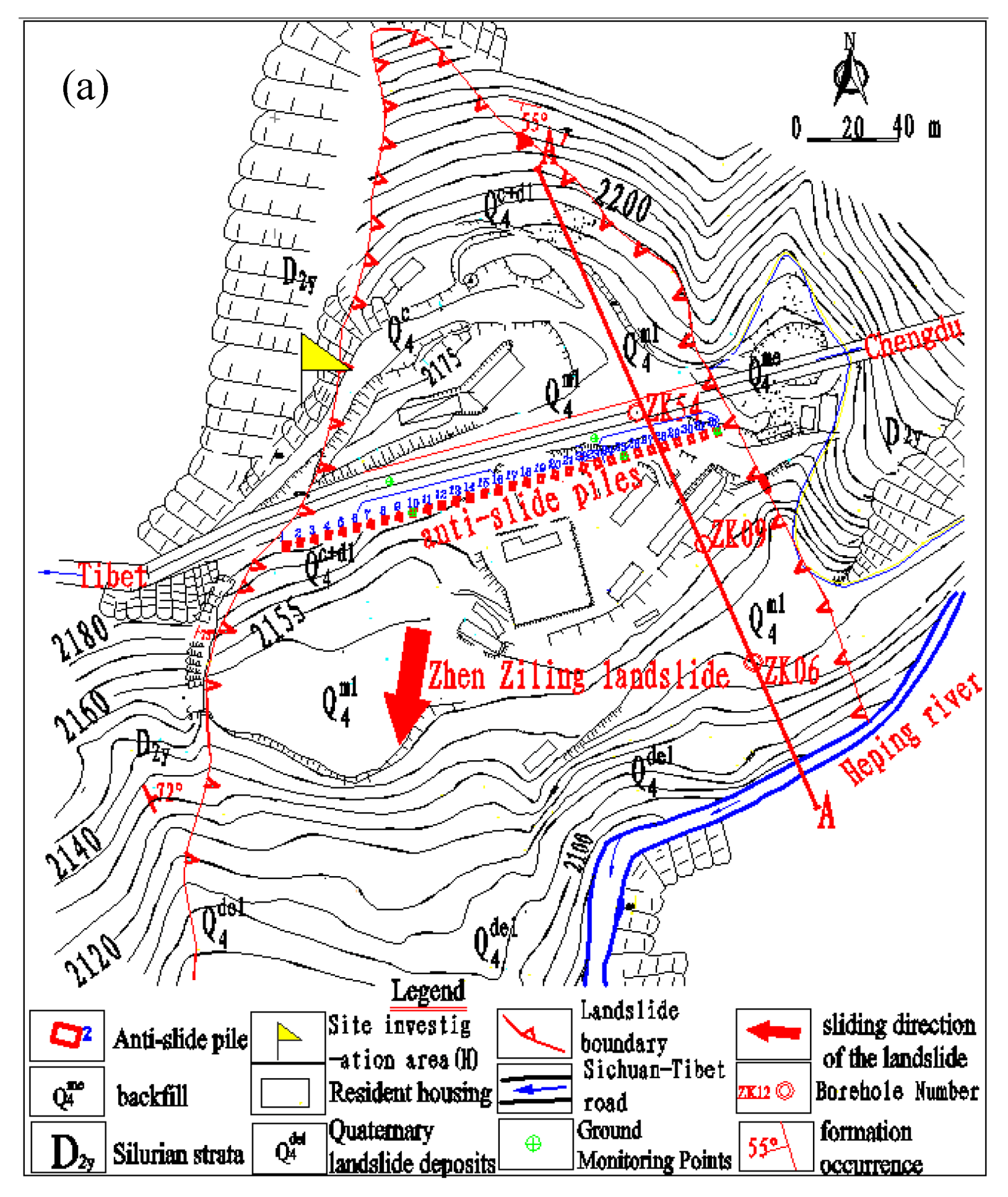
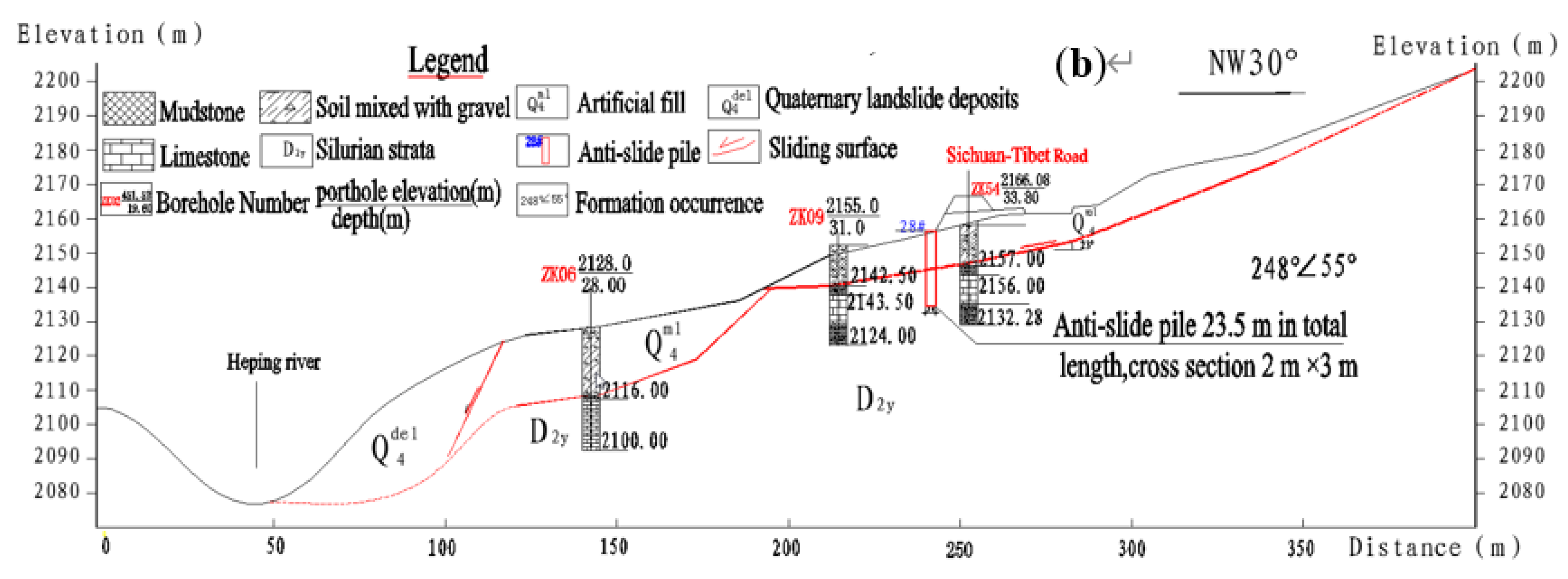
2.1. Geological Background of the Zhenzilin landslide

The Zhenzilin landslide occurred on July 23, 1998, in Luding county located at southwest of the Sichuan province of China. The incident occurred 800 m away from the west exit of the Erlangshan tunnel—a project concerning the construction of the Sichuan–Tibet highway [1]. The coordinates of the landslide location are 29.841397° N latitude and 102.264781° E longitude. It is about 172 km away from Chengdu. The Sichuan–Tibet Highway (G318 Road) passes in front of the landslide. There were about 50 officers and soldiers living in the landslide area. The toll station of Erlangshan Highway is threatened by the landslide (see Figure 1). The front edge of the landslide is eroded by water from the Heping river.
The Zhenzilin landslide is approximately 390 m long and 210 m wide, and the average thickness of the sliding body is 25 m. The landslide area is approximately 9.87 km2 and its volume is 2.1 million m3 (see Figure 2a). The main sliding direction of the sliding body is 187°. The Zhenzilin landslide is a landfill slope [2]. The landslide material mainly comprises artificial fill from the Erlangshan Tunnel construction. Silurian strata are the main characteristics of this area with the interbedding of limestone and mudstone. The tendency of limestone and mudstone is 40° and the dip angle is 55°.

2.2. Landslide Stabilizing Measures

Twenty anchors and twelve ordinary anti-slide piles were used to prevent and control the Zhenzilin landslide [2]. The piles were installed along the Sichuan–Tibet highway at an elevation of approximately 2100 m (refer to Figure 2b). The ordinary anti-slide piles were 23.5 m long (see Figure 2b); 2 m wide (b); and 3 m high (a). The anti-slide piles were installed 6 m apart. There existed four ordinary anti-slide piles for which the embedded section length (h) equaled 8.5 m in the AA’ cross-section of the Zhenzilin landslide (see Figure 2b), and the pile length above the slip surface (h1) equaled 15 m. Anti-slide piles were installed at points where the bedrock comprised three rock types—the 1-m-deep upper mudstone (weak) layer, the limestone (hard) layer measuring approximately 7.5 m deep, and sliding mass containing backfill. The strength of the soil was observed in terms of the internal friction angle. The cohesion between soil particles was very small. To simplify calculations, the distribution form of the driving force behind a pile was taken as triangular [33]. The bases of some piles were located in the weak rock layer owing to the interbedding relationship between limestone and mudstone. Hence, free conditions were considered for such pile ends.

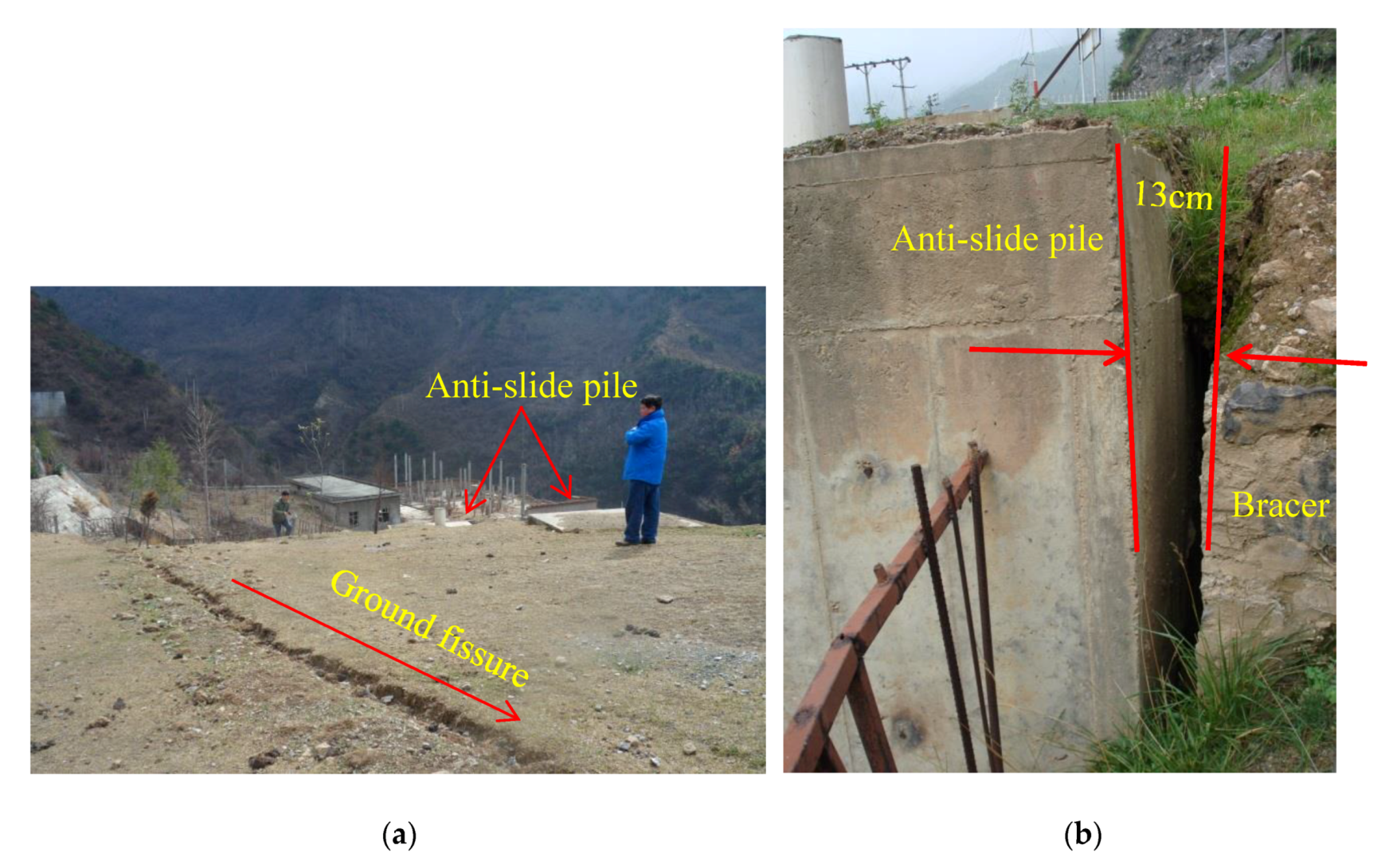
2.3. Site Investigation of Anti-Slide Pile Deformations

Electronic Total Station displacement monitoring and site investigation were conducted to further study the deformation behavior of anti-slide piles. Several obvious cracks were discovered at the back edges of anti-slide piles during our site investigation of the Zhenzilin landslide. The widest crack was approximately 13 cm (see Figure 3), which is consistent with the monitoring results of the pile head by the Electronic Total Station. The cracks in the landslide body would provide channels for surface water seeping into the ground [5], which would weaken the strength of mudstone below the slip surface and increase the landslide risk. Consequently, the causes of the deformation of the anti-slide pile require further study to guide the design of anti-slide piles in similar bedrock areas.
Following the landslide treatment, the highway toll station and four-story dormitories were built on the landslide. According to the load design code, an extra 50-kN/m load was imposed on the anti-slide piles.

2.4. Laboratory Test of Sandstone and Mudstone

A site investigation area (H) located at the rear edge of the Zhenzilin landslide with a steep cliff in the Silurian strata was studied. To further study the physical and mechanical properties of bedrock, some rock samples were obtained and tested in the laboratory (see Figure 4). The experimental results pertaining to geotechnical parameters are listed in Table 1. Rocks at the investigation site in this study show similar characteristics to those of the Zhenzilin landslide bedrock.
Laboratory compressive strength tests were conducted to determine the modulus of subgrade reaction of the bedrock. The compressive strength test device system was developed based on the rock test code of highway engineering [34,35]. The results of the laboratory compressive test show that the compressive strengths of the moderately weathered mudstone and weathered limestone were 12.4 MPa and 38.59 MPa, respectively. The corresponding modulus of subgrade reaction were 1 × 10⁵ kN/m3 and 3.4 × 10⁵ kN/m3, according to a study on the design of an anti-slide pile [36].

3. Methodology and Validation

3.1. Methods for Anti-Slide Pile Calculations in Two Bedrocks with Different Strengths below the Slip Surface

The anti-slide pile can be divided into an elastic pile and a rigid pile. When β× h is < 1.0 it belongs to a rigid pile; otherwise, it belongs to an elastic pile [36]. The h is the embedded section length of the pile. The pile deformation coefficient (β) is calculated using the following formula [34]:
β = ( k B p 4 E I ) 1 4
where k denotes the modulus of subgrade reaction of the bedrock for the anti-slide pile under the action of lateral forces determined by the compressive strength of the rock [36]; E denotes Young’s modulus of the pile, I denotes moment of inertia of the pile, and Bp denotes calculation width of the pile (Bp = b + 1, in meter, for rectangular section, b is the width of the pile section). If taking k = 100,000 kPa/m, E = 30,000,000 kPa, Bp = 3 m, I = 4.5 m4, and h = 7m; β = 0.154 m−1 and β × h = 1.08. Thus, as regards engineering applications, the behavior of most of the anti-slide piles are elastic in accordance with Equation (1). For bedrocks containing two layers of rocks with different properties (see Figure 5a), the lateral load acting on the pile below the sliding surface can be expressed using two equations as following [36]:
{ E I d 4 x d y 4 + x k 1 B P = 0 ( 0 y y 1 ) E I d 4 x d y 4 + x k 2 B P = 0 ( y 1 < y h )
where x is the deflection of the pile, y is the depth measured from the slip surface, k1 is the modulus of the subgrade reaction of the first layer of rock below the slip surface, and y1 is the thickness of the first rock; k2 is the modulus of subgrade reaction of the second layer of rock below the slip surface; h is the embedded section length of the anti-slide piles. The other parameters are the same as above.
By solving the two equations described in Equation (2), the following expressions can be obtained [31]:
{ M yi = 4 x i 1 β i 2 E I φ 3 i 4 θ i 1 β i E I φ 4 i + M i 1 φ 1 i + Q i 1 β i φ 2 i Q yi = 4 x i 1 β i 3 E I φ 2 i 4 θ i 1 β i 2 E I φ 3 i 4 M i 1 β i φ 4 i + Q i 1 φ 1 i θ y i = β i ( 4 x i 1 φ 4 i + θ i 1 β i φ 1 i + M i 1 β i 2 E I φ 2 i + Q i 1 β i 3 E I φ 3 i ) x y i = x i 1 φ 1 i + θ i 1 β i φ 2 i + M i 1 β i 2 E I φ 3 i + Q i 1 β i 3 E I φ 4 i ( i = 1 , 2 )
where Qyi, Myi, θyi, and xyi denote the shear force, bending moment, rotation angle, and horizontal displacement for the pile below the sliding surface of the two bedrock layers with different strengths that change with depth, respectively; i = 1 represents the first layer of rock below the slip surface; i = 2 represents the second layer of rock below the slip surface; Q1, M1, θ1, and x1 denote the shear force, bending moment, rotation angle, and the horizontal displacement of the pile located at the bottom of the first bedrock layer, respectively; Q0, M0, θ0, and x0 denote the shear force, bending moment, rotation angle, and the horizontal displacement for the pile located at the slip surface, respectively; and φ1i, φ2i, φ3i, and φ4i denote influence moduli that can be calculated using the following equations [31]:
{ φ 1 i = cos ( β i Δ y ) cosh ( β i Δ y ) φ 2 i = 1 2 [ sin ( β i Δ y ) cosh ( β i Δ y ) + cos ( β i Δ y ) sinh ( β i Δ y ) ] φ 3 i = sin ( β i Δ y ) sinh ( β i Δ y ) φ 4 i = 1 4 [ sin ( β i Δ y ) cosh ( β i Δ y ) cos ( β i Δ y ) sinh ( β i Δ y ) ] Δ y = y i y i 1 ( i = 1 , 2 )
In the above equations, Δy denotes the thickness of the rock layer with different strengths below the sliding surface; yi denotes the distance from the origin below the sliding surface; and βi denotes the modulus of deformation. This can be obtained from the following formula [36] (the other parameters are the same as above):
β i = k i × B p 4 E I 4 ( i = 1 ,   2 )
Other external forces acting on the pile tip are not considered in the calculation. The solution of Equation (3) is dependent on the values of M0, Q0, x0, and θ0. M0 and Q0 can be solved using lateral load conditions. x0 and θ0 can be solved using the pile-bottom boundary condition. There exist three types of bottom boundary conditions—free, articulated, and fixed. In this study, the free boundary condition was considered for performing calculations in accordance with prevailing engineering conditions [34]. By substituting calculated values of M0, Q0, x0, and θ0 into Equation (3), the bending moment (Myi), shear force (Qyi), horizontal displacement (xyi), and rotation angle (θyi) can be obtained for the load acting on the pile at any depth below the slip surface.

3.2. Calculation Method for an Anti-Slide Pile above the Slip Surface

To ensure engineering safety, the section of an anti-slide pile above the slip surface is generally considered as a cantilever beam. If the thrust distribution of the landslide behind the pile is triangular, according to structural mechanics, the shear force (Qy) and bending moment (My) for the pile above the sliding surface can be expressed as follows:
{ Q y = q 1 ( h 1 | y | ) 2 2 h 1 ( y < 0 , | y | h 1 ) M y = q 1 ( h 1 | y | ) 3 6 h 1 ( y < 0 , | y | h 1 )
where y is the distance from the origin (see Figure 5a); h1 is the length of the anti-slide pile above the slip surface; and q1 is the intensity of the distributed driving force acting on the pile at the sliding surface (refer to Figure 5a).
The horizontal displacement (Γy) is related to the pile deformation (ΔE), rotation (ΔR), and displacement (x0) caused by the triangular distributed driving force (see Figure 5b); hence, the displacement of the pile is established as follows:
Γ y = x 0 + Δ R ( y ) + Δ E ( y ) ( y < 0 , | y | h 1 )
The rotation(ΔR) can be expressed as follows:
Δ R ( y ) = θ 0 × | y | ( y < 0 , | y | h 1 )
Here, x0 and θ0 denote the horizontal displacement and rotation angle of the pile at the slip surface, respectively. As stated above, the displacement (ΔE) of a pile that was induced by triangular thrust load of the landslide can be calculated as follows:
Δ E ( y ) = q 1 120 E I h 1 [ 4 h 1 5 5 h 1 4 ( h 1 | y | ) + ( h 1 | y | ) 5 ] ( y < 0 , | y | h 1 )
Then, Equations (8) and (9) are introduced into Equation (7). The complete expression of the horizontal displacement of an anti-slide pile above the slip surface can be obtained as follows:
Γ y = x 0 + θ 0 × | y | + q 1 120 E I h 1 [ 4 h 1 5 5 h 1 4 ( h 1 | y | ) + ( h 1 | y | ) 5 ] ( y < 0 , | y | h 1 )

3.3. Validation of the Calculation Method for the Zhenzilin landslide

The anti-slide pile (A-type) with a cross-section from A to A′ of the Zhenzilin landslide was selected in the calculation. The spacing between the piles is 6m. The moment of inertia of the anti-slide pile (I) is equal to b × a3/12 = 4.5 m4. The Young’s modulus (E) of the anti-slide pile is 30 GPa. The driving force of the landslide (p) was 1500 kN/m. Each pile bears driving force of the landslid in the range of 6m [2]. The additional load that acted on the anti-slide pile because of highway toll stations is 50 kN/m. At present, the total load is 1550 kN/m. The upper layer of mudstone is 1 m (Δy1 = 1m). The lower limestone layer is approximately 7.5 m (Δy2 = 7.5m). Therefore, the buried length of the anti-slide pile is 8.5 m (h = 8.5m), and the pile length above the slip surface is 15 m (h1 = 15m). The upper mudstone and limestone near the sliding surface are affected by landslide sliding, for which the weathering conditions should be allowed. A reduction factor, g, of 0.5 was taken for the modulus of the subgrade reaction [31]. Hence, the modulus of subgrade reaction of the first rock was k1g = g × k1 = 0.5 × 10⁵ kPa/m, and the modulus of the subgrade reaction for the second rock was k2g = g × k2 = 1.7 × 10⁵ kPa/m.
To compare the calculation method proposed herein and the single-layer calculation method presented in reference [29], the modulus of the subgrade reaction of the single-layer below the sliding surface (k) is set as 1.7 × 10⁵ kPa/m, while the driving force of the landslide (p) is considered in two cases: new additional load (p = 1550 kN/m) and only landslide thrust (p = 1500 kN/m). Other parameters of the anti-slide pile were the same as above. The above parameters are substituted into Equation (10), and then the displacement of the pile along depth is as shown in Figure 6.
The finite element method is often used to study the stress–strain relationship of pile–soil using an elastoplastic rock mass model [37,38]. To compare the difference between the calculation method presented above and the finite element method, ABAQUS 6.14.3 program was used to study the pile deformation of the Zhenzilin landslide. The pile and bedrock geometry was built using a plane-strain geometry model. The length of the model in the x-direction equaled 20 m, the width along the y-direction equaled 5 m, and the height along the z-direction equaled 30 m. The bedrock was divided into two layers simulated using an elastic–plastic model satisfying Mohr–Coulomb’s yield criterion and modeled using C3D8 hex elements. The properties of the bedrock are listed in Table 1. The pile was considered to be made of a linear elastic material and modeled using C3D8 hex elements. The properties of the pile were as described above. The model comprised 4966 elements, 6586 nodes, and 18,708 variables. The driving force of the landslide (p) was considered in the form of an additional load (p = 1550 kN/m) and landslide thrust (p = 1500 kN/m); the resulting displacement of the pile along the depth is shown in Figure 6.
The displacement of the pile head calculated from the finite element method with the driving force of the landslide (p = 1500 kN/m) was 126 mm; this result exceeds that calculated using the proposed calculation method (approximately 124 mm). When considering only the landslide thrust (p = 1550 kN/m), the measured displacement of the pile head was 132 mm. This result exceeds that calculated using the proposed calculation method (approximately 128 mm). However, the difference in the results is small, thereby implying that the proposed calculation method can be employed in engineering applications.

4. Influencing Factors and Control Methods of Anti-Slide Pile Deformation

4.1. Factors Influencing Anti-Slide Pile Deformation

The behavior of the anti-slide piles to increase landslide stability is affected by many factors. The first layer rock under the sliding surface is affected by the overlying layer conditions of the landslide [5]. The thickness of the first weak rock is one of the main factors influencing pile head deformation. The modulus of subgrade reaction of the first weak bedrock also affects the deformation of anti-slide piles. Therefore, these factors should be analyzed for controlling the deformation of anti-slide piles set in multilayer strata. The calculation model of anti-slide piles is established in Figure 5a. This calculation model simplifies the thrust of the landslide into a triangular load acting on the pile above the sliding surface, and the pile behind the sliding surface set into rock layers of different strengths.
The basic parameters of the pile in the calculation were the same as those of the A-type pile in the Zhenzilin landslide. The length of the A-type pile was approximately 23.5 m, with the cross-sectional (from A to A′) width (b) of 2 m and the cross-sectional height (a) of 3 m. The driving force of the Zhenzilin landslide (p) was 1550 kN/m in the cross-section from A to A′. The thicknesses of the second hard rock (Δy2) was 7.5 m. The modulus of subgrade reaction of the second hard rock (k2) was 1.7 × 10⁵ kPa/m. The thickness of the first weak rock (Δy1) were varied as 0.5, 1, 1.5, 2, and 2.5 m, and the corresponding embedded lengths of a pile (h) were 8, 8.5, 9, 9.5, and 10 m; the corresponding modulus of subgrade reaction of the upper weak bedrock (k1) were 0.7 × 10⁵, 1.0 × 10⁵, and 1.3 × 10⁵ kPa/m. All factors influencing the parameters are listed in Table 2.

4.2. Effect of Thickness of First Weak Bedrock on the Displacement and Internal Force of the Piles

The thicknesses of the first weak rock (Δy1) were 0.5, 1, 1.5, 2, and 2.5 m, and the corresponding thicknesses of the second hard bedrock (Δy2) were 8, 7.5, 7, 6.5, and 6 m, while maintaining the slide layer depth at 15 m and pile embedded length of 8.5 m in the calculation. Other parameters are shown in Table 2. Using the above approach, shear force, bending moment, and the displacement of a pile were determined and plotted in Figure 7.
With the embedded length of the anti-slide pile maintained at 8.5 m, the horizontal displacement of the pile head increases with the increase of the thickness of the first layer of weak rock below the sliding surface. The pile exhibits a combined flexural and rotational deflection shape with the pile toe kicking out. Two local maximum shear forces were noted at the slip surface and in the embedded bedrock. Similar behavior was obtained in experimental study of piles subjected to soil movement [22,23]. They are called the maximum positive shear force and maximum negative shear force in the following discussion. As expected, the maximum positive shear force of the pile remains unchanged at the slip surface, however, the maximum negative shear forces increase with increasing thickness of the first weak bedrock. The bending moment of the pile increases first and then decreases. The depth at which the maximum bending moment takes place is approximately 2 m below the slip surface. The behavior of the pile will be discussed further later.

4.3. Effect of the Modulus of Subgrade Reaction for the First Weak Bedrock on the Reasonable Embedded Length

The modulus of subgrade reaction of the first weak bedrock was set to change from 70,000 kPa/m to 130,000 kPa/m (i.e., k1 = 70,000 kPa/m, k1 = 100,000 kPa/m and k1 = 130,000 kPa/m) in this study. Other parameter values are listed in Table 2. The results of the internal force and horizontal displacement of the pile with various values of the modulus of subgrade reaction of the first weak bedrock are shown in Figure 8, Figure 9 and Figure 10.
Figure 8, Figure 9 and Figure 10 show that when the value of k1 is unchanged, the absolute value of the maximum shear force below the sliding surface decreases markedly as the embedded length increases. The horizontal displacement shows the same trend, whereas the maximum bending moment of the pile shows the opposite trend. When the k1 value increases, the maximum absolute value of pile internal forces and the displacement of the pile decrease steadily.
Figure 8c, Figure 9c, and Figure 10c indicate that pile displacement decreases with an increasing embedded length; however, following a nonlinear manner. To better quantify this relationship, the embedded ratio (ε) of the anti-slide pile can be defined as the ratio of the depth of the pile-embedded section (h) to the length of the pile (h + h1). The buried length of the anti-slide pile is 8.5 m (h = 8.5 m) under the sliding surface, and the pile length above the sliding surface is 15 m (h1 = 15); therefore, the current embedded ratio of the anti-slide pile is 0.362. The corresponding displacement of the pile head is 123 mm (see Figure 8c). According to the principle of equivalence ( E*I=E*0.01625*π*Deq4) [39], the rectangular cross-section is equivalent to a circular solid pile with an equivalent diameter (Deq) of 3.095 m; therefore, the current normalized displacement of the pile head (Γ/Deq) is 0.0397. In this way, differently embedded ratios of piles can be calculated, and the corresponding normalized displacement of the pile head can be determined. The variation of the normalized displacement of the pile heads with the embedded ratio of the piles at various values of modulus of subgrade reactions of the first weak bedrock (k1) was plotted in Figure 11.
When the displacement of the pile head was limited to the same allowable value, the embedment ratio was observed to differ in accordance when using different values of the modulus of subgrade reaction of the first weak bedrock (refer to Figure 11). According to industrial standards [40], the allowable value of pile-head deformation (Γmax) must not exceed 10 cm. When Γmax = 10 cm, Γmax/Deq = 0.0323, the corresponding embedded ratio (ε) of the pile was determined as 0.411 with k1 = 50,000 kPa/m from Figure 11, and the reasonable embedded length (h) equaled 10.5 m, then the current normalized reasonable embedded length (h/h1) was 0.7. In this way, other reasonable embedded lengths (h) of piles can be calculated using different values of subgrade reaction moduli of the first weak bedrock (k1). Subsequently, an normalized equation between the reasonable embedded length (h) and subgrade reaction modulus of the first weak bedrock (k1) was fitted in, which the k1 was normalized by the standard atmospheric pressure (pa) of 101 kPa, as follows:
h h 1 = 1.48 × ( k 1 × D e q p a ) 0.103
The relationship between the reasonable embedded length (h) and modulus of the subgrade reaction of the first weak bedrock (k1) is nonlinear. If there are some factors that may lead to a decrease in the (k1) value, it may be necessary to increase the reasonable embedded length of the pile in practical applications.

5. Discussion

5.1. Effect of the thickness of Lower Bedrock on the Deformation and Internal Forces of the Pile

Pile deformation is as important as the internal forces in the piles, which must be considered for controlling a landslide [24,31]. Various thicknesses of the first bedrock have an important impact on the deformation and internal forces of the pile.
Figure 7a shows that when the thickness of the first soft bedrock increased from 0.5 to 2.5 m, the value of the maximum positive shear force of the pile was maintained at 9300 kN at the slip surface; the value of the maximum negative shear force of the pile increased by 20% from 11,494 kN to 13,718 kN, and the position of the maximum negative shear force was approximately 5 m below the slip surface. When the thickness of the first soft bedrock increased from 0.5 to 1.5 m, the maximum bending moment of the pile increased from 54,291 kN.m to 57,016 kN.m. However, when the thickness of the first soft bedrock increased to 2.5 m, the maximum bending moment of the pile became 55,782 kN.m, the position of which was approximately 2 m below the slip surface (refer to Figure 7b). When the thickness of the first soft bedrock increased from 0.5 to 2.5 m, the displacement of the pile top increased by 45% from 115 to 167 mm (refer to Figure 7c).
The above comparisons show that when the embedded length of an anti-slide pile remains unchanged, the horizontal displacement of the pile and its maximum absolute shear force will increase with the increasing thickness of the first soft bedrock, which is disadvantageous to the safety of the control project. Because the crack width of the slope will increase with the increasing deformation of the pile head, groundwater will enter the slope along with the pile and increase the thickness of soft rock below the sliding surface, which will increase the shear force of the pile, resulting in possible cut off of the pile. In addition, water entry into the soil increases landslide thrust, which, in turn, increases the landslide speed, thereby casting a significant influence on anti-slide piles [19,24].

5.2. Effect of Subgrade Reaction Modulus of First Weak Bedrock on the Deformation and Internal Forces of Pile

Groundwater enters the slope along with the pile, which not only increases the thickness of the soft rock below the sliding surface but also reduces the modulus of the subgrade reaction of the first weak bedrock. The modulus of subgrade reaction of the first weak bedrock (k1) significantly affects the internal force and deformation behavior of the piles.
Comparison of Figure 8, Figure 9 and Figure 10 shows that when the modulus of subgrade reaction of the first weak bedrock (k1) increases from 70,000 to 130,000 kPa/m with an embedded length of 8.5 m, the displacement of the pile top decreases by 11.3% from 123 to 109 mm; the maximum negative shear force decreases by 7.7% from 11,937 to 11,017 kN and the bending moment decreases by 3% from 54,291 to 52,689 kN.m. Increasing the value of k1 will result in the maximum absolute value of pile internal forces and the displacement of the pile decrease. However, the magnitude of change is less than that of the results obtained for bedrock with upper hard rock and lower soft rock [31].

5.3. Effect of The Embedded Length on the Deformation and Internal Forces of the Pile

When the modulus of the subgrade reaction of the first weak bedrock (k1) is maintained at 70,000 kPa/m, the value of the maximum shear force of the pile is maintained at 9300 kN at the slip surface as the embedded length (h) increases from 8.5 m to 11.5 mm. The maximum negative shear force value of the pile decreases by 29.5% from 11,937 to 8414 kN with its depth shifting down below the slip surface (refer to Figure 8a). The maximum bending moment of the pile increases by 6.3% from 54,291 to 57,747 kN.m as the embedded length increases from 8.5 m to 11.5 m, and the position of the maximum bending moment of the pile is approximately 2 m below the slip surface (refer to Figure 8b). The displacement of pile head decreases by 29% from 123 to 87 mm as the embedded length increases from 8.5 m to 11.5 mm (refer to Figure 8c).
When the modulus of subgrade reaction of the first weak bedrock (k1) is kept at 100,000 kPa/m, the response of the pile is shown in Figure 9. The value of maximum positive shear force of the pile is 9300 kN at the slip surface, irrespective of the increasing of the embedded length from 8.5 m to 11.5 mm. The value of the maximum negative shear force of the pile decreases by 29% from 11,438 to 8124 kN. The maximum bending moment of the pile increases by 5% from 53,742 to 56,443 kN.m with the embedded length increasing from 8.5 m to 11.5 m, and the position of the maximum bending moment of the pile is approximately 2 m below the slip surface. The displacement of the pile head decreases by 28.4% from 116 to 83 mm as the embedded length increases from 8.5 m to 11.5 mm. When the modulus of subgrade reaction of the first weak bedrock (k1) is increased to 130,000 kPa/m, similar response of the piles are observed as shown in Figure 10.
The above comparisons demonstrate that when the embedded length of an anti-slide pile increases, the horizontal displacement on the pile and its maximum absolute shear force reduce. However, the bending moment of the pile demonstrates the opposite trend because an increase in pile length and change in the force arm increase the bending moment of the pile.
Figure 11 shows the increase in the embedded ratio (ε) of a pile as the modulus of the subgrade reaction of the first weak bedrock (k1) decreases when the normalized displacement of the pile head remains unchanged. The relationship between the reasonable embedded length (h) of a pile and the subgrade reaction modulus of the first weak bedrock (k1) is power function. In engineering practice, increasing the embedded length (h) of the anti-slide pile may result in increasing cost. However, decreasing the embedded length (h) of the anti-slide pile may have the risk of not ensuring safety and the required landslide slope stability. Hence, Equation (11) is useful to determine the optimally reasonable embedded length of the pile.
The modulus of the subgrade reaction of the first weak bedrock (k1) was 50,000 kPa/m in the Zhenzilin landslide; hence, the reasonable embedded length of the pile was 10.04 m based on Equation (11). However, the original designed embedded length (h) was only 8.5 m, which may be the main reason for the excessive displacement of the pile head in the Zhenzilin landslide. The deformation of the pile is highly dependent on the subgrade reaction modulus. Many scholars have proposed different calculation formulas [41,42], but they all have a certain scope of application, and no universally applicable formula has been formed. In our engineering practice, a range of values is suggested [36], and we adopt a linear interpolation. Further studies are needed to study the rock–structure interaction to determine the accurate value of the subgrade reaction modulus.

6. Conclusions

The Zhenzilin landslide occurred in Luding County located at southwest of the Sichuan province in China. Anti-slide piles were installed in the landslide area comprising weak upper, hard middle, and weak lower strata. Based on an in situ investigation, the displacement of the pile head of the Zhenzilin landslide was 13 cm. A new calculation method for controlling this large deformation is proposed in this paper based on setting the reasonable embedded length of the anti-slide pile. The reasonable embedded length of the anti-slide pile in the Zhenzilin landslide should be 10.5 m based on the above method, which can ensure that the displacement of the pile head does not exceed 10 cm. However, in the original design of the Zhenzilin landslide, the embedded length of the anti-slide pile was 8.5 m, which led to a 12.8 cm displacement at the pile head.
Some factors influencing the deformation and internal forces of the pile were also studied. The increasing thickness of the upper weak bedrock layer result in greater maximum shear force of the pile in the embedded bedrock and displacement of the pile head. Furthermore, reduction of the modulus of subgrade reaction of the first weak bedrock can also cause increasing maximum shear force of the pile and displacement of the pile head. If the deformation of the pile head is excessively large, cracks develop in the landslide body behind the pile, thereby providing a channel for surface-water infiltration, which reduces the strength of mudstone and increases the long-term risk of landslide occurrence.

Author Contributions

Conceptualization: H.W., P.W., H.Q., J.Y., and J.Z.; Methodology: J.Y. and J.Z.; Software: H.W.; Validation: H.Q., J.Z., and J.Y.; Formal analysis: P.W.; Investigation: H.W.; Resources: H.W.; Data curation: P.W.; Writing—Original draft preparation: H.W.; Writing—Review and editing: H.W., P.W., H.Q., J.Y., and J.Z.; Visualization: P.W.; Supervision: H.Q.; Project administration: J.Y.; Funding acquisition: J.Z. All authors have read and agreed to the published version of the manuscript.

Funding

This research was funded jointly by the Key Research and Development Project of Henan Province (Science and Technology Research Project) (grant No. 192102310466), Key projects of universities in Henan Province (grant No. 20A570002) and Teaching Reform Project of Henan University Minsheng College (MSJG2017014).

Acknowledgments

All authors thank the anonymous reviewers and the editor for the constructive comments on the earlier version of the manuscript.

Conflicts of Interest

The authors declare no conflict of interest.

References

  1. Jin, X.G.; Hong, W.; Zhu, L.; Wang, L.B. Study on Time-Space Motivation and Operation Mechanic of Landslide - A Case of Zhenzilin Landslide in Sichuan-Tibet Highway. Adv. Mater. Res. 2011, 243, 2811–2818. [Google Scholar] [CrossRef]
  2. Shen, J.H.; Wang, L.S.; Zhao, Q.H.; Jin, X.G.; Fu, R.H. The Genesis mechanism and treatment measure of Zhenzilin landslide in Erlang mountain. J. Chengdu Inst. Technol. 2000, 27, 184–188. (In Chinese) [Google Scholar]
  3. Kahyaoğlu, M.R.; Imançlı, G.; Özden, G.; Kayalar, A.S.; Imançli, G. Numerical simulations of landslide-stabilizing piles: A remediation project in Söke, Turkey. Environ. Earth Sci. 2017, 76, 656. [Google Scholar] [CrossRef]
  4. Lu, J.-F.; Zhang, X.; Wan, J.-W.; Cang, N.-R. The influence of a fixed axial top load on the dynamic response of a single pile. Comput. Geotech. 2012, 39, 54–65. [Google Scholar] [CrossRef]
  5. Chen, Y.-L.; Liu, G.-Y.; Li, N.; Du, X.; Wang, S.-R.; Azzam, R. Stability evaluation of slope subjected to seismic effect combined with consequent rainfall. Eng. Geol. 2020, 266, 105461. [Google Scholar] [CrossRef]
  6. Han, Z.; Su, B.; Li, Y.; Ma, Y.; Wang, W.; Chen, G. Comprehensive analysis of landslide stability and related countermeasures: A case study of the Lanmuxi landslide in China. Sci. Rep. 2019, 9, 12407–12412. [Google Scholar] [CrossRef]
  7. Li, C.; Wu, J.; Tang, H.; Hu, X.; Liu, X.; Wang, C.; Liu, T.; Zhang, Y. Model testing of the response of stabilizing piles in landslides with upper hard and lower weak bedrock. Eng. Geol. 2016, 204, 65–76. [Google Scholar] [CrossRef]
  8. Lirer, S. Landslide stabilizing piles: Experimental evidences and numerical interpretation. Eng. Geol. 2012, 149, 70–77. [Google Scholar] [CrossRef]
  9. Xiao, Z.Y.; Ji, Y.X.; Qu, Q.F.; Li, X.G. Reliability-Based Analysis and Global Optimization Design of Anchor Anti-Slide Pile. Adv. Mater. Res. 2014, 1065, 296–301. [Google Scholar] [CrossRef]
  10. Bo, Z.; Yun-Sheng, W.; Yu, W.; Tong, S.; Yong-Chao, Z. Retaining mechanism and structural characteristics of h type anti-slide pile (hTP pile) and experience with its engineering application. Eng. Geol. 2017, 222, 29–37. [Google Scholar] [CrossRef]
  11. Ito, T.; Matsui, T. Methods to Estimate Lateral Force Acting on Stabilizing Piles. Soils Found. 1975, 15, 43–59. [Google Scholar] [CrossRef] [Green Version]
  12. Abbas, J.M.; Chik, Z.H.; Taha, M.R. Single pile simulation and analysis subjected to lateral load. Electron. J. Geotech. Eng. 2008, 13, 1–15. [Google Scholar]
  13. Rathod, D.; Muthukkumaran, K.; Sitharam, T.G. Development of Non-dimension p–y Curves for Laterally Loaded Piles in Sloping Ground. Indian Geotech. J. 2016, 47, 47–56. [Google Scholar] [CrossRef]
  14. Tang, X.; Yang, M. Analysis of laterally-loaded piles in weathered rock slopes based on p-y curve method. Int. J. Geotech. Eng. 2018, 7, 1–11. [Google Scholar] [CrossRef]
  15. Frank, R.; Pouget, P. Experimental pile subjected to long duration thrusts owing to a moving slope. Géotechnique 2008, 58, 645–658. [Google Scholar] [CrossRef]
  16. Martin, G.; Chen, C.-Y. Response of piles due to lateral slope movement. Comput. Struct. 2005, 83, 588–598. [Google Scholar] [CrossRef]
  17. Song, Y.-S.; Hong, W.-P.; Woo, K.-S. Behavior and analysis of stabilizing piles installed in a cut slope during heavy rainfall. Eng. Geol. 2012, 129, 56–67. [Google Scholar] [CrossRef]
  18. Li, C.; Liu, Q.; Hu, X.; Wang, L.; MA M, E.E. Influence of composite elastic modulus and lateral load pattern on deflection of anti-slide pile head. J. Civ. Eng. Manag. 2015, 22, 382–390. [Google Scholar] [CrossRef] [Green Version]
  19. Tang, H.; Hu, X.; Xu, C.; Li, C.; Yong, R.; Wang, L. A novel approach for determining landslide pushing force based on landslide-pile interactions. Eng. Geol. 2014, 182, 15–24. [Google Scholar] [CrossRef]
  20. Chenglin, L. Study on the Embedded Depth of Anti-Slide Piles. Master’s Thesis, Chongqing Jiaotong University, Chongqing, China, 2014. (In Chinese). [Google Scholar]
  21. Poulos, H. Design of reinforcing piles to increase slope stability. Can. Geotech. J. 1995, 32, 808–818. [Google Scholar] [CrossRef]
  22. Guo, W.; Qin, H. Thrust and bending moment of rigid piles subjected to moving soil. Can. Geotech. J. 2010, 47, 180–196. [Google Scholar] [CrossRef] [Green Version]
  23. Qin, H.; Guo, W. Response of piles subjected to progressive soil movement. Geotech. T. J. 2016, 39, 106–125. [Google Scholar] [CrossRef] [Green Version]
  24. Cai, F.; Ugai, K. Response of flexible piles under laterally linear movement of the sliding layer in landslides. Can. Geotech. J. 2003, 40, 46–53. [Google Scholar] [CrossRef]
  25. Wei, W.; Cheng, Y.-M. Strength reduction analysis for slope reinforced with one row of piles. Comput. Geotech. 2009, 36, 1176–1185. [Google Scholar] [CrossRef]
  26. Wei, B.; Fan, J.; Chen, Y.H.; Zheng, X.; Sheng, G.Q. The Analysis of Pile Deformat on Impact Factor of Pile Retaining Wall in Expansive Soil Area. Appl. Mech. Mater. 2012, 204, 230–234. [Google Scholar] [CrossRef]
  27. Yang, S.; Ren, X.; Zhang, J. Study on embedded length of piles for slope reinforced with one row of piles. J. Rock Mech. Geotech. Eng. 2011, 3, 167–178. [Google Scholar] [CrossRef] [Green Version]
  28. Liu, Q.S.; Liu, D.F. Study on Embedded Pile Length in Slope Reinforced. Appl. Mech. Mater. 2011, 105, 1497–1504. [Google Scholar] [CrossRef]
  29. Li, C.; Wang, X.; Tang, H.; Lei, G.; Yan, J.; Zhang, Y. A preliminary study on the location of the stabilizing piles for colluvial landslides with interbedding hard and soft bedrocks. Eng. Geol. 2017, 224, 15–28. [Google Scholar] [CrossRef]
  30. Bakri, M.; Xia, Y.Y.; Wang, H.B. Numerical Analysis of Stabilization of Slopes Overlying Bedrock Using Piles and Effect of Socketed Length of Pile on Stability. Appl. Mech. Mater. 2014, 580, 424–431. [Google Scholar] [CrossRef]
  31. Li, C.; Yan, J.; Wu, J.; Lei, G.; Wang, L.; Zhang, Y. Determination of the embedded length of stabilizing piles in colluvial landslides with upper hard and lower weak bedrock based on the deformation control principle. Bull. Int. Assoc. Eng. Geol. 2017, 78, 1189–1208. [Google Scholar] [CrossRef]
  32. Zhou, C.-M.; Shao, W.; Yin, K.-L.; Yang, Z.-J. Estimating the properties of weathered bedrock and pilerock interaction from the geological strength index. J. Mt. Sci. 2018, 15, 1757–1776. [Google Scholar] [CrossRef]
  33. Wang, G.X. Landslide Science and Landslide Prevention Technology; China Railway Publishing: Beijing, China, 2004; pp. 355–458. [Google Scholar]
  34. Standardization Administration of China. JTG E41-2005: Rules for Rock Test of Highway Engineering; Standardization Administration of China: Beijing, China, 2005. (In Chinese) [Google Scholar]
  35. Cong, L.; Hu, X. Triaxial rheological property of sandstone under low confining pressure. Eng. Geol. 2017, 231, 45–55. [Google Scholar] [CrossRef]
  36. Second Surveying and Design Institute of the National Department of Chinese Railways. Design and Computation of Anti-Slide Piles; Chinese Railway Publishing House: Beijing, China, 1983. (In Chinese) [Google Scholar]
  37. Madabhushi, S.P.G.; Haigh, S. Finite Element Analysis of Pile Foundations Subject to Pull-Out. Struct. Optim. 1998, 397, 131–140. [Google Scholar]
  38. Salim, R.R.; Abdulrazzaq, O.A. Analysis of Cast in Place Piles Using Finite Elements Method. Int. J. Appl. Eng. Res. 2017, 12, 6029–6036. [Google Scholar]
  39. Randolph, M.F. The response of flexible piles to lateral loading. Géotechnique 1981, 31, 247–259. [Google Scholar] [CrossRef]
  40. Standardization Administration of China. TB 10025/J127: Code for Design on Retaining Structures of Railway Subgrade; Standardization Administration of China: Beijing, China, 2006. (In Chinese) [Google Scholar]
  41. Lee, J.; Jeong, S. Experimental Study of Estimating the Subgrade Reaction Modulus on Jointed Rock Foundations. Rock Mech. Rock Eng. 2016, 49, 2055–2064. [Google Scholar] [CrossRef]
  42. Kog, Y.C.; Kho, C.; Loh, K.K. Tunnel Design and Modulus of Subgrade Reaction. J. Perform. Constr. Facil. 2015, 29, 04014065. [Google Scholar] [CrossRef]
Figure 1. Zhenzilin landslide.
Applsci 10 02831 g001
Figure 2. Geology conditions pertaining to the Zhenzilin landslide obtained via engineering geological survey: (a) a geological map of the Zhenzilin landslide; (b) a cross-section AA′ of the Zhenzilin landslide.
Applsci 10 02831 g002aApplsci 10 02831 g002b
Figure 3. Investigation. (a) Ground cracking behind anti-slide piles. (b) Displacement of the anti-slide pile head in site investigation.
Applsci 10 02831 g003
Figure 4. Core samples of mudstone and limestone in site investigation area (H).
Applsci 10 02831 g004
Figure 5. Stress and deformation model of the anti-slide pile under a triangular load in two strata with different strengths—(a) a sketch of lateral triangular load acting on the pile; (b) a composition of anti-slide pile deformation.
Applsci 10 02831 g005
Figure 6. Calculation results of pile displacement under different methods.
Applsci 10 02831 g006
Figure 7. Calculated values of internal forces for piles of various thicknesses of first soft bedrock (Δy1) with h = 8.5 m: (a) shear force; (b) bending moment; (c) horizontal displacement.
Applsci 10 02831 g007
Figure 8. Calculated values of internal forces for piles of various embedded lengths with k1 = 70,000 kPa/m: (a) shear force; (b) bending moment; (c) horizontal displacement.
Applsci 10 02831 g008
Figure 9. Calculated values of internal forces for piles of various embedded lengths with k1 = 100,000 kPa/m: (a) shear force; (b) bending moment; (c) horizontal displacement.
Applsci 10 02831 g009
Figure 10. Calculated values of internal forces for piles of various embedded lengths with k1 = 130,000 kPa/m: (a) shear force; (b) bending moment; (c) horizontal displacement.
Applsci 10 02831 g010
Figure 11. Relationship between the embedded ratio of pile and normalized pile-head displacement.
Applsci 10 02831 g011
Table 1. Experimental parameters of geotechnical materials in the survey area.
Geotechnical ClassificationMoisture Contentω(%)Density
ρ (g/cm3)
Cohesion
c (kPa)
Internal Friction Angle Φ (°)
Soil23.961.932.3523.98
Mudstone0.132.515033
Limestone0.12.770040
Geotechnical ClassificationYoung’s Modulus E (× 104 MPa)Poisson’s RatioNatural Compressive Strength (MPa)Saturated Compressive Strength (MPa)
Soil----
Mudstone20.2512.48.31
Limestone50.2538.5959.13
Table 2. Parameters of the calculation model under the change of the main influencing factors.
Influential FactorsFactors with Fixed ValuesValues of Factors that Were Varied
h = 8.5 mΔy1 = 0.5 m
k1 = 0.5 × 10⁵ kPa/mΔy1 = 1 m
k2 = 1.7 × 10⁵ kPa/mΔy1 = 1.5 m
The thickness of the first weak rock (Δy1)P = 1,550 kN/mΔy1 = 2 m
Δy1 = 2.5 m
Δy1 = 1 mk1 = 0.7 × 10⁵ kPa/m
The modulus of subgrade reaction of the first weak bedrock (k1)k2 = 1.7 × 10⁵ kPa/mk1 = 1.0 × 10⁵ kPa/m
P = 1,550 kN/mk1 = 1.3 × 10⁵ kPa/m

