Article

Kinematic and Dynamic Response of a Novel Engine Mechanism Design Driven by an Oscillation Arm

by
Călin Itu
1,
Maria-Luminiţa Scutaru
1,
Cătălin Iulian Pruncu
2,3,* and
Radu Muntean
1
1
Transilvania University of Braşov, B-dulEroilor, 29, 500036 Braşov, Romania
2
Mechanical Engineering, School of Engineering, University of Birmingham, Birmingham B15 2TT, UK
3
Mechanical Engineering, Imperial College London, Exhibition Rd., London SW7 2AZ, UK
*
Author to whom correspondence should be addressed.
Appl. Sci. 2020, 10(8), 2733; https://doi.org/10.3390/app10082733
Submission received: 26 February 2020 / Revised: 10 April 2020 / Accepted: 10 April 2020 / Published: 15 April 2020
(This article belongs to the Special Issue New Progress in Construction Machinery and Vehicle Engineering II)

Abstract

:
The goal of this paper is to highlight the advantage fulfilled by a novel engine mechanism, the concept of which is based on an oscillating arm relative to the classical engine mechanism. Further, the results of this paper demonstrate the benefits of a novel type of mechanism and the major advantages in terms of functioning parameters of an engine. Their performances highly depend on the joint positions of the oscillating arm. The increases in the functional performances rate of success (i.e., piston stroke, volume of the combustion chamber or compression ratio) enable a superior engine power parameter (higher power, torque) and bring some additional improvement on the eco parameters of the engine related to consumption, emission, etc.

1. Introduction

1.1. Background

The fleet of vehicles has expanded from year to year and has led to an undesired overall increasing of the exhaust emission and consumption. For this reason, engineers are pushed to improve and optimize the existing constructive solutions of current engines. Furthermore, the increased pressure on the engine manufacturers has imposed implementation in the production stream of some new constructive solutions for the current engine that must accomplish current standard requests imposed by the marketplace. This means an improvement of some parameters or engine characteristics, such as: increased power and torque and lower consumption and emissions, which allow to increase durability and reliability [1,2,3,4,5].
Generally, the efficiency of an engine with internal combustion is evaluated by means of characteristic processes on a cycle or based on some constructive parameters, such as: engine displacement, stroke–bore ratio and compression ratio. Furthermore, the efficiency can be evaluated based on the operational parameters (engine management, forming and controlling mixture air/combustible and ignition timing).
One of the most representative concepts developed after year 2000 in order to meet these requirements is an engine constructive solution with satisfactory outcomes based on an oscillatory arm and variable compression ratio (VCR). The promoter of this solution was Dr. Joe Ehrlich who after 11 years of research, implemented it on the Mayflower e3 engine for the first time [6,7]. In this configuration, the compression ratio is a controllable parameter. Therefore, for this engine with internal combustion, the VCR technology [8] could be considered one of the keys that led to better performances both for partial loads and for the full loads of engines. This technology is based on a multi-link mechanism that allows to change the top and bottom dead center positions, which enable the compression ratio to be continuously changed [9]. It can provide higher compression ratio, variable valve timing, low friction, reduced throttling losses, boosting and down-sizing [10]. However, most benefits are related to minimal fuel consumption, minimal nitric oxides and particulate matter emissions [11]. To obtain superior performances, a cumulative method is required for improving the design process and final geometry, combustion process parameters [12,13,14,15] type of fuel [16] and other environmental parameters.
Other researchers have focused on VCR development and they have developed various technological solutions. In this sense, the SAAB has developed two concepts for the gasoline engine with natural aspiration: the engine with variable compression ratio SVC (Saab Variable Compression) and the system to control the combustion process SCC (Saab Combustion Control). Both solutions led to a reduction of consumption by 30%. The SVC system from SAAB allows continuous variation of the compression between 8:1 and 14:1 [17]. Another VCR solution developed by Peugeot is for the MCE-5 VCRi engine [18]; it has added an intermediary element in the form of a special gear. The system can change the compression ratio from 7:1 to 18:1, and the system can even control each cylinder separately, allowing all four cylinders to operate at different compression ratios. Gomecsys offered another VCR solution based on the possibility to rotate the crank axis, changing the position of the eccentric on the big end of the connecting rod. In this type of engine, an eccentric mounted carrier carries the crankshaft bearings that can rotate to raise or lower the pistons to the top dead center (TDC) in the cylinder. The compression ratio can be adjusted by just altering the rotation of the eccentric carrier. This technology saves fuel and overall CO2 emission by 18% [19,20,21,22,23]. Nissan has achieved considerable success in the development of VCR engines over time [24,25]. The VC-Turbo engine from Nissan uses a multi-link system in place of a traditional connecting rod to rotate the crankshaft, and an actuator motor changes the multi-link system endpoint in order to vary the piston reach to transform the compression ratio. This makes it possible to vary the compression ratio continuously as needed within the range of 8:1 (for high load) to 14:1 (for low load). FEV developed a two-stage VCR engine system that has been proven to be a good concept, considering its low cost to manufacture and the benefit if integration into common engine architectures. The system uses a length-adjustable connecting rod with an eccentric piston pin in the small eye; the compression ratio adjustment is performed through a combination of gas and mass forces [26,27]. A potential improvement of fuel consumption is 5–7% depending upon drive cycle and vehicle/powertrain combinations [28]. Furthermore, Ford has extensively worked on the development of VCR engines in the last 20 years and a VCR Engine with varying length of piston and connecting rod was developed in 2003 [29].
The research goal is focused to increase engine performance, in which the research-development process has to search for solutions to minimize the expensive costs, by developing and optimizing the end product. This can be achieved by using modern software through computers that can simulate the real process based on experimental data. The use of computer capabilities helps to reduce the experimental tests which means reducing cost for the test itself besides maintenance [30,31,32].
There are many domains related to a mechanical system which are analyzed with commercial software in order to reduce the time consuming, providing better/reliable and competitive products on the market. Here, we can name some of these types of domains: MBS (multibody simulation) used for kinematic and dynamic analysis of bodies in motion and FEA (Finite Element Analysis) used for analysis of deformable bodies. There are also other types of analyses developed in the FEA domain: static analysis, vibration analysis, fatigue analysis and CFD (Computed Fluid Dynamics) used for analysis of fluid flows prediction based on some mathematical and numerical methods [33,34,35]. Recently, these were extended to some novel challenging domains of interest which start to embed/develop numerical simulations accordingly: electromagnetic field or electrical field [36,37,38,39,40,41].
Numerous commercial software programs have been developed in the last two decades with the goal to cover requests coming from customers or market needs [42,43,44,45]. They permit reducing the time to obtain a product to its smaller time limits [22,23,46,47,48,49,50]. Another important goal of using these software programs developed as tools consists the possibility to make a very quick decision on the choice of a viable design solution from a multitude of proposed solutions, based on different virtual analyses processes.
In this paper, we discuss the benefits achieved through using the mechanism with an oscillating arm in comparison with a classical mechanism of a conventional engine. To validate the success of the proposed mechanism, we evaluated the kinematic and dynamic parameters such as: piston stroke, compression ratio, torque and power per cycle. To do so, the analyses were performed using analytical calculus and multibody simulation techniques. The results gathered in this survey confirm the achievement of superior engine power parameters (power, torque) and an improvement of eco-parameters of the studied engine (consumption, emission).

1.2. Objective

In general, the processes and phenomena developed in the real mechanical systems are quite complex and are difficult to be represented as close as possible in the virtual models. In fact, they represent an approximation of the real systems. A proposal to evaluate the mechanism behavior is done according to the general bloc diagram shown in Figure 1.
As can be viewed from Figure 1, in a first stage of the analysis mechanism, some input data have been used to define the kinematic model such as: joint position and constrained motion imposed to generate a complete cycle of motion. In the 2nd stage, the input data used for dynamic MBS analysis were the mass and inertia moments of the element, inertia loading resulting from motion and external loading coming from in-line cylinder and in-cylinder pressures.
The objective of this paper was achieved by performing numerous MBS simulations. The results were used to describes the role of parameters from two different engine mechanism solutions: conventional and VCR. All virtual simulations were carried out with a rigid multibody technique using MSC ADAMS software. In the first step, some kinematic simulations were made to check the functionality of the mechanism and, after that, dynamic analyses were carried out taking into account external forces coming from cylinder pressures and inertial loading from kinematic motion. Analysis processes were performed as per the general methodology described in Figure 1.

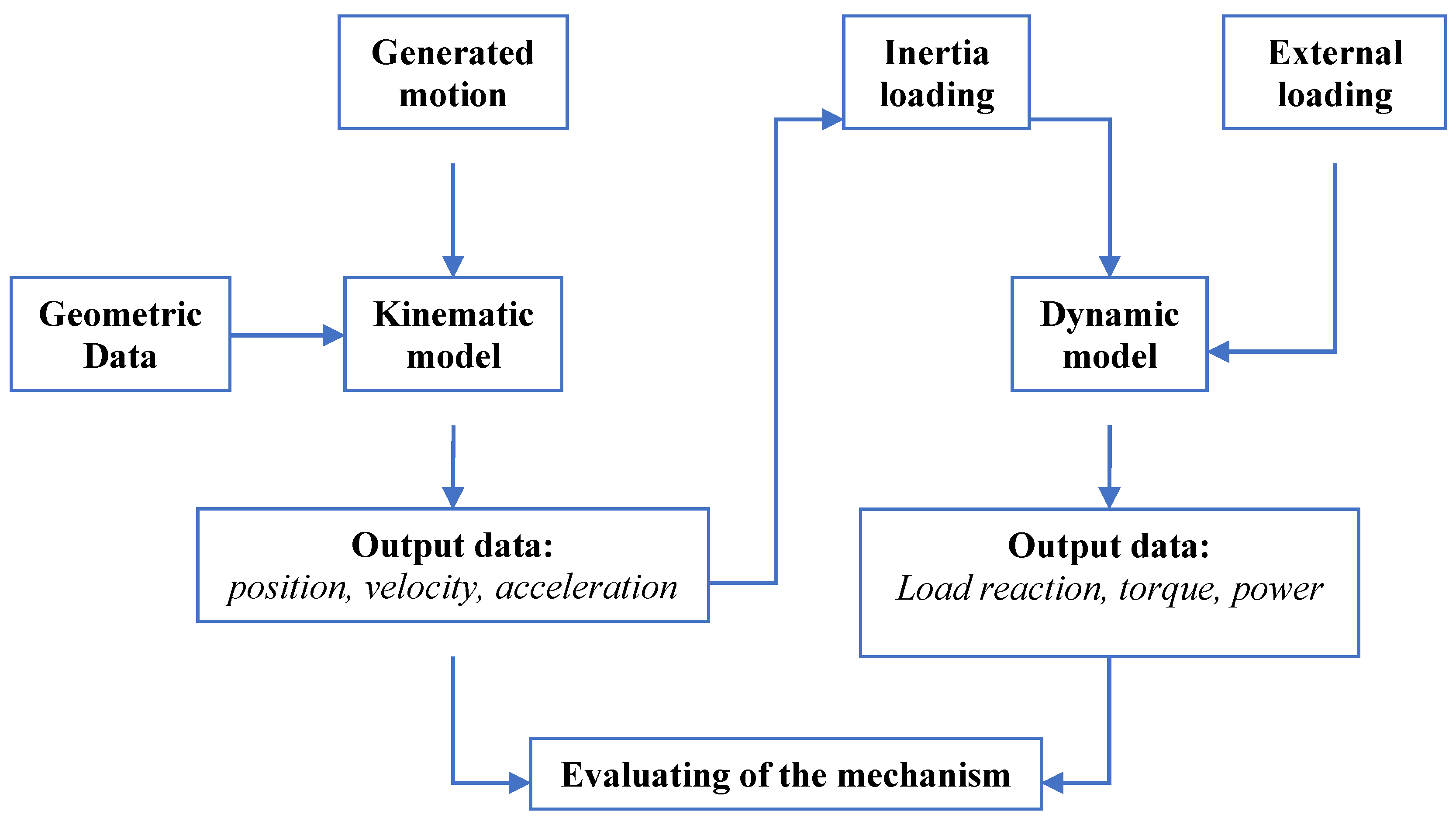
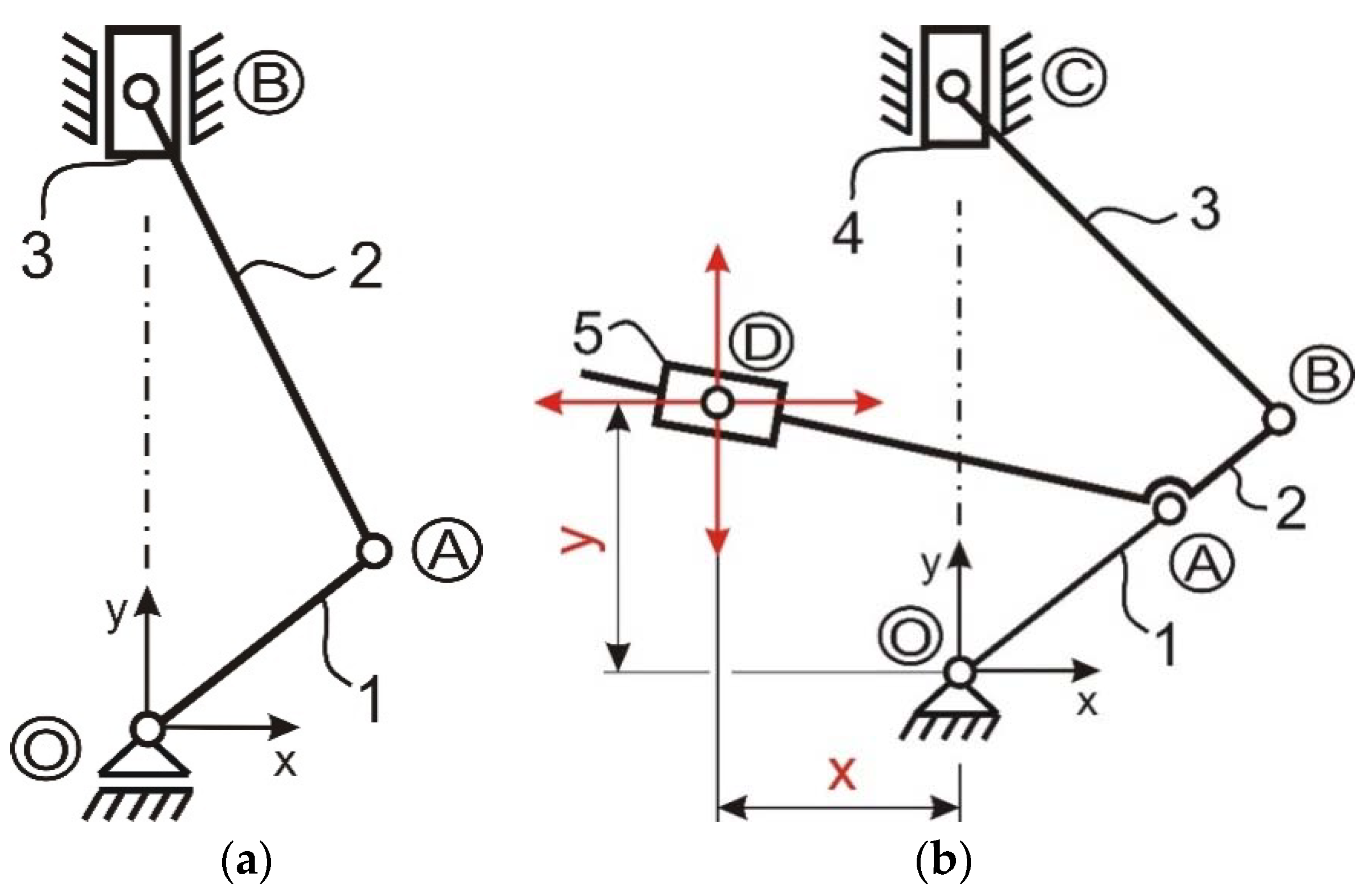
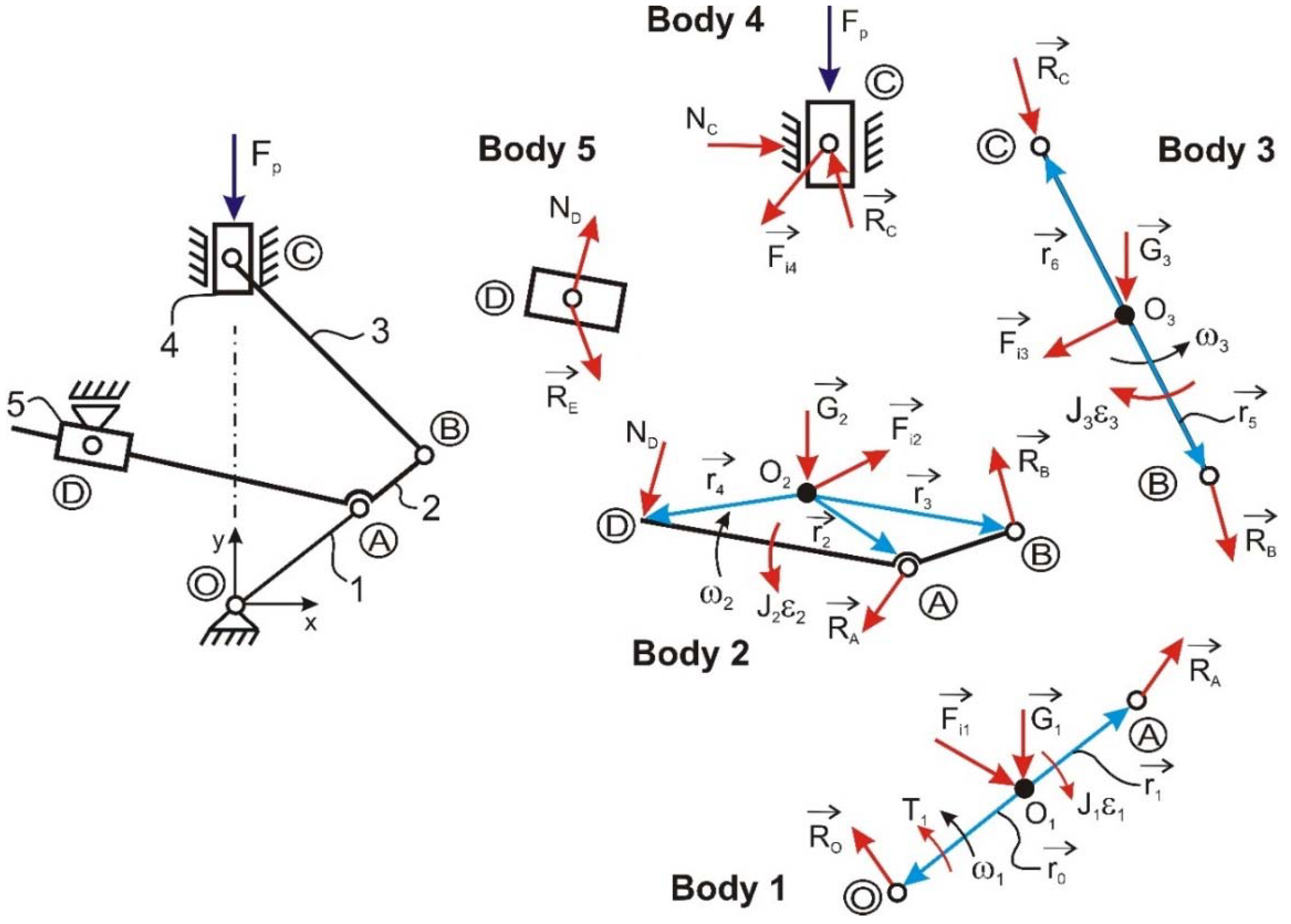
2. Simulation Method

The principle of functionality of a classical mechanism is known and, for this reason, it will not be detailed. This kind of mechanism converts rotating motion of crank into a translation motion of a piston. The overall principle is shown in Figure 2a.
In Figure 2b, we show the kinematic scheme for the case of a mechanism with an oscillating arm. The difference between these two types of mechanism concepts consists in how the con-rod is assembled in the mechanism: for a conventional engine, the con-rod is directly connected to the crankshaft, and for the engine with oscillating arm, the con-rod is connected to crankshaft through arm 2. This oscillating arm slides into an axial bearing (5) that is oscillated about D point, and it may also change the length of vector OB and the piston stroke. When the engine mechanism is running, the pivot point (D) can be moved in the vertical and horizontal direction and thus, the position of the oscillating arm is changed. In this way, we can obtain different values of the compression ratio and piston stroke. Finally, we can obtain an optimization of the engine working regimes depending also on the mechanical loading and crank speed.
In case of the engine mechanism with oscillating arm, the trajectory of the con-rod big end obtained on a complete crankshaft rotation is an ellipse, unlike the circular trajectory obtained on a conventional engine mechanism (Figure 3). This elliptical trajectory will determine an increase of piston motion time between top dead center and bottom dead center comparison by a conventional engine.
Maintaining the piston closer to the TDC (top dead center) as long as possible will create better conditions for ignition process at constant volume and an improvement of efficiency.
In order to demonstrate the advantages that the oscillating arm mechanism can bring, some scenario analysis has been made. As a particular case, we started the survey from a classical engine with the following characteristics: bore: 82 mm, stroke: 76 mm, crank speed range: 1000–6000 rpm. For a relevant comparative analysis, the same components were used for the two solutions analyzed. Basically, the element that makes the difference between the two solutions is the oscillating arm, together with the bearing in which it slides. The input data used for kinematic simulation is shown in the Table 1.
As can be viewed in the Figure 4, the pivot point was modified on the vertical direction to indicate how the stroke parameter is influenced and also chamber volume and compression ratio.
In Figure 4 and Figure 5, the nominal position of the bearing joints that connected the bearing to the engine block was noted with the letter D as was used on the kinematic scheme. As can be viewed in Figure 2b, the mechanism is related to the global coordinate system placed in the axis of the crankshaft. With respect to this GCS (Global coordinate system), the notations that define a new position of the bearing joint D were used as follows:
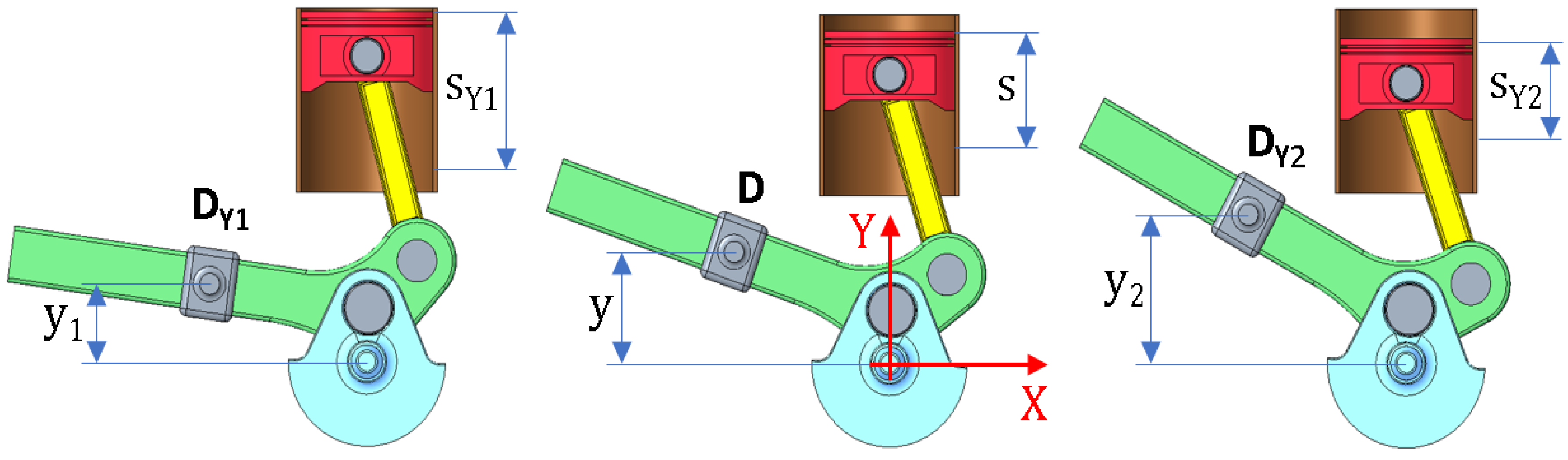
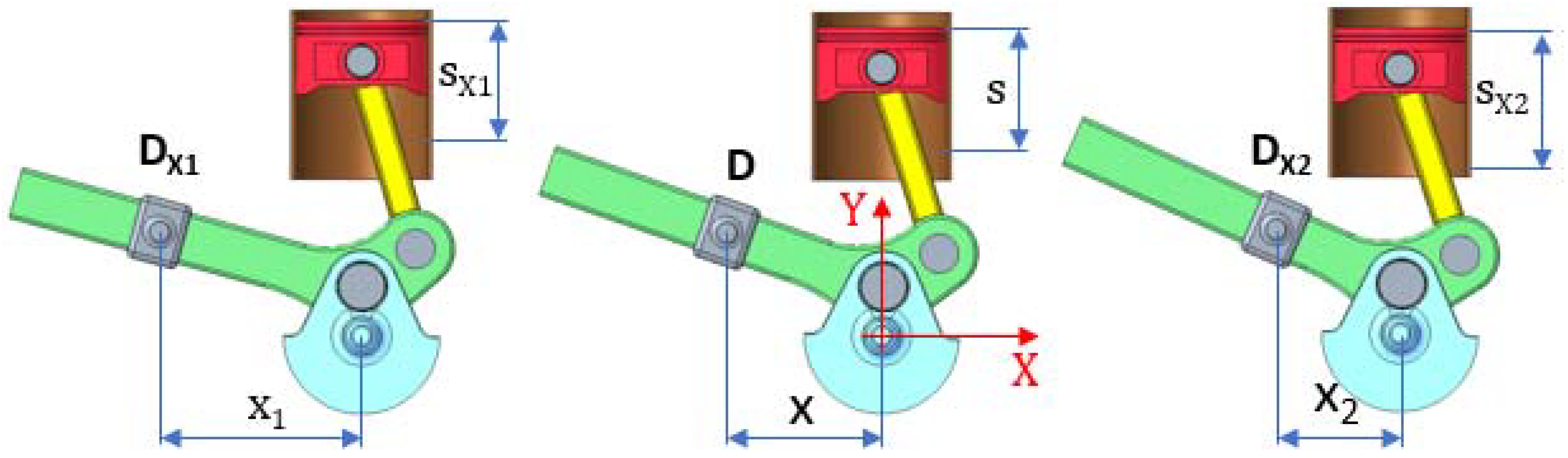
  • Ff the bearing joint is moved in the opposite direction with respect to GCS axes, the number “1” is used as a secondary subscript of the letter D; the first subscript indicates the axis direction of the movement takes place;
  • In a similar manner, a subscript number “2” will be used if the bearing joint is moved in the positive direction of the GCS axes. In the kinematic analysis, the movable range of pivot point has been considered as +/−40 mm on the horizontal direction and +/−25 mm on the vertical direction.
Table 2 contains an overview of results for all extreme positions of the pivot point (D) indicated in Figure 4 and for the initial position of this point. According to these results, it can be seen that moving point D on the right extreme position will lead to an increasing of stroke and a decrease of compression ratio relative to the initial position. Furthermore, the lowering of point D from initial position to the extreme down position will lead to an increase of stroke and compression ratio.
According to Figure 4, moving the pivot point in the upward direction will reduce the piston stroke and will increase the chamber volume when the piston is close to the TDC. Furthermore, moving the pivot point in a horizontal direction, the piston stroke is also reduced (Figure 5).
The stroke evolution on a complete crank angle rotation for different positions of the pivot point can be viewed on the both graphs from Figure 6.
In Figure 6a, we see the increase of the piston stroke moving the pivot point to the right side. Furthermore, the increase of the piston stroke can be obtained based on moving the pivot point in the upward direction (Figure 6b). It can be seen that the moving point to the vertical direction has a greater influence compared to that against moving in the horizontal direction.
To have better comparative information regarding the two solutions, a graph with the stroke obtained for the classic solution was overlaid on Figure 6. It can be viewed that the stroke for the VCR solution (with point D in a nominal position) is increased by 25%.
An improvement from the kinematic viewpoint will have an influence on the ratio compression and chamber volume and could also lead to improving the burning process on a complete cycle and consumption.
Other kinematic parameters analyzed as a comparison can be viewed in Figure 7. This is about velocity and acceleration of the piston.
Regarding the mechanism configurations analyzed, it can be viewed from the graphs that higher values are obtained using the VCR solution in comparison to the classic solution. More exactly, using the VCR solution, absolute maximum values obtained for velocity and acceleration piston are higher by 25% with respect to the conventional solution, considering a crankshaft speed rotation with a constant value of 6000 rpm.
In these conditions, from a dynamical viewpoint, the inertia loading that is proportional with acceleration could induce a slightly increasing effect that will influence the loading evolution in all joints of the mechanism. For this reason, some dynamic analyses were made to have a know-how about some important parameters such as load reactions, torque or power.
As it is known, to have a durability for a mechanism, it is desirable to have the internal forces that are as small as possible in the system. Furthermore, to have the best mechanical performance, it is desirable to obtain from these internal forces values of torque and power that are as large as possible, too. Basically, it has to be somewhere between ideal durability and ideal mechanical performance. For this reason, the loads from the joints and bearings must be studied based on dynamic simulations or analytical calculus.
It is well known that for a classic mechanism, in order to obtain the mechanical torque and internal loading from all joints, it will be necessary to write the equilibrium equations on all bodies from assembly based on the kineto–static methodology used in the Multi Body Dynamic calculus.
General equations that can be written for any individual body from an assembly are as follows:
  • for translational motion: F = m · a ;
  • for rotational motion: M = j · ε .
In the free body diagrams, the following notations have been used: r- arm length, R—magnitude force, G—weight element, Fi—inertia forces, J—inertia mass moment, Fp—piston force, N—normal force coming from a contact, ω—angular speed, ε—angular acceleration, T—engine torque).
As per example for the classic mechanism from Figure 8, the equations can be written as follow:
Body   1 :   { R ¯ o + R ¯ A + G ¯ 1 = F ¯ i 1 ( r ¯ o x   R ¯ o ) k ¯ + ( r ¯ 1 x   R ¯ A ) k ¯ + T ¯ 1 k ¯ = J 1 ε 1 Body   2 :   { R ¯ A + R ¯ B + G ¯ 2 = F ¯ i 2 ( r ¯ 2 x   R ¯ A ) k ¯ + ( r ¯ 3 x   R ¯ B ) k ¯ = J 2 ε 2 Body   3 : R ¯ B + N ¯ B + F ¯ p + G ¯ 2 = F ¯ i 3
where by “x” we have noted the cross product and with k ¯ the unit vector of the Oz axis.
As can be viewed from the system of Equation (1), the torque T1 can be obtained. Based on it, and knowing the speed of crank, it is possible to evaluate the power of an engine.
The torque T1 obtained from the system of Equation (1) is called the total torque of engine and is in fact a cumulative effect that comes from two sources: pressure inside cylinders and inertia.
If it is desired to find out the motor torque given only by the inertia effect, in the equations of system (1) the term Fp is considered equal to zero. Furthermore, if we want to find out the contribution of the pressure in a cylinder on the total torque T1, all terms from right side of equations from system (1) will be equal to zero.
Furthermore, in a similar manner, for the mechanism engine with oscillating arm (VCR solution) we will write the equations on all bodies from system and the torque will be determined.
For the mechanism with an oscillating arm from Figure 9, the equilibrium equations written on each body are shown in the system of Equation (2).
Body   1 :   { R ¯ o + R ¯ A + G ¯ 1 = F ¯ i 1 ( r ¯ o x   R ¯ o ) k ¯ + ( r ¯ 1 x   R ¯ A ) k ¯ + T ¯ 1 k ¯ = J 1 ε 1 Body   2 :   { R ¯ A + R ¯ B + G ¯ 2 + N ¯ D = F ¯ i 2 ( r ¯ 2 x   R ¯ A ) k ¯ + ( r ¯ 3 x   R ¯ B ) k ¯ + ( r ¯ 4 x   N ¯ D ) k ¯ = J 2 ε 2 Body   3 :   { R ¯ B + R ¯ C + G ¯ 3 = F ¯ i 3 ( r ¯ 5 x   R ¯ B ) k ¯ + ( r ¯ 6 x   R ¯ C ) k ¯ = J 3 ε 3 Body   4 : R ¯ C + N ¯ C + F ¯ p + G ¯ 4 = F ¯ i 4 Body   5 : N ¯ D + R ¯ E = 0
The input used to solve the system of Equations (1) and (2) was: the geometrical system with joint position, crankshaft speed and pressure from cylinders, as can be viewed in Figure 10 for three important crank speeds: idle speed, nominal speed and a speed close to the maximum torque. Figure 10a shows the in-cylinder pressure evolution in terms of crank speed. Furthermore, in Figure 10b, we show the evolution of in-cylinder pressure on a complete cycle only for the three crank speeds mentioned. The in-cylinder pressure was converted into the force pressure taking into account the area of the piston head (force gas pressure is obtained from multiplying pressure with the area of piston head). Details of input data are presented in Table 3.
Taking into account the system of Equations (1) and (2), and using multibody dynamic analyses, the total torque and inertia torque variation on a cylinder have been obtained for a complete cycle (two rotation of a crankshaft) with respect to three different crank speeds: idle, maximum torque, nominal. The graph evolutions of these can be viewed in Figure 11 and Figure 12. According to the graphs from Figure 11 and Figure 12, it can be seen that the maximum total torque value obtained for the VCR solution is higher against a classical engine mechanism. Furthermore, the power calculated for the input speed used will have a similar increasing percent.
From dynamic viewpoint analyses, to have an image about joint loading magnitude that influences the pin wear in time, Figure 11a show the evolution of the joint reaction for a complete cycle on the crank and con-rod pin when a crankshaft has nominal speed (6000 rpm). As can be viewed, in comparison with classic mechanism, the con-rod big end on the analyzed VCR solution has comparable values with the ones from the classic mechanism.
Furthermore, in the Figure 11a–d, we see the contribution of the inertia torque on the total torque engine. As can be viewed, contribution of the inertia torque from total engine torque is significantly at higher speeds. For lower speeds, the contribution of inertia is: at idle speed—8%, maximum torque speed—50%.
Based on the performed multibody dynamic analyses, Figure 12 shows the characteristic of power and torque for the two solutions studied. Both maximum power values and maximum torque values obtained have a percentage increasing close to 40% for the VCR solution.
Another important parameter to appreciate the performance of an engine is the lithic power that means the power divided at engine displacement. To evaluate this parameter for both configurations, it was taken into account that the engine displacement obtained for both solutions has different values caused by different strokes. For the classic solution, the stroke is lower by 25% compared to VCR and the engine displacement, too. Based on it, the lithic power obtained from the calculus for VCR is higher by 20% compared to the classic solution.

3. Conclusions

This review paper aimed to provide a comprehensive overview and a summary of results obtained for a novel solution of a mechanism used for an engine with variable compression ratio compared to a classical mechanism. The overall results were obtained from Multi-Body Simulation technique (MBS) and based on them; it was intended to evaluate kinematic and dynamic parameters from both mechanisms using the considered scenarios. The analytical approaches that are commonly used in the multi-body systems, such as equilibrium equations written only on one body from overall assembly, are reviewed thoroughly. In particular, the paper elaborated on the efficient modifications that can be applied or adopted to a classical engine mechanism. These modifications were applied through synthesizing a novel mechanism using a new configuration of the bodies in assembly thru implementation an oscillation arm between crankshaft and con-rod. Furthermore, possibility to change some kinematic and dynamic parameters from mechanisms through change in the position of the pivot point of oscillation arm was another important novelty.
The most important conclusions reached from the literature review are:
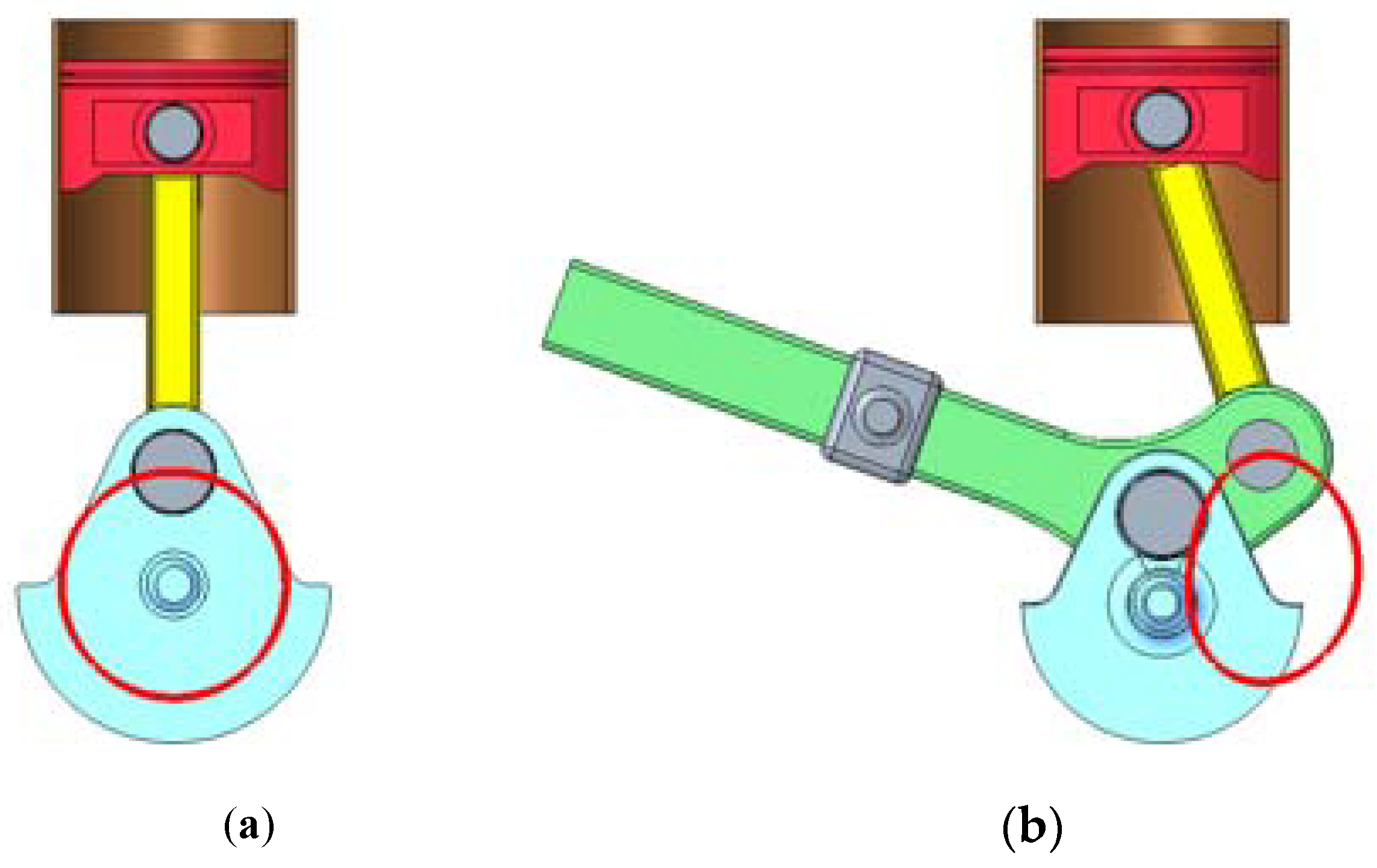
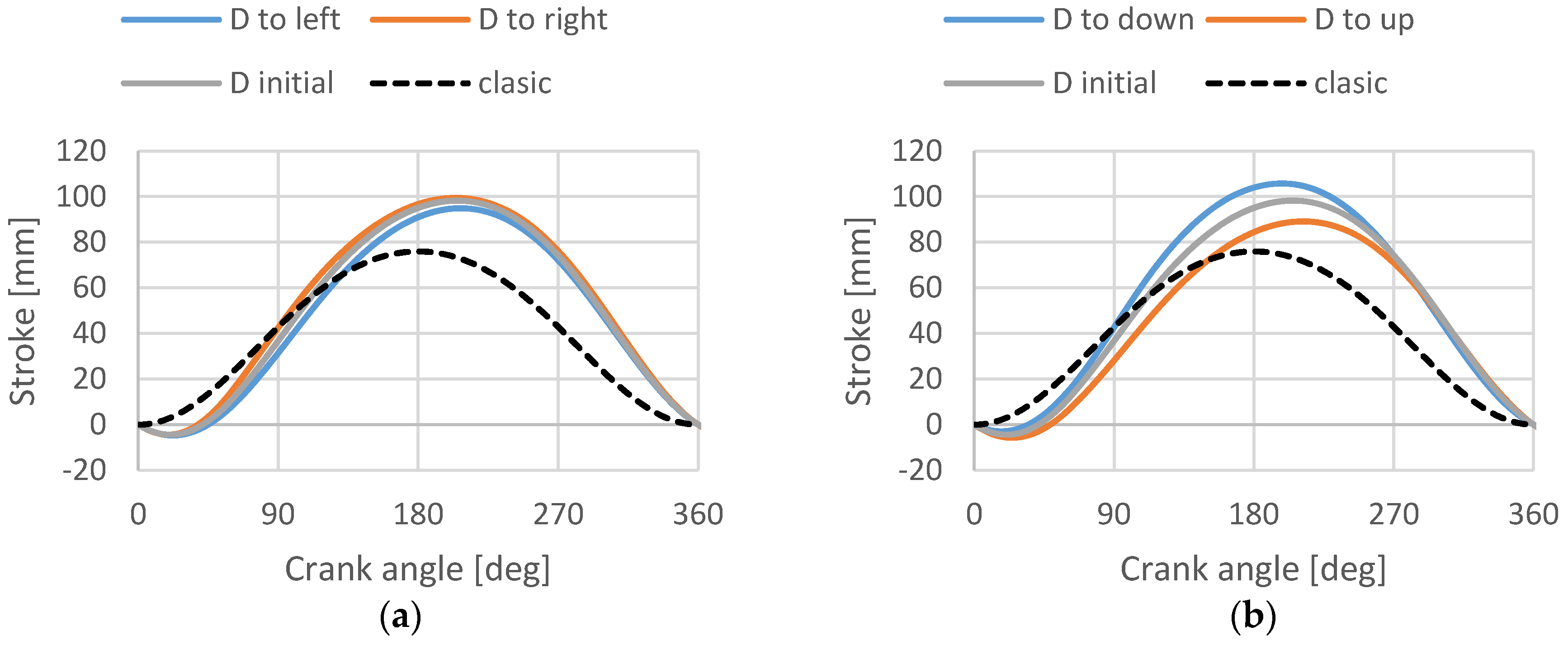
From a kinematic point of view, an increase of 25% was obtained for piston stroke on the novelty design mechanism compared to the classical one. This increase is due to the oscillating arm included in the configuration of the mechanism between the crankshaft and con-rod.
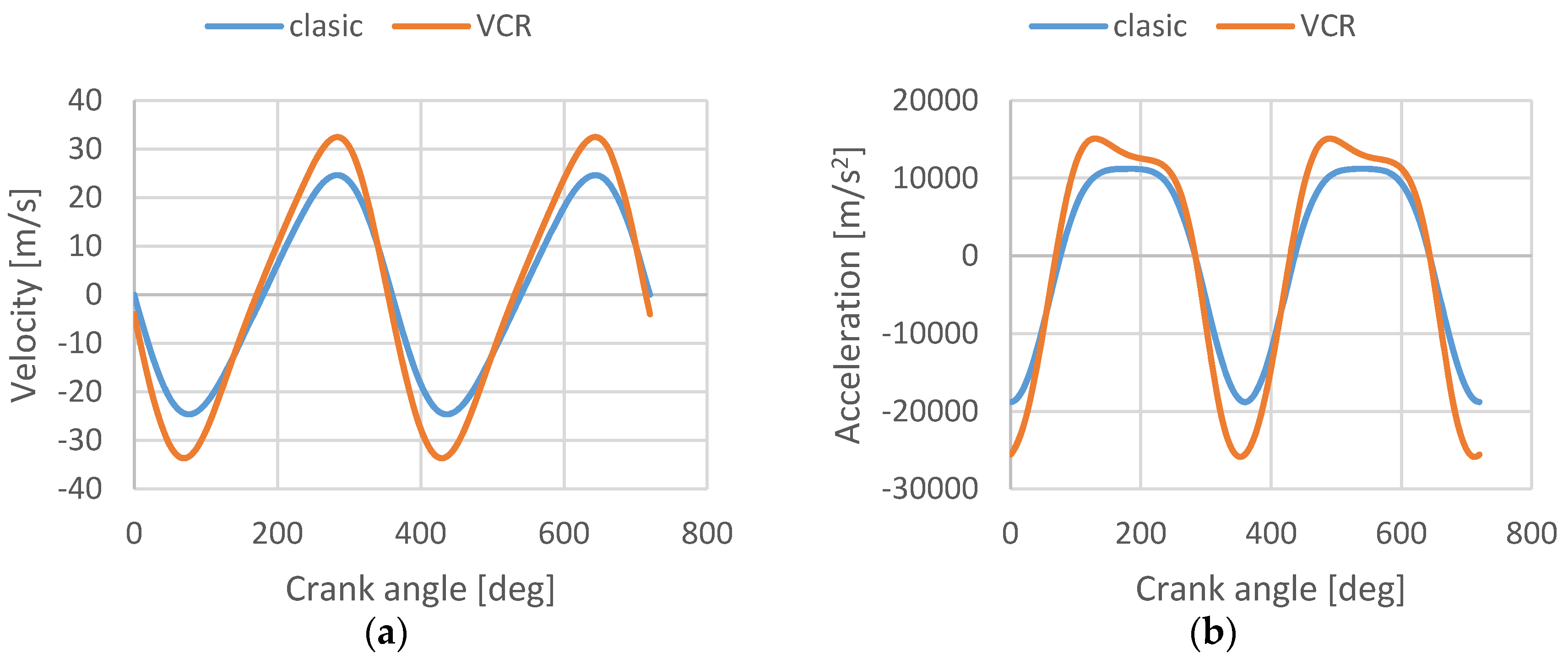
Furthermore, the velocity and acceleration of the piston for the novelty mechanism have a similar percent of increase with respect to the piston stroke obtained with a classic mechanism.
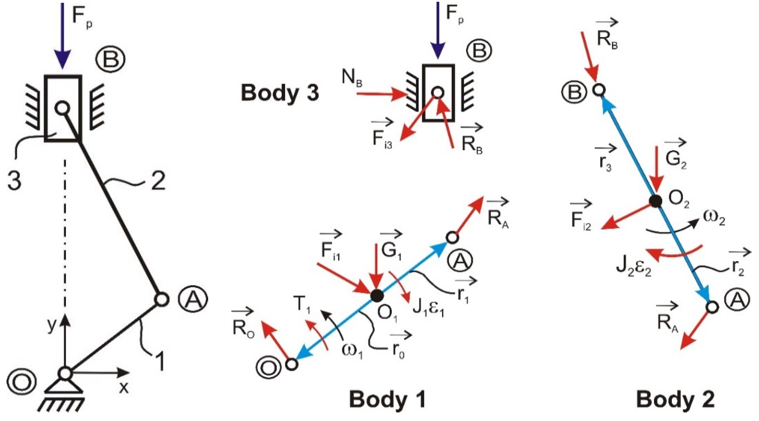
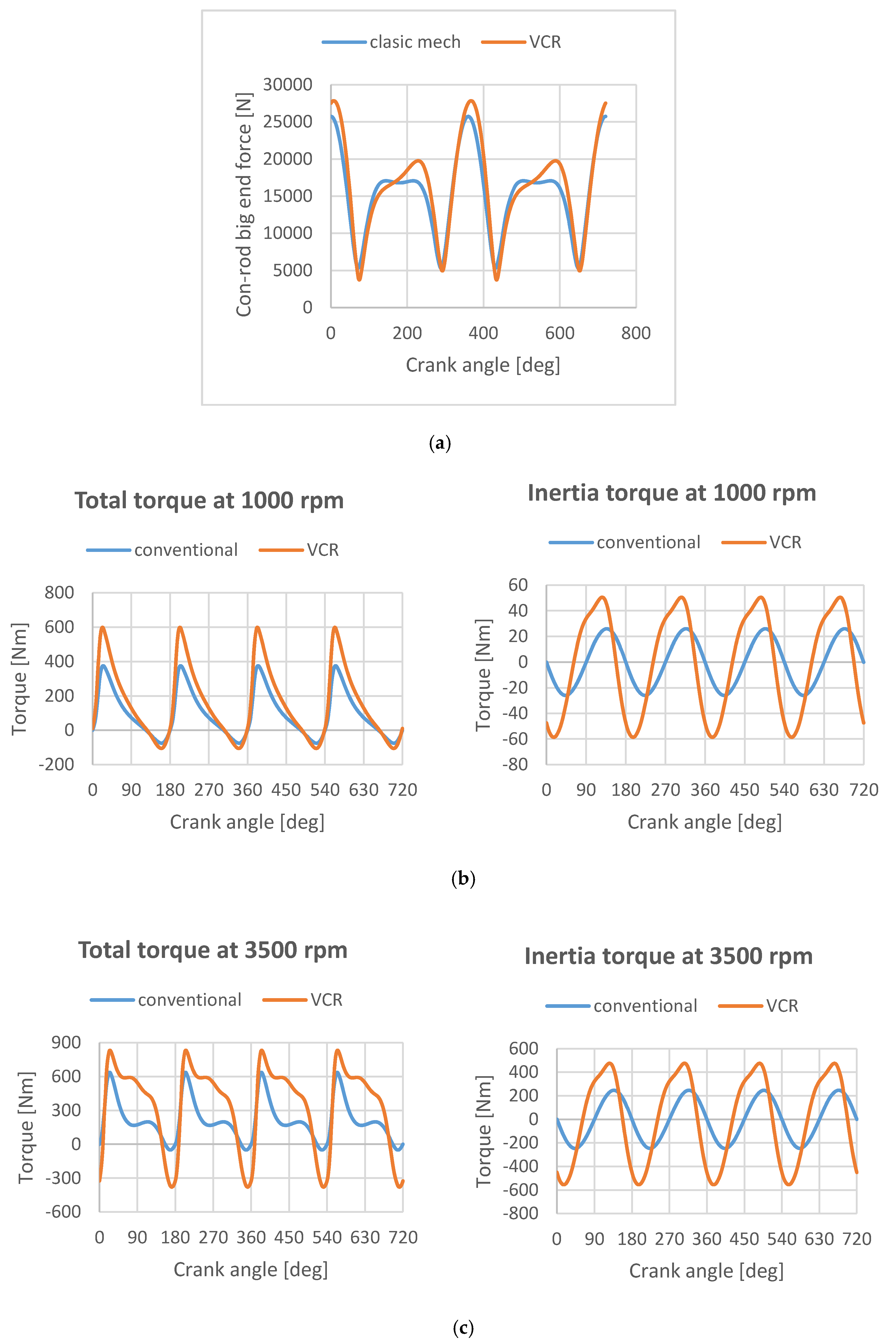
The percentage increase of the kinematic parameters also led to the increase of the internal dynamic loads in the mechanism. For example, in the novel mechanism, on the big end of a con-rod, a maximum value of the resulting dynamic load greater than 8% compared to the classical mechanism was obtained.
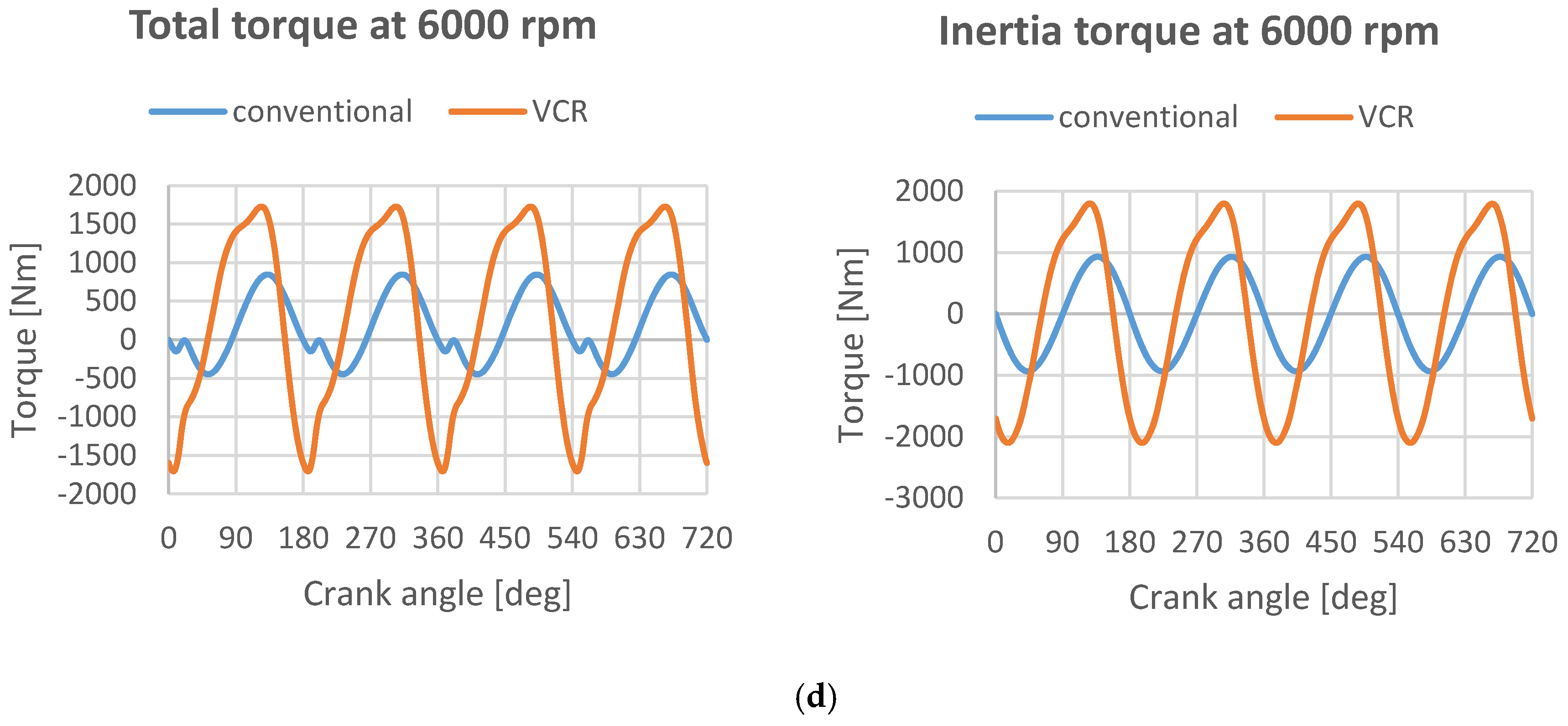
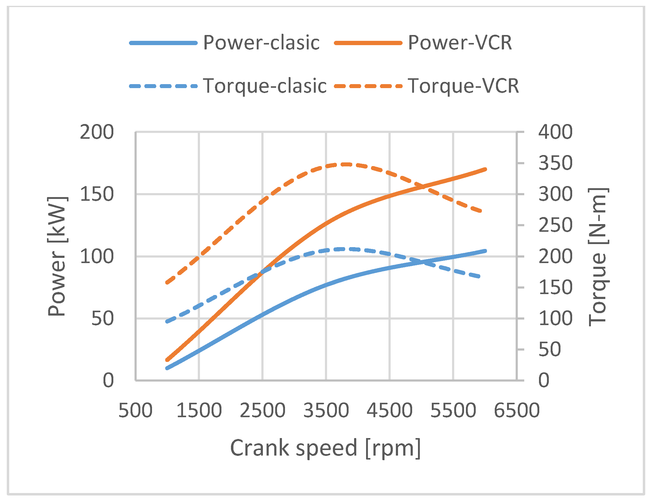
The dynamic loading reduced to the lever of crankshaft will induce an increase of the torque and also an increase of power. According to the simulations, a major percent of 40% is obtained for the novel mechanism compared to the classic one.
Finally, the lithic power calculated in terms of kinematic and dynamic parameters has a 20% increasing obtain for the novel mechanism comparison to the classic one.
Beside the advantageous highlights based on kinematic and dynamic analysis, it can be concluded that from constructive and functional viewpoints, considering the parameters determined from virtual simulation, the engine design with an oscillating arm provides a great advantage in comparison with conventional engine, considering that most parameters obtained from the analyses are accomplished.
The mechanism design solution with an oscillating arm can be adopted for most internal combustion engines with two or four-cycle engines, and for any type of engine dimensions.
Variable Compression Ratio (VCR) technology offers the largest potential improvement in part-throttle fuel efficiency and CO2 emissions when compared to other competing technologies. Furthermore, VCR technology can offer torque enhancement at low rpm when any boost or auxiliary systems are least effective.
A possible obstacle to adoption a VCR solution could be the incompatibility with major components from current production and difficulties of combining VCR and non-VCR manufacturing within existing plants. As environmental pressure on the automobile increases and investment plans for new products are put in place, the justification for VCR will become more evident.
Taking into account that large numbers of combustion engines are made every year, the VCR engine with an oscillating arm can represent a very good solution for novel engine design.

Author Contributions

Data curation, C.I.; Formal analysis, M.-L.S.; Project administration, C.I.P.; Writing—original draft, R.M. All authors have read and agreed to the published version of the manuscript.

Funding

This research received no external funding.

Acknowledgments

This work was supported in part by the Department of Mechanical Engineering, Transilvania University of Braşov, Romania.

Conflicts of Interest

The authors declare no conflict of interest.

References

  1. Kushwaha, M.; Gupta, S.; Kelly, P.; Rahnejat, H. Elasto-multi-body dynamics of a multicylinder internal combustion engine. Proc. Inst. Mech. Eng. Part K J. Multibody Dyn. 2002, 216, 281–293. [Google Scholar] [CrossRef] [Green Version]
  2. Louvigny, Y.; Duysinx, P. Advanced engine dynamics using MBS: Application to twin-cylinder boxer engines. In Proceedings of the 1st Joint International Conference on Multibody System Dynamics, Lappeenranta, Finland, 25–27 May 2010. [Google Scholar]
  3. Joshi, M.P.; Aparna, V.K. Variable Compression Ratio (VCR) Engine—A review of future power plant for automobile. IJMERD 2012, 2, 1159–1168. [Google Scholar]
  4. Nakamura, H. A Low Vibration Engine with Unique Counter-Balance Shafts. SAE Trans. 1976, 85, 397–412. [Google Scholar]
  5. Thomson, W. Fundamentals of Automotive Balance; Mechanical Engineering Publications Ltd.: London, UK, 1978; 96p. [Google Scholar]
  6. Schedel, R. A Breakthrough in Technology? Auto Technol. 2001, 1, 26–27. [Google Scholar]
  7. Webb, A. A Piston Revolution. Eng. Manag. J. 2002, 17, 25–30. [Google Scholar]
  8. Wharton, A.J. Diesel Engines, 3rd ed.; Elsevier: Butterworth-Heinemann, UK, 2013; 144p. [Google Scholar]
  9. Kojima, S.; Kiga, S.; Moteki, K.; Takahashi, E.; Matsuoka, K. Development of a New 2L Gasoline VC-Turbo Engine with the World’s First Variable Compression Ratio Technology. SAE Tech. Pap. 2018. [Google Scholar] [CrossRef]
  10. Shaik, A.; Moorthi, N.S.V.; Rudramoorthy, R. Variable compression ratio engine: A future power plant for automobiles—An overview. Proc. Inst. Mech. Eng. Part D J. Automob. Eng. 2007, 221, 1159–1168. [Google Scholar] [CrossRef]
  11. Pesic, R.; Milojevic, S. Efficiency and ecological characteristics of a VCR diesel engine. Int. J. Automot. Technol. 2013, 14, 675–681. [Google Scholar] [CrossRef]
  12. Milojević, S.; Pešić, R. Determination of Combustion Process Model Parameters in Diesel Engine with Variable Compression Ratio. J. Combust. 2018, 8, 212–218. [Google Scholar] [CrossRef]
  13. Hosamani, B.R.; Kattib, V.V. Experimental analysis of combustion characteristics of CI DI VCR engine using mixture of two biodiesel blend with diesel. Eng. Sci. Technol. Int. J. 2018, 21, 769–777. [Google Scholar] [CrossRef]
  14. Mishra, R.K.; Soota, T.; Singh, R. Effect of Variable Compression Ratio on Performance of a Diesel Engine Fueled with Karanja Biodiesel and its Blends. IOP Conf. Ser. Mater. Sci. Eng. 2017, 225, 012064. [Google Scholar] [CrossRef] [Green Version]
  15. Nayyar, A.; Sharma, D.; Soni, S.L.; Mathur, A. Experimental investigation of performance and emissions of a VCR diesel engine fuelled with n-butanol diesel blends under varying engine parameters. Environ. Sci. Pollut. Res. Int. 2017, 24, 20315–20329. [Google Scholar] [CrossRef] [PubMed]
  16. Vairavel, M.; Chandrasekaran, M.; Vivek, P.; Kumar, V. Empirical performance analysis of VCR engine fuelled with karanja oil and various additives using ANOVA technique. Int. J. Ambient Energy 2020, 41, 369–373. [Google Scholar] [CrossRef]
  17. Drangel, H.; Reinmann, R.; Olofsson, E. The Variable Compression (Svc) and the Combustion Control (Scc)—Two Ways to Improve Fuel Economy and Still Comply with World-Wide Emission Requirements; SAE Technical Paper 2002-01-0996; SAE Int.: Warrendale, PA, USA, 2002. [Google Scholar] [CrossRef]
  18. Duchemin, M.; Collee, V. Profile optimization of the teeth of the double rack-and-pinion gear mechanism in the MCE-5 VCRi engine. SAE Int. J. Engines 2016, 9, 1786–1794. [Google Scholar] [CrossRef] [Green Version]
  19. Vlase, S.; Teodorescu, P.P.; Itu, C.; Scutaru, M.L. Elasto-Dynamics of a Solid with a General “Rigid” Motion using FEM Model. Theoretical Approach. Rom. J. Phys. 2013, 58, 882–892. [Google Scholar]
  20. Vlase, S. Dynamical Response of a Multibody System with Flexible Elements with a General Three-Dimensional Motion. Rom. J. Phys. 2012, 57, 676–693. [Google Scholar]
  21. Vlase, S. Elimination of Lagrangian-Multipliers. Mech. Res. Commun. 1987, 14, 17–22. [Google Scholar] [CrossRef]
  22. Rahnejat, H.; Rothberg, S. Multi-Body Dynamics: Monitoring and Simulation Techniques—III; Professional Engineering Publications: London, UK, 2004; 544p. [Google Scholar]
  23. Yogesh, M. VCR Technology in Si Engine with LPG: Emission Norms; Lap Lambert Academic Publishing: Saarbrücken, Germany, 2012. [Google Scholar]
  24. DeGooijer, L.H. A Reciprocating Piston Mechanism and a Method of Increasing Internal egr in an Internal Combustion Engine. U.S. Patent No. WO2009100759A1, 20 August 2009. [Google Scholar]
  25. DeGooijer, L.H. A Reciprocating Piston Mechanism. U.S. Patent No. WO2011006537A1, 20 January 2011. [Google Scholar]
  26. Pischinger, S.; Wittek, K.; Tiemann, C. Two-stage Variable Compression Ratio with Eccentric Piston Pin MTZ worldwide. Springer Automot. Media 2009, 70, 20–27. [Google Scholar]
  27. Kleeberg, H.; Tomazic, D.; Dohmen, J.; Wittek, K.; Balazs, A. Increasing Efficiency in Gasoline Powertrains with a Two-Stage Variable Compression Ratio (VCR) System. SAE 2013 World Congress & Exhibition, RWTH Aachen University; SAE Technical Paper, Article 2013-01-0288; SAE Int.: Warrendale, PA, USA; Aachen, Germany, 2013. [Google Scholar]
  28. Tomazic, D.; Kleeberg, H.; Bowyer, S.; Dohmen, J.; Wittek, K.; Haake, B. Two-Stage Variable Compression Ratio (VCR) System to Increase Efficiency in Gasoline Powertrains. In Proceedings of the DEER Conference, Dearborn, MI, USA, 16 October 2012; pp. 267–276. [Google Scholar]
  29. Rao, V.D.N.; German, D.J.; Vrsek, G.A.; Chottiner, J.E.; Madin, M.M. Variable Compression Ratio Pistons and Connecting Rods. U.S. Patent 6,568,357 B1, 18 October 2000. [Google Scholar]
  30. Schiehlen, W. Research trends in multibody system dynamics. Multibody Syst. Dyn. 2007, 18, 3–13. [Google Scholar] [CrossRef]
  31. Setright, L.J.K. Some Unusual Engines. In The Institute of Mechanic Engineering; Mechanical Engineering Publications Ltd.: London, UK, 1975. [Google Scholar]
  32. Twigg, P. Science for Motor Vehicle Engineers, 1st ed.; Elsevier: Butterworth-Heinemann, UK, 2012; 304p. [Google Scholar]
  33. SIMDRIVE 3D Documentation. Available online: http://www.contecs-engineering.de (accessed on 15 March 2020).
  34. Taylor, C.F. The Internal Combustion Engine. In Theory and Practice; MIT Press: Cambrige, MA, USA, 1966; Volume 1, 584p. [Google Scholar]
  35. Vlase, S.; Danasel, C.; Scutaru, M.L.; Mihalcica, M. Finite Element Analysis of a Two-Dimensional Linear Elastic Systems with a Plane “Rigid Motion”. Rom. J. Phys. 2014, 59, 476–487. [Google Scholar]
  36. Styron, J. Variable Compression Ratio Internal Combustion Engine Using Field-Sensitive Fluid. U.S. Patent No. 6394048 B1, 16 January 2001. [Google Scholar]
  37. RazaKhan, I.R.; Kailas, T.M. Study of Variable Compression Ratio Engine (VCR) and Different Innovations to Achieve VCR. Int. J. Res. Appl. Sci. Eng. Technol. 2017, 7, 344–349. [Google Scholar]
  38. Witteka, K. Experimental Investigation of a Variable Compression Ratio System Applied to a Gasoline Passenger Car Engine, Energy Conversion and Management; Elsevier Ltd.: Amsterdam, The Netherlands, 2019; Volume 183, pp. 753–763. [Google Scholar]
  39. Tomar, S.K.; Mishra, R.K.; Bisht, S.; Kumar, S.; Saxena, G. Design of Variable Length Connecting rod for VCR Engine. Int. J. Eng. Res. Appl. 2014, 6, 280–285. [Google Scholar]
  40. Joshi, M.P. Variable compression ratio (vcr) engine—A review of future power plant for automobile. Int. J. Mech. Eng. Res. Dev. IJMERD 2012, 2, 2–3. [Google Scholar]
  41. Kitayama, S.; Saikyo, M.; Nishio, Y.; Tsutsumi, K. Torque control strategy and optimization for fuel consumption and emission reduction in parallel hybrid electric vehicles. Struct. Multidisc. Optim. 2015, 52, 595. [Google Scholar] [CrossRef]
  42. Available online: http://www.altair.com (accessed on 15 March 2020).
  43. Available online: http://www.simulia.com (accessed on 15 March 2020).
  44. Available online: http://www.mscsoftware.com (accessed on 15 March 2020).
  45. Available online: http://www.ansys.com (accessed on 15 March 2020).
  46. Gomecsys Homepage. Available online: https://gomecsys.com/our-product/gomecsys-vcr-technology (accessed on 15 March 2020).
  47. Aoyama, S. Study of a Variable Compression Ratio System, Nissan. AutoTechnology 2007, 2, 65–68. [Google Scholar]
  48. Ryosuke, H. Variable Compression Ratio Internalcombustion Engine. U.S. Patent 8,881,695 B2, 3 April 2013. [Google Scholar]
  49. Chiodi, M.; Kaechele, A.; Bargende, M.; Wichelhaus, D.; Poetsch, C. Development of an innovative combustion process: Spark-assisted compression ignition. SAE Int. J. Engines 2017, 10, 5. [Google Scholar] [CrossRef]
  50. Nakata, K.; Nogawa, S.; Takahashi, D.; Kumagai, A.; Suzuki, T. Engine technologies for achieving 45% thermal efficiency of S.I. engine. SAE Int. J. Engines 2016, 9, 1. [Google Scholar] [CrossRef]
Figure 1. General Bloc diagram to evaluate a mechanism based on a multibody simulation.
Applsci 10 02733 g001
Figure 2. Kinematic schema for two concept of engine mechanism: (a) classic; (b) with oscillating arm.
Applsci 10 02733 g002
Figure 3. Trajectory of the con rod big end for a complete rotation of crank shaft: (a) classic; (b) VCR.
Applsci 10 02733 g003
Figure 4. Piston stroke influence with modifying the pivot point on vertical direction.
Applsci 10 02733 g004
Figure 5. Piston stroke influence with modifying the pivot point on horizontal direction.
Applsci 10 02733 g005
Figure 6. Piston stroke evolution during complete rotation of crankshaft when the pivot point is moved in: (a) horizontal direction (b) vertical direction.
Applsci 10 02733 g006
Figure 7. Kinematic parameters evolution on a complete cycle rotation crankshaft: (a) piston velocity; (b) piston acceleration.
Applsci 10 02733 g007
Figure 8. Free body diagram for the classical mechanism.
Applsci 10 02733 g008
Figure 9. Free body diagram for the mechanism with oscillating arm—VCR.
Applsci 10 02733 g009
Figure 10. Pressure evolution on a cylinder used as input data in analyses (a) depending on crank speed; (b) depending on crank angle for a complete cycle (c) sketch of the engine [13].
Applsci 10 02733 g010
Figure 11. (a). Con-rod big end force [N], (b). Torque engine evolution on a complete cycle for a total torque of 1000 rpm, (c). Torque engine evolution on a complete cycle for a total torque of 3500 rpm, (d). Torque engine evolution on a complete cycle for a total torque of 6000 rpm.
Applsci 10 02733 g011aApplsci 10 02733 g011b
Figure 12. Engine performance: classic versus VCR.
Applsci 10 02733 g012
Table 1. Kinematic input data.
Initial Position of Joints Considering in Mechanism [mm]
JointClassicVCR
xyxy
O0000
A038038
B016543.1563.5
C 0207.2
D−12080
Table 2. Output kinematic parameters for extreme position of pivot point D.
D Point ExtremePositionClearance [mm]Stroke [mm]Bore Diameter [mm]Total Volume [L]Clearance Volume [L]Compression Ratio (CR)
initial13.7898.21820.59 0.078.13
Left9.8094.88 ↘820.550.0510.68 ↗
Right21.3599.42 ↗820.640.115.66 ↘
Down6.18105.7 ↗820.590.0318.1 ↗
Up21.2089.1 ↘820.580.115.2 ↘
↗: Increase; ↘: Decrese.
Table 3. Dynamic input data.
ElementClassicVCR
Mass [kg]Inertia Moment [kg∙mm2]Mass [kg]Inertia Moment [kg∙mm2]
1—crank16.524,56016.524,560
2—con-rod0.311850.31185
3—piston0.354387.50.354387.5
4—oscillation arm1.5513,400
5—pivot0.275100

